EP3755901B1 - Leistungswinkelvorwärtskopplungssignal für phasenregelschleife in windkraftanlagen - Google Patents
Leistungswinkelvorwärtskopplungssignal für phasenregelschleife in windkraftanlagen Download PDFInfo
- Publication number
- EP3755901B1 EP3755901B1 EP19757424.7A EP19757424A EP3755901B1 EP 3755901 B1 EP3755901 B1 EP 3755901B1 EP 19757424 A EP19757424 A EP 19757424A EP 3755901 B1 EP3755901 B1 EP 3755901B1
- Authority
- EP
- European Patent Office
- Prior art keywords
- power
- pll
- signal
- angle signal
- power system
- Prior art date
- Legal status (The legal status is an assumption and is not a legal conclusion. Google has not performed a legal analysis and makes no representation as to the accuracy of the status listed.)
- Active
Links
Images


Classifications
-
- H—ELECTRICITY
- H02—GENERATION; CONVERSION OR DISTRIBUTION OF ELECTRIC POWER
- H02J—ELECTRIC POWER NETWORKS; CIRCUIT ARRANGEMENTS OR SYSTEMS FOR SUPPLYING OR DISTRIBUTING ELECTRIC POWER; SYSTEMS FOR STORING ELECTRIC ENERGY
- H02J3/00—Circuit arrangements for AC mains or AC distribution networks
- H02J3/18—Arrangements for adjusting, eliminating or compensating reactive power in networks
-
- F—MECHANICAL ENGINEERING; LIGHTING; HEATING; WEAPONS; BLASTING
- F03—MACHINES OR ENGINES FOR LIQUIDS; WIND, SPRING, OR WEIGHT MOTORS; PRODUCING MECHANICAL POWER OR A REACTIVE PROPULSIVE THRUST, NOT OTHERWISE PROVIDED FOR
- F03D—WIND MOTORS
- F03D7/00—Controlling wind motors
- F03D7/02—Controlling wind motors the wind motors having rotation axis substantially parallel to the air flow entering the rotor
- F03D7/04—Automatic control; Regulation
- F03D7/042—Automatic control; Regulation by means of an electrical or electronic controller
- F03D7/048—Automatic control; Regulation by means of an electrical or electronic controller controlling wind farms
-
- F—MECHANICAL ENGINEERING; LIGHTING; HEATING; WEAPONS; BLASTING
- F03—MACHINES OR ENGINES FOR LIQUIDS; WIND, SPRING, OR WEIGHT MOTORS; PRODUCING MECHANICAL POWER OR A REACTIVE PROPULSIVE THRUST, NOT OTHERWISE PROVIDED FOR
- F03D—WIND MOTORS
- F03D9/00—Adaptations of wind motors for special use; Combinations of wind motors with apparatus driven thereby; Wind motors specially adapted for installation in particular locations
- F03D9/20—Wind motors characterised by the driven apparatus
- F03D9/25—Wind motors characterised by the driven apparatus the apparatus being an electrical generator
- F03D9/255—Wind motors characterised by the driven apparatus the apparatus being an electrical generator connected to electrical distribution networks; Arrangements therefor
- F03D9/257—Wind motors characterised by the driven apparatus the apparatus being an electrical generator connected to electrical distribution networks; Arrangements therefor the wind motor being part of a wind farm
-
- H—ELECTRICITY
- H02—GENERATION; CONVERSION OR DISTRIBUTION OF ELECTRIC POWER
- H02J—ELECTRIC POWER NETWORKS; CIRCUIT ARRANGEMENTS OR SYSTEMS FOR SUPPLYING OR DISTRIBUTING ELECTRIC POWER; SYSTEMS FOR STORING ELECTRIC ENERGY
- H02J13/00—Circuit arrangements for providing remote monitoring or remote control of equipment in a power distribution network
- H02J13/12—Monitoring network conditions, e.g. electrical magnitudes or operational status
-
- H—ELECTRICITY
- H02—GENERATION; CONVERSION OR DISTRIBUTION OF ELECTRIC POWER
- H02J—ELECTRIC POWER NETWORKS; CIRCUIT ARRANGEMENTS OR SYSTEMS FOR SUPPLYING OR DISTRIBUTING ELECTRIC POWER; SYSTEMS FOR STORING ELECTRIC ENERGY
- H02J3/00—Circuit arrangements for AC mains or AC distribution networks
- H02J3/38—Arrangements for feeding a single network from two or more generators or sources in parallel; Arrangements for feeding already energised networks from additional generators or sources in parallel
- H02J3/381—Dispersed generators
-
- H—ELECTRICITY
- H02—GENERATION; CONVERSION OR DISTRIBUTION OF ELECTRIC POWER
- H02K—DYNAMO-ELECTRIC MACHINES
- H02K7/00—Arrangements for handling mechanical energy structurally associated with dynamo-electric machines, e.g. structural association with mechanical driving motors or auxiliary dynamo-electric machines
- H02K7/18—Structural association of electric generators with mechanical driving motors, e.g. with turbines
- H02K7/1807—Rotary generators
- H02K7/1823—Rotary generators structurally associated with turbines or similar engines
- H02K7/183—Rotary generators structurally associated with turbines or similar engines wherein the turbine is a wind turbine
- H02K7/1838—Generators mounted in a nacelle or similar structure of a horizontal axis wind turbine
-
- H—ELECTRICITY
- H02—GENERATION; CONVERSION OR DISTRIBUTION OF ELECTRIC POWER
- H02P—CONTROL OR REGULATION OF ELECTRIC MOTORS, ELECTRIC GENERATORS OR DYNAMO-ELECTRIC CONVERTERS; CONTROLLING TRANSFORMERS, REACTORS OR CHOKE COILS
- H02P9/00—Arrangements for controlling electric generators for the purpose of obtaining a desired output
- H02P9/009—Circuit arrangements for detecting rotor position
-
- H—ELECTRICITY
- H02—GENERATION; CONVERSION OR DISTRIBUTION OF ELECTRIC POWER
- H02P—CONTROL OR REGULATION OF ELECTRIC MOTORS, ELECTRIC GENERATORS OR DYNAMO-ELECTRIC CONVERTERS; CONTROLLING TRANSFORMERS, REACTORS OR CHOKE COILS
- H02P9/00—Arrangements for controlling electric generators for the purpose of obtaining a desired output
- H02P9/02—Details of the control
-
- H—ELECTRICITY
- H03—ELECTRONIC CIRCUITRY
- H03L—AUTOMATIC CONTROL, STARTING, SYNCHRONISATION OR STABILISATION OF GENERATORS OF ELECTRONIC OSCILLATIONS OR PULSES
- H03L7/00—Automatic control of frequency or phase; Synchronisation
- H03L7/06—Automatic control of frequency or phase; Synchronisation using a reference signal applied to a frequency- or phase-locked loop
- H03L7/08—Details of the phase-locked loop
-
- F—MECHANICAL ENGINEERING; LIGHTING; HEATING; WEAPONS; BLASTING
- F03—MACHINES OR ENGINES FOR LIQUIDS; WIND, SPRING, OR WEIGHT MOTORS; PRODUCING MECHANICAL POWER OR A REACTIVE PROPULSIVE THRUST, NOT OTHERWISE PROVIDED FOR
- F03D—WIND MOTORS
- F03D7/00—Controlling wind motors
- F03D7/02—Controlling wind motors the wind motors having rotation axis substantially parallel to the air flow entering the rotor
- F03D7/0272—Controlling wind motors the wind motors having rotation axis substantially parallel to the air flow entering the rotor by measures acting on the electrical generator
-
- F—MECHANICAL ENGINEERING; LIGHTING; HEATING; WEAPONS; BLASTING
- F03—MACHINES OR ENGINES FOR LIQUIDS; WIND, SPRING, OR WEIGHT MOTORS; PRODUCING MECHANICAL POWER OR A REACTIVE PROPULSIVE THRUST, NOT OTHERWISE PROVIDED FOR
- F03D—WIND MOTORS
- F03D7/00—Controlling wind motors
- F03D7/02—Controlling wind motors the wind motors having rotation axis substantially parallel to the air flow entering the rotor
- F03D7/028—Controlling wind motors the wind motors having rotation axis substantially parallel to the air flow entering the rotor controlling wind motor output power
- F03D7/0284—Controlling wind motors the wind motors having rotation axis substantially parallel to the air flow entering the rotor controlling wind motor output power in relation to the state of the electric grid
-
- H—ELECTRICITY
- H02—GENERATION; CONVERSION OR DISTRIBUTION OF ELECTRIC POWER
- H02J—ELECTRIC POWER NETWORKS; CIRCUIT ARRANGEMENTS OR SYSTEMS FOR SUPPLYING OR DISTRIBUTING ELECTRIC POWER; SYSTEMS FOR STORING ELECTRIC ENERGY
- H02J2101/00—Supply or distribution of decentralised, dispersed or local electric power generation
- H02J2101/20—Dispersed power generation using renewable energy sources
- H02J2101/28—Wind energy
-
- Y—GENERAL TAGGING OF NEW TECHNOLOGICAL DEVELOPMENTS; GENERAL TAGGING OF CROSS-SECTIONAL TECHNOLOGIES SPANNING OVER SEVERAL SECTIONS OF THE IPC; TECHNICAL SUBJECTS COVERED BY FORMER USPC CROSS-REFERENCE ART COLLECTIONS [XRACs] AND DIGESTS
- Y02—TECHNOLOGIES OR APPLICATIONS FOR MITIGATION OR ADAPTATION AGAINST CLIMATE CHANGE
- Y02E—REDUCTION OF GREENHOUSE GAS [GHG] EMISSIONS, RELATED TO ENERGY GENERATION, TRANSMISSION OR DISTRIBUTION
- Y02E10/00—Energy generation through renewable energy sources
- Y02E10/70—Wind energy
- Y02E10/72—Wind turbines with rotation axis in wind direction
-
- Y—GENERAL TAGGING OF NEW TECHNOLOGICAL DEVELOPMENTS; GENERAL TAGGING OF CROSS-SECTIONAL TECHNOLOGIES SPANNING OVER SEVERAL SECTIONS OF THE IPC; TECHNICAL SUBJECTS COVERED BY FORMER USPC CROSS-REFERENCE ART COLLECTIONS [XRACs] AND DIGESTS
- Y02—TECHNOLOGIES OR APPLICATIONS FOR MITIGATION OR ADAPTATION AGAINST CLIMATE CHANGE
- Y02E—REDUCTION OF GREENHOUSE GAS [GHG] EMISSIONS, RELATED TO ENERGY GENERATION, TRANSMISSION OR DISTRIBUTION
- Y02E10/00—Energy generation through renewable energy sources
- Y02E10/70—Wind energy
- Y02E10/76—Power conversion electric or electronic aspects
-
- Y—GENERAL TAGGING OF NEW TECHNOLOGICAL DEVELOPMENTS; GENERAL TAGGING OF CROSS-SECTIONAL TECHNOLOGIES SPANNING OVER SEVERAL SECTIONS OF THE IPC; TECHNICAL SUBJECTS COVERED BY FORMER USPC CROSS-REFERENCE ART COLLECTIONS [XRACs] AND DIGESTS
- Y02—TECHNOLOGIES OR APPLICATIONS FOR MITIGATION OR ADAPTATION AGAINST CLIMATE CHANGE
- Y02E—REDUCTION OF GREENHOUSE GAS [GHG] EMISSIONS, RELATED TO ENERGY GENERATION, TRANSMISSION OR DISTRIBUTION
- Y02E40/00—Technologies for an efficient electrical power generation, transmission or distribution
- Y02E40/30—Reactive power compensation
-
- Y—GENERAL TAGGING OF NEW TECHNOLOGICAL DEVELOPMENTS; GENERAL TAGGING OF CROSS-SECTIONAL TECHNOLOGIES SPANNING OVER SEVERAL SECTIONS OF THE IPC; TECHNICAL SUBJECTS COVERED BY FORMER USPC CROSS-REFERENCE ART COLLECTIONS [XRACs] AND DIGESTS
- Y02—TECHNOLOGIES OR APPLICATIONS FOR MITIGATION OR ADAPTATION AGAINST CLIMATE CHANGE
- Y02E—REDUCTION OF GREENHOUSE GAS [GHG] EMISSIONS, RELATED TO ENERGY GENERATION, TRANSMISSION OR DISTRIBUTION
- Y02E40/00—Technologies for an efficient electrical power generation, transmission or distribution
- Y02E40/70—Smart grids as climate change mitigation technology in the energy generation sector
-
- Y—GENERAL TAGGING OF NEW TECHNOLOGICAL DEVELOPMENTS; GENERAL TAGGING OF CROSS-SECTIONAL TECHNOLOGIES SPANNING OVER SEVERAL SECTIONS OF THE IPC; TECHNICAL SUBJECTS COVERED BY FORMER USPC CROSS-REFERENCE ART COLLECTIONS [XRACs] AND DIGESTS
- Y02—TECHNOLOGIES OR APPLICATIONS FOR MITIGATION OR ADAPTATION AGAINST CLIMATE CHANGE
- Y02E—REDUCTION OF GREENHOUSE GAS [GHG] EMISSIONS, RELATED TO ENERGY GENERATION, TRANSMISSION OR DISTRIBUTION
- Y02E60/00—Enabling technologies; Technologies with a potential or indirect contribution to GHG emissions mitigation
-
- Y—GENERAL TAGGING OF NEW TECHNOLOGICAL DEVELOPMENTS; GENERAL TAGGING OF CROSS-SECTIONAL TECHNOLOGIES SPANNING OVER SEVERAL SECTIONS OF THE IPC; TECHNICAL SUBJECTS COVERED BY FORMER USPC CROSS-REFERENCE ART COLLECTIONS [XRACs] AND DIGESTS
- Y04—INFORMATION OR COMMUNICATION TECHNOLOGIES HAVING AN IMPACT ON OTHER TECHNOLOGY AREAS
- Y04S—SYSTEMS INTEGRATING TECHNOLOGIES RELATED TO POWER NETWORK OPERATION, COMMUNICATION OR INFORMATION TECHNOLOGIES FOR IMPROVING THE ELECTRICAL POWER GENERATION, TRANSMISSION, DISTRIBUTION, MANAGEMENT OR USAGE, i.e. SMART GRIDS
- Y04S10/00—Systems supporting electrical power generation, transmission or distribution
- Y04S10/12—Monitoring or controlling equipment for energy generation units, e.g. distributed energy generation [DER] or load-side generation
- Y04S10/123—Monitoring or controlling equipment for energy generation units, e.g. distributed energy generation [DER] or load-side generation the energy generation units being or involving renewable energy sources
-
- Y—GENERAL TAGGING OF NEW TECHNOLOGICAL DEVELOPMENTS; GENERAL TAGGING OF CROSS-SECTIONAL TECHNOLOGIES SPANNING OVER SEVERAL SECTIONS OF THE IPC; TECHNICAL SUBJECTS COVERED BY FORMER USPC CROSS-REFERENCE ART COLLECTIONS [XRACs] AND DIGESTS
- Y04—INFORMATION OR COMMUNICATION TECHNOLOGIES HAVING AN IMPACT ON OTHER TECHNOLOGY AREAS
- Y04S—SYSTEMS INTEGRATING TECHNOLOGIES RELATED TO POWER NETWORK OPERATION, COMMUNICATION OR INFORMATION TECHNOLOGIES FOR IMPROVING THE ELECTRICAL POWER GENERATION, TRANSMISSION, DISTRIBUTION, MANAGEMENT OR USAGE, i.e. SMART GRIDS
- Y04S10/00—Systems supporting electrical power generation, transmission or distribution
- Y04S10/22—Flexible AC transmission systems [FACTS] or power factor or reactive power compensating or correcting units
-
- Y—GENERAL TAGGING OF NEW TECHNOLOGICAL DEVELOPMENTS; GENERAL TAGGING OF CROSS-SECTIONAL TECHNOLOGIES SPANNING OVER SEVERAL SECTIONS OF THE IPC; TECHNICAL SUBJECTS COVERED BY FORMER USPC CROSS-REFERENCE ART COLLECTIONS [XRACs] AND DIGESTS
- Y04—INFORMATION OR COMMUNICATION TECHNOLOGIES HAVING AN IMPACT ON OTHER TECHNOLOGY AREAS
- Y04S—SYSTEMS INTEGRATING TECHNOLOGIES RELATED TO POWER NETWORK OPERATION, COMMUNICATION OR INFORMATION TECHNOLOGIES FOR IMPROVING THE ELECTRICAL POWER GENERATION, TRANSMISSION, DISTRIBUTION, MANAGEMENT OR USAGE, i.e. SMART GRIDS
- Y04S10/00—Systems supporting electrical power generation, transmission or distribution
- Y04S10/30—State monitoring, e.g. fault, temperature monitoring, insulator monitoring, corona discharge
Definitions
- the present disclosure relates generally to wind turbine power systems, and more specifically, to a system and method for reducing the delay between a power command and the actual power of a wind turbine power system using a power angle feedforward signal in a phase locked loop (PLL) of the power system.
- PLL phase locked loop
- Wind power is considered one of the cleanest, most environmentally friendly energy sources presently available, and wind turbines have gained increased attention in this regard.
- a modern wind turbine typically includes a tower, a generator, a gearbox, a nacelle, and a rotor.
- the rotor typically includes a rotatable hub having one or more rotor blades attached thereto.
- a pitch bearing is typically configured operably between the hub and the rotor blade to allow for rotation about a pitch axis.
- the rotor blades capture kinetic energy of wind using known airfoil principles.
- the rotor blades transmit the kinetic energy in the form of rotational energy so as to turn a shaft coupling the rotor blades to a gearbox, or if a gearbox is not used, directly to the generator.
- the generator then converts the mechanical energy to electrical energy that may be deployed to a utility grid.
- a power output of the generator increases with wind speed until the wind speed reaches a rated wind speed for the wind turbine.
- the generator operates at a rated power.
- the rated power is an output power at which the generator can operate with a level of fatigue to turbine components that is predetermined to be acceptable.
- wind turbines may be shut down, or the loads may be reduced by regulating the pitch of the rotor blades or braking the rotor, in order to protect wind turbine components against damage.
- Variable speed operation of the generator facilitates enhanced capture of energy by the generator when compared to a constant speed operation of the wind turbine generator; however, variable speed operation of the generator produces electricity having varying voltage and/or frequency. More specifically, the frequency of the electricity generated by the variable speed generator is proportional to the speed of rotation of the rotor.
- a power converter may be coupled between the generator and the utility grid. The power converter outputs electricity having a fixed voltage and frequency for delivery on the grid.
- Wind energy generation and, particularly, reactive power control of the wind turbine power system should take an active part in the stability and quality of the electrical grid.
- reactive power compensation of the wind turbine power system is configured to fulfill electrical network demands and maintain a reactive power reserve in order to support grid contingencies.
- Such objectives may lead to giving priority to reactive power over active power production depending on network conditions.
- the turbine controller receives a power command from a farm-level controller that is based on various grid conditions. As such, the power command instructs each wind turbine how much reactive and active power should be generated based on the grid.
- a volt-sec error between the determined converter volt-sec and a converter volt-sec reference is determined based on an active power reference, a reactive power reference, a line current and a line voltage occurring at the input of the grid transformer. Based on the determined volt-sec error, the grid side converter is controlled such that the volt-sec error is partially or fully compensated.
- a PLL algorithm may be used to estimate the grid angle and the angular speed of the grid voltage.
- the PLL algorithm may be implemented using synchronous rotating frame technique and may use moving average technique to eliminate negative sequence and harmonics components from the grid voltage.
- the present disclosure is directed to systems and methods for reducing the delay between a power command and the actual power of wind turbine power systems using a power angle feedforward signal in a phase locked loop (PLL) of the power system.
- PLL phase locked loop
- the present disclosure is directed to a method for reducing a delay between a power command and actual power of a power system connected to a power grid.
- the method includes receiving, via a power angle estimator, a power command of the power system.
- the method also includes receiving, via the power angle estimator, one or more grid conditions of the power grid.
- the method includes estimating, via the power angle estimator, a power angle signal across the power system based on the power command and/or the one or more grid conditions.
- the method further includes receiving, via a phase locked loop (PLL), the estimated power angle signal.
- the method includes generating, via the PLL, a PLL phase angle signal based, at least in part, on the estimated power angle signal.
- the method further includes controlling, via a converter controller, a power conversion assembly of the power system based on the PLL phase angle signal.
- PLL phase locked loop
- the method includes receiving, via the PLL, the power angle signal as a feedforward signal.
- the step of estimating the power angle signal across the power system may include calculating the power angle signal as a function of a transmitted power and a reactance between two electric buses at or near ends of the power system. More specifically, in one embodiment, the step of estimating the power angle signal across the power system may include calculating the power angle signal as a function of the transmitted power, voltage magnitudes at the two ends of the power system, and the reactance between the two electric buses at or near the ends of the power system.
- the step of calculating the power angle signal as a function of the transmitted power, the voltage magnitudes at the two ends of the power system, and the reactance between the two electric buses at or near ends of the power system may include multiplying the voltage magnitudes at the two ends of the power system to obtain a first multiplied value, dividing the reactance between the two electric buses at or near the ends of the power system by the first multiplied value to obtain a multiplier, multiplying the transmitted power by the multiplier to obtain a second multiplied value, and applying a non-linear function to the second multiplied value.
- the non-linear function may include, for example, polynomial, sine, cosine, or arcsine.
- the step of generating the PLL phase angle signal based, at least in part, on the estimated power angle signal may include receiving a terminal grid voltage feedback signal, determining a PLL error signal based on the terminal grid voltage feedback signal, determining, via a PLL regulator, a frequency signal of the PLL in response to the PLL error signal, integrating the frequency signal via an integrator of the PLL to obtain an output signal, and generating the PLL phase angle signal based on the output signal and the power angle signal.
- the step of generating the PLL phase angle signal based on the output signal and the power angle signal may include adding the output signal and the power angle signal.
- the power system may be a wind turbine power system, a solar power system, an energy storage system, and/or combinations thereof.
- the present disclosure is directed to an electrical power system connected to a power grid.
- the electrical power system includes an electric generator, a power conversion assembly coupled to the electric generator, a power angle estimator, a phase locked loop (PLL), and a converter controller.
- the power conversion assembly is configured to receive power generated by the electric generator and convert the power received to a power suitable for transmission to the power grid.
- the power angle estimator is configured to estimate a power angle signal across the electrical power system based on a received power command and/or one or more grid conditions.
- the PLL is configured to generate a PLL phase angle signal based, at least in part, on the estimated power angle signal.
- the converter controller controls the power conversion assembly based on the PLL phase angle signal.
- the electrical power system may further include any of the additional features as described herein.
- the present disclosure is directed to a wind turbine connected to a power grid.
- the wind turbine includes a tower, a nacelle mounted atop the tower, a rotor having a rotatable hub and at least one rotor blade mounted thereto, and a power generation and delivery system.
- the power generation and delivery system includes an electric generator connected to a power grid, a power conversion assembly coupled to the electric generator a power angle estimator, a phase locked loop (PLL), and converter controller.
- the power conversion assembly is configured to receive power generated by the electric generator and convert the power received to a power suitable for transmission to the power grid.
- the power angle estimator is configured to estimate a power angle signal across the wind turbine based on a received power command and/or one or more grid conditions.
- the PLL is configured to generate a PLL phase angle signal based, at least in part, on the estimated power angle signal.
- the converter controller controls the power conversion assembly based on the PLL phase angle signal.
- the wind turbine may further include any of the additional features as described herein.
- the present disclosure is directed to systems and methods for reducing the delay between a power command and the actual power of a wind turbine power system using a phase locked loop (PLL) feedforward signal.
- PLL phase locked loop
- the response to a power command is sluggish, which is detrimental to functions that require rapid change of power to stabilize the power system, e.g. drive-train damper and fast power reduction functions.
- the PLL feedforward signal is useful for reducing the delay between the power command and actual power.
- the power transfer correlates with the power angle across the system.
- the PLL feedforward signal establishes the reference frame for the vector control functions in the power converter of the power system.
- the systems and methods of the present disclosure cause the reference frame to move according to the estimated angle change needed to implement the power command, thereby reducing the need for the PLL closed loop to adjust via its error path.
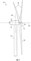
- FIG. 1 illustrates a perspective view of one embodiment of a wind turbine power system 10 (also referred to herein simply as wind turbine 10) according to the present disclosure.
- the wind turbine 10 described herein includes a horizontal-axis configuration, however, in some embodiments, the wind turbine 10 may include, in addition or alternative to the horizontal-axis configuration, a vertical-axis configuration (not shown).
- the wind turbine 10 may be coupled to an electrical load (not shown in FIG. 1 ), such as, but not limited to, a power grid, for receiving electrical power therefrom to drive operation of the wind turbine 10 and/or its associated components and/or for supplying electrical power generated by the wind turbine 10 thereto.
- the wind turbine 10 may include a nacelle 12 and a rotor (generally designated by 14) coupled to nacelle 12 for rotation with respect to nacelle 12 about an axis of rotation 20.
- the nacelle 12 is mounted on a tower 16, however, in some embodiments, in addition or alternative to the tower-mounted nacelle 12, the nacelle 12 may be positioned adjacent the ground and/or a surface of water.
- the rotor 14 includes a hub 22 and a plurality of rotor blades 24 extending radially outwardly from the hub 22 for converting wind energy into rotational energy.
- the rotor 14 is described and illustrated herein as having three rotor blades 24, the rotor 14 may have any number of rotor blades 24. Further, the rotor blades 24 may each have any length that allows the wind turbine 10 to function as described herein.
- the wind turbine 10 also includes an electrical generator 26 coupled to the rotor 14 for generating electrical power from the rotational energy generated by the rotor 14.
- the generator 26 may be any suitable type of electrical generator, such as, but not limited to, a wound rotor induction generator, a double-fed induction generator (DFIG, also known as dual-fed asynchronous generators), a permanent magnet (PM) synchronous generator, an electrically-excited synchronous generator, and a switched reluctance generator.
- the generator 26 includes a stator (not shown) and a rotor (not shown) with an air gap included therebetween.
- the rotor 14 includes a rotor shaft 28 coupled to the rotor hub 22 for rotation therewith.
- the generator 26 is coupled to the rotor shaft 28 such that rotation of the rotor shaft 28 drives rotation of the generator rotor, and therefore operation of the generator 26.
- the generator rotor has a generator shaft 30 coupled thereto and coupled to the rotor shaft 28 such that rotation of the rotor shaft 28 drives rotation of the generator rotor.
- the generator rotor is directly coupled to the rotor shaft 28, sometimes referred to as a "direct-drive wind turbine.”
- the generator shaft 30 is coupled to the rotor shaft 28 through a gearbox 32, although in other embodiments generator shaft 30 is coupled directly to rotor shaft 28.
- the torque of the rotor 14 drives the generator rotor to thereby generate variable frequency AC electrical power from rotation of rotor 14.
- the generator 26 has an air gap torque between the generator rotor and stator that opposes the torque of rotor 14.
- a power conversion assembly 34 is coupled to the generator 26 for converting the variable frequency AC to a fixed frequency AC for delivery to an electrical load (not shown in FIG. 2 ), such as, but not limited to a power grid (not shown in FIG. 2 ), coupled to the generator 26.
- the power conversion assembly 34 may include a single frequency converter or a plurality of frequency converters configured to convert electricity generated by the generator 26 to electricity suitable for delivery over the power grid.
- the power conversion assembly 34 may also be referred to herein as a power converter.
- the power conversion assembly 34 may be located anywhere within or remote to the wind turbine 10. For example, the power conversion assembly 34 may be located within a base (not shown) of the tower 16.
- the wind turbine 10 may include a rotor speed limiter, for example, but not limited to a disk brake 36.
- the disk brake 36 brakes rotation of the rotor 14 to, for example, slow rotation of the rotor 14, the brake rotor 14 against full wind torque, and/or reduce the generation of electrical power from the generator 26.
- the wind turbine 10 may include a yaw system 38 for rotating the nacelle 12 about an axis of rotation 40 for changing a yaw of rotor 14, and more specifically for changing a direction faced by the rotor 14 to, for example, adjust an angle between the direction faced by the rotor 14 and a direction of wind.
- the wind turbine 10 includes a variable blade pitch system 42 for controlling, including but not limited to changing, a pitch angle of blades 24 (shown in FIGS. 1-2 ) with respect to a wind direction.
- the pitch system 42 may be coupled to a controller 44 for control thereby.
- the pitch system 42 is coupled to the hub 22 and the rotor blades 24 for changing the pitch angle of blades 24 by rotating the rotor blades 24 with respect to the hub 22.
- the pitch actuators may include any suitable structure, configuration, arrangement, means, and/or components, whether described and/or shown herein, such as, but not limited to, electrical motors, hydraulic cylinders, springs, and/or servomechanisms.
- the pitch actuators may be driven by any suitable means, whether described and/or shown herein, such as, but not limited to, hydraulic fluid, electrical power, electro-chemical power, and/or mechanical power, such as, but not limited to, spring force.
- the wind turbine 10 includes one or more controllers 44 coupled to at least one component of wind turbine 10 for generally controlling operation of the wind turbine 10 and/or controlling operation of the components thereof, regardless of whether such components are described and/or shown herein.
- the controller 44 is coupled to the pitch system 42 for generally controlling the rotor 14.
- the controller 44 may be mounted within the nacelle 12 (as shown in FIG. 2 ), however, additionally or alternatively, one or more controllers 44 may be remote from the nacelle 12 and/or other components of the wind turbine 10.
- the controller(s) 44 may be used for overall system monitoring and control including, without limitation, pitch and speed regulation, high-speed shaft and yaw brake application, yaw and pump motor application, and/or fault monitoring. Alternative distributed or centralized control architectures may be used in some embodiments.
- the wind turbine 10 includes a plurality of sensors, for example, sensors 50, 52, 54, 56, 58 as shown in FIGS. 1 , 2 , and 4 .
- the sensors 50, 52, 54, 56, 58 are configured to measure a variety of parameters including, without limitation, operating conditions and atmospheric conditions.
- the wind turbine 10 includes a wind sensor 56, such as an anemometer or any other suitable device, configured for measuring wind speeds or any other wind parameter.
- the wind parameters include information regarding at least one of or a combination of the following: a wind gust, a wind speed, a wind direction, a wind acceleration, a wind turbulence, a wind shear, a wind veer, a wake, SCADA information, or similar.
- the wind turbine 10 may also include one or more additional sensors for monitoring additional operational parameters of the wind turbine 10.
- each sensor 50, 52, 54, 56, 58 may be an individual sensor or may include a plurality of sensors.
- the sensors 50, 52, 54, 56, 58 may be any suitable sensor having any suitable location within or remote to wind turbine 10 that allows the wind turbine 10 to function as described herein.
- the sensors 50, 52, 54, 56, 58 are coupled to one of the controllers 44, 94, 156 described herein for transmitting measurements to the controllers 44, 94, 156 for processing thereof.
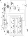
- the controller 44 may include a bus 62 or other communications device to communicate information. Further, one or more processor(s) 64 may be coupled to the bus 62 to process information, including information from the sensors 50, 52, 54, 56, 58 and/or other sensor(s).
- the processor(s) 64 may include at least one computer.
- the term computer is not limited to integrated circuits referred to in the art as a computer, but broadly refers to a processor, a microcontroller, a microcomputer, a programmable logic controller (PLC), an application specific integrated circuit, and other programmable circuits, and these terms are used interchangeably herein.
- the controller 44 may also include one or more random access memories (RAM) 66 and/or other storage device(s) 68.
- RAM random access memories
- the RAM(s) 66 and storage device(s) 68 may be coupled to the bus 62 to store and transfer information and instructions to be executed by processor(s) 64.
- the RAM(s) 66 (and/or storage device(s) 68, if included) can also be used to store temporary variables or other intermediate information during execution of instructions by the processor(s) 64.
- the controller 44 may also include one or more read only memories (ROM) 70 and/or other static storage devices coupled to the bus 62 to store and provide static (i.e., non-changing) information and instructions to the processor(s) 64.
- ROM read only memories
- the processor(s) 64 process information transmitted from a plurality of electrical and electronic devices that may include, without limitation, speed and power transducers. Instructions that are executed include, without limitation, resident conversion and/or comparator algorithms. The execution of sequences of instructions is not limited to any specific combination of hardware circuitry and software instructions.
- the controller 44 may also include, or may be coupled to, input/output device(s) 72.
- the input/output device(s) 72 may include any device known in the art to provide input data to the controller 44 and/or to provide outputs, such as, but not limited to, yaw control and/or pitch control outputs.
- Instructions may be provided to the RAM 66 from the storage device 68 including, for example, a magnetic disk, a read-only memory (ROM) integrated circuit, CD-ROM, and/or DVD, via a remote connection that is either wired or wireless providing access to one or more electronically-accessible media.
- ROM read-only memory
- DVD digital versatile discs
- hard-wired circuitry can be used in place of or in combination with software instructions.
- the input/output device(s) 72 may include, without limitation, computer peripherals associated with an operator interface such as a mouse and a keyboard (neither shown in FIG. 3 ). Alternatively, other computer peripherals may also be used that may include, for example, a scanner (not shown in FIG. 3 ). Furthermore, in one embodiment, additional output channels may include, for example, an operator interface monitor (not shown in FIG. 3 ).
- the controller 44 may also include a sensor interface 74 that allows controller 44 to communicate with the sensors 50, 52, 54, 56, 58 and/or other sensor(s).
- the sensor interface 74 may include one or more analog-to-digital converters that convert analog signals into digital signals that can be used by the processor(s) 64.
- the wind turbine 10 also includes a phase locked loop (PLL) 80.
- the PLL 80 is coupled to sensor 54.
- the sensor 54 is a voltage transducer configured to measure a terminal grid voltage output by frequency converter 34.
- the PLL 80 is configured to receive a plurality of voltage measurement signals from a plurality of voltage transducers.
- each of three voltage transducers is electrically coupled to each one of three phases of a grid bus.
- the PLL 80 may be configured to receive any number of voltage measurement signals from any number of voltage transducers that allow the PLL 80 to function as described herein.
- the wind turbine 10 described herein may be part of a wind farm 90 that is controlled according to the system and method of the present disclosure is illustrated.
- the wind farm 90 may include a plurality of wind turbines 92, including the wind turbine 10 described above, and a farm-level controller 94.
- the wind farm 90 includes twelve wind turbines, including wind turbine 10.
- the wind farm 90 may include any other number of wind turbines, such as less than twelve wind turbines or greater than twelve wind turbines.
- the controller 44 of the wind turbine 10 may be communicatively coupled to the farm-level controller 94 through a wired connection, such as by connecting the controller 44 through suitable communicative links 96 or networks (e.g., a suitable cable).
- the controller 44 may be communicatively coupled to the farm-level controller 94 through a wireless connection, such as by using any suitable wireless communications protocol known in the art.
- the farm-level controller 94 may be generally configured similar to the controllers 44 for each of the individual wind turbines 92 within the wind farm 90.
- the power generation and delivery system 150 includes an energy source, for example, the generator 26. Although described herein as the wind turbine generator 26, the energy source may include any type of electrical generator that allows the system 150 to function as described herein.
- the system 150 also includes a power converter, such as, the power converter 34.
- the power converter 34 receives variable frequency electrical power 132 generated by the generator 26 and converts electrical power 132 to an electrical power 134 (referred to herein as a terminal power 134) suitable for transmission over an electric power transmission and distribution grid 136 (referred to herein as utility grid 136).
- a terminal voltage (V t ) 138 is defined at a node between the power converter 34 and the utility grid 136.
- a load 140 is coupled to the utility grid 136 where a Thevenin voltage is defined.
- variable speed operation of the wind turbine 10 facilitates enhanced capture of energy when compared to a constant speed operation of the wind turbine 10, however, variable speed operation of the wind turbine 10 produces the electrical power 132 having varying voltage and/or frequency. More specifically, the frequency of the electrical power 132 generated by the variable speed generator 26 is proportional to the speed of rotation of the rotor 14 (shown in FIG. 1 ).
- the power converter 34 outputs the terminal power 134 having a substantially fixed voltage and frequency for delivery on the utility grid 136.
- the power converter 34 also controls an air gap torque of the generator 26.
- the air gap torque is present between the generator rotor (not shown in FIG. 3 ) and the generator stator (not shown in FIG. 3 ) and opposes the torque applied to the generator 26 by the rotor 14.
- a balance between a torque on the rotor 14 created by interaction of the rotor blades 24 and the wind and the air gap torque facilitates stable operation of the wind turbine 10.
- Wind turbine adjustments for example, blade pitch adjustments, or grid events, for example, low voltage transients or zero voltage transients on the utility grid 136, may cause an imbalance between the torque on the rotor 14 caused by the wind and the air gap torque.
- the power converter 34 controls the air gap torque which facilitates controlling the power output of the generator 26, however, the wind turbine 10 may not be able to operate through certain grid events, or may sustain wear and/or damage due to certain grid events, due to a time period required for adjustments to wind turbine operation to take effect after detecting the grid event.
- the system 150 may include a grid-dependent power limiter system 152.
- a controller for example, but not limited to, controller 44 (shown in FIG. 3 ), may be programmed to perform the functions of the grid-dependent power limiter system 152.
- the functions of the grid-dependent power limiter system 152 may be performed by any circuitry configured to allow the system 150 to function as described herein.
- the power limiter system 152 is configured to identify the occurrence of a grid contingency event, and provide the power converter 34 with signals that facilitate providing a stable recovery from the grid event.
- the power conversion assembly 34 is configured to receive control signals 154 from a converter interface controller 156.
- the control signals 154 are based on sensed operating conditions or operating characteristics of the wind turbine 10 as described herein and used to control the operation of the power conversion assembly 34. Examples of measured operating conditions may include, but are not limited to, a terminal grid voltage, a PLL error, a stator bus voltage, a rotor bus voltage, and/or a current.
- the sensor 54 measures terminal grid voltage 138 and transmits a terminal grid voltage feedback signal 160 to power limiter system 152.
- the power limiter system 152 generates a power command signal 162 based at least partially on the feedback signal 160 and transmits power command signal 162 to the converter interface controller 156.
- the converter interface controller 156 is included within the system controller 44. Other operating condition feedback from other sensors also may be used by the controller 44 and/or converter interface controller 156 to control the power conversion assembly 34.
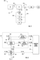
- FIG. 6 a block diagram of one embodiment of the power limiter system 152 of the wind turbine 10 according to the present disclosure is illustrated.
- the power limiter system 152 is configured to output the power command signal 162 (shown in FIG. 5 ), which in one embodiment, is at least one of a real current command signal 166 and a reactive current command signal 168.
- the power limiter system 152 includes a power limiter 180, a power regulator 182, and a voltage regulator 184.
- the power limiter 180 receives at least one measured operating condition of the system 150.
- the measured operating condition(s) may include, but is not limited to, a PLL error signal 190 (e.g. PLLERR) from the PLL 80 and the terminal grid voltage feedback signal 160 (e.g. VT_FBK) from the sensor 54.
- a PLL error signal 190 e.g. PLLERR
- VT_FBK terminal grid voltage feedback signal
- the power limiter 180 also receives a stored reference power control signal 194 (e.g. PREF) from, for example, the controller 44 ( FIG. 3 ).
- a stored reference power control signal 194 e.g. PREF
- the power limiter 180 receives the power limit control signal 224 and the reference power control signal 194 and generates the power command signal 198 corresponding to the lesser of the power limit control signal 224 and the reference power control signal 194.
- the power limiter 180 generates the power command signal 198 (e.g. PCMD) and transmits the power command signal 198 to the power regulator 182.
- the power regulator 182 then generates the real current command signal 166 and transmits the signal 166 to the converter interface controller 156.
- the real current command signal 166 instructs the converter interface controller 156 to modify a real component of current that the power conversion assembly 34 tries to inject onto the utility grid 136.
- the voltage regulator 184 generates the reactive current command signal 168 (e.g. IY_CMD) and sends the command signal 168 to the converter interface controller 156.
- the current command signal 168 instructs the converter interface controller 156 to modify a reactive component of current injected onto the utility grid 136.
- the converter interface controller 156 may also be referred to herein as a converter firing control.
- the PLL 80 may be included within the controller 44, or may be coupled to, but separate from, the controller 44.
- the PLL 80 also receives the terminal voltage feedback signal 160.
- the PLL 80 may receive the terminal voltage feedback signal 160 (shown in FIG. 3 as V t ) provided by the sensor 54 (shown in FIG. 3 ).
- the PLL 80 receives a PLL feedforward signal 192 (e.g. PLL_FF), which is described in more detail in reference to FIG. 7 below.
- the PLL 80 also generates the PLL error signal 190 (e.g. PLLERR) and a PLL phase angle signal 202 (e.g. TH_PLL).
- the PLL phase angle signal 202 is transmitted to the converter interface controller 156 for control of the power conversion assembly 34 and for subsequent control of electrical currents injected onto the utility grid 136 (shown in FIG. 5 ).
- the PLL 80 may generally include a demodulator 204 that receives the terminal voltage feedback signal 160.
- the demodulator 204 is configured to extract the phase error between the original terminal voltage feedback carrier wave (i.e. the voltage feedback signal 160) and the PLL angle.
- the demodulator 204 generates the PLL error signal 190 that is regulated via the PLL regulator 206.
- the PLL regulator 206 determines a frequency signal 208 (i.e. PLL_W) of the PLL 80 in response to the PLL error signal 190.
- the frequency signal 208 may then be integrated via integrator 210 of the PLL 80.
- the output signal 212 of the integrator 210 is then sent to function block 214.
- the PLL feedforward signal 192 (which may also be referred to herein as a power angle signal) may be estimated via a power angle estimator 216.
- the term "feedforward” encompasses its broadest interpretation, which generally describes an element or pathway within a control system that passes a controlling signal from a source in its external environment to a load elsewhere in its external environment.
- the power angle signal 192 is estimated external to the PLL 80 and then input into the PLL 80.
- the power angle estimator 216 is configured to estimate or calculate a power angle across the electrical power system (e.g. the wind turbine 10) based on the received power command PCMD 198 and/or one or more external grid conditions 218.
- the power angle (PA) may be estimated using a non-linear function.
- the non-linear function may include a polynomial or trigonometric function, such as but not limited to sine, cosine, or arcsine.
- the PLL 80 is configured to generate the PLL phase angle signal 202 based on the estimated feedforward power angle signal 192 and the output signal of the integrator 210. More specifically, as shown, the PLL 80 generates the PLL phase angle signal 202 by summing the estimated feedforward power angle signal 192 and the output signal 212 of the integrator 210. Thus, as shown in FIG. 6 , the converter controller 156 controls the power conversion assembly 34 based on the PLL phase angle signal.
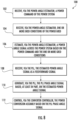
- the method 100 includes receiving, via the power angle estimator 216, the power command 198 of the wind turbine power system 10.
- the method 100 includes receiving, via the power angle estimator, one or more grid conditions of the power grid.
- the grid condition may include, but are not limited to information that can assist in estimating the reactance X between the two electric buses at or near the ends of the power system, such as breaker status or alternatively a priori knowledge of the nature of the power grid.
- the reactance of the grid may be known for a given project, in which case the parameter X can be set according to that a priori knowledge.
- Another example of such information may include knowing if a grid system may have one important transmission line that, if removed from service, will make a substantial change in the effective reactance.
- the effective reactance would be computed a-priori knowing the characteristics of the grid with and without that important line in service. Then, during operation the selection of reactance X in the power angle estimation would be toggled between the two precomputed values of X depending upon the status of the circuit breakers on that line.
- the method 100 includes estimating, via the power angle estimator 216, a power angle signal 192 across the power system based on the power command and/or the grid condition(s). As shown at 108, the method 100 includes receiving, via the PLL 80, the estimated power angle signal 192 as a feedforward signal. As shown at 110, the method 100 includes generating, via the PLL 80, the PLL phase angle signal 202 based, at least in part, on the estimated power angle signal 192. As shown at 112, the method 100 includes controlling, via the converter controller 156, the power conversion assembly 34 based on the PLL phase angle signal 202.
- the feedforward function of the present disclosure provides less lag between the actual power and the power command, particularly in weak grids operating at high power.
- Benefits of the feedforward function of the present disclosure may depend on how close the estimated power angle is to the actual characteristic of the AC transmission system. As mentioned, Equation (2) above indicates example operating parameters needed to derive the power angle described herein.
Landscapes
- Engineering & Computer Science (AREA)
- Power Engineering (AREA)
- Life Sciences & Earth Sciences (AREA)
- Sustainable Energy (AREA)
- Sustainable Development (AREA)
- Chemical & Material Sciences (AREA)
- Combustion & Propulsion (AREA)
- Mechanical Engineering (AREA)
- General Engineering & Computer Science (AREA)
- Control Of Eletrric Generators (AREA)
Claims (15)
- Verfahren zur Verringerung einer Verzögerung zwischen einem Leistungssollwert (198) und der tatsächlichen Leistung eines an ein Stromnetz (136) angeschlossenen Stromsystems (150), wobei das Verfahren Folgendes umfasst:Empfang eines Leistungsbefehls (198) des Stromversorgungssystems (150) über einen Leistungswinkelschätzer (216);Empfangen einer oder mehrerer Netzbedingungen (218) des Stromnetzes (136) über den Leistungswinkelschätzer (216);Schätzen eines Leistungswinkelsignals (192) über das Stromversorgungssystem (150) mittels des Leistungswinkelschätzers (216) auf der Grundlage des Leistungsbefehls (198) und der einen oder mehreren Netzbedingungen (218);dadurch gekennzeichnet, dass das Verfahren ferner umfasst:Empfang des geschätzten Leistungswinkelsignals (192) über einen Phasenregelkreis PLL (80);Erzeugen eines PLL-Phasenwinkelsignals (202) über den PLL (80), das zumindest teilweise auf dem geschätzten Leistungswinkelsignal (192) basiert; und,Steuerung einer Leistungsumwandlungseinheit (34) des Leistungssystems (150) über einen Umrichterregler (156) auf der Grundlage des PLL-Phasenwinkelsignals (202).
- Verfahren nach Anspruch 1, das ferner den Empfang des Leistungswinkelsignals (192) über den PLL (80) als Vorwärtssignal umfasst.
- Verfahren nach Anspruch 1 oder 2, wobei das Schätzen des Leistungswinkelsignals (192) über das Stromversorgungssystem (150) ferner umfasst:
Berechnung des Leistungswinkelsignals (192) als Funktion einer übertragenen Leistung und einer Reaktanz zwischen zwei elektrischen Bussen an oder in der Nähe der Enden des Stromnetzes (150). - Verfahren nach Anspruch 3, wobei das Schätzen des Leistungswinkelsignals (192) über das Stromversorgungssystem (150) weiterhin umfasst:
Berechnung des Leistungswinkelsignals (192) als Funktion der übertragenen Leistung, der Spannungsgrößen an den beiden Enden des Stromnetzes (150) und der Reaktanz zwischen zwei elektrischen Bussen an oder nahe den Enden des Stromnetzes (150). - Das Verfahren nach Anspruch 4, weiter umfassend die Berechnung des Leistungswinkelsignals (192) als nichtlineare Funktion der übertragenen Leistung, der Spannungsgrößen an den beiden Enden des Stromversorgungssystems (150) und der Reaktanz zwischen den beiden elektrischen Bussen an oder nahe den Enden des Stromversorgungssystems (150).
- Verfahren nach Anspruch 5, wobei das Berechnen des Leistungswinkelsignals (192) als Funktion der übertragenen Leistung, der Spannungsgrößen an den beiden Enden des Stromversorgungssystems (150) und der Reaktanz zwischen den beiden elektrischen Bussen an den oder in der Nähe der Enden des Stromversorgungssystems (150) weiterhin umfasst:Multiplikation der Spannungsgrößen an den beiden Enden des Stromnetzes (150), um einen ersten multiplizierten Wert zu erhalten;Dividieren der Reaktanz zwischen den beiden elektrischen Bussen an oder nahe den Enden des Stromnetzes (150) durch den ersten multiplizierten Wert, um einen Multiplikator zu erhalten;Multiplizieren der übertragenen Leistung mit dem Multiplikator, um einen zweiten multiplizierten Wert zu erhalten; und,Anwendung einer nichtlinearen Funktion auf den zweiten multiplizierten Wert.
- Verfahren nach Anspruch 5, wobei die nichtlineare Funktion ein Polynom, ein Sinus, ein Kosinus und/oder ein Bogensinus umfasst.
- Verfahren nach einem der vorhergehenden Ansprüche, wobei das Erzeugen des PLL-Phasenwinkelsignals (202) zumindest teilweise auf der Grundlage des geschätzten Leistungswinkelsignals (192) weiterhin umfasst:Empfang eines Rückkopplungssignals der Klemmengitterspannung;Bestimmung eines PLL-Fehlersignals (190) auf der Grundlage des Rückkopplungssignals der Klemmengitterspannung;Bestimmen eines Frequenzsignals (208) des PLL (80) über einen PLL-Regler (206) in Reaktion auf das PLL-Fehlersignal (190);Integrieren des Frequenzsignals (208) über einen Integrator (210) des PLL, um ein Ausgangssignal zu erhalten; und,Erzeugen des PLL-Phasenwinkelsignals (202) basierend auf dem Ausgangssignal und dem Leistungswinkelsignal (192).
- Verfahren nach Anspruch 8, wobei das Erzeugen des PLL-Phasenwinkelsignals (202) auf der Grundlage des Ausgangssignals und des Leistungswinkelsignals (192) ferner das Addieren des Ausgangssignals und des Leistungswinkelsignals (192) umfasst.
- Verfahren nach einem der vorhergehenden Ansprüche, wobei das Energiesystem (150) mindestens eines der folgenden Systeme umfasst: ein Windturbinen-Energiesystem, ein Solarenergiesystem oder ein Energiespeichersystem.
- Elektrisches Energiesystem (150), das mit einem Stromnetz (136) verbunden ist und Folgendes umfasst:einen elektrischen Generator (26);eine Leistungsumwandlungseinheit (34), die mit dem elektrischen Generator (26) gekoppelt ist, wobei die Leistungsumwandlungseinheit (34) so konfiguriert ist, dass sie von dem elektrischen Generator (26) erzeugte Leistung empfängt und die empfangene Leistung in eine Leistung umwandelt, die zur Übertragung an das Stromnetz (136) geeignet ist;einen Leistungswinkelschätzer (216), der so konfiguriert ist, dass er ein Leistungswinkelsignal (192) über das elektrische Energiesystem (150) auf der Grundlage eines empfangenen Leistungsbefehls (198) und einer oder mehrerer Netzbedingungen (218) des Stromnetzes (136) schätzt;dadurch gekennzeichnet, dass das elektrische Energiesystem weiterhin umfasst:einen Phasenregelkreis, PLL (80), der so konfiguriert ist, dass er ein PLL-Phasenwinkelsignal (202) zumindest teilweise auf der Grundlage des geschätzten Leistungswinkelsignals (192) erzeugt; und,eine Wandlersteuerung (156) zum Steuern der Leistungsumwandlungseinheit (34) auf der Grundlage des PLL-Phasenwinkelsignals (202).
- Elektrisches Energiesystem (150) nach Anspruch 11, wobei der PLL so konfiguriert ist, dass er das Leistungswinkelsignal (192) als Vorwärtssignal empfängt.
- Elektrisches Stromversorgungssystem (150) nach Anspruch 11 oder 12, wobei der Leistungswinkelschätzer (216) so konfiguriert ist, dass er das Leistungswinkelsignal (192) über das Stromversorgungssystem (150) schätzt, indem er das Leistungswinkelsignal (192) als eine Funktion einer übertragenen Leistung, von Spannungsgrößen an zwei Enden des Stromversorgungssystems (150) und/oder der Reaktanz zwischen den beiden elektrischen Bussen an oder nahe den Enden des Stromversorgungssystems (150) berechnet.
- Elektrisches Energiesystem (150) nach Anspruch 13, wobei der Leistungswinkelschätzer (216) so konfiguriert ist, dass er das Leistungswinkelsignal (192) als eine nichtlineare Funktion der übertragenen Leistung, der Spannungsgrößen an den beiden Enden des Energiesystems (150) und der Reaktanz zwischen den beiden elektrischen Bussen an oder nahe den Enden des Energiesystems (150) berechnet.
- Elektrisches Energiesystem (150) nach Anspruch 11, 12, 13 oder 14, wobei der PLL so konfiguriert ist, dass er das PLL-Phasenwinkelsignal (202) zumindest teilweise auf der Grundlage des geschätzten Leistungswinkelsignals (192) erzeugt, indem sie:Empfang eines Rückkopplungssignals der Klemmengitterspannung;Bestimmung eines PLL-Fehlersignals (190) auf der Grundlage des Rückkopplungssignals der Klemmengitterspannung;Bestimmen eines Frequenzsignals (208) des PLL über einen PLL-Regulator des PLL in Reaktion auf das PLL-Fehlersignal (190);Integrieren des Frequenzsignals (208) über einen Integrator (210) des PLL, um ein Ausgangssignal zu erhalten; und,Erzeugen des PLL-Phasenwinkelsignals (202) basierend auf dem Ausgangssignal und dem Leistungswinkelsignal (192) durch Addieren des Ausgangssignals und des Leistungswinkelsignals (192).
Applications Claiming Priority (2)
| Application Number | Priority Date | Filing Date | Title |
|---|---|---|---|
| US15/902,184 US10305283B1 (en) | 2018-02-22 | 2018-02-22 | Power angle feedforward signal for phase locked loop in wind turbine power systems |
| PCT/US2019/018468 WO2019164792A1 (en) | 2018-02-22 | 2019-02-19 | Power angle feedforward signal for phase locked loop in wind turbine power systems |
Publications (3)
| Publication Number | Publication Date |
|---|---|
| EP3755901A1 EP3755901A1 (de) | 2020-12-30 |
| EP3755901A4 EP3755901A4 (de) | 2021-11-24 |
| EP3755901B1 true EP3755901B1 (de) | 2024-10-30 |
Family
ID=66636454
Family Applications (1)
| Application Number | Title | Priority Date | Filing Date |
|---|---|---|---|
| EP19757424.7A Active EP3755901B1 (de) | 2018-02-22 | 2019-02-19 | Leistungswinkelvorwärtskopplungssignal für phasenregelschleife in windkraftanlagen |
Country Status (6)
| Country | Link |
|---|---|
| US (1) | US10305283B1 (de) |
| EP (1) | EP3755901B1 (de) |
| CN (1) | CN111712634B (de) |
| DK (1) | DK3755901T3 (de) |
| ES (1) | ES3008833T3 (de) |
| WO (1) | WO2019164792A1 (de) |
Families Citing this family (4)
| Publication number | Priority date | Publication date | Assignee | Title |
|---|---|---|---|---|
| CN110333732A (zh) * | 2019-07-22 | 2019-10-15 | 深圳市道通智能航空技术有限公司 | 云台电机控制方法及其装置、云台及无人飞行器 |
| US12212271B2 (en) | 2020-01-16 | 2025-01-28 | Ge Infrastructure Technology Llc | System and method for providing grid-forming control for a double-fed wind turbine generator |
| US11624350B2 (en) * | 2020-09-18 | 2023-04-11 | General Electric Company | System and method for providing grid-forming control of an inverter-based resource |
| US11456645B2 (en) * | 2020-12-10 | 2022-09-27 | General Electric Renovables Espana, S.L. | System and method for operating an asynchronous inverter-based resource as a virtual synchronous machine with storage |
Family Cites Families (32)
| Publication number | Priority date | Publication date | Assignee | Title |
|---|---|---|---|---|
| US4994684A (en) | 1989-01-30 | 1991-02-19 | The State Of Oregon Acting By And Through The State Board Of Higher Education On Behalf Of Oregon State University | Doubly fed generator variable speed generation control system |
| US7119452B2 (en) | 2003-09-03 | 2006-10-10 | General Electric Company | Voltage control for wind generators |
| JP4269941B2 (ja) | 2004-01-08 | 2009-05-27 | 株式会社日立製作所 | 風力発電装置およびその制御方法 |
| US7312537B1 (en) | 2006-06-19 | 2007-12-25 | General Electric Company | Methods and apparatus for supplying and/or absorbing reactive power |
| ES2552058T3 (es) | 2006-10-19 | 2015-11-25 | Siemens Aktiengesellschaft | Instalación de energía eólica y método para controlar la potencia de salida de una instalación de energía eólica |
| US7629705B2 (en) | 2006-10-20 | 2009-12-08 | General Electric Company | Method and apparatus for operating electrical machines |
| US7642666B2 (en) | 2006-11-02 | 2010-01-05 | Hitachi, Ltd. | Wind power generation apparatus, wind power generation system and power system control apparatus |
| EP2003759B1 (de) * | 2007-06-14 | 2020-03-04 | SMA Solar Technology AG | Verfahren zur Inselnetzerkennung |
| DE102009017939A1 (de) | 2009-04-17 | 2010-11-11 | Nordex Energy Gmbh | Windpark mit mehreren Windenergieanlagen sowie Verfahren zur Regelung der Einspeisung von einem Windpark |
| BRPI0909215A2 (pt) | 2009-05-01 | 2015-08-25 | Mitsubishi Heavy Ind Ltd | Aparelho de geração e método de controle do mesmo |
| US8328514B2 (en) | 2009-09-11 | 2012-12-11 | General Electric Company | System and methods for determining a monitor set point limit for a wind turbine |
| US8025476B2 (en) | 2009-09-30 | 2011-09-27 | General Electric Company | System and methods for controlling a wind turbine |
| US8860236B2 (en) | 2009-10-19 | 2014-10-14 | Uwm Research Foundation, Inc. | Wind energy power conversion system reducing gearbox stress and improving power stability |
| WO2011050807A2 (en) | 2009-10-27 | 2011-05-05 | Vestas Wind Systems A/S | Wind power plant with optimal power output |
| US8692523B2 (en) * | 2009-11-04 | 2014-04-08 | General Electric Company | Power generation system and method with voltage fault ride-through capability |
| US8046109B2 (en) | 2009-12-16 | 2011-10-25 | General Electric Company | Method and systems for operating a wind turbine |
| EP2577831B1 (de) * | 2010-06-03 | 2019-03-06 | Vestas Wind Systems A/S | Verfahren und steueranordnung zur steuerung der zentralen kondensatoren bei windenergieanlagen |
| US9093924B2 (en) * | 2010-08-18 | 2015-07-28 | Vestas Wind Systems A/S | Method of controlling a grid side converter of a wind turbine and system suitable therefore |
| JP5580147B2 (ja) * | 2010-08-31 | 2014-08-27 | オリジン電気株式会社 | 安定化制御方法 |
| CN101924371B (zh) | 2010-09-08 | 2012-07-25 | 株洲变流技术国家工程研究中心有限公司 | 一种混合型电能质量治理方法 |
| KR101147206B1 (ko) * | 2010-10-06 | 2012-05-25 | 삼성에스디아이 주식회사 | 계통 연계형 전력 저장 시스템 및 이를 위한 통합 제어기 |
| US9728969B2 (en) * | 2011-05-31 | 2017-08-08 | Vestas Wind Systems A/S | Systems and methods for generating an inertial response to a change in the voltage of an electricial grid |
| EP2731223B1 (de) * | 2011-07-08 | 2016-06-08 | Kawasaki Jukogyo Kabushiki Kaisha | Stromumwandlungsvorrichtung für ein kombinationskraftwerk |
| US9711964B2 (en) | 2011-09-26 | 2017-07-18 | General Electric Corporation | Method and system for operating a power generation and delivery system |
| KR101699410B1 (ko) * | 2012-12-27 | 2017-01-24 | 카와사키 주코교 카부시키 카이샤 | 전력 변환 장치를 구비한 복합 발전 시스템 |
| US9859828B2 (en) * | 2013-02-07 | 2018-01-02 | Vestas Wind Systems A/S | Power plant and energy storage system for provision of grid ancillary services |
| JP6084863B2 (ja) * | 2013-02-28 | 2017-02-22 | 川崎重工業株式会社 | 系統連系する電力変換装置 |
| CN104104221B (zh) | 2013-04-11 | 2017-05-17 | 通用电气公司 | 具有有功无功功率解耦补偿机制的能量转换系统和方法 |
| US9541062B2 (en) * | 2013-11-20 | 2017-01-10 | Siemens Aktiengesellschaft | Method of operating a wind park |
| KR101809787B1 (ko) * | 2015-03-10 | 2017-12-15 | 엘에스산전 주식회사 | 배터리 전력 공급 시스템을 포함하는 전력 공급 시스템 |
| US9970417B2 (en) * | 2016-04-14 | 2018-05-15 | General Electric Company | Wind converter control for weak grid |
| CN109314395B (zh) * | 2016-06-13 | 2022-07-05 | 维斯塔斯风力系统集团公司 | 与多个可再生能源发电厂的互连有关的改进 |
-
2018
- 2018-02-22 US US15/902,184 patent/US10305283B1/en active Active
-
2019
- 2019-02-19 CN CN201980014728.0A patent/CN111712634B/zh active Active
- 2019-02-19 DK DK19757424.7T patent/DK3755901T3/da active
- 2019-02-19 ES ES19757424T patent/ES3008833T3/es active Active
- 2019-02-19 EP EP19757424.7A patent/EP3755901B1/de active Active
- 2019-02-19 WO PCT/US2019/018468 patent/WO2019164792A1/en not_active Ceased
Also Published As
| Publication number | Publication date |
|---|---|
| ES3008833T3 (en) | 2025-03-25 |
| DK3755901T3 (da) | 2024-11-25 |
| EP3755901A4 (de) | 2021-11-24 |
| CN111712634B (zh) | 2023-04-21 |
| EP3755901A1 (de) | 2020-12-30 |
| CN111712634A (zh) | 2020-09-25 |
| WO2019164792A1 (en) | 2019-08-29 |
| US10305283B1 (en) | 2019-05-28 |
Similar Documents
| Publication | Publication Date | Title |
|---|---|---|
| EP2336554B1 (de) | Systeme zum Betrieb einer Windturbine | |
| US9453497B2 (en) | Method for operating a wind farm | |
| CA2833894C (en) | Method and systems for operating a wind turbine when recovering from a grid contingency event | |
| EP2658112B1 (de) | Verfahren und Systeme zur Steuerung eines Stromwandlers | |
| EP2573894B1 (de) | Verfahren und Systeme für den Betrieb eines Stromerzeugungs- und -versorgungssystems | |
| Beltran et al. | High-order sliding mode control of a DFIG-based wind turbine for power maximization and grid fault tolerance | |
| EP3755901B1 (de) | Leistungswinkelvorwärtskopplungssignal für phasenregelschleife in windkraftanlagen | |
| AU2013209323B2 (en) | Methods and systems for controlling a power converter | |
| CN111936740B (zh) | 用于功率系统的无功电流裕度调节器 | |
| US20220271695A1 (en) | System and method for providing grid-forming control for a double-fed wind turbine generator | |
| EP4662760A1 (de) | Netzbildende inselerkennung und kontinuierlicher betrieb einer wechselrichterbasierten ressource | |
| CN120153546A (zh) | 用于在电网形成型基于逆变器的资源中提供速度相关的电网频率支持的系统及方法 |
Legal Events
| Date | Code | Title | Description |
|---|---|---|---|
| STAA | Information on the status of an ep patent application or granted ep patent |
Free format text: STATUS: THE INTERNATIONAL PUBLICATION HAS BEEN MADE |
|
| PUAI | Public reference made under article 153(3) epc to a published international application that has entered the european phase |
Free format text: ORIGINAL CODE: 0009012 |
|
| STAA | Information on the status of an ep patent application or granted ep patent |
Free format text: STATUS: REQUEST FOR EXAMINATION WAS MADE |
|
| 17P | Request for examination filed |
Effective date: 20200922 |
|
| AK | Designated contracting states |
Kind code of ref document: A1 Designated state(s): AL AT BE BG CH CY CZ DE DK EE ES FI FR GB GR HR HU IE IS IT LI LT LU LV MC MK MT NL NO PL PT RO RS SE SI SK SM TR |
|
| AX | Request for extension of the european patent |
Extension state: BA ME |
|
| DAV | Request for validation of the european patent (deleted) | ||
| DAX | Request for extension of the european patent (deleted) | ||
| A4 | Supplementary search report drawn up and despatched |
Effective date: 20211027 |
|
| RIC1 | Information provided on ipc code assigned before grant |
Ipc: H03L 7/08 20060101ALI20211021BHEP Ipc: H02P 9/00 20060101ALI20211021BHEP Ipc: H02J 13/00 20060101ALI20211021BHEP Ipc: H02J 3/18 20060101ALI20211021BHEP Ipc: H02J 3/38 20060101ALI20211021BHEP Ipc: F03D 7/02 20060101AFI20211021BHEP |
|
| P01 | Opt-out of the competence of the unified patent court (upc) registered |
Effective date: 20230530 |
|
| GRAP | Despatch of communication of intention to grant a patent |
Free format text: ORIGINAL CODE: EPIDOSNIGR1 |
|
| STAA | Information on the status of an ep patent application or granted ep patent |
Free format text: STATUS: GRANT OF PATENT IS INTENDED |
|
| INTG | Intention to grant announced |
Effective date: 20230718 |
|
| GRAJ | Information related to disapproval of communication of intention to grant by the applicant or resumption of examination proceedings by the epo deleted |
Free format text: ORIGINAL CODE: EPIDOSDIGR1 |
|
| STAA | Information on the status of an ep patent application or granted ep patent |
Free format text: STATUS: REQUEST FOR EXAMINATION WAS MADE |
|
| RAP1 | Party data changed (applicant data changed or rights of an application transferred) |
Owner name: GENERAL ELECTRIC RENOVABLES ESPANA, S.L. |
|
| INTC | Intention to grant announced (deleted) | ||
| GRAP | Despatch of communication of intention to grant a patent |
Free format text: ORIGINAL CODE: EPIDOSNIGR1 |
|
| STAA | Information on the status of an ep patent application or granted ep patent |
Free format text: STATUS: GRANT OF PATENT IS INTENDED |
|
| INTG | Intention to grant announced |
Effective date: 20240117 |
|
| GRAJ | Information related to disapproval of communication of intention to grant by the applicant or resumption of examination proceedings by the epo deleted |
Free format text: ORIGINAL CODE: EPIDOSDIGR1 |
|
| STAA | Information on the status of an ep patent application or granted ep patent |
Free format text: STATUS: REQUEST FOR EXAMINATION WAS MADE |
|
| INTC | Intention to grant announced (deleted) | ||
| GRAP | Despatch of communication of intention to grant a patent |
Free format text: ORIGINAL CODE: EPIDOSNIGR1 |
|
| STAA | Information on the status of an ep patent application or granted ep patent |
Free format text: STATUS: GRANT OF PATENT IS INTENDED |
|
| INTG | Intention to grant announced |
Effective date: 20240528 |
|
| GRAS | Grant fee paid |
Free format text: ORIGINAL CODE: EPIDOSNIGR3 |
|
| GRAA | (expected) grant |
Free format text: ORIGINAL CODE: 0009210 |
|
| STAA | Information on the status of an ep patent application or granted ep patent |
Free format text: STATUS: THE PATENT HAS BEEN GRANTED |
|
| AK | Designated contracting states |
Kind code of ref document: B1 Designated state(s): AL AT BE BG CH CY CZ DE DK EE ES FI FR GB GR HR HU IE IS IT LI LT LU LV MC MK MT NL NO PL PT RO RS SE SI SK SM TR |
|
| REG | Reference to a national code |
Ref country code: GB Ref legal event code: FG4D |
|
| REG | Reference to a national code |
Ref country code: CH Ref legal event code: EP |
|
| REG | Reference to a national code |
Ref country code: IE Ref legal event code: FG4D |
|
| REG | Reference to a national code |
Ref country code: DE Ref legal event code: R096 Ref document number: 602019061144 Country of ref document: DE |
|
| REG | Reference to a national code |
Ref country code: DK Ref legal event code: T3 Effective date: 20241119 |
|
| REG | Reference to a national code |
Ref country code: LT Ref legal event code: MG9D |
|
| REG | Reference to a national code |
Ref country code: NL Ref legal event code: MP Effective date: 20241030 |
|
| REG | Reference to a national code |
Ref country code: ES Ref legal event code: FG2A Ref document number: 3008833 Country of ref document: ES Kind code of ref document: T3 Effective date: 20250325 |
|
| PG25 | Lapsed in a contracting state [announced via postgrant information from national office to epo] |
Ref country code: IS Free format text: LAPSE BECAUSE OF FAILURE TO SUBMIT A TRANSLATION OF THE DESCRIPTION OR TO PAY THE FEE WITHIN THE PRESCRIBED TIME-LIMIT Effective date: 20250228 Ref country code: HR Free format text: LAPSE BECAUSE OF FAILURE TO SUBMIT A TRANSLATION OF THE DESCRIPTION OR TO PAY THE FEE WITHIN THE PRESCRIBED TIME-LIMIT Effective date: 20241030 Ref country code: PT Free format text: LAPSE BECAUSE OF FAILURE TO SUBMIT A TRANSLATION OF THE DESCRIPTION OR TO PAY THE FEE WITHIN THE PRESCRIBED TIME-LIMIT Effective date: 20250228 |
|
| PGFP | Annual fee paid to national office [announced via postgrant information from national office to epo] |
Ref country code: DE Payment date: 20250122 Year of fee payment: 7 |
|
| PG25 | Lapsed in a contracting state [announced via postgrant information from national office to epo] |
Ref country code: FI Free format text: LAPSE BECAUSE OF FAILURE TO SUBMIT A TRANSLATION OF THE DESCRIPTION OR TO PAY THE FEE WITHIN THE PRESCRIBED TIME-LIMIT Effective date: 20241030 Ref country code: NL Free format text: LAPSE BECAUSE OF FAILURE TO SUBMIT A TRANSLATION OF THE DESCRIPTION OR TO PAY THE FEE WITHIN THE PRESCRIBED TIME-LIMIT Effective date: 20241030 |
|
| PGFP | Annual fee paid to national office [announced via postgrant information from national office to epo] |
Ref country code: DK Payment date: 20250121 Year of fee payment: 7 |
|
| REG | Reference to a national code |
Ref country code: AT Ref legal event code: MK05 Ref document number: 1737086 Country of ref document: AT Kind code of ref document: T Effective date: 20241030 |
|
| PG25 | Lapsed in a contracting state [announced via postgrant information from national office to epo] |
Ref country code: BG Free format text: LAPSE BECAUSE OF FAILURE TO SUBMIT A TRANSLATION OF THE DESCRIPTION OR TO PAY THE FEE WITHIN THE PRESCRIBED TIME-LIMIT Effective date: 20241030 |
|
| PGFP | Annual fee paid to national office [announced via postgrant information from national office to epo] |
Ref country code: ES Payment date: 20250303 Year of fee payment: 7 |
|
| PG25 | Lapsed in a contracting state [announced via postgrant information from national office to epo] |
Ref country code: NO Free format text: LAPSE BECAUSE OF FAILURE TO SUBMIT A TRANSLATION OF THE DESCRIPTION OR TO PAY THE FEE WITHIN THE PRESCRIBED TIME-LIMIT Effective date: 20250130 |
|
| PG25 | Lapsed in a contracting state [announced via postgrant information from national office to epo] |
Ref country code: AT Free format text: LAPSE BECAUSE OF FAILURE TO SUBMIT A TRANSLATION OF THE DESCRIPTION OR TO PAY THE FEE WITHIN THE PRESCRIBED TIME-LIMIT Effective date: 20241030 Ref country code: GR Free format text: LAPSE BECAUSE OF FAILURE TO SUBMIT A TRANSLATION OF THE DESCRIPTION OR TO PAY THE FEE WITHIN THE PRESCRIBED TIME-LIMIT Effective date: 20250131 Ref country code: LV Free format text: LAPSE BECAUSE OF FAILURE TO SUBMIT A TRANSLATION OF THE DESCRIPTION OR TO PAY THE FEE WITHIN THE PRESCRIBED TIME-LIMIT Effective date: 20241030 |
|
| PG25 | Lapsed in a contracting state [announced via postgrant information from national office to epo] |
Ref country code: PL Free format text: LAPSE BECAUSE OF FAILURE TO SUBMIT A TRANSLATION OF THE DESCRIPTION OR TO PAY THE FEE WITHIN THE PRESCRIBED TIME-LIMIT Effective date: 20241030 |
|
| PG25 | Lapsed in a contracting state [announced via postgrant information from national office to epo] |
Ref country code: RS Free format text: LAPSE BECAUSE OF FAILURE TO SUBMIT A TRANSLATION OF THE DESCRIPTION OR TO PAY THE FEE WITHIN THE PRESCRIBED TIME-LIMIT Effective date: 20250130 |
|
| PG25 | Lapsed in a contracting state [announced via postgrant information from national office to epo] |
Ref country code: SM Free format text: LAPSE BECAUSE OF FAILURE TO SUBMIT A TRANSLATION OF THE DESCRIPTION OR TO PAY THE FEE WITHIN THE PRESCRIBED TIME-LIMIT Effective date: 20241030 |
|
| PG25 | Lapsed in a contracting state [announced via postgrant information from national office to epo] |
Ref country code: EE Free format text: LAPSE BECAUSE OF FAILURE TO SUBMIT A TRANSLATION OF THE DESCRIPTION OR TO PAY THE FEE WITHIN THE PRESCRIBED TIME-LIMIT Effective date: 20241030 |
|
| PG25 | Lapsed in a contracting state [announced via postgrant information from national office to epo] |
Ref country code: RO Free format text: LAPSE BECAUSE OF FAILURE TO SUBMIT A TRANSLATION OF THE DESCRIPTION OR TO PAY THE FEE WITHIN THE PRESCRIBED TIME-LIMIT Effective date: 20241030 |
|
| PG25 | Lapsed in a contracting state [announced via postgrant information from national office to epo] |
Ref country code: SK Free format text: LAPSE BECAUSE OF FAILURE TO SUBMIT A TRANSLATION OF THE DESCRIPTION OR TO PAY THE FEE WITHIN THE PRESCRIBED TIME-LIMIT Effective date: 20241030 |
|
| PG25 | Lapsed in a contracting state [announced via postgrant information from national office to epo] |
Ref country code: CZ Free format text: LAPSE BECAUSE OF FAILURE TO SUBMIT A TRANSLATION OF THE DESCRIPTION OR TO PAY THE FEE WITHIN THE PRESCRIBED TIME-LIMIT Effective date: 20241030 |
|
| PG25 | Lapsed in a contracting state [announced via postgrant information from national office to epo] |
Ref country code: IT Free format text: LAPSE BECAUSE OF FAILURE TO SUBMIT A TRANSLATION OF THE DESCRIPTION OR TO PAY THE FEE WITHIN THE PRESCRIBED TIME-LIMIT Effective date: 20241030 |
|
| REG | Reference to a national code |
Ref country code: DE Ref legal event code: R097 Ref document number: 602019061144 Country of ref document: DE |
|
| PLBE | No opposition filed within time limit |
Free format text: ORIGINAL CODE: 0009261 |
|
| STAA | Information on the status of an ep patent application or granted ep patent |
Free format text: STATUS: NO OPPOSITION FILED WITHIN TIME LIMIT |
|
| PG25 | Lapsed in a contracting state [announced via postgrant information from national office to epo] |
Ref country code: SE Free format text: LAPSE BECAUSE OF FAILURE TO SUBMIT A TRANSLATION OF THE DESCRIPTION OR TO PAY THE FEE WITHIN THE PRESCRIBED TIME-LIMIT Effective date: 20241030 |
|
| PG25 | Lapsed in a contracting state [announced via postgrant information from national office to epo] |
Ref country code: MC Free format text: LAPSE BECAUSE OF FAILURE TO SUBMIT A TRANSLATION OF THE DESCRIPTION OR TO PAY THE FEE WITHIN THE PRESCRIBED TIME-LIMIT Effective date: 20241030 |
|
| REG | Reference to a national code |
Ref country code: CH Ref legal event code: PL |
|
| 26N | No opposition filed |
Effective date: 20250731 |
|
| PG25 | Lapsed in a contracting state [announced via postgrant information from national office to epo] |
Ref country code: LU Free format text: LAPSE BECAUSE OF NON-PAYMENT OF DUE FEES Effective date: 20250219 |
|
| PG25 | Lapsed in a contracting state [announced via postgrant information from national office to epo] |
Ref country code: CH Free format text: LAPSE BECAUSE OF NON-PAYMENT OF DUE FEES Effective date: 20250228 |
|
| GBPC | Gb: european patent ceased through non-payment of renewal fee |
Effective date: 20250219 |
|
| REG | Reference to a national code |
Ref country code: BE Ref legal event code: MM Effective date: 20250228 |
|
| PG25 | Lapsed in a contracting state [announced via postgrant information from national office to epo] |
Ref country code: GB Free format text: LAPSE BECAUSE OF NON-PAYMENT OF DUE FEES Effective date: 20250219 |
|
| PG25 | Lapsed in a contracting state [announced via postgrant information from national office to epo] |
Ref country code: FR Free format text: LAPSE BECAUSE OF NON-PAYMENT OF DUE FEES Effective date: 20250228 |
|
| PG25 | Lapsed in a contracting state [announced via postgrant information from national office to epo] |
Ref country code: BE Free format text: LAPSE BECAUSE OF NON-PAYMENT OF DUE FEES Effective date: 20250228 |
|
| PG25 | Lapsed in a contracting state [announced via postgrant information from national office to epo] |
Ref country code: IE Free format text: LAPSE BECAUSE OF NON-PAYMENT OF DUE FEES Effective date: 20250219 |