EP3755510B1 - Messeranordnung und damit ausgestattetes schneidsystem - Google Patents
Messeranordnung und damit ausgestattetes schneidsystem Download PDFInfo
- Publication number
- EP3755510B1 EP3755510B1 EP19705188.1A EP19705188A EP3755510B1 EP 3755510 B1 EP3755510 B1 EP 3755510B1 EP 19705188 A EP19705188 A EP 19705188A EP 3755510 B1 EP3755510 B1 EP 3755510B1
- Authority
- EP
- European Patent Office
- Prior art keywords
- knife
- holder
- knife blade
- clamp
- clamping
- Prior art date
- Legal status (The legal status is an assumption and is not a legal conclusion. Google has not performed a legal analysis and makes no representation as to the accuracy of the status listed.)
- Active
Links
Images


Classifications
-
- B—PERFORMING OPERATIONS; TRANSPORTING
- B26—HAND CUTTING TOOLS; CUTTING; SEVERING
- B26D—CUTTING; DETAILS COMMON TO MACHINES FOR PERFORATING, PUNCHING, CUTTING-OUT, STAMPING-OUT OR SEVERING
- B26D7/00—Details of apparatus for cutting, cutting-out, stamping-out, punching, perforating, or severing by means other than cutting
- B26D7/26—Means for mounting or adjusting the cutting member; Means for adjusting the stroke of the cutting member
- B26D7/2614—Means for mounting the cutting member
-
- B—PERFORMING OPERATIONS; TRANSPORTING
- B26—HAND CUTTING TOOLS; CUTTING; SEVERING
- B26D—CUTTING; DETAILS COMMON TO MACHINES FOR PERFORATING, PUNCHING, CUTTING-OUT, STAMPING-OUT OR SEVERING
- B26D7/00—Details of apparatus for cutting, cutting-out, stamping-out, punching, perforating, or severing by means other than cutting
- B26D7/06—Arrangements for feeding or delivering work of other than sheet, web, or filamentary form
- B26D7/0691—Arrangements for feeding or delivering work of other than sheet, web, or filamentary form by centrifugal force
-
- B—PERFORMING OPERATIONS; TRANSPORTING
- B26—HAND CUTTING TOOLS; CUTTING; SEVERING
- B26D—CUTTING; DETAILS COMMON TO MACHINES FOR PERFORATING, PUNCHING, CUTTING-OUT, STAMPING-OUT OR SEVERING
- B26D1/00—Cutting through work characterised by the nature or movement of the cutting member or particular materials not otherwise provided for; Apparatus or machines therefor; Cutting members therefor
- B26D1/01—Cutting through work characterised by the nature or movement of the cutting member or particular materials not otherwise provided for; Apparatus or machines therefor; Cutting members therefor involving a cutting member which does not travel with the work
- B26D1/02—Cutting through work characterised by the nature or movement of the cutting member or particular materials not otherwise provided for; Apparatus or machines therefor; Cutting members therefor involving a cutting member which does not travel with the work having a stationary cutting member
- B26D1/03—Cutting through work characterised by the nature or movement of the cutting member or particular materials not otherwise provided for; Apparatus or machines therefor; Cutting members therefor involving a cutting member which does not travel with the work having a stationary cutting member with a plurality of cutting members
-
- B—PERFORMING OPERATIONS; TRANSPORTING
- B26—HAND CUTTING TOOLS; CUTTING; SEVERING
- B26D—CUTTING; DETAILS COMMON TO MACHINES FOR PERFORATING, PUNCHING, CUTTING-OUT, STAMPING-OUT OR SEVERING
- B26D3/00—Cutting work characterised by the nature of the cut made; Apparatus therefor
- B26D3/28—Splitting layers from work; Mutually separating layers by cutting
-
- B—PERFORMING OPERATIONS; TRANSPORTING
- B26—HAND CUTTING TOOLS; CUTTING; SEVERING
- B26D—CUTTING; DETAILS COMMON TO MACHINES FOR PERFORATING, PUNCHING, CUTTING-OUT, STAMPING-OUT OR SEVERING
- B26D1/00—Cutting through work characterised by the nature or movement of the cutting member or particular materials not otherwise provided for; Apparatus or machines therefor; Cutting members therefor
- B26D1/0006—Cutting members therefor
- B26D2001/006—Cutting members therefor the cutting blade having a special shape, e.g. a special outline, serrations
-
- B—PERFORMING OPERATIONS; TRANSPORTING
- B26—HAND CUTTING TOOLS; CUTTING; SEVERING
- B26D—CUTTING; DETAILS COMMON TO MACHINES FOR PERFORATING, PUNCHING, CUTTING-OUT, STAMPING-OUT OR SEVERING
- B26D2210/00—Machines or methods used for cutting special materials
- B26D2210/02—Machines or methods used for cutting special materials for cutting food products, e.g. food slicers
Definitions
- the invention provides a knife assembly according to claim 1.
- the cutting edge may protrude 3.0 to 8.0 mm, preferably 3.0 to 5.0 mm, in front of the leading edge / frontal part of the holder; while the frontal tip of the clamp protrudes 0.1 to 7.5 mm, preferably 0.1 to 4.5 mm, in front of the leading edge / frontal part of the holder.
- the distance between the first clamping line and the second clamping line, and/or the length of the clamping surface may be at least 2.0 mm, preferably in the range of 8.0 to 14.0 mm, more preferably 11.0 to 13.0 mm.
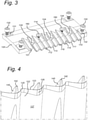
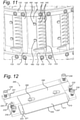
- FIG. 1-11 A first embodiment of a knife assembly according to the invention will be described with reference to Figs. 1-11 .
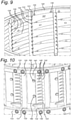
- the knife assembly 100 is for an annular-shaped cutting head, shown in Figs. 9-11 .
- Cutting apparatuses of this type, comprising a cutting head and an impeller have been described a.o.
- the cross-sectional thickness of the clamp 140 along the frontal part 122, or at least the leading edge 123 of the holder 120 can be increased.
- This increased cross-sectional thickness means that there is more material opposite the frontal part 122 or leading edge 123, which can result in a stronger holding force on the knife blade 110.
- the contact surface area between the knife blade 110 and the clamp 140 can also be increased, i.e. the knife blade 110 can be held between larger areas.
- the protruding parts of the knife clamp 140 past the holder 120 can also provide more precise locating support to the knife blade very near the cutting edge. Tests have shown that this precise support can reduce or eliminate the flex of the knife blade 110 and the risk of a resulting gap underneath the knife blade, i.e.
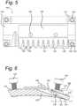
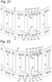
- the knife assembly 200 is likewise for an annular-shaped cutting head.
- the knife assembly 200 is provided for mounting a flat or planar knife blade 210.
- the knife assembly 200 comprises a holder 220, which is in this embodiment likewise a wall segment for the cutting head.
- the holder 220 has a bearing surface 221 which is configured for supporting the knife blade 210.
- the holder 220 and/or the clamp 240 are provided for defining the position of the knife blade 210 on the holder. In the embodiment shown, this is provided by means of positioning pins 224 (see Fig. 14 ) on the holder, the knife blade 210 having corresponding holes.
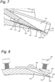
- the included angle between the top surface 247 of the clamp and the top surface 212 of the knife blade 210 is in the range of 6 to 12°. It has been found that by extending the clamp, such that its leading edge or frontal tip is moved forward on the knife assembly, the included angle between the top surface of the clamp and the knife blade can be reduced. This can in turn lead to a reduced "rake-off angle".
- knife assemblies according to the invention may be the same as or similar to the knife assembly 100, except for being configured for mounting to a cutting wheel instead of a cutting head.
- knife assemblies according to the invention may be similar to the knife assembly 100, i.e. for clamping corrugated knife blades, with the difference that clamp 140 has fingers 145 of different lengths.
- a clamp according to such an embodiment may for example have a first set of fingers of which the frontal tip is located in front of the front edge 123 of the holder 120 (in the same way as shown in Figs. 1-11 ) and a second set of fingers which are shorter and of which the frontal tip is located behind or rearward from the front edge 123 of the holder.
- the first set may for example alternate with the second set.
- knife assemblies according to the invention may be similar to the knife assembly 200, i.e. for clamping flat or planar knife blades, with the difference that the top surface 247 of the clamp 140 is not a planar surface like in the embodiment shown in Figs. 12-22 (with the front edge 242 being a straight line), but a non-planar surface.
- a clamp according to such an embodiment may for example have a convex or concave top surface, with the front edge then being correspondingly curved, with for example only part of the curved front edge being located in front of the edge 223 of the holder (e.g.
- the clamp may have at least one clamping part of which a frontal tip, in clamped state, clamps onto a top side of the knife blade at a location which is spaced the second distance D2 from the cutting edge 111, 211, the second distance D2 being smaller than the first distance D1 between the front edge 123, 223 of the holder and the cutting edge 111, 211.
Landscapes
- Life Sciences & Earth Sciences (AREA)
- Forests & Forestry (AREA)
- Engineering & Computer Science (AREA)
- Mechanical Engineering (AREA)
- Details Of Cutting Devices (AREA)
- Knives (AREA)
Claims (16)
- Eine Messeranordnung (100, 200, 300), umfassend:eine Messerklinge (110, 210, 310), bei der eine Vorderkante (123, 223) eine Schneidkante (111, 211, 311) ist;einen Halter (120, 220, 320), der zum Halten der Messerklinge (110, 210, 310) konfiguriert ist;eine Klemme (140, 240, 340), die zum Festklemmen der Messerklinge (110, 210, 310) auf dem Halter angeordnet ist (120, 220, 320); undeinen Befestigungsmechanismus (160, 260, 360), der mit der Klemme (140, 240, 340) und dem Halter (120, 220, 320) zusammenwirkt, um die Messerklinge (110, 210, 310) zwischen der Klemme (140, 240, 340) und dem Halter (120, 220, 320) zu sichern und festzuklemmen, wobei die Schneidkante (111, 211, 311) an einer Vorderseite der Messeranordnung (100, 200, 300) hervorsteht;dadurch gekennzeichnet, dass der Halter (120, 220, 320) einen vorderen Teil (122, 222) aufweist, von dem eine vorderste Kontaktstelle im festgeklemmten Zustand mit einer Unterseite der Messerklinge (110, 210, 310) in einem ersten Abstand (D1) von der Schneidkante (111, 211, 311) in Kontakt steht, wobei die Klemme (140, 240, 340) eine Vorderkante aufweist, die im festgeklemmten Zustand an einer Oberseite der Messerklinge (110, 210, 310) in einem zweiten Abstand (D2) von der Schneidkante (111, 211, 311) festklemmt, wobei der zweite Abstand kleiner als der erste Abstand ist, und wobei der Halter (120, 220, 320) und die Klemme (140, 240, 340) komplementär geformte Oberflächen aufweisen, so dass im festgeklemmten Zustand sowohl der Halter (120, 220, 320) als auch die Klemme (140, 240, 340) einen Oberflächenkontakt mit der Messerklinge (110, 210, 310) aufweisen.
- Die Messeranordnung (100, 200, 300) nach Anspruch 1, wobei im festgeklemmten Zustand die Vorderkante der Klemme die Oberseite der Messerklinge (110, 210, 310) entlang einer ersten Klemmlinie (143, 243) berührt, wobei sich die erste Klemmlinie in dem zweiten Abstand (D2) von der Schneidkante (111, 211, 311) befindet, und der vordere Teil (122, 222) des Halters (120, 220, 320) die Unterseite der Messerklinge (110, 210, 310) entlang mindestens einer vorderen Kontaktlinie berührt, wobei die vordere Kontaktlinie in dem ersten Abstand (D1) von der Schneidkante (111, 211, 311) angeordnet ist.
- Die Messeranordnung (100, 200, 300) nach Anspruch 2, wobei die Klemme (140, 240, 340) vorgesehen ist, um im festgeklemmten Zustand die Messerklinge (110, 210, 310) mittels eines zweiten Klemmabschnitts entlang mindestens einer zweiten Klemmlinie festzuklemmen, wobei sich die zweite Klemmlinie in einem vorbestimmten Abstand (D3) hinter der ersten Klemmlinie (143, 243) befindet.
- Die Messeranordnung (100, 200, 300) nach Anspruch 3, wobei sich die zweite Klemmlinie hinter der vorderen Kontaktlinie befindet, entlang welcher der vordere Teil (122, 222) des Halters (120, 220, 320) die Unterseite der Messerklinge (110, 210, 310) berührt.
- Die Messeranordnung (100, 200, 300) nach einem der vorhergehenden Ansprüche, wobei
die Länge der Klemmfläche, gemessen in rückwärtiger Richtung von der Vorderkante der Klemme (140, 240, 340), mindestens 2,0 mm beträgt und vorzugsweise im Bereich von 8,0 bis 14,0 mm, besonders bevorzugt 11,0 bis 13,0 mm liegt. - Die Messeranordnung (100, 200, 300) nach einem der vorhergehenden Ansprüche, wobei die Messerklinge (110, 210, 310) gewellt ist und Spitzen (115, 125) und Täler (116, 126) aufweist.
- Die Messeranordnung (100, 200, 300) nach Anspruch 6, wobei die Klemme (140, 240, 340) Finger umfasst, die in die Täler der Messerklinge (110, 210, 310) eingreifen.
- Die Messeranordnung (100, 200, 300) nach Anspruch 6 oder 7, wobei der Halter (120, 220, 320) eine Auflagefläche mit Spitzen (115, 125) und Tälern (116, 126) umfasst, die den Spitzen und Tälern der Messerklinge (110, 210, 310) entsprechen.
- Die Messeranordnung (100, 200, 300) nach einem der Ansprüche 1-5, wobei die Messerklinge (110, 210, 310) eine flache Messerklinge ist.
- Die Messeranordnung (100, 200, 300) nach Anspruch 9, wobei der Halter (120, 220, 320) eine gekrümmte Auflagefläche aufweist und die Klemme (140, 240, 340) eine komplementäre gekrümmte Klemmfläche aufweist.
- Die Messeranordnung (100, 200, 300) nach einem der vorhergehenden Ansprüche, wobei die Klemme (140, 240, 340) eine obere Fläche aufweist, die sich von der Vorderkante nach hinten erstreckt und im geklemmten Zustand einen Winkel von 6 bis 12° Grad mit der Messerklinge (110, 210, 310) bildet.
- Die Messeranordnung (100, 200, 300) nach einem der vorhergehenden Ansprüche, wobei der erste Abstand (D1) 3,0 bis 8,0 mm beträgt, vorzugsweise 3,0 bis 5,0 mm, und wobei der zweite Abstand (D2) 0,1 bis 7,5 mm beträgt, vorzugsweise 0,1 bis 4,5 mm.
- Ein ringförmiger Schneidkopf, umfassend mindestens eine Randstruktur (133, 233) und eine Vielzahl von Messeranordnungen nach einem der Ansprüche 1-12, die auf der mindestens einen Randstruktur montiert sind.
- Eine Zentrifugalschneidvorrichtung, umfassend einen Schneidkopf nach Anspruch 13.
- Ein Schneidrad, umfassend eine Nabe, einen Radkranz und eine Vielzahl von Messeranordnungen nach einem der Ansprüche 1-12, die zwischen der Nabe und dem Radkranz montiert sind.
- Eine Schneidvorrichtung, umfassend ein Schneidrad nach Anspruch 15.
Priority Applications (2)
| Application Number | Priority Date | Filing Date | Title |
|---|---|---|---|
| EP21213448.0A EP3988266A1 (de) | 2018-02-20 | 2019-02-19 | Messeranordnung und damit ausgestattetes schneidsystem |
| PL19705188.1T PL3755510T5 (pl) | 2018-02-20 | 2019-02-19 | Zespół noża i wyposażony w niego układ cięcia |
Applications Claiming Priority (2)
| Application Number | Priority Date | Filing Date | Title |
|---|---|---|---|
| EP18157572.1A EP3527342A1 (de) | 2018-02-20 | 2018-02-20 | Messeranordnung und damit ausgestattetes schneidsystem |
| PCT/EP2019/054105 WO2019162278A1 (en) | 2018-02-20 | 2019-02-19 | Knife assembly and cutting system equipped with same |
Related Child Applications (2)
| Application Number | Title | Priority Date | Filing Date |
|---|---|---|---|
| EP21213448.0A Division-Into EP3988266A1 (de) | 2018-02-20 | 2019-02-19 | Messeranordnung und damit ausgestattetes schneidsystem |
| EP21213448.0A Division EP3988266A1 (de) | 2018-02-20 | 2019-02-19 | Messeranordnung und damit ausgestattetes schneidsystem |
Publications (3)
| Publication Number | Publication Date |
|---|---|
| EP3755510A1 EP3755510A1 (de) | 2020-12-30 |
| EP3755510B1 true EP3755510B1 (de) | 2022-02-09 |
| EP3755510B2 EP3755510B2 (de) | 2025-08-20 |
Family
ID=61249553
Family Applications (3)
| Application Number | Title | Priority Date | Filing Date |
|---|---|---|---|
| EP18157572.1A Withdrawn EP3527342A1 (de) | 2018-02-20 | 2018-02-20 | Messeranordnung und damit ausgestattetes schneidsystem |
| EP19705188.1A Active EP3755510B2 (de) | 2018-02-20 | 2019-02-19 | Messeranordnung und damit ausgestattetes schneidsystem |
| EP21213448.0A Pending EP3988266A1 (de) | 2018-02-20 | 2019-02-19 | Messeranordnung und damit ausgestattetes schneidsystem |
Family Applications Before (1)
| Application Number | Title | Priority Date | Filing Date |
|---|---|---|---|
| EP18157572.1A Withdrawn EP3527342A1 (de) | 2018-02-20 | 2018-02-20 | Messeranordnung und damit ausgestattetes schneidsystem |
Family Applications After (1)
| Application Number | Title | Priority Date | Filing Date |
|---|---|---|---|
| EP21213448.0A Pending EP3988266A1 (de) | 2018-02-20 | 2019-02-19 | Messeranordnung und damit ausgestattetes schneidsystem |
Country Status (5)
| Country | Link |
|---|---|
| US (2) | US11772293B2 (de) |
| EP (3) | EP3527342A1 (de) |
| ES (1) | ES2911810T5 (de) |
| PL (1) | PL3755510T5 (de) |
| WO (1) | WO2019162278A1 (de) |
Families Citing this family (7)
| Publication number | Priority date | Publication date | Assignee | Title |
|---|---|---|---|---|
| US11590671B2 (en) * | 2020-07-09 | 2023-02-28 | Urschel Laboratories, Inc. | Knife holders, cutting heads and slicing machines equipped therewith, and processes of manufacture |
| US12220831B2 (en) * | 2021-04-20 | 2025-02-11 | Urschel Laboratories, Inc. | Knife assemblies of slicing machines, methods of clamping and releasing knives therefrom, and slicing machines equipped therewith |
| AU2022421990B2 (en) * | 2021-12-23 | 2025-09-04 | Urschel Laboratories, Inc. | Clamping assemblies to secure knives to slicing machines and slicing machines equipped therewith |
| CN114800639B (zh) * | 2022-04-06 | 2023-11-28 | 安徽德昌药业股份有限公司 | 一种白芷片用切制装置 |
| TWI858746B (zh) * | 2023-05-31 | 2024-10-11 | 台乙機械有限公司 | 用於波紋刀片的刀具組件及配備所述刀具組件的環形切割裝置 |
| CN117245700A (zh) * | 2023-09-22 | 2023-12-19 | 苏州德赛斯厨房设备有限公司 | 一种果蔬滚刀块成型用切割组件 |
| JP7788745B2 (ja) * | 2024-02-29 | 2025-12-19 | 旭マシナリー株式会社 | ロータリーカッター装置 |
Citations (11)
| Publication number | Priority date | Publication date | Assignee | Title |
|---|---|---|---|---|
| US4937084A (en) | 1983-08-22 | 1990-06-26 | Lamb-Weston, Inc. | Waffle-cut potato product |
| US5211097A (en) | 1990-01-16 | 1993-05-18 | Giorgio Grasselli | Blade-holding device |
| US5819628A (en) | 1993-11-12 | 1998-10-13 | Recot, Inc. | Replaceable blade cartridge for a centrifugal type food slicer |
| US20030145698A1 (en) | 2002-02-04 | 2003-08-07 | Bucks Brent L. | Method and apparatus for delivering product to a cutting device |
| US20050150345A1 (en) | 2004-01-13 | 2005-07-14 | Bucks Brent L. | Knife and cutting wheel for a food product slicing apparatus |
| EP1584429A1 (de) | 2004-04-09 | 2005-10-12 | Fam | Schneidrad zum Schneiden von Nahrungsmitteln |
| US20070240550A1 (en) | 2006-04-18 | 2007-10-18 | Urschel Laboratories, Inc. | Apparatus for cutting food product |
| US20100206185A1 (en) | 2003-07-02 | 2010-08-19 | Bucks Brent L | Knife and cutting wheel for a food product slicing apparatus |
| US20140007751A1 (en) | 2011-12-27 | 2014-01-09 | Frito-Lay North America Inc. | Apparatuses for cutting food products |
| WO2015075179A1 (en) | 2013-11-21 | 2015-05-28 | Fam | Knife assembly for flat knife blade and cutting system equipped with same |
| US20170087735A1 (en) | 2015-09-24 | 2017-03-30 | Urschel Laboratories, Inc. | Slicing machines, knife assemblies, and methods for slicing products |
Family Cites Families (36)
| Publication number | Priority date | Publication date | Assignee | Title |
|---|---|---|---|---|
| SE405081B (sv) * | 1974-02-07 | 1978-11-20 | Sandvik Ab | Kniv for tyngre bearbetning |
| US4511586A (en) * | 1983-08-03 | 1985-04-16 | Frito-Lay, Inc. | Potato product with opposite phase-shifted corrugations of the same frequency and amplitude |
| US4523503A (en) * | 1983-08-22 | 1985-06-18 | Lamb-Weston, Inc. | Apparatus for making waffle-cut potato |
| JPS60153796U (ja) * | 1984-03-23 | 1985-10-14 | カルビ−株式会社 | 食品材料用カツタ |
| US4794961A (en) * | 1986-05-02 | 1989-01-03 | Tomo Bonac | Veneer knife |
| US4945794A (en) * | 1988-08-08 | 1990-08-07 | Frito-Lay, Inc. | Method and apparatus for feeding produce items to centrifugal slicers |
| US5095875A (en) * | 1989-06-21 | 1992-03-17 | Carl Morris | Knife for producing waffle and lattice cuts |
| US5494478A (en) * | 1995-02-13 | 1996-02-27 | Long; John W. | Toolless quick change blade holder apparatus |
| DE19921597C1 (de) * | 1999-05-07 | 2000-07-27 | Maier Zerkleinerungsanlage Gmb | Messerring-Zerspaner zum Zerspanen von Hackschnitzeln |
| SE519136C2 (sv) * | 2000-07-17 | 2003-01-21 | Iggesund Tools Ab | Huggkniv samt hållaranordning till densamma |
| US6299523B1 (en) * | 2001-02-06 | 2001-10-09 | Townsend Engineering Company | Means for remotely ejecting the blade of a meat skinning machine |
| US6458025B1 (en) * | 2001-05-15 | 2002-10-01 | Townsend Engineering Company | Removable skinning blade assembly for meat skinning machine |
| US6589108B2 (en) * | 2001-06-08 | 2003-07-08 | Townsend Engineering Company | Tapered blade and holder for a meat skinning machine |
| US6662837B2 (en) * | 2001-07-16 | 2003-12-16 | Paul M. Smith | Replaceable blades for wood chippers |
| US6591878B2 (en) * | 2001-07-18 | 2003-07-15 | Key Knife, Inc. | Method and apparatus for clamping a knife |
| CA2686670C (en) * | 2002-01-17 | 2012-09-25 | Iggesund Tools Ab | Multi-application wood working knife and clamping assembly |
| US7836923B2 (en) * | 2002-10-25 | 2010-11-23 | Key Knife, Inc. | Ring slicer with easily removable knife and knife assembly |
| EP1626844B1 (de) * | 2003-05-29 | 2013-05-08 | Urschel Laboratories, Inc. | Schneidkopf zum schneiden von nahrungsmittelprodukten |
| US7069969B2 (en) * | 2003-09-25 | 2006-07-04 | Key Knife, Inc. | Wood cutting knife assembly providing improved knife stability |
| US8033308B2 (en) * | 2007-01-08 | 2011-10-11 | Key Knife, Inc. | Double-sided wear insert for a chipper |
| US7891388B2 (en) * | 2007-06-29 | 2011-02-22 | Key Knife, Inc. | Knife and knife assembly for a planer side head |
| BE1019977A3 (nl) | 2011-04-11 | 2013-03-05 | Fam | Inrichting en werkwijze voor het snijden van producten. |
| BE1020687A3 (nl) | 2011-09-28 | 2014-03-04 | Fam | Impeller voor centrifugaal voedselsnijapparaat, en hiermee uitgerust centrifugaal voedselsnijapparaat. |
| BE1020824A5 (nl) | 2011-09-28 | 2014-05-06 | Fam | Snijkopsamenstelsel voor centrifugaal snijapparaat, en hiermee uitgerust centrifugaal snijapparaat. |
| US9462818B2 (en) * | 2012-01-18 | 2016-10-11 | Frito-Lay North America, Inc. | High amplitude corrugated food product |
| AU2013251730B2 (en) * | 2012-04-23 | 2016-08-04 | Urschel Laboratories, Inc. | Methods and equipment for cutting food products |
| US9840015B2 (en) * | 2012-04-23 | 2017-12-12 | Urschel Laboratories, Inc. | Knife assembly with tab blade |
| US8714068B2 (en) * | 2012-09-28 | 2014-05-06 | Frito-Lay North America, Inc. | Tailored slicing |
| US9592618B2 (en) * | 2013-03-13 | 2017-03-14 | Ballreich Bros., Inc. | Wavy shaped potato sticks |
| MX377147B (es) | 2013-12-10 | 2025-03-07 | Urschel Laboratories Inc | Ensamble de cuchilla con navaja de lengüeta. |
| PL2918384T3 (pl) | 2014-03-10 | 2021-03-08 | Fam | Zespół głowicy tnącej do urządzenia do cięcia odśrodkowego i urządzenie odśrodkowe wyposażone w niego |
| US10611042B2 (en) * | 2015-04-06 | 2020-04-07 | Urschel Laboratories, Inc. | Cutting wheels and knife assemblies thereof for cutting products |
| PL3461605T3 (pl) * | 2017-10-02 | 2023-12-11 | Fam | Głowica tnąca do odśrodkowego urządzenia tnącego i odśrodkowe urządzenie tnące w nią wyposażone |
| CA3070867C (en) * | 2018-01-05 | 2023-04-25 | Urschel Laboratories, Inc. | Knife assemblies for slicing machines and machines equipped therewith |
| WO2020142582A1 (en) * | 2019-01-02 | 2020-07-09 | Urschel Laboratories, Inc. | Cutting heads, cutting machines equipped therewith, and methods of operation |
| WO2020146304A1 (en) * | 2019-01-10 | 2020-07-16 | Urschel Laboratories, Inc. | Apparatuses for cutting food products and methods for operating the same |
-
2018
- 2018-02-20 EP EP18157572.1A patent/EP3527342A1/de not_active Withdrawn
-
2019
- 2019-02-19 US US16/970,640 patent/US11772293B2/en active Active
- 2019-02-19 WO PCT/EP2019/054105 patent/WO2019162278A1/en not_active Ceased
- 2019-02-19 ES ES19705188T patent/ES2911810T5/es active Active
- 2019-02-19 EP EP19705188.1A patent/EP3755510B2/de active Active
- 2019-02-19 EP EP21213448.0A patent/EP3988266A1/de active Pending
- 2019-02-19 PL PL19705188.1T patent/PL3755510T5/pl unknown
-
2023
- 2023-08-17 US US18/451,139 patent/US12409576B2/en active Active
Patent Citations (11)
| Publication number | Priority date | Publication date | Assignee | Title |
|---|---|---|---|---|
| US4937084A (en) | 1983-08-22 | 1990-06-26 | Lamb-Weston, Inc. | Waffle-cut potato product |
| US5211097A (en) | 1990-01-16 | 1993-05-18 | Giorgio Grasselli | Blade-holding device |
| US5819628A (en) | 1993-11-12 | 1998-10-13 | Recot, Inc. | Replaceable blade cartridge for a centrifugal type food slicer |
| US20030145698A1 (en) | 2002-02-04 | 2003-08-07 | Bucks Brent L. | Method and apparatus for delivering product to a cutting device |
| US20100206185A1 (en) | 2003-07-02 | 2010-08-19 | Bucks Brent L | Knife and cutting wheel for a food product slicing apparatus |
| US20050150345A1 (en) | 2004-01-13 | 2005-07-14 | Bucks Brent L. | Knife and cutting wheel for a food product slicing apparatus |
| EP1584429A1 (de) | 2004-04-09 | 2005-10-12 | Fam | Schneidrad zum Schneiden von Nahrungsmitteln |
| US20070240550A1 (en) | 2006-04-18 | 2007-10-18 | Urschel Laboratories, Inc. | Apparatus for cutting food product |
| US20140007751A1 (en) | 2011-12-27 | 2014-01-09 | Frito-Lay North America Inc. | Apparatuses for cutting food products |
| WO2015075179A1 (en) | 2013-11-21 | 2015-05-28 | Fam | Knife assembly for flat knife blade and cutting system equipped with same |
| US20170087735A1 (en) | 2015-09-24 | 2017-03-30 | Urschel Laboratories, Inc. | Slicing machines, knife assemblies, and methods for slicing products |
Non-Patent Citations (1)
| Title |
|---|
| D12 - Letter of the representatives of the Opponent dated 16 May 2024, which constitutes theStatement of Grounds of Appeal in the opposition-appeal proceedings relating to Europeanpatent No. 3 352 956 |
Also Published As
| Publication number | Publication date |
|---|---|
| EP3527342A1 (de) | 2019-08-21 |
| WO2019162278A1 (en) | 2019-08-29 |
| EP3755510A1 (de) | 2020-12-30 |
| ES2911810T3 (es) | 2022-05-20 |
| US11772293B2 (en) | 2023-10-03 |
| EP3755510B2 (de) | 2025-08-20 |
| PL3755510T3 (pl) | 2022-05-30 |
| US12409576B2 (en) | 2025-09-09 |
| US20230390956A1 (en) | 2023-12-07 |
| EP3988266A1 (de) | 2022-04-27 |
| PL3755510T5 (pl) | 2025-12-15 |
| ES2911810T5 (en) | 2026-01-14 |
| US20210086387A1 (en) | 2021-03-25 |
Similar Documents
| Publication | Publication Date | Title |
|---|---|---|
| US12409576B2 (en) | Knife assembly and cutting system equipped with same | |
| EP3718717B1 (de) | Schneidkopfanordnung für eine zentrifugalschneidvorrichtung und zentrifugalvorrichtung mit der anordnung | |
| EP3071379B1 (de) | Messeranordnung für eine schneidvorrichtung und vorrichtung damit | |
| US20220152859A1 (en) | Cutting head for a centrifugal cutting apparatus and centrifugal cutting apparatus equipped with same | |
| AU2005206679B2 (en) | Knife and cutting wheel for a food product slicing apparatus | |
| WO2004069502A9 (en) | Chipper knife |
Legal Events
| Date | Code | Title | Description |
|---|---|---|---|
| STAA | Information on the status of an ep patent application or granted ep patent |
Free format text: STATUS: UNKNOWN |
|
| STAA | Information on the status of an ep patent application or granted ep patent |
Free format text: STATUS: THE INTERNATIONAL PUBLICATION HAS BEEN MADE |
|
| PUAI | Public reference made under article 153(3) epc to a published international application that has entered the european phase |
Free format text: ORIGINAL CODE: 0009012 |
|
| STAA | Information on the status of an ep patent application or granted ep patent |
Free format text: STATUS: REQUEST FOR EXAMINATION WAS MADE |
|
| 17P | Request for examination filed |
Effective date: 20200917 |
|
| AK | Designated contracting states |
Kind code of ref document: A1 Designated state(s): AL AT BE BG CH CY CZ DE DK EE ES FI FR GB GR HR HU IE IS IT LI LT LU LV MC MK MT NL NO PL PT RO RS SE SI SK SM TR |
|
| AX | Request for extension of the european patent |
Extension state: BA ME |
|
| DAV | Request for validation of the european patent (deleted) | ||
| DAX | Request for extension of the european patent (deleted) | ||
| GRAP | Despatch of communication of intention to grant a patent |
Free format text: ORIGINAL CODE: EPIDOSNIGR1 |
|
| STAA | Information on the status of an ep patent application or granted ep patent |
Free format text: STATUS: GRANT OF PATENT IS INTENDED |
|
| INTG | Intention to grant announced |
Effective date: 20211019 |
|
| GRAS | Grant fee paid |
Free format text: ORIGINAL CODE: EPIDOSNIGR3 |
|
| GRAA | (expected) grant |
Free format text: ORIGINAL CODE: 0009210 |
|
| STAA | Information on the status of an ep patent application or granted ep patent |
Free format text: STATUS: THE PATENT HAS BEEN GRANTED |
|
| AK | Designated contracting states |
Kind code of ref document: B1 Designated state(s): AL AT BE BG CH CY CZ DE DK EE ES FI FR GB GR HR HU IE IS IT LI LT LU LV MC MK MT NL NO PL PT RO RS SE SI SK SM TR |
|
| REG | Reference to a national code |
Ref country code: GB Ref legal event code: FG4D |
|
| REG | Reference to a national code |
Ref country code: CH Ref legal event code: EP Ref country code: AT Ref legal event code: REF Ref document number: 1467227 Country of ref document: AT Kind code of ref document: T Effective date: 20220215 |
|
| REG | Reference to a national code |
Ref country code: IE Ref legal event code: FG4D |
|
| REG | Reference to a national code |
Ref country code: DE Ref legal event code: R096 Ref document number: 602019011490 Country of ref document: DE |
|
| REG | Reference to a national code |
Ref country code: NL Ref legal event code: FP |
|
| REG | Reference to a national code |
Ref country code: ES Ref legal event code: FG2A Ref document number: 2911810 Country of ref document: ES Kind code of ref document: T3 Effective date: 20220520 |
|
| REG | Reference to a national code |
Ref country code: LT Ref legal event code: MG9D |
|
| REG | Reference to a national code |
Ref country code: AT Ref legal event code: MK05 Ref document number: 1467227 Country of ref document: AT Kind code of ref document: T Effective date: 20220209 |
|
| PG25 | Lapsed in a contracting state [announced via postgrant information from national office to epo] |
Ref country code: SE Free format text: LAPSE BECAUSE OF FAILURE TO SUBMIT A TRANSLATION OF THE DESCRIPTION OR TO PAY THE FEE WITHIN THE PRESCRIBED TIME-LIMIT Effective date: 20220209 Ref country code: RS Free format text: LAPSE BECAUSE OF FAILURE TO SUBMIT A TRANSLATION OF THE DESCRIPTION OR TO PAY THE FEE WITHIN THE PRESCRIBED TIME-LIMIT Effective date: 20220209 Ref country code: PT Free format text: LAPSE BECAUSE OF FAILURE TO SUBMIT A TRANSLATION OF THE DESCRIPTION OR TO PAY THE FEE WITHIN THE PRESCRIBED TIME-LIMIT Effective date: 20220609 Ref country code: NO Free format text: LAPSE BECAUSE OF FAILURE TO SUBMIT A TRANSLATION OF THE DESCRIPTION OR TO PAY THE FEE WITHIN THE PRESCRIBED TIME-LIMIT Effective date: 20220509 Ref country code: LT Free format text: LAPSE BECAUSE OF FAILURE TO SUBMIT A TRANSLATION OF THE DESCRIPTION OR TO PAY THE FEE WITHIN THE PRESCRIBED TIME-LIMIT Effective date: 20220209 Ref country code: HR Free format text: LAPSE BECAUSE OF FAILURE TO SUBMIT A TRANSLATION OF THE DESCRIPTION OR TO PAY THE FEE WITHIN THE PRESCRIBED TIME-LIMIT Effective date: 20220209 Ref country code: BG Free format text: LAPSE BECAUSE OF FAILURE TO SUBMIT A TRANSLATION OF THE DESCRIPTION OR TO PAY THE FEE WITHIN THE PRESCRIBED TIME-LIMIT Effective date: 20220509 |
|
| PG25 | Lapsed in a contracting state [announced via postgrant information from national office to epo] |
Ref country code: LV Free format text: LAPSE BECAUSE OF FAILURE TO SUBMIT A TRANSLATION OF THE DESCRIPTION OR TO PAY THE FEE WITHIN THE PRESCRIBED TIME-LIMIT Effective date: 20220209 Ref country code: GR Free format text: LAPSE BECAUSE OF FAILURE TO SUBMIT A TRANSLATION OF THE DESCRIPTION OR TO PAY THE FEE WITHIN THE PRESCRIBED TIME-LIMIT Effective date: 20220510 Ref country code: FI Free format text: LAPSE BECAUSE OF FAILURE TO SUBMIT A TRANSLATION OF THE DESCRIPTION OR TO PAY THE FEE WITHIN THE PRESCRIBED TIME-LIMIT Effective date: 20220209 Ref country code: AT Free format text: LAPSE BECAUSE OF FAILURE TO SUBMIT A TRANSLATION OF THE DESCRIPTION OR TO PAY THE FEE WITHIN THE PRESCRIBED TIME-LIMIT Effective date: 20220209 |
|
| PG25 | Lapsed in a contracting state [announced via postgrant information from national office to epo] |
Ref country code: IS Free format text: LAPSE BECAUSE OF FAILURE TO SUBMIT A TRANSLATION OF THE DESCRIPTION OR TO PAY THE FEE WITHIN THE PRESCRIBED TIME-LIMIT Effective date: 20220609 |
|
| REG | Reference to a national code |
Ref country code: CH Ref legal event code: PL |
|
| PG25 | Lapsed in a contracting state [announced via postgrant information from national office to epo] |
Ref country code: SM Free format text: LAPSE BECAUSE OF FAILURE TO SUBMIT A TRANSLATION OF THE DESCRIPTION OR TO PAY THE FEE WITHIN THE PRESCRIBED TIME-LIMIT Effective date: 20220209 Ref country code: SK Free format text: LAPSE BECAUSE OF FAILURE TO SUBMIT A TRANSLATION OF THE DESCRIPTION OR TO PAY THE FEE WITHIN THE PRESCRIBED TIME-LIMIT Effective date: 20220209 Ref country code: RO Free format text: LAPSE BECAUSE OF FAILURE TO SUBMIT A TRANSLATION OF THE DESCRIPTION OR TO PAY THE FEE WITHIN THE PRESCRIBED TIME-LIMIT Effective date: 20220209 Ref country code: LU Free format text: LAPSE BECAUSE OF NON-PAYMENT OF DUE FEES Effective date: 20220219 Ref country code: EE Free format text: LAPSE BECAUSE OF FAILURE TO SUBMIT A TRANSLATION OF THE DESCRIPTION OR TO PAY THE FEE WITHIN THE PRESCRIBED TIME-LIMIT Effective date: 20220209 Ref country code: DK Free format text: LAPSE BECAUSE OF FAILURE TO SUBMIT A TRANSLATION OF THE DESCRIPTION OR TO PAY THE FEE WITHIN THE PRESCRIBED TIME-LIMIT Effective date: 20220209 Ref country code: CZ Free format text: LAPSE BECAUSE OF FAILURE TO SUBMIT A TRANSLATION OF THE DESCRIPTION OR TO PAY THE FEE WITHIN THE PRESCRIBED TIME-LIMIT Effective date: 20220209 |
|
| REG | Reference to a national code |
Ref country code: DE Ref legal event code: R026 Ref document number: 602019011490 Country of ref document: DE |
|
| PLBI | Opposition filed |
Free format text: ORIGINAL CODE: 0009260 |
|
| PLAX | Notice of opposition and request to file observation + time limit sent |
Free format text: ORIGINAL CODE: EPIDOSNOBS2 |
|
| PG25 | Lapsed in a contracting state [announced via postgrant information from national office to epo] |
Ref country code: MC Free format text: LAPSE BECAUSE OF FAILURE TO SUBMIT A TRANSLATION OF THE DESCRIPTION OR TO PAY THE FEE WITHIN THE PRESCRIBED TIME-LIMIT Effective date: 20220209 Ref country code: AL Free format text: LAPSE BECAUSE OF FAILURE TO SUBMIT A TRANSLATION OF THE DESCRIPTION OR TO PAY THE FEE WITHIN THE PRESCRIBED TIME-LIMIT Effective date: 20220209 |
|
| 26 | Opposition filed |
Opponent name: URSCHEL LABORATORIES, INC. Effective date: 20221109 |
|
| PG25 | Lapsed in a contracting state [announced via postgrant information from national office to epo] |
Ref country code: LI Free format text: LAPSE BECAUSE OF NON-PAYMENT OF DUE FEES Effective date: 20220228 Ref country code: IE Free format text: LAPSE BECAUSE OF NON-PAYMENT OF DUE FEES Effective date: 20220219 Ref country code: CH Free format text: LAPSE BECAUSE OF NON-PAYMENT OF DUE FEES Effective date: 20220228 |
|
| PG25 | Lapsed in a contracting state [announced via postgrant information from national office to epo] |
Ref country code: SI Free format text: LAPSE BECAUSE OF FAILURE TO SUBMIT A TRANSLATION OF THE DESCRIPTION OR TO PAY THE FEE WITHIN THE PRESCRIBED TIME-LIMIT Effective date: 20220209 |
|
| PLBB | Reply of patent proprietor to notice(s) of opposition received |
Free format text: ORIGINAL CODE: EPIDOSNOBS3 |
|
| PG25 | Lapsed in a contracting state [announced via postgrant information from national office to epo] |
Ref country code: MK Free format text: LAPSE BECAUSE OF FAILURE TO SUBMIT A TRANSLATION OF THE DESCRIPTION OR TO PAY THE FEE WITHIN THE PRESCRIBED TIME-LIMIT Effective date: 20220209 Ref country code: CY Free format text: LAPSE BECAUSE OF FAILURE TO SUBMIT A TRANSLATION OF THE DESCRIPTION OR TO PAY THE FEE WITHIN THE PRESCRIBED TIME-LIMIT Effective date: 20220209 |
|
| PG25 | Lapsed in a contracting state [announced via postgrant information from national office to epo] |
Ref country code: HU Free format text: LAPSE BECAUSE OF FAILURE TO SUBMIT A TRANSLATION OF THE DESCRIPTION OR TO PAY THE FEE WITHIN THE PRESCRIBED TIME-LIMIT; INVALID AB INITIO Effective date: 20190219 |
|
| PG25 | Lapsed in a contracting state [announced via postgrant information from national office to epo] |
Ref country code: MT Free format text: LAPSE BECAUSE OF FAILURE TO SUBMIT A TRANSLATION OF THE DESCRIPTION OR TO PAY THE FEE WITHIN THE PRESCRIBED TIME-LIMIT Effective date: 20220209 |
|
| PGFP | Annual fee paid to national office [announced via postgrant information from national office to epo] |
Ref country code: NL Payment date: 20250227 Year of fee payment: 7 |
|
| PGFP | Annual fee paid to national office [announced via postgrant information from national office to epo] |
Ref country code: DE Payment date: 20250227 Year of fee payment: 7 |
|
| PGFP | Annual fee paid to national office [announced via postgrant information from national office to epo] |
Ref country code: ES Payment date: 20250303 Year of fee payment: 7 |
|
| PGFP | Annual fee paid to national office [announced via postgrant information from national office to epo] |
Ref country code: BE Payment date: 20250227 Year of fee payment: 7 |
|
| PGFP | Annual fee paid to national office [announced via postgrant information from national office to epo] |
Ref country code: PL Payment date: 20250203 Year of fee payment: 7 Ref country code: FR Payment date: 20250225 Year of fee payment: 7 |
|
| PGFP | Annual fee paid to national office [announced via postgrant information from national office to epo] |
Ref country code: IT Payment date: 20250220 Year of fee payment: 7 Ref country code: GB Payment date: 20250227 Year of fee payment: 7 |
|
| PUAH | Patent maintained in amended form |
Free format text: ORIGINAL CODE: 0009272 |
|
| STAA | Information on the status of an ep patent application or granted ep patent |
Free format text: STATUS: PATENT MAINTAINED AS AMENDED |
|
| 27A | Patent maintained in amended form |
Effective date: 20250820 |
|
| AK | Designated contracting states |
Kind code of ref document: B2 Designated state(s): AL AT BE BG CH CY CZ DE DK EE ES FI FR GB GR HR HU IE IS IT LI LT LU LV MC MK MT NL NO PL PT RO RS SE SI SK SM TR |
|
| REG | Reference to a national code |
Ref country code: DE Ref legal event code: R102 Ref document number: 602019011490 Country of ref document: DE |
|
| REG | Reference to a national code |
Ref country code: NL Ref legal event code: FP |
|
| PG25 | Lapsed in a contracting state [announced via postgrant information from national office to epo] |
Ref country code: TR Free format text: LAPSE BECAUSE OF FAILURE TO SUBMIT A TRANSLATION OF THE DESCRIPTION OR TO PAY THE FEE WITHIN THE PRESCRIBED TIME-LIMIT Effective date: 20220209 |
|
| REG | Reference to a national code |
Ref country code: ES Ref legal event code: DC2A Ref document number: 2911810 Country of ref document: ES Kind code of ref document: T5 Effective date: 20260114 |