EP3755202B1 - Verfahren zum vergleich optischer linsen, zugehöriges steuermodul und system - Google Patents
Verfahren zum vergleich optischer linsen, zugehöriges steuermodul und system Download PDFInfo
- Publication number
- EP3755202B1 EP3755202B1 EP19706277.1A EP19706277A EP3755202B1 EP 3755202 B1 EP3755202 B1 EP 3755202B1 EP 19706277 A EP19706277 A EP 19706277A EP 3755202 B1 EP3755202 B1 EP 3755202B1
- Authority
- EP
- European Patent Office
- Prior art keywords
- selection
- optical lens
- proposal
- control module
- symbol
- Prior art date
- Legal status (The legal status is an assumption and is not a legal conclusion. Google has not performed a legal analysis and makes no representation as to the accuracy of the status listed.)
- Active
Links
Images


Classifications
-
- G—PHYSICS
- G02—OPTICS
- G02B—OPTICAL ELEMENTS, SYSTEMS OR APPARATUS
- G02B13/00—Optical objectives specially designed for the purposes specified below
- G02B13/18—Optical objectives specially designed for the purposes specified below with lenses having one or more non-spherical faces, e.g. for reducing geometrical aberration
-
- A—HUMAN NECESSITIES
- A61—MEDICAL OR VETERINARY SCIENCE; HYGIENE
- A61B—DIAGNOSIS; SURGERY; IDENTIFICATION
- A61B3/00—Apparatus for testing the eyes; Instruments for examining the eyes
- A61B3/02—Subjective types, i.e. testing apparatus requiring the active assistance of the patient
- A61B3/028—Subjective types, i.e. testing apparatus requiring the active assistance of the patient for testing visual acuity; for determination of refraction, e.g. phoropters
- A61B3/04—Trial frames; Sets of lenses for use therewith
-
- A—HUMAN NECESSITIES
- A61—MEDICAL OR VETERINARY SCIENCE; HYGIENE
- A61B—DIAGNOSIS; SURGERY; IDENTIFICATION
- A61B3/00—Apparatus for testing the eyes; Instruments for examining the eyes
- A61B3/0016—Operational features thereof
- A61B3/0033—Operational features thereof characterised by user input arrangements
-
- A—HUMAN NECESSITIES
- A61—MEDICAL OR VETERINARY SCIENCE; HYGIENE
- A61B—DIAGNOSIS; SURGERY; IDENTIFICATION
- A61B3/00—Apparatus for testing the eyes; Instruments for examining the eyes
- A61B3/0016—Operational features thereof
- A61B3/0041—Operational features thereof characterised by display arrangements
-
- A—HUMAN NECESSITIES
- A61—MEDICAL OR VETERINARY SCIENCE; HYGIENE
- A61B—DIAGNOSIS; SURGERY; IDENTIFICATION
- A61B3/00—Apparatus for testing the eyes; Instruments for examining the eyes
- A61B3/10—Objective types, i.e. instruments for examining the eyes independent of the patients' perceptions or reactions
- A61B3/103—Objective types, i.e. instruments for examining the eyes independent of the patients' perceptions or reactions for determining refraction, e.g. refractometers, skiascopes
-
- G—PHYSICS
- G02—OPTICS
- G02B—OPTICAL ELEMENTS, SYSTEMS OR APPARATUS
- G02B7/00—Mountings, adjusting means, or light-tight connections, for optical elements
- G02B7/02—Mountings, adjusting means, or light-tight connections, for optical elements for lenses
- G02B7/023—Mountings, adjusting means, or light-tight connections, for optical elements for lenses permitting adjustment
-
- G—PHYSICS
- G02—OPTICS
- G02C—SPECTACLES; SUNGLASSES OR GOGGLES INSOFAR AS THEY HAVE THE SAME FEATURES AS SPECTACLES; CONTACT LENSES
- G02C7/00—Optical parts
- G02C7/02—Lenses; Lens systems ; Methods of designing lenses
Definitions
- the field of the invention is that of eye examinations which, carried out on a subject, make it possible to determine whether he needs a correction and which one.
- the invention relates more particularly to a method for comparing optical glasses by means of an automatic refractor head controlled by a control module, for example during an eye examination or during a simple verification of the correction. visual scope.
- the invention also relates to a control module for an automatic refractor head for implementing the method for comparing optical glasses as well as a system comprising the control module and a selection screen for implementing the method. comparison of optical glasses.
- An eye examination of a subject begins with an objective refraction measurement and continues with a subjective refraction measurement.
- Objective refraction measurement is generally performed by an operator using an autorefractometer.
- an autorefractometer As an alternative to the use of an autorefractometer, a manual skiascopy technique is sometimes used. Failing this, the operator can start from the previous correction of the subject examined.
- the operator manually changes the test lenses of the pair of test glasses.
- the operator scrolls different optical glasses in front of the eyes of the examined subject, by means of dials in the case of a manual refractor head or via a control console in the case of an automatic refractor head.
- the document WO 2016/142363 A1 discloses a standard method of comparing optical glasses which are placed in an automatic refractor head. The lenses are selectively adjustable to adjust their spherical power.
- a solution is therefore sought which makes it possible, in particular in the context of an eye examination or a verification of visual correction carried, to compare two optical glasses quickly and without mistaking the chosen optical glass.
- the invention aims to remedy all or part of the drawbacks of the state of the art identified above.
- a third aspect of the invention relates to a system for implementing a method for comparing first and second optical glasses according to the first aspect of the invention, comprising a module for controlling an automatic refractor head according to the second aspect of the invention as well as a selection screen.
- a first aspect of the invention relates to a method for comparing first and second optical glasses by means of an automatic refractor head controlled by a control module.
- a second aspect of the invention relates to a module for controlling an automatic refractor head for implementing the method for comparing first and second optical glasses according to the first aspect of the invention.
- a third aspect of the invention relates to a system comprising the control module according to the second aspect of the invention and a selection screen for implementing the method according to the first aspect of the invention.
- optical glass is understood to mean an optical element of quality suitable for the production of prescription glasses, without prejudging the material from which it is made and which may in particular be glass or plastic.
- optical lens or “corrective lens” can also be used.
- optical lens can also be used strictly, on condition that it is properly interpreted in the sense of an optical element of quality suitable for making eyeglasses, as opposed to a corneal lens or contact lens.
- the term “refractor head” means a support comprising first and second locations, one for each eye, each capable of receiving an element which is either an opaque cover or an optical glass.
- the term “optical glass arranged in a location of the refractor head” is understood to mean a single optical lens, ie a combination of several optical lenses, making it possible to achieve a certain optical correction.
- the refractor head is intended to be placed in front of the subject being examined such that the subject being examined looks, through the first and second locations, at one or more test symbols displayed on a reading screen in order to read or identify them.
- automated refractor head is understood to mean a refractor head for which the successive arrangement of different elements in the first and second locations is carried out by an operator via the control module.
- a step of arranging an element in a location may begin, where appropriate, with a step of removing a previous element from said location.
- the automatic refractor head can be used in a right eye monocular, in a left eye monocular or in a binocular.
- right eye monocular an optical lens is arranged in the location corresponding to the right eye while a cover is arranged in the location corresponding to the left eye.
- a left eye monocular an optical lens is arranged in the location corresponding to the left eye while a cover is arranged in the location corresponding to the right eye.
- binocular an optical glass is arranged in each of the two locations.
- the method 100 according to the first aspect of the invention is implemented by means of an automatic refractor head T controlled by the control module according to the second aspect of the invention.
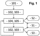
- the figure 1 shows a diagram of the process steps 100.
- the control module displays on the selection screen ES a proposal P1 of a first optical glass V1 and a proposal P2 of a second optical glass V2.
- a second step 102 illustrated in figure 3a the operator selects the proposition P1 of the first optical glass V1 and the command receives the selection of the proposal P1 of the first optical glass V1.
- the proposition P1 of the first optical lens V1 is preferably automatically selected, without intervention by the operator.
- the control module upon receipt of the selection of the proposition P1 of the first optical glass V1, the control module arranges said first optical glass V1 in a location of the automatic refractor head T. If this location is already occupied by a Another element, the control module begins by removing the other element to be able to place the first optical glass V1.
- the figure 3b illustrates the arrangement according to the third step 103.
- the control module when it takes place for the first time, on receipt of the selection of the proposition P1 of the first optical glass V1, the control module also preferably displays on the selection screen ES first and third symbols validation S1, S3, the first symbol S1 indicating that the first and second glasses V1, V2 are the same, the third symbol S3 indicating that the first optical glass V1 is better than the second optical glass V2, without however the first and third validation symbols S1, S3 displayed cannot be selected.
- the figure 3a illustrates this preferential display.
- a second validation symbol S2 indicating that the second optical glass V2 is better than the first optical glass V1 could be displayed additionally while not being selectable either.
- the control module upon receipt of the selection of the proposal P1 from the first optical glass V1, the control module does not display any validation symbol on the selection screen ES .
- the control module receives a selection of the proposition P2 of the second optical glass V2.
- a fifth step 105 upon receipt of the selection of the proposition P2 of the second optical glass V2, the control module arranges said second optical glass V2 in the location of the automatic refractor head T - starting by removing the first glass optical V1.
- the figure 4a illustrates the arrangement according to the fifth step 105.
- the control module on receipt of the selection of the proposition P2 of the second optical lens V2, the control module also displays on the selection screen ES the first validation symbol S1 and a second validation symbol S2 indicating that the second optical glass V2 is better than the first optical glass V1, each of the first and second symbols S1, S2 being selectable.
- the third validation symbol S3 which makes it possible to indicate that the first lens V1 is better than the second lens V2, is not selectable and preferably it is not displayed at all.
- the figure 4a illustrates this preferential display.
- the control module further displays on the selection screen ES the first symbol of validation S1 and a third validation symbol S3 indicating that the first optical glass V1 is better than the second optical glass V2, each of the first and third symbols S1, S3 being selectable.
- the second validation symbol S2 which makes it possible to indicate that the second optical glass V2 is better than the first optical glass V1, is not selectable and preferably it is not displayed at all.
- the figure 3a illustrates this preferential display.
- the figures 3b and 4b show an example according to which the automatic refractor head is used in a right eye monocular: the first and second optical glasses V1, V2 are successively arranged in the location corresponding to the right eye while the location corresponding to the left eye is occupied by an opaque cache.
- the invention naturally also applies to left eye monocular cases, by successively arranging the first and second optical glasses V1, V2 in the location corresponding to the left eye while the location corresponding to the right eye is occupied by an opaque cover; and binocular, by testing a first set of a first optical lens for the right eye and a first optical lens for the left eye, then a second set of a second optical lens for the right eye and a second optical lens for the left eye.
- the first optical lens for the right eye and the first optical lens for the left eye may be the same or different; likewise the second optical lens for the right eye and the second optical lens for the left eye may be the same or different.
- the control module for its part comprises means for simultaneously displaying on the selection screen ES the proposal P1 of the first optical glass V1, the proposal P2 of the second optical glass V2 and all or part of the validation symbols S1, S2, S3 each indicating a possible result of a comparison between the first and second optical glasses V1, V2, preferably either the first and second symbols S1, S2, or the first and third symbols S1, S3.
- the control module also comprises means for receiving a selection of the proposition P1, P2 of the first or of the second optical glass V1, V2 or of a validation symbol S1, S2, S3.
- the control module can only receive a selection of a proposition P1, P2 or of a symbol S1, S2, S3 if said proposition or said symbol is displayed beforehand. Any displayed proposal is selectable but not all displayed symbol is necessarily selectable.
- control module comprises means for, on receipt of the selection of the proposition P1, P2 of the first or of the second optical glass V1, V2, arranging said first or second optical glass V1, V2 in a location of the automatic refractor head T.
- control module according to the second aspect of the invention comprises means for displaying a test symbol or a plurality of test symbols on the reading screen.
- the control module according to the second aspect of the invention can also include means for duplicating on the reading screen all or part of the display produced on the selection screen and / or for duplicating on the selection screen. all or part of the display produced on the reading screen.
- the operator interacts with the ES selection screen to select a proposal P1, P2 or a symbol S1, S2, S3 displayed.
- the subject examined interacts with the reading screen to read or identify, through the automatic refractor head T, one or more test symbols displayed.
- the selection screen ES and the reading screen are preferably two separate screens, for example a tablet for the selection screen ES and a projection screen for the reading screen.
- the display produced on the ES selection screen and on the reading screen can be identical or differentiated.
- the selection screen ES and the reading screen can be one and the same screen, for example a projection screen, therefore with one and only one display.
- the operator is defined as the one who interacts with the ES selection screen and the control module.
- the operator is typically a practitioner, such as an ophthalmologist, an optician or even, in the context of the present invention, an assistant without particular skills in refractive physics and physiology of the visual system.
- the subject examined is defined as being the one who views the reading screen through the automatic refractor head T.
- the subject examined is typically a patient or client of the practitioner.
- the subject examined can itself be an operator.
- the examined subject may be the sole operator in the absence of any practitioner.
- two distinct operators for example the examined subject and a practitioner, can take turns.
- the subject examined is an operator, either the reading screen forms a single screen with the selection screen, or the reading screen is a second selection screen.
- the first and second markers allow the examined subject to know which glass proposal he is testing.
- the first and second markers have a size which is adjusted so that their angle of discrimination is large enough to be perceived by the subject being examined even if he or she otherwise fails to read or identify the marks. test symbols.
- the first and second markers are preferably displayed in first and second distinct areas of the reading screen.
- the system according to the third aspect of the invention comprises the control module according to the second aspect of the invention as well as the selection screen ES.
- the ES selection screen can be integrated with the control module. This is for example the case with a control module in the form of a touchscreen tablet or laptop. Alternatively, the ES selection screen can be separate from the control module. This is for example the case of a control module connected with a remote screen of the computer screen, television screen or projection screen type.
- the system according to the third aspect of the invention can also include the reading screen.
- the ES selection screen and the playback screen can be one and the same screen or two separate screens.
- Each selection step either of a proposal P1, P2 of a lens, or of a validation symbol S1, S2, S3, is carried out by the operator performing a selection action in interaction with the selection screen ES.
- the selection action can be carried out in different ways, several non-limiting examples of which are listed below.
- the selection action is performed on a proposal P1, P2 or a selectable validation symbol S1, S2, S3, it results in the transmission of a selection to the control module, which takes it into account by carrying out the steps of display and / or arrangement as previously described. If the selection action is performed on a proposal P1, P2 or a validation symbol S1, S2, S3 which is not selectable, it does not result in any transmission of the selection to the control module.
- the selection action is carried out on a proposal P1, P2 or a selectable validation symbol S1, S2, S3, it preferably results in a graphic modification of the appearance of the display so as to inform the operator. that its selection action has worked, while if the selection action is performed on a proposal P1, P2 or a validation symbol S1, S2, S3 that cannot be selected, it does not cause any graphic modification of the appearance of the 'display so as to inform the operator that his selection action has not worked.
- the selection action is preferably carried out by means of a touchscreen ES selection screen: the operator touches an area of the screen on which there is a proposal P1, P2 of a lens or a validation symbol S1, S2 , S3 in order to select said proposition or said validation symbol.
- each proposition P1, P2 of a lens is identified by a word or group of words which is specific to it, for example the word “one” for the proposition P1 of the first glass and the word “two” for the proposition P2 of the second glass;
- the first validation symbol S1 (the one which indicates that the first and second optical glasses are the same) is identified by a word or group of words which is specific to it, for example the word “same” or “equal”.
- second and third validation symbols S2, S3 are not simultaneously selectable, they are for their part advantageously identified both by one and the same word or group of words which is specific to them, for example the word “better” or " to validate ".
- the operator pronounces a word or group of words in order to select the corresponding proposition or symbol of validation.
- each proposition P1, P2 of a glass is identified by a position or a movement of the hand which is specific to it, for example the raised index for the proposition P1 of the first glass and the index and middle fingers surveys for proposition P2 of the second glass; likewise, the first validation symbol S1 (the one which indicates that the first and second optical glasses are the same) is identified by a position or a movement of the hand which is specific to it, for example the closed fist.
- the second and third validation symbols S2, S3 are not simultaneously selectable, they are for their part advantageously identified both by one and the same position or movement of the hand which is specific to them, for example the raised thumb.
- the operator uses a finger, for example his index finger, as a pointer in order to designate the area of the screen on which the proposal or the validation symbol that he wishes to select is located.
- the operator positions his hand or makes a movement in order to select the proposal or the corresponding validation symbol.
- the different selection actions of the method 100 according to the first aspect of the invention can all be carried out in one and the same way, for example by means of a touch selection screen.
- a combination of several different techniques can be used to perform the different selection actions of the method 100, for example the actions for selecting a proposition via a touch selection screen or via a gesture command, and the actions for selecting a proposal. '' a validation symbol via a voice command, etc.
Landscapes
- Health & Medical Sciences (AREA)
- Life Sciences & Earth Sciences (AREA)
- Physics & Mathematics (AREA)
- Ophthalmology & Optometry (AREA)
- General Health & Medical Sciences (AREA)
- Surgery (AREA)
- Biophysics (AREA)
- Heart & Thoracic Surgery (AREA)
- Medical Informatics (AREA)
- Molecular Biology (AREA)
- Engineering & Computer Science (AREA)
- Animal Behavior & Ethology (AREA)
- Biomedical Technology (AREA)
- Public Health (AREA)
- Veterinary Medicine (AREA)
- General Physics & Mathematics (AREA)
- Optics & Photonics (AREA)
- Eyeglasses (AREA)
- User Interface Of Digital Computer (AREA)
- Eye Examination Apparatus (AREA)
Claims (10)
- Vergleichsverfahren (100) eines ersten und eines zweiten optischen Glases (V1, V2) mittels eines automatischen Rückstrahlerkopfes (T), der durch ein Steuermodul gesteuert wird, wobei das Verfahren (100) die folgenden Schritte umfasst, nach denen das Steuermodul:- auf einem Auswahlbildschirm (ES) einen Vorschlag (P1) eines ersten optischen Glases (V1) und einen Vorschlag (P2) eines zweiten optischen Glases (V2) anzeigt (101);- eine Auswahl des Vorschlags (P1) des ersten optischen Glases (V1) empfängt (102);- das erste optische Glas (V1) beim Empfang der Auswahl des Vorschlags (P1) des ersten optischen Glases (V1) an einer Stelle des automatischen Rückstrahlerkopfes (T) anordnet (103);- eine Auswahl des Vorschlags (P2) des zweiten optischen Glases (V2) empfängt (104);- das zweite optische Glas (V2) beim Empfang der Auswahl des Vorschlags (P2) des zweiten optischen Glases (V2) an der Stelle des automatischen Rückstrahlerkopfes (T) anordnet (105);- auf dem Auswahlbildschirm (ES) eine Vielzahl von Bestätigungssymbolen (S1, S2, S3) anzeigt (103, 105), die jeweils ein mögliches Ergebnis des Vergleichs angeben;wobei das Verfahren (100) derart ist, dass:- wenn das Steuermodul die Auswahl des Vorschlags (P1) des ersten optischen Glases (V1) zum ersten Mal empfängt, ist der Vorschlag (P2) des zweiten optischen Glases (V2) auf dem Auswahlbildschirm (ES) auswählbar und kein Bestätigungssymbol (S1, S2, S3) ist auf dem Auswahlbildschirm (ES) auswählbar;- wenn das Steuermodul die Auswahl des Vorschlags (P2) des zweiten optischen Glases (V2) empfängt, ist der Vorschlag (P1) des ersten optischen Glases (V1) auf dem Auswahlbildschirm (ES) auswählbar und das erste und das zweite Bestätigungssymbol (S1, S2) sind auf dem Auswahlbildschirm (ES) auswählbar, wobei das erste Symbol (S1) angibt, dass das erste und das zweite optische Glas (V1, V2) gleich sind und wobei das zweite Symbol (S2) angibt, dass das zweite optische Glas (V2) besser ist als das erste optische Glas (V1);- wenn das Steuermodul die Auswahl des Vorschlags (P1) des ersten optischen Glases (V1) zum zweiten Mal oder häufiger empfängt, ist der Vorschlag (P2) des zweiten optischen Glases (V2) auf dem Auswahlbildschirm (ES) auswählbar und das erste Symbol (S1) und ein drittes Symbol (S3) sind auf dem Auswahlbildschirm (ES) auswählbar, wobei das dritte Symbol (S3) angibt, dass das erste optische Glas (V1) besser ist als das zweite optische Glas (V2).
- Verfahren (100) gemäß dem voranstehenden Anspruch, dadurch gekennzeichnet, dass, wenn der zweite Schritt (102) zum ersten Mal erfolgt ist, dieser von dem Steuermodul ohne Eingreifen eines Operators automatisch realisiert wird.
- Verfahren (100) gemäß irgendeinem der voranstehenden Ansprüche, dadurch gekennzeichnet, dass, wenn das Steuermodul die Auswahl des Vorschlags (P1) des ersten optischen Glases (V1) zum ersten Mal empfängt, das Steuermodul kein Bestätigungssymbol (S1, S2, S3) auf dem Auswahlbildschirm (ES) anzeigt.
- Verfahren (100) gemäß irgendeinem der voranstehenden Ansprüche, dadurch gekennzeichnet, dass, wenn das Steuermodul die Auswahl des Vorschlags (P2) des zweiten optischen Glases (V2) empfängt, das Steuermodul das erste und das zweite Bestätigungssymbol (S1, S2) anzeigt, das dritte Bestätigungssymbol (S3) aber nicht.
- Verfahren (100) gemäß irgendeinem der voranstehenden Ansprüche, dadurch gekennzeichnet, dass, wenn das Steuermodul die Auswahl des Vorschlags (P1) des ersten optischen Glases (V1) zum zweiten Mal oder häufiger empfängt, das Steuermodul das erste und das dritte Bestätigungssymbol (S1, S3) anzeigt, das zweite Bestätigungsmodul (S2) aber nicht.
- Steuermodul eines automatischen Rückstrahlerkopfes (T) zum Umsetzen eines Vergleichsverfahrens (100) des ersten und des zweiten optischen Glases gemäß irgendeinem der voranstehenden Ansprüche, wobei das Steuermodul aufweist:- Mittel zum gleichzeitigen Anzeigen eines Vorschlags (P1) eines ersten optischen Glases (V1), eines Vorschlags (P2) eines zweiten optischen Glases (V2) und eine ganze oder teilweise Vielzahl von Bestätigungssymbolen (S1, S2, S3) auf einem Auswahlbildschirm (ES), die jeweils ein mögliches Ergebnis eines Vergleichs zwischen dem ersten und dem zweiten optischen Glas (V1, V2) angeben;- Mittel zum Empfangen einer Auswahl des Vorschlages (P1, P2) des ersten oder des zweiten optischen Glases (V1, V2) oder eines Bestätigungssymboles (S1, S2, S3);- Mittel zum Anordnen des genannten ersten oder des zweiten optischen Glases (V1, V2) an einer Stelle des automatischen Rückstrahlkopfes (T) beim Empfang der Auswahl des Vorschlags (P1, P2) des ersten oder des zweiten optischen Glases (V1, V2);wobei die Anzeigemittel auf dem Auswahlbildschirm und die Empfangsmittel einer Auswahl derart sind, dass:- wenn das Steuermodul die Auswahl des Vorschlags (P1) des ersten optischen Glases (V1) zum ersten Mal empfängt, ist der Vorschlag (P2) des zweiten optischen Glases (V2) auf dem Auswahlbildschirm (ES) auswählbar und kein Bestätigungssymbol (S1, S2 S3) ist auf dem Auswahlbildschirm auswählbar;- wenn das Steuermodul die Auswahl des Vorschlags (P2) des zweiten optischen Glases (V2) empfängt, ist der Vorschlag (P1) des ersten optischen Glases (V1) auf dem Auswahlbildschirm (ES) auswählbar und das erste und das zweite Bestätigungssymbol (S1, S2) sind auf dem Auswählbildschirm (ES) auswählbar, wobei das erste Symbol (S1) angibt, dass das erste und das zweite optische Glas ((V1, V2) gleich sind und wobei das zweite Symbol (S2) angibt, dass das zweite optische Glas (V2) besser ist als das erste optische Glas (V1);- wenn das Steuermodul die Auswahl des Vorschlags (P1) des ersten optischen Glases (V1) zum zweiten Mal oder häufiger empfängt, ist der Vorschlag (P2) des zweiten Glases (V2) auf dem Auswahlbildschirm (ES) auswählbar und das erste Symbol (S1) und ein drittes Symbol (S3) sind auf dem Auswahlbildschirm (ES) auswählbar, wobei das dritte Symbol (S3) angibt, dass das erste optische Glas (V1) besser ist als das zweite optische Glas (V2).
- System zum Umsetzen eines Vergleichsverfahrens (100) des ersten und des zweiten optischen Glases gemäß irgendeinem der Ansprüche 1 bis 5, umfassend das Steuermodul eines automatischen Rückstrahlerkopfes (T) gemäß Anspruch 6 sowie den Auswahlbildschirm (ES).
- System gemäß dem voranstehenden Anspruch, dadurch gekennzeichnet, dass es darüber hinaus einen Lesebildschirm umfasst.
- System gemäß dem voranstehenden Anspruch, dadurch gekennzeichnet, dass der Auswahlbildschirm (ES) und der Lesebildschirm zwei unterschiedliche Bildschirme sind.
- System gemäß Anspruch 8, dadurch gekennzeichnet, dass der Auswahlbildschirm (ES) und der Lesebildschirm ein und derselbe Bildschirm sind.
Priority Applications (1)
| Application Number | Priority Date | Filing Date | Title |
|---|---|---|---|
| PL19706277T PL3755202T3 (pl) | 2018-02-23 | 2019-02-21 | Sposób porównywania soczewek optycznych, związany z nim moduł sterujący oraz układ |
Applications Claiming Priority (2)
| Application Number | Priority Date | Filing Date | Title |
|---|---|---|---|
| FR1851617A FR3078248B1 (fr) | 2018-02-23 | 2018-02-23 | Procede de comparaison de verres optiques, module de commande et systeme associes |
| PCT/EP2019/054344 WO2019162394A1 (fr) | 2018-02-23 | 2019-02-21 | Procede de comparaison de verres optiques, module de commande et systeme associes |
Publications (2)
| Publication Number | Publication Date |
|---|---|
| EP3755202A1 EP3755202A1 (de) | 2020-12-30 |
| EP3755202B1 true EP3755202B1 (de) | 2021-10-20 |
Family
ID=62167538
Family Applications (1)
| Application Number | Title | Priority Date | Filing Date |
|---|---|---|---|
| EP19706277.1A Active EP3755202B1 (de) | 2018-02-23 | 2019-02-21 | Verfahren zum vergleich optischer linsen, zugehöriges steuermodul und system |
Country Status (8)
| Country | Link |
|---|---|
| US (1) | US11860344B2 (de) |
| EP (1) | EP3755202B1 (de) |
| CN (1) | CN111989029B (de) |
| DK (1) | DK3755202T3 (de) |
| FR (1) | FR3078248B1 (de) |
| LT (1) | LT3755202T (de) |
| PL (1) | PL3755202T3 (de) |
| WO (1) | WO2019162394A1 (de) |
Family Cites Families (16)
| Publication number | Priority date | Publication date | Assignee | Title |
|---|---|---|---|---|
| US3969020A (en) * | 1973-12-28 | 1976-07-13 | Giles C. Clegg, Jr. | Automatic refraction apparatus and method |
| CN1105980C (zh) * | 1998-02-03 | 2003-04-16 | 西乡刚 | 眼镜试戴模拟方法 |
| JP2001340296A (ja) * | 2000-03-30 | 2001-12-11 | Topcon Corp | 検眼システム |
| DE10033983A1 (de) * | 2000-04-27 | 2001-10-31 | Frank Mothes | Einrichtung zur Bestimmung der Brillenglas-Zentrierdaten |
| US6817713B2 (en) * | 2000-10-27 | 2004-11-16 | Hoya Corporation | Spectacle lens manufacturing method and spectacle lens supply system |
| JP2006068417A (ja) * | 2004-09-06 | 2006-03-16 | Topcon Corp | 検眼装置 |
| EP2490065A1 (de) * | 2011-02-18 | 2012-08-22 | ESSILOR INTERNATIONAL (Compagnie Générale d'Optique) | Verfahren zur Bestimmung von optischen Zielfunktionen |
| FR2988494B1 (fr) * | 2012-03-20 | 2015-04-03 | Essilor Int | Methode de fabrication d'une lentille ophtalmique correctrice de lunettes personnalisee pour un porteur |
| GB2525817B (en) * | 2013-03-12 | 2020-02-26 | Opternative Inc | Computerized refraction and astigmatism determination |
| US9207466B2 (en) * | 2013-11-26 | 2015-12-08 | Johnson & Johnson Vision Care, Inc. | Determining lens alignment on an eye using optical wavefronts |
| FR3018120B1 (fr) * | 2014-02-28 | 2018-07-27 | Essilor International | Procede et dispositif de selection d’un equipement comprenant au moins un verre ophtalmique et une monture, procede et dispositif d’accompagnement du choix d’un tel equipement |
| TW201629582A (zh) * | 2014-11-05 | 2016-08-16 | 布萊恩荷登視覺協會 | 有關用於抑制近視加深之單視及多焦點鏡片的系統及方法 |
| EP3230792B1 (de) * | 2014-12-08 | 2023-05-31 | Essilor International | Computerimplementiertes verfahren zur berechnung eines optischen linsensystems eines brillenglases für einen kontaktlinsenträger |
| US10394052B2 (en) * | 2015-03-10 | 2019-08-27 | Essilor International | Method for determining a pair of ophthalmic lenses |
| HK1255158A1 (zh) * | 2015-07-29 | 2019-08-09 | Johnson & Johnson Vision Care, Inc. | 用於确定矫正视力的系统和方法 |
| FR3059537B1 (fr) * | 2016-12-07 | 2019-05-17 | Essilor International | Appareil et procede de mesure de refraction oculaire subjective de haute resolution en puissance optique spherique et/ou cylindrique |
-
2018
- 2018-02-23 FR FR1851617A patent/FR3078248B1/fr not_active Expired - Fee Related
-
2019
- 2019-02-21 US US16/971,923 patent/US11860344B2/en active Active
- 2019-02-21 WO PCT/EP2019/054344 patent/WO2019162394A1/fr not_active Ceased
- 2019-02-21 DK DK19706277.1T patent/DK3755202T3/da active
- 2019-02-21 LT LTEPPCT/EP2019/054344T patent/LT3755202T/lt unknown
- 2019-02-21 PL PL19706277T patent/PL3755202T3/pl unknown
- 2019-02-21 CN CN201980023055.5A patent/CN111989029B/zh active Active
- 2019-02-21 EP EP19706277.1A patent/EP3755202B1/de active Active
Also Published As
| Publication number | Publication date |
|---|---|
| US11860344B2 (en) | 2024-01-02 |
| US20210088761A1 (en) | 2021-03-25 |
| CN111989029A (zh) | 2020-11-24 |
| FR3078248A1 (fr) | 2019-08-30 |
| EP3755202A1 (de) | 2020-12-30 |
| CN111989029B (zh) | 2024-07-23 |
| DK3755202T3 (da) | 2022-01-17 |
| PL3755202T3 (pl) | 2022-03-07 |
| FR3078248B1 (fr) | 2020-03-06 |
| WO2019162394A1 (fr) | 2019-08-29 |
| LT3755202T (lt) | 2022-01-25 |
Similar Documents
| Publication | Publication Date | Title |
|---|---|---|
| US20230320581A1 (en) | Computerized testing and determination of a visual field of a patient | |
| CA2910292C (fr) | Procede de personnalisation d'un dispositif electronique afficheur d'image | |
| EP2741656B1 (de) | Vorrichtung zur bestimmung einer für eine person geeigneten gruppe von sehhilfen | |
| CA2914696C (fr) | Procede de determination d'au moins une valeur d'un parametre de personnalisation d'un equipement de compensation visuelle | |
| EP3082565B1 (de) | Vorrichtung und verfahren zum screening von sichtdefekten und zur messung der sehschärfe eines benutzers | |
| EP3755202B1 (de) | Verfahren zum vergleich optischer linsen, zugehöriges steuermodul und system | |
| EP3755199B1 (de) | Sehtestverfahren, entsprechendes steuermodul und system | |
| FR2755631A1 (fr) | Systeme et procede de blocage d'une lentille | |
| EP3755200B1 (de) | Sehtestverfahren sowie zugehöriges steuermodul und system | |
| WO2025068195A1 (fr) | Procédé de détermination d'une valeur de phorie d'un sujet | |
| WO2025068191A1 (fr) | Procédé de détermination d'au moins une valeur de phorie d'un sujet | |
| HK40038508A (en) | Method for comparing optical lenses, associated control module and system | |
| WO2023174883A1 (fr) | Procédé d'évaluation de l'astigmatisme d'un individu | |
| EP3793424B1 (de) | Vorrichtung, verfahren und kabine zur automatischen bestimmung der subjektiven augenbrechung eines patienten | |
| EP4640134A1 (de) | Bestimmung eines fusionsrestwertes eines subjektes |
Legal Events
| Date | Code | Title | Description |
|---|---|---|---|
| STAA | Information on the status of an ep patent application or granted ep patent |
Free format text: STATUS: UNKNOWN |
|
| STAA | Information on the status of an ep patent application or granted ep patent |
Free format text: STATUS: THE INTERNATIONAL PUBLICATION HAS BEEN MADE |
|
| PUAI | Public reference made under article 153(3) epc to a published international application that has entered the european phase |
Free format text: ORIGINAL CODE: 0009012 |
|
| STAA | Information on the status of an ep patent application or granted ep patent |
Free format text: STATUS: REQUEST FOR EXAMINATION WAS MADE |
|
| 17P | Request for examination filed |
Effective date: 20200909 |
|
| AK | Designated contracting states |
Kind code of ref document: A1 Designated state(s): AL AT BE BG CH CY CZ DE DK EE ES FI FR GB GR HR HU IE IS IT LI LT LU LV MC MK MT NL NO PL PT RO RS SE SI SK SM TR |
|
| AX | Request for extension of the european patent |
Extension state: BA ME |
|
| DAV | Request for validation of the european patent (deleted) | ||
| DAX | Request for extension of the european patent (deleted) | ||
| GRAP | Despatch of communication of intention to grant a patent |
Free format text: ORIGINAL CODE: EPIDOSNIGR1 |
|
| STAA | Information on the status of an ep patent application or granted ep patent |
Free format text: STATUS: GRANT OF PATENT IS INTENDED |
|
| INTG | Intention to grant announced |
Effective date: 20210616 |
|
| GRAS | Grant fee paid |
Free format text: ORIGINAL CODE: EPIDOSNIGR3 |
|
| GRAA | (expected) grant |
Free format text: ORIGINAL CODE: 0009210 |
|
| STAA | Information on the status of an ep patent application or granted ep patent |
Free format text: STATUS: THE PATENT HAS BEEN GRANTED |
|
| AK | Designated contracting states |
Kind code of ref document: B1 Designated state(s): AL AT BE BG CH CY CZ DE DK EE ES FI FR GB GR HR HU IE IS IT LI LT LU LV MC MK MT NL NO PL PT RO RS SE SI SK SM TR |
|
| REG | Reference to a national code |
Ref country code: GB Ref legal event code: FG4D Free format text: NOT ENGLISH |
|
| REG | Reference to a national code |
Ref country code: CH Ref legal event code: EP |
|
| REG | Reference to a national code |
Ref country code: IE Ref legal event code: FG4D Free format text: LANGUAGE OF EP DOCUMENT: FRENCH |
|
| REG | Reference to a national code |
Ref country code: DE Ref legal event code: R096 Ref document number: 602019008541 Country of ref document: DE |
|
| REG | Reference to a national code |
Ref country code: AT Ref legal event code: REF Ref document number: 1439228 Country of ref document: AT Kind code of ref document: T Effective date: 20211115 |
|
| REG | Reference to a national code |
Ref country code: FI Ref legal event code: FGE |
|
| REG | Reference to a national code |
Ref country code: DK Ref legal event code: T3 Effective date: 20220113 |
|
| REG | Reference to a national code |
Ref country code: SE Ref legal event code: TRGR |
|
| REG | Reference to a national code |
Ref country code: NL Ref legal event code: FP |
|
| REG | Reference to a national code |
Ref country code: NO Ref legal event code: T2 Effective date: 20211020 |
|
| REG | Reference to a national code |
Ref country code: AT Ref legal event code: MK05 Ref document number: 1439228 Country of ref document: AT Kind code of ref document: T Effective date: 20211020 Ref country code: EE Ref legal event code: FG4A Ref document number: E021846 Country of ref document: EE Effective date: 20220107 |
|
| PG25 | Lapsed in a contracting state [announced via postgrant information from national office to epo] |
Ref country code: RS Free format text: LAPSE BECAUSE OF FAILURE TO SUBMIT A TRANSLATION OF THE DESCRIPTION OR TO PAY THE FEE WITHIN THE PRESCRIBED TIME-LIMIT Effective date: 20211020 Ref country code: BG Free format text: LAPSE BECAUSE OF FAILURE TO SUBMIT A TRANSLATION OF THE DESCRIPTION OR TO PAY THE FEE WITHIN THE PRESCRIBED TIME-LIMIT Effective date: 20220120 Ref country code: AT Free format text: LAPSE BECAUSE OF FAILURE TO SUBMIT A TRANSLATION OF THE DESCRIPTION OR TO PAY THE FEE WITHIN THE PRESCRIBED TIME-LIMIT Effective date: 20211020 |
|
| PG25 | Lapsed in a contracting state [announced via postgrant information from national office to epo] |
Ref country code: IS Free format text: LAPSE BECAUSE OF FAILURE TO SUBMIT A TRANSLATION OF THE DESCRIPTION OR TO PAY THE FEE WITHIN THE PRESCRIBED TIME-LIMIT Effective date: 20220220 Ref country code: PT Free format text: LAPSE BECAUSE OF FAILURE TO SUBMIT A TRANSLATION OF THE DESCRIPTION OR TO PAY THE FEE WITHIN THE PRESCRIBED TIME-LIMIT Effective date: 20220221 Ref country code: HR Free format text: LAPSE BECAUSE OF FAILURE TO SUBMIT A TRANSLATION OF THE DESCRIPTION OR TO PAY THE FEE WITHIN THE PRESCRIBED TIME-LIMIT Effective date: 20211020 Ref country code: GR Free format text: LAPSE BECAUSE OF FAILURE TO SUBMIT A TRANSLATION OF THE DESCRIPTION OR TO PAY THE FEE WITHIN THE PRESCRIBED TIME-LIMIT Effective date: 20220121 Ref country code: ES Free format text: LAPSE BECAUSE OF FAILURE TO SUBMIT A TRANSLATION OF THE DESCRIPTION OR TO PAY THE FEE WITHIN THE PRESCRIBED TIME-LIMIT Effective date: 20211020 |
|
| REG | Reference to a national code |
Ref country code: DE Ref legal event code: R097 Ref document number: 602019008541 Country of ref document: DE |
|
| PG25 | Lapsed in a contracting state [announced via postgrant information from national office to epo] |
Ref country code: SM Free format text: LAPSE BECAUSE OF FAILURE TO SUBMIT A TRANSLATION OF THE DESCRIPTION OR TO PAY THE FEE WITHIN THE PRESCRIBED TIME-LIMIT Effective date: 20211020 Ref country code: SK Free format text: LAPSE BECAUSE OF FAILURE TO SUBMIT A TRANSLATION OF THE DESCRIPTION OR TO PAY THE FEE WITHIN THE PRESCRIBED TIME-LIMIT Effective date: 20211020 Ref country code: CZ Free format text: LAPSE BECAUSE OF FAILURE TO SUBMIT A TRANSLATION OF THE DESCRIPTION OR TO PAY THE FEE WITHIN THE PRESCRIBED TIME-LIMIT Effective date: 20211020 |
|
| PLBE | No opposition filed within time limit |
Free format text: ORIGINAL CODE: 0009261 |
|
| STAA | Information on the status of an ep patent application or granted ep patent |
Free format text: STATUS: NO OPPOSITION FILED WITHIN TIME LIMIT |
|
| 26N | No opposition filed |
Effective date: 20220721 |
|
| PG25 | Lapsed in a contracting state [announced via postgrant information from national office to epo] |
Ref country code: MC Free format text: LAPSE BECAUSE OF FAILURE TO SUBMIT A TRANSLATION OF THE DESCRIPTION OR TO PAY THE FEE WITHIN THE PRESCRIBED TIME-LIMIT Effective date: 20211020 |
|
| REG | Reference to a national code |
Ref country code: CH Ref legal event code: PL |
|
| PG25 | Lapsed in a contracting state [announced via postgrant information from national office to epo] |
Ref country code: LU Free format text: LAPSE BECAUSE OF NON-PAYMENT OF DUE FEES Effective date: 20220221 Ref country code: AL Free format text: LAPSE BECAUSE OF FAILURE TO SUBMIT A TRANSLATION OF THE DESCRIPTION OR TO PAY THE FEE WITHIN THE PRESCRIBED TIME-LIMIT Effective date: 20211020 |
|
| PG25 | Lapsed in a contracting state [announced via postgrant information from national office to epo] |
Ref country code: SI Free format text: LAPSE BECAUSE OF FAILURE TO SUBMIT A TRANSLATION OF THE DESCRIPTION OR TO PAY THE FEE WITHIN THE PRESCRIBED TIME-LIMIT Effective date: 20211020 |
|
| PG25 | Lapsed in a contracting state [announced via postgrant information from national office to epo] |
Ref country code: LI Free format text: LAPSE BECAUSE OF NON-PAYMENT OF DUE FEES Effective date: 20220228 Ref country code: IE Free format text: LAPSE BECAUSE OF NON-PAYMENT OF DUE FEES Effective date: 20220221 Ref country code: CH Free format text: LAPSE BECAUSE OF NON-PAYMENT OF DUE FEES Effective date: 20220228 |
|
| PG25 | Lapsed in a contracting state [announced via postgrant information from national office to epo] |
Ref country code: IT Free format text: LAPSE BECAUSE OF FAILURE TO SUBMIT A TRANSLATION OF THE DESCRIPTION OR TO PAY THE FEE WITHIN THE PRESCRIBED TIME-LIMIT Effective date: 20211020 |
|
| P01 | Opt-out of the competence of the unified patent court (upc) registered |
Effective date: 20230525 |
|
| PG25 | Lapsed in a contracting state [announced via postgrant information from national office to epo] |
Ref country code: MK Free format text: LAPSE BECAUSE OF FAILURE TO SUBMIT A TRANSLATION OF THE DESCRIPTION OR TO PAY THE FEE WITHIN THE PRESCRIBED TIME-LIMIT Effective date: 20211020 Ref country code: CY Free format text: LAPSE BECAUSE OF FAILURE TO SUBMIT A TRANSLATION OF THE DESCRIPTION OR TO PAY THE FEE WITHIN THE PRESCRIBED TIME-LIMIT Effective date: 20211020 |
|
| PG25 | Lapsed in a contracting state [announced via postgrant information from national office to epo] |
Ref country code: HU Free format text: LAPSE BECAUSE OF FAILURE TO SUBMIT A TRANSLATION OF THE DESCRIPTION OR TO PAY THE FEE WITHIN THE PRESCRIBED TIME-LIMIT; INVALID AB INITIO Effective date: 20190221 |
|
| PG25 | Lapsed in a contracting state [announced via postgrant information from national office to epo] |
Ref country code: TR Free format text: LAPSE BECAUSE OF FAILURE TO SUBMIT A TRANSLATION OF THE DESCRIPTION OR TO PAY THE FEE WITHIN THE PRESCRIBED TIME-LIMIT Effective date: 20211020 |
|
| PG25 | Lapsed in a contracting state [announced via postgrant information from national office to epo] |
Ref country code: MT Free format text: LAPSE BECAUSE OF FAILURE TO SUBMIT A TRANSLATION OF THE DESCRIPTION OR TO PAY THE FEE WITHIN THE PRESCRIBED TIME-LIMIT Effective date: 20211020 |
|
| PGFP | Annual fee paid to national office [announced via postgrant information from national office to epo] |
Ref country code: NL Payment date: 20260226 Year of fee payment: 8 |
|
| PGFP | Annual fee paid to national office [announced via postgrant information from national office to epo] |
Ref country code: SE Payment date: 20260225 Year of fee payment: 8 |
|
| PGFP | Annual fee paid to national office [announced via postgrant information from national office to epo] |
Ref country code: LT Payment date: 20260218 Year of fee payment: 8 Ref country code: GB Payment date: 20260225 Year of fee payment: 8 |
|
| PGFP | Annual fee paid to national office [announced via postgrant information from national office to epo] |
Ref country code: DK Payment date: 20260223 Year of fee payment: 8 Ref country code: NO Payment date: 20260223 Year of fee payment: 8 Ref country code: DE Payment date: 20260324 Year of fee payment: 8 |
|
| PGFP | Annual fee paid to national office [announced via postgrant information from national office to epo] |
Ref country code: RO Payment date: 20260223 Year of fee payment: 8 Ref country code: FI Payment date: 20260223 Year of fee payment: 8 Ref country code: BE Payment date: 20260226 Year of fee payment: 8 |
|
| PGFP | Annual fee paid to national office [announced via postgrant information from national office to epo] |
Ref country code: FR Payment date: 20260227 Year of fee payment: 8 |
|
| PGFP | Annual fee paid to national office [announced via postgrant information from national office to epo] |
Ref country code: PL Payment date: 20260219 Year of fee payment: 8 |
|
| PGFP | Annual fee paid to national office [announced via postgrant information from national office to epo] |
Ref country code: EE Payment date: 20260227 Year of fee payment: 8 Ref country code: LV Payment date: 20260226 Year of fee payment: 8 |