EP3755116B1 - Verfahren zur verarbeitung der einrichtung einer ma-pdu-sitzung sowie amf-knoten und smf-knoten - Google Patents
Verfahren zur verarbeitung der einrichtung einer ma-pdu-sitzung sowie amf-knoten und smf-knoten Download PDFInfo
- Publication number
- EP3755116B1 EP3755116B1 EP19755089.0A EP19755089A EP3755116B1 EP 3755116 B1 EP3755116 B1 EP 3755116B1 EP 19755089 A EP19755089 A EP 19755089A EP 3755116 B1 EP3755116 B1 EP 3755116B1
- Authority
- EP
- European Patent Office
- Prior art keywords
- access
- pdu session
- smf
- pdu
- node
- Prior art date
- Legal status (The legal status is an assumption and is not a legal conclusion. Google has not performed a legal analysis and makes no representation as to the accuracy of the status listed.)
- Active
Links
Images


Classifications
-
- H—ELECTRICITY
- H04—ELECTRIC COMMUNICATION TECHNIQUE
- H04W—WIRELESS COMMUNICATION NETWORKS
- H04W76/00—Connection management
- H04W76/10—Connection setup
- H04W76/15—Setup of multiple wireless link connections
- H04W76/16—Involving different core network technologies, e.g. a packet-switched [PS] bearer in combination with a circuit-switched [CS] bearer
-
- H—ELECTRICITY
- H04—ELECTRIC COMMUNICATION TECHNIQUE
- H04W—WIRELESS COMMUNICATION NETWORKS
- H04W76/00—Connection management
- H04W76/10—Connection setup
- H04W76/15—Setup of multiple wireless link connections
-
- H—ELECTRICITY
- H04—ELECTRIC COMMUNICATION TECHNIQUE
- H04W—WIRELESS COMMUNICATION NETWORKS
- H04W48/00—Access restriction; Network selection; Access point selection
- H04W48/16—Discovering, processing access restriction or access information
-
- H—ELECTRICITY
- H04—ELECTRIC COMMUNICATION TECHNIQUE
- H04W—WIRELESS COMMUNICATION NETWORKS
- H04W48/00—Access restriction; Network selection; Access point selection
- H04W48/18—Selecting a network or a communication service
-
- H—ELECTRICITY
- H04—ELECTRIC COMMUNICATION TECHNIQUE
- H04W—WIRELESS COMMUNICATION NETWORKS
- H04W60/00—Affiliation to network, e.g. registration; Terminating affiliation with the network, e.g. de-registration
- H04W60/06—De-registration or detaching
-
- H—ELECTRICITY
- H04—ELECTRIC COMMUNICATION TECHNIQUE
- H04W—WIRELESS COMMUNICATION NETWORKS
- H04W76/00—Connection management
- H04W76/30—Connection release
-
- H—ELECTRICITY
- H04—ELECTRIC COMMUNICATION TECHNIQUE
- H04W—WIRELESS COMMUNICATION NETWORKS
- H04W8/00—Network data management
- H04W8/02—Processing of mobility data, e.g. registration information at HLR [Home Location Register] or VLR [Visitor Location Register]; Transfer of mobility data, e.g. between HLR, VLR or external networks
- H04W8/08—Mobility data transfer
-
- H—ELECTRICITY
- H04—ELECTRIC COMMUNICATION TECHNIQUE
- H04W—WIRELESS COMMUNICATION NETWORKS
- H04W76/00—Connection management
- H04W76/10—Connection setup
- H04W76/11—Allocation or use of connection identifiers
-
- H—ELECTRICITY
- H04—ELECTRIC COMMUNICATION TECHNIQUE
- H04W—WIRELESS COMMUNICATION NETWORKS
- H04W76/00—Connection management
- H04W76/10—Connection setup
- H04W76/12—Setup of transport tunnels
-
- H—ELECTRICITY
- H04—ELECTRIC COMMUNICATION TECHNIQUE
- H04W—WIRELESS COMMUNICATION NETWORKS
- H04W76/00—Connection management
- H04W76/30—Connection release
- H04W76/34—Selective release of ongoing connections
-
- H—ELECTRICITY
- H04—ELECTRIC COMMUNICATION TECHNIQUE
- H04W—WIRELESS COMMUNICATION NETWORKS
- H04W88/00—Devices specially adapted for wireless communication networks, e.g. terminals, base stations or access point devices
- H04W88/02—Terminal devices
- H04W88/06—Terminal devices adapted for operation in multiple networks or having at least two operational modes, e.g. multi-mode terminals
Definitions
- the present disclosure relates to a next mobile communication.
- LTE/SAE Long Term Evolution/System Architecture Evolution
- SAE that has been performed based on 3GPP SA WG2 is research regarding network technology that aims to determine the structure of a network and to support mobility between heterogeneous networks in line with an LTE task of a 3GPP TSG RAN and is one of recent important standardization issues of 3GPP.
- SAE is a task for developing a 3GPP system into a system that supports various radio access technologies based on an IP, and the task has been carried out for the purpose of an optimized packet-based system which minimizes transmission delay with a more improved data transmission capability.
- An Evolved Packet System (EPS) higher level reference model defined in 3GPP SA WG2 includes a non-roaming case and roaming cases having various scenarios, and for details therefor, reference can be made to 3GPP standard documents TS 23.401 and TS 23.402.
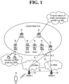
- a network configuration of FIG. 1 has been briefly reconfigured from the EPS higher level reference model.
- FIG. 1 shows the configuration of an evolved mobile communication network.
- FIG. 1 illustrates a Serving Gateway (S-GW) 52, a Packet Data Network Gateway (PDN GW) 53, a Mobility Management Entity (MME) 51, a Serving General Packet Radio Service (GPRS) Supporting Node (SGSN), and an enhanced Packet Data Gateway (ePDG) that correspond to some of the various elements.
- S-GW Serving Gateway
- PDN GW Packet Data Network Gateway
- MME Mobility Management Entity
- GPRS General Packet Radio Service
- SGSN Serving General Packet Radio Service
- ePDG enhanced Packet Data Gateway
- the S-GW 52 is an element that operates at a boundary point between a Radio Access Network (RAN) and a core network and has a function of maintaining a data path between an eNodeB 22 and the PDN GW 53. Furthermore, if a terminal (or User Equipment (UE) moves in a region in which service is provided by the eNodeB 22, the S-GW 52 plays a role of a local mobility anchor point. That is, for mobility within an E-UTRAN (i.e., a Universal Mobile Telecommunications System (Evolved-UMTS) Terrestrial Radio Access Network defined after 3GPP release-8), packets can be routed through the S-GW 52.
- E-UTRAN i.e., a Universal Mobile Telecommunications System (Evolved-UMTS) Terrestrial Radio Access Network defined after 3GPP release-8
- the S-GW 52 may play a role of an anchor point for mobility with another 3GPP network (i.e., a RAN defined prior to 3GPP release-8, for example, a UTRAN or Global System for Mobile communication (GSM) (GERAN)/Enhanced Data rates for Global Evolution (EDGE) Radio Access Network).
- a RAN defined prior to 3GPP release-8, for example, a UTRAN or Global System for Mobile communication (GSM) (GERAN)/Enhanced Data rates for Global Evolution (EDGE) Radio Access Network).
- GSM Global System for Mobile communication
- GERAN GERAN
- EDGE Enhanced Data rates for Global Evolution
- the PDN GW (or P-GW) 53 corresponds to the termination point of a data interface toward a packet data network.
- the PDN GW 53 can support policy enforcement features, packet filtering, charging support, etc.
- the PDN GW (or P-GW) 53 can play a role of an anchor point for mobility management with a 3GPP network and a non-3GPP network (e.g., an unreliable network, such as an Interworking Wireless Local Area Network (I-WLAN), a Code Division Multiple Access (CDMA) network, or a reliable network, such as WiMax).
- I-WLAN Interworking Wireless Local Area Network
- CDMA Code Division Multiple Access
- the S-GW 52 and the PDN GW 53 have been illustrated as being separate gateways, but the two gateways may be implemented in accordance with a single gateway configuration option.
- the MME 51 is an element for performing the access of a terminal to a network connection and signaling and control functions for supporting the allocation, tracking, paging, roaming, handover, etc. of network resources.
- the MME 51 controls control plane functions related to subscribers and session management.
- the MME 51 manages numerous eNodeBs 22 and performs conventional signaling for selecting a gateway for handover to another 2G/3G networks.
- the MME 51 performs functions, such as security procedures, terminal-to-network session handling, and idle terminal location management.
- the SGSN handles all packet data, such as a user's mobility management and authentication for different access 3GPP networks (e.g., a GPRS network and an UTRAN/GERAN).
- 3GPP networks e.g., a GPRS network and an UTRAN/GERAN.
- the ePDG plays a role of a security node for an unreliable non-3GPP network (e.g., an I-WLAN and a Wi-Fi hotspot).
- an unreliable non-3GPP network e.g., an I-WLAN and a Wi-Fi hotspot.
- a terminal having an IP capability can access an IP service network (e.g., IMS), provided by a service provider (i.e., an operator), via various elements within an EPC based on non-3GPP access as well as based on 3GPP access.
- IMS IP service network
- a service provider i.e., an operator
- FIG. 1 shows various reference points (e.g., S1-U and S1-MME).
- reference points e.g., S1-U and S1-MME.
- Table 1 defines reference points shown in FIG. 1 .
- various reference points may be present depending on a network configuration.
- REFERENCE POINT DESCRIPTION S1-MME A reference point for a control plane protocol between the E-UTRAN and the MME S1-U
- a reference point between the MME and the SGSN that provides the exchange of pieces of user and bearer information for mobility between 3GPP access networks in idle and/or activation state.
- This reference point can be used intra-PLMN or inter-PLMN (e.g. in the case of Inter-PLMN HO).
- S4 A reference point between the SGW and the SGSN that provides related control and mobility support between the 3GPP anchor functions of a GPRS core and the S-GW. Furthermore, if a direct tunnel is not established, the reference point provides user plane tunneling.
- S5 A reference point that provides user plane tunneling and tunnel management between the S-GW and the PDN GW. The reference point is used for S-GW relocation due to UE mobility and if the S-GW needs to connect to a non-collocated PDN GW for required PDN connectivity
- S11 A reference point between the MME and the S-GW SGi A reference point between the PDN GW and the PDN.
- the PDN may be a public or private PDN external to an operator or may be an intra-operator PDN, e.g., for the providing of IMS services. This reference point corresponds to Gi for 3GPP access.
- LTE long term evolution
- LTE-A LTE-Advanced
- 5th generation also known as 5G
- the 5G mobile communication defined in the international telecommunication union (ITU) provides a data transfer rate of up to 20Gbps and a sensible transfer rate of at least 100Mbps anytime anywhere.
- 'IMT-2020' is a formal name, and aims to be commercialized in the year 2020 worldwide.
- the ITU proposes three usage scenarios, e.g., eMBB(enhanced Mobile BroadBand), mMTC(massive Machine Type Communication), and URLLC(Ultra Reliable and Low Latency Communications).
- eMBB enhanced Mobile BroadBand
- mMTC massive Machine Type Communication
- URLLC Ultra Reliable and Low Latency Communications
- the URLLC relates to a usage scenario which requires a high reliability and a low latency.
- a service such as autonomous driving, factory automation, and augmented reality requires a high reliability and a low latency (e.g., a latency less than or equal to 1ms).
- a latency of 4G (LTE) is statistically 21-43ms (best 10%), 33-75ms (median). This is insufficient to support a service requiring the latency less than or equal to 1ms.
- an eMBB usage scenario relates to a usage scenario requiring a mobile ultra-wide band.
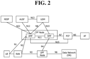
- FIG. 2 shows an example of an expected structure of next-generation mobile communication from a node perspective.
- a UE is coupled to a data network (DN) via a next generation radio access network (RAN).
- DN data network
- RAN next generation radio access network
- the illustrated control plane function (CPF) node performs the entirety or part of a mobility management entity (MME) function of 4G mobile communication and the entirety or part of a control plane function of an S-serving gateway (SG) and PDN gateway (P-GW).
- MME mobility management entity
- SG S-serving gateway
- P-GW PDN gateway
- the CPF node includes an access and mobility management function (AMF) and a session management function (SMF).
- AMF access and mobility management function
- SMF session management function
- the illustrated user plane function (UPF) node is a type of a gateway through which user data is transmitted/received.
- the UPF node may perform the entirety or part of a user plane function of an S-GW or P-GW of 4G mobile communication.
- PCF policy control function
- the illustrated application function is a server for providing several services to the UE.
- the illustrated unified data management is a type of a server which manages subscriber information, such as a home subscriber server (HSS) of 4G mobile communication.
- the UDM stores the subscriber information in a unified data repository (UDR) and manages it.
- UDR unified data repository
- the illustrated authentication server function (AUSF) authenticates and manages the UE.
- the illustrated network slice selection function (NSSF) is a node for network slicing as described below.
- the UE can simultaneously access two data networks by using multiple protocol data unit or packet data unit (PDU) sessions.
- PDU packet data unit
- FIG. 3 shows an example of an architecture for supporting simultaneous access to two data networks.
- a UE uses one PDU session to simultaneously access the two data networks.
- Next-generation mobile communication introduces the concept of network slicing in order to provide various services through a single network.
- slicing a network refers to a combination of network nodes with the functions needed to provide a specific service.
- the network node that constitutes the slice instance may be a hardware independent node, or it may be a logically independent node.
- Each slice instance may consist of a combination of all the nodes needed to construct the entire network. In this case, one slice instance alone may provide service to the UE.
- the slice instance may consist of a combination of some of the nodes that make up the network.
- the slice instance may provide service to the UE in association with other existing network nodes without the slice instacne alone providing the service to the UE.
- a plurality of slice instances may cooperate with each other to provide the service to the UE.
- the slice instance may differ from a dedicated core network in that all network nodes, including the core network (CN) node and the RAN may be separated from each other. Further, the slice instance differs from the dedicated core network in that the network nodes may be logically separated.
- CN core network
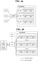
- FIG. 4A is an exemplary diagram illustrating an example of an architecture for implementing the concept of network slicing.
- the core network may be divided into several slice instances.
- Each slice instance may contain one or more of a CP function node and a UP function node.
- Each UE may use a network slice instance corresponign to its service through RAN.
- each slice instance may share one or more of a CP function node, and a UP function node with another slice instance. This will be described with reference to FIG. 4B below.
- FIG. 4B is an exemplary view showing another example of an architecture for implementing the concept of network slicing.
- a plurality of UP function nodes are clustered, and a plurality of CP function nodes are also clustered.
- slice instance # 1 (or instance # 1) in the core network includes a first cluster of an UP function node. Moreover, the slice instance # 1 shares the cluster of the CP function node with slice instance # 2 (or instance # 2). The slice instance # 2 includes a second cluster of an UP function node.
- the illustrated NSSF selects a slice (or instance) that can accommodate the UE's service.
- the illustrated UE may use the service # 1 via the slice instance # 1 selected by the NSSF and may use the service # 2 via the slice instance # 2 selected by the NSSF.
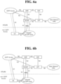
- a method for processing a signaling request from a UE while the UE roams to a visit network for example, a visited public land mobile network (VPLMN).
- the first method is a local break out (LBO) method in which the signaling request from the UE is processed at the network.
- the second method is a home routing (HR) method in which the visit network transmit the signaling request from the UE to a home network of the UE.
- LBO local break out
- HR home routing
- FIG. 5A is a diagram illustrating an example of architecture to which the LBO method is applied during roaming
- FIG. 5B is a diagram illustrating an example of architecture to which the HR method is applied during roaming.
- a PCF in the VPLMN performs an interaction with an AF to create a PCC rule for a service in the VPLMN.
- a PCF node in the VPLMN creates the PCC rule based on a policy that is set according to a roaming agreement with a home public land mobile network (HPLMN) operator.
- HPLMN home public land mobile network
- the data of the UE is transmitted to the data network in the HPLMN.
- next-generation mobile communication data of a UE may be offloaded to a non-3GPP network, for example, a wireless local area network (WLAN) or a Wi-Fi.
- WLAN wireless local area network
- Wi-Fi Wireless Fidelity
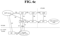
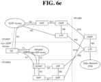
- FIGS. 6A to 6F illustrate architectures for offloading data to the non-3GPP network.
- a WLAN or a Wi-Fi is regarded as an untrusted non-3GPP network.
- a non-3GPP interworking function N3IWF may be added.
- a PDU session may be established through a 3GPP access and a non-3GPP access.
- a multi-access (MA) PDU session by bundling two separate PDU sessions established through the different accesses has been proposed.
- a disclosure of the present specification provides a method according to claim 1.
- the method may further include generating context of a PDU session based on the information indicating the MA PDU session.
- the context of the PDU session may include an access type.
- the access type may indicate both the first access and the second access.
- the PDU session establishment request message may include session network slice selection assistance information (S-NSSAI), and the delivering of the PDU session establishment request message may include delivering allowed NSSAI for each access.
- S-NSSAI session network slice selection assistance information
- the method may further include: identifying S-NSSAI of the MA PDU session is comprised in allowed NSSAI for corresponding access when the UE is registered through only any one of the first access and the second access and when the UE is registered through another access; and transmitting a request for release of the MA PDU session to the SMF node when the S-NSSAI of the MA PDU session is comprised in the allowed NSSAI for the corresponding access.
- the method may further include: receiving a registration request message comprising a list of a PDU session to be activated from the UE when the UE is not registered over the second access; and delivering necessity of activating the MA PDU session to the SMF node based on the list.
- the method may further include: receiving a request for notification from the SMF node in occurrence of a first event in which the UE is registered through the second access or in occurrence of a second event of a switch to a connected state occurs when user plane setup for the MA PDU session is performed first through only the first access; and transmitting a notification to the SMF node when the first event or second event occurs.
- the first access may be 3rd Generation Partnership Project (3GPP) access and the second access may be non-3GPP access, or the first access may be non-3GPP access and the second access may be 3GPP access.
- 3GPP 3rd Generation Partnership Project
- a disclosure of the present specification provides a method according to claim 8.
- the receiving of the PDU session establishment request message may include receiving one or more of session network slice selection assistance information (S-NSSAI) and allowed NSSAI for each access.
- S-NSSAI session network slice selection assistance information
- the method may further include: transmitting a request for notification to the AMF node in occurrence of a first event in which the LTE is registered through the second access or in occurrence of a second event of a switch to a connected state occurs when user plane setup for the MA PDU session is performed first through only the first access; and receiving a notification from the AMF node when the first event or second event occurs.
- the generating of the MA PDU session may include: performing user plane setup for the first access; and performing user plane setup for the second access.
- the PDU session establishment acceptance message may include information indicating access for which user plane setup is performed among the first access and the second access.
- the method may further include: performing user plane setup for the second access when the LTE is registered over the second access in a case where the MA PDU session is generated through only the first access in the generating of the MA PDU session.
- the method may further include: transmitting a request for notification to the AMF node in occurrence of a first event in which the UE is registered through the second access or in occurrence of a second event of a switch to a connected state occurs in a case where the MA PDU session is generated through only the first access in the generating of the MA PDU session.
- a disclosure of the present specification provides an access and mobility management function (AMF) node according to claim 12.
- AMF access and mobility management function
- a disclosure of the present specification provides a session management function (SMF) node according to claim 13.
- SMS session management function
- the term 'include' or 'have' may represent the existence of a feature, a number, a step, an operation, a component, a part or the combination thereof described in the specification, and may not exclude the existence or addition of another feature, another number, another step, another operation, another component, another part or the combination thereof.
- first' and 'second' are used for the purpose of explanation about various components, and the components are not limited to the terms 'first' and 'second'.
- the terms 'first' and 'second' are only used to distinguish one component from another component.
- a first component may be named as a second component without deviating from the scope of the present disclosure.
- UEs user equipments
- the UE may also be denoted a terminal or mobile equipment (ME).
- ME mobile equipment
- the UE may be a laptop computer, a mobile phone, a PDA, a smartphone, a multimedia device, or other portable device, or may be a stationary device such as a PC or a car mounted device.
- UE/MS is an abbreviation of User Equipment/Mobile Station, and it refers to a terminal device.
- An EPS is an abbreviation of an Evolved Packet System, and it refers to a core network supporting a Long Term Evolution (LTE) network and to a network evolved from an UMTS.
- LTE Long Term Evolution
- a PDN is an abbreviation of a Public Data Network, and it refers to an independent network where a service for providing service is placed.
- a PDN connection refers to a connection from UE to a PDN, that is, an association (or connection) between UE represented by an IP address and a PDN represented by an APN.
- a Serving gateway is a network node of an EPS network which performs functions, such as mobility anchor, packet routing, idle mode packet buffering, and triggering an MME to page UE.
- An eNodeB is an eNodeB of an Evolved Packet System (EPS) and is installed outdoors.
- the cell coverage of the eNodeB corresponds to a macro cell.
- EPS Evolved Packet System
- An MME is an abbreviation of a Mobility Management Entity, and it functions to control each entity within an EPS in order to provide a session and mobility for UE.
- a session is a passage for data transmission, and a unit thereof may be a PDN, a bearer, or an IP flow unit.
- the units may be classified into a unit of the entire target network (i.e., an APN or PDN unit) as defined in 3GPP, a unit (i.e., a bearer unit) classified based on QoS within the entire target network, and a destination IP address unit.
- An Access Point Name is the name of an access point that is managed in a network and provides to UE. That is, an APN is a character string that denotes or identifies a PDN. Requested service or a network (PDN) is accessed via P-GW.
- An APN is a name (a character string, e.g., 'internet.mnc012.mcc345.gprs') previously defined within a network so that the P-GW can be searched for.
- a PDN connection is a connection from UE to a PDN, that is, an association (or connection) between UE represented by an IP address and a PDN represented by an APN. It means a connection between entities (i.e., UE-PDN GW) within a core network so that a session can be formed.
- entities i.e., UE-PDN GW
- UE context is information about the situation of UE which is used to manage the UE in a network, that is, situation information including an UE ID, mobility (e.g., a current location), and the attributes of a session (e.g., QoS and priority)
- situation information including an UE ID, mobility (e.g., a current location), and the attributes of a session (e.g., QoS and priority)
- NAS Non-Access-Stratum: A higher stratum of a control plane between a UE and an MME.
- the NAS supports mobility management, session management, IP address management, etc., between the UE and the network.
- PLMN as an abbreviation of Public Land Mobile Network, means a network identification number of a mobile communication provider.
- the PLMN is classified into a home PLMN (HPLMN) and a visited PLMN (VPLMN).
- HPLMN home PLMN
- VPLMN visited PLMN
- DNN as an abbreviation of a data network name, means an access point for management in a network, similarly to an APN, and is provided to a UE. In the 5G system, the DNN is used equivalently as the APN.
- NSSP Network Slice Selection Policy: used by a UE for mapping an application and Session Network Slice Selection Assistance Information (S-NSSAI)
- a new mobile communication network provides various modes to support session and service continuity (SSC).
- SSC session and service continuity
- a UPF operating as a PDU session anchor is maintained regardless of an access technology (that is, an access type and a cell).
- IP continuity is maintained regardless of movement of a UE.
- SSC Mode 1 may be applied to any PDU session type and also applied to any access type.
- a network may trigger release of the PDU session and instruct a UE to establish the same PDU session.
- a UE operating as the PDU session anchor may be newly selected.
- SSC Mode 2 may be applied to any PDU session type and also applied to any access type.
- a network may allow connectivity establishment of a UE using a new PDU session with respect to the same data network. If a trigger condition is applied, the network may determine whether to select an appropriate PDU session anchor for the new condition, that is, a UPF. SSC Mode 3 may be applied to any PDU session type and also applied to any access type.
- an SSC mode selection policy may be used.
- An operator may provide the UE with the SSC mode selection policy.
- the policy may include one or more SSC mode selection policy rules.
- FIG. 7 illustrates the state of a PDU session.
- FIG. 7 shows a PDU session active state, a PDU session inactive state, a PUD session inactivation pending state, a PDU session activation pending state, and a PDU session modification pending state.
- the PDU session inactive state refers to a state in which no PDU session context exists.
- the PDU session activation pending state refers to a state in which a UE is waiting for a response from a network after initiating a PDU session establishment procedure to the network.
- the PDU session active state refers to a state in which PDU session context is active in a UE.
- the PDU session inactivation pending state refers to a state in which a UE is waiting for a response from a network after initiating a PDU session release procedure.
- the PDU session modification pending state refers to a state in which a UE is waiting for a response from a network after initiating a PDU session modification procedure.
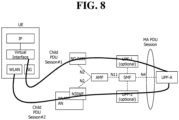
- an MA PDU session may be generated by bundling two separate PDU sessions established over different accesses.
- FIG. 8 shows an example in which an MA PDU session is generated according to a conventional art.
- An MA PDU session includes at least two PDU sessions, referred to as child PDU sessions as shown in FIG. 8 .
- One of the two PDU sessions is established over 3GPP access, and the other PDU session is established over untrusted non-3GPP access (e.g., WLAN AN).
- untrusted non-3GPP access e.g., WLAN AN
- the MA PDU session enables a multi-path data link between a UE and an UPF-A.
- the MA PDU session may operate below an IP layer.
- the MA PDU session may be established through one of the following procedures.
- the child PDU sessions may have the same IP address.
- Session Management (SM) signaling related to the MA PDU session may be transmitted and received through random access.
- SM Session Management
- the two child PDU sessions may be established through two separate PDU session establishment procedures. For example, the UE may establish a first PDU session over 3GPP access and may then establish a second PDU session over non-3GPP access. The two PDU sessions may be linked to each other and may become child PDU sessions of an MA PDU session.
- a linked PDU session may be provided to a 5G Core Network (5GC).
- the 5GC links the second PDU session with the linked PDU session and designates the two PDU sessions as child PDU sessions of an MA PDU session.
- the UE Since the linked PDU session is provided to the 5GC, the UE does not need to request specific values for a DNN, an S-NSSAI, an SSC mode, a PDU type, and the like.
- the second PDU session may inherit all these values from the linked PDU session.
- a request type in an establishment request message for establishment of the second PDU session may be set to "initial request".
- the 5GC interprets the message as a request for establishing an MA PDU session and links the requested PDU session to the existing "linked” PDU session.
- a new Request Type may be specified.
- the two child PDU sessions may be established in parallel through a single procedure.
- This single procedure may be referred to as a UE-requested MA PDU session establishment procedure.
- This procedure may be useful when the UE intends to establish an MA PDU session while already registered in the 5GC via both accesses. Instead of initiating two separate PDU session establishment procedures, the UE may initiate one MA PDU establishment procedure, thereby establishing two child PDU sessions.
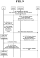
- FIG. 9 shows an example of a procedure for combined establishment of an MA PDU session according to a conventional art.
- the combined establishment procedure illustrated in FIG. 9 shows a UE-requested MA PDU session establishment procedure.
- Two child PDU session establishment procedures have different PDU session IDs.
- a child PDU session over 3GPP access is indicated by PDU session ID-1
- a child PDU session over non-3GPP access is indicated by PDU session ID-2.
- An SMF of a 5GC triggers two N2 PDU session establishment procedures.
- a UE may receive a PDU session establishment acceptance message for PDU session ID-1 over 3GPP access and may receive a PDU session establishment acceptance message for PDU session ID-2 over non-3GPP access.
- the SMF may anchor both PDU sessions to the same UPF and may allocate the same IP address to both PDU sessions.
- the foregoing combined MA PDU session establishment procedure is a method of bundling PDU sessions over different accesses into an MA PDU session and managing the MA PDU session.
- a UE and a network need to separately manage context for a PDU session over each access and context for managing the two PDU sessions together, thus complicating maintenance of the sessions. It is assumed that the UE is registered over 3GPP access and non-3GPP access.
- a method for handling this case has not been studied so far.
- a method for managing the MA PDU session has not been studied so far.
- an aspect of disclosures of this specification is to provide methods for an SMF to efficiently manage an MA PDU session.
- an MA PDU session is a PDU session generated with one PDU session stretching across both 3GPP access and non-3GPP access. Accordingly, a UE can use 3GPP access and non-3GPP access in parallel with only one PDU session.
- a PDU session may be referred to as being active when user-plane (UP) resources are allocated, and may be referred to as being inactive when there is no user-plane (UP) resource.
- UP user-plane
- UP user-plane
- UP user-plane
- UP user-plane
- the MA PDU may be defined as being in a new state or as being in an active state.
- the MA PDU session is defined as being in a new state, for example, a partially active state.
- FIG. 10 illustrates states for managing an MA PDU session.
- an MA PDU session may be in any one of three states, which are an active state, an active state, and a partially active state.
- the MA PDU session may have these states in all of a UE, an SMF, and a PCF.
- UP user plane
- the MA PPD session may be considered active, and information about enabled access and disabled access may be additionally stored.
- FIG. 11 is a flowchart illustrating an improved procedure for combined establishment of an MA PDU session according to a disclosure of the present specification.
- a UE assumes that both 3GPP access and non-3GPP access are registered in the same PLMN.
- the AMF may also transmit allowed NSSAI for each access to the SMF.
- the AMF may forward, to the SMF, information about whether S-NSSAI forwarded by the UE along with the PDU session establishment request is included in allowed NSSAI for both accesses.
- the SMF may accept the MA PDU establishment request only when the allowed NSSAI for both accesses includes the S-NSSAI forwarded by the UE based on the information.
- the AMF may directly determine to reject the request from the UE only when the S-NSSAI forwarded by the UE is not included in the allowed NSSAI for both accesses.
- the AMF identifies whether the S-NSSAI of the MA PDU session is included in allowed NSSAI for the other access.
- the AMF may request the SMF to release the MA PDU session. In this case, the AMF may forward a cause value or indication indicating that the allowed NSSAI is not allowed for both accesses.
- the SMF may perform a procedure for releasing the MA PDU session or changing the MA PDU session to a normal PDU session (single-access PDU session) used only via access for which the S-NSSAI is allowed.
- the SMF may perform a PDU session modification or PDU session release procedure.
- the SMF transmits, to the UE, a PDU session modification command/PDU session release command message including a cause value or indication indicating that the MA PDU session has been changed to the normal PDU session and indicates access over which the PDU session is allocated to the UE.
- the SMF may indicate to the AMF that the MA PDU session has been changed to the normal PDU session using a Namf_PDU session_SMContextStatusNotify service or a different service. Further, the SMF may forward an access type indicating access through which the PDU session is generated. Upon receiving the access type, the AMF may update the access type of the MA PDU session based on both of the two accesses or the access type (3GPP access or non-3GPP access) indicated by the SMF.
- This operation may be performed for different reasons, e.g., when the UE has been registered over one access to generate an MA PDU session but is registered through a different PLMN over the other access, when S-NSSAI of an MA PDU session has been included in the allowed NSSAI for both accesses but S-NSSAI of the MA PDU session over one access is excluded from the allowed NSSAI due to mobility of the UE, when subscription information of the UE is updated (which is triggered by the SMF), or when a policy is updated by an operator or PCF and thus does not allow the MA PDU session any more.
- the SMF performs combined session establishment based on the MA indication and the combined session establishment indication transmitted by the UE.
- the SMF performs a combined session establishment procedure only when the UE is registered over both accesses according to the information transmitted by the AMF.
- the SMF transmits an N2 SM message over access (e.g., 3GPP access) signaled by the UE and the other access (e.g., non-3GPP access), thereby allocating a user-plane resource (i.e., N3 resource).
- the SMF may determine, based on the operator's policy, whether to first transmit the N2 SM message over one access or to simultaneously transmit the N2 SM message over both accesses in order to perform the procedure for allocating the user-plane resource.
- a PDU session acceptance message transmitted to the UE includes a QoS rule, and assuming that the QoS rule is available for both accesses, it is desirable to transmit the QoS rule to the UE after a QoS is set up for both accesses. Further, since transmissions of the N2 SM message and an NAS PDU session acceptance message are generally performed together by one N1N2MessageTransfer, a user plane may be set up over the opposite access and a QoS rule may be determined based on the user plane actually set up.
- the UE when allocating user-plane resources over both accesses in parallel, the UE cannot identify access over which a user-plane resource is being allocated after receiving the PDU session establishment acceptance message and may thus autonomously perform a subsequent operation for allocating a user-plane resource (e.g., a PDU session establishment request or service request). In this case, the UE may transmit an unnecessary signal even though a user-plane resource allocation procedure is in progress in a network. To prevent this situation, the SMF may indicate access (e.g., both accesses, only 3GPP access, or only non-3GPP access) over which a user-plane resource is successfully allocated through an indication in the PDU session establishment acceptance message.
- access e.g., both accesses, only 3GPP access, or only non-3GPP access
- the SMF may indicate the reason why the user-plane resource is allocated over only one access to the UE through a cause value or the like. For example, a user-plane resource may not be allocated because there is congestion in one access or when an MM procedure, such as a registration/service request, is in progress. Accordingly, the SMF first needs to perform a user-plane resource allocation procedure over access other than access for which the UE transmits a request message. The UE may determine when to request user-plane resource allocation over the other access based on the indication and the cause value received through the acceptance message.
- the SMF may perform a combined session establishment procedure.
- the SMF transmits the N2 SM message only over the access over which the UE is registered, thereby allocating a user-plane resource.
- the SMF After the user-plane resource is successfully set up according to the foregoing processes 5-10, the SMF performs a process for allocating a user-plane resource through the access signaled by the UE. Here, the SMF also indicates to the UE that the MA PDU session has been successfully generated.
- the SMF When the SMF fails to generate the user-plane resource over the access according to the foregoing processes 5-10 or when the UE is not registered over one access and thus the SMF does not attempt to generate a user-plane resource over access, the SMF manages the state of the MA PDU session as illustrated in FIG. 10 . Further, in this case, the SMF indicates that the MA PDU session is successfully generated by transmitting a PDU session establishment acceptance message to the UE and indicates the access over which the user-plane resource is completely allocated (or indicates access over which no user-plane resource is allocated). Upon receiving the PDU session establishment acceptance message, the UE manages the state of the MA PDU session as illustrated in FIG. 10 .
- the PDU session establishment acceptance message may enable the UE to recognize that the UE is not registered over the access over which no user-plane resource is allocated through separate or implicit information.
- the SMF may transmit a PDU session acceptance message to the UE without any additional indication or cause value when accepting the request.
- the UE may recognize that the request for the MA PDU session has been successful. Further, when recognizing that a user plane has been set up over only one access, the UE manages the state of the MA PDU session as illustrated in FIG. 10 .
- the SMF may transmit a PDU session acceptance message and may indicate that the MA PDU session is a normal PDU session rather than an MA PDU session through a cause value or indication.
- the SMF may transmit an indication only when the MA PDU session is allowed, and may not include an indication when the MA PDU session is allowed as a normal PDU session, thereby indicating the usage of the generated PDU session.
- the SMF may also indicate access over which the PDU session has been generated. When there is no separate access information, the UE may recognize that a normal PDU session has been generated through access over which the acceptance message has been received.
- a user-plane resource cannot be allocated over specific access for the following reasons.
- the SMF may perform a session management policy establishment procedure with the PCF.
- the SMF may provide information indicating that the generated PDU session is an MA PDU session and state information about the PDU session (the states illustrated in FIG. 10 and/or the enabled/disabled state of each access) to the PCF.
- the PCF may configure the traffic steering rule such that traffic is not routed over disabled access or disabled access has a lower priority than enabled access when selected as access over which traffic is routed.
- the UE may configure the traffic steering rule such that traffic is not routed over disabled access or disabled access has a lower priority than enabled access when selected as access over which traffic is routed.
- the SMF may transmit an indication or may update the traffic steering rule so as not to perform traffic steering over the access.
- the UPF may not know access over which a user plane is set up.
- the SMF can release only a connection between the AN node and the additional UPF.
- the SMF may not release a connection between the additional UPF and the PSA.
- the PSA performing ATSSS does not recognize whether a user plane is set up. Therefore, the SMF needs to directly indicate corresponding information to the PSA.
- the SMF may also always release the additional UPF when releasing a user plane over specific access.
- the additional UPF need to be configured between the AN node and the PSA when setting up the user plane, more signaling may occur.
- the UE may request user plane allocation through a registration/service request over the access.
- the AMF may report the registration of the UE to the SMF, and the SMF may allocate a user-plane resource for the access.
- the SMF may request a notification service of reporting an event from the AMF when the UE is registered or is connected over access in which a user plane resource is not allocated while generating a PDU session.
- the AMF reports to the SMF that the UE is registered or is connected based on the notification service requested by the SMF.
- the UE When the UE performs registration or performs a service request procedure, the UE may forward information indicating that the UE wants to activate the MA PDU session. Accordingly, the AMF may report to the SMF serving the PDU session that the PDU session needs to be activated over access which has been released or over which a service request has been performed. Subsequently, the SMF performs an operation of allocating a user-plane resource for the access.
- the UE may use a list of PDU sessions to be activated in order to request activation of the MA PDU session.
- the AMF may request activation of the PDU session from the SMF based on the list.
- it is possible to activate only a PDU session for corresponding access That is, when a service request message is transmitted through 3GPP access, it is possible to request activation of only a PDU session for 3GPP access.
- a service request message is transmitted through non-3GPP access, it is possible to request activation of only a PDU session for non-3GPP access.
- the SMF when receiving a request for activation of a user plane from the AMF, the SMF can set up user planes for both accesses.
- the SMF can set up a user plane only for access over which the UE is registered based on registration information from the AMF.
- the AMF may report setup of a user plane and may also report information about access for which the user plane is set up. That is, when the UE is registered over only one access, the AMF may forward access information to the access, thereby requesting setup of a user plane for the access.
- the AMF may forward both accesses or multiple accesses, thereby requesting setup of user planes for both accesses.
- the SMF sets up a user plane only for access for which a user plane is not set up based on the information forwarded by the AMF.
- the UE may use the list of PDU sessions to be activated.
- the list of PDU sessions to be activated is included only in mobility registration or periodic registration.
- the UE may request PDU session activation for the MA PDU at the same time as performing initial registration over non-3GPP access.
- the AMF may forward the PDU session activation request for the MA PDU to the SMF only when the registration is successful.
- the list of PDU sessions to be activated may be used to request allocation of a user-plane resource only for corresponding access rather than being used to request allocation of all user-plane resources for both accesses as in the above operation.
- the SMF allocates a user-plane resource only for access requested by the UE based on the list of PDU sessions to be activated.
- a new indication may be added to request allocation of all user-plane resources for both accesses.
- the UE determines which indication to use according to desired access for which a user-plane resource is allocated. Accordingly, when traffic needs to be transmitted over only one access, it is not necessary to allocate resources for both accesses, thus efficiently using resources (e.g., GBR QoS flow).
- the SMF When the SMF successfully allocates a user-plane resource for disabled access, the disabled access is switched to the enabled state.
- the state of the MA PDU session When the state of the MA PDU session is managed as the partially active state, the state of the MA PDU session is updated to the active state.
- the SMF may perform a session management policy modification operation with the PCF.
- the PCF When the PCF performs an operation of generating a traffic steering rule for the MA PDU session, the PCF may configure the traffic steering rule such that traffic is routed over enabled access or enabled access has a higher priority than access that was originally enabled when selected as access over which traffic is routed.
- the traffic steering rule may be generated for the MA PDU session such that traffic is routed over access when a user plane is activated for the access that was disabled. Alternatively, the traffic steering rule may configure a priority such that access over which traffic is routed is preferentially selected.
- the SMF may transmit an indication or may update the traffic steering rule so as not to perform traffic steering over the access.
- the UE When the UE is registered over both 3GPP and non-3GPP, the UE transmits the PDU session establishment request message is transmitted through 3GPP access. Otherwise, when the UE is idle over 3GPP access, the AMF may need to transmit a paging signal to the UE in order to set up a user plane. Therefore, in order to reduce use of resources for the paging signal, the UE may transmit a PDU session establishment request over 3GPP access. When the UE is idle over 3GPP access, the UE may first perform a service request procedure and may then transmit the PDU session establishment request.
- the AMF transmits a release request message to the SMF in order to release a PDU session generated through access from which deregistration needs to be performed.
- the AMF reports to the SMF managing the MA PDU session that deregistration from the specific access has occurred.
- the SMF may perform one of the following operations based on an operator policy, a reason for the deregistration, and the like.
- the UE also manages the PDU session by changing the state of the PDU session in response to the operation performed by the SMF.
- the UE may perform the above operations i) and ii) according to the changed state of the PDU session.
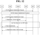
- FIG. 12 illustrates a procedure in which a UE initiates setup of a user plane according to a disclosure of the present specification.
- FIG. 12 shows a procedure in which a UE initiates setup of a user plane for non-3GPP access when an MA PDU session is generated in a state of being registered over only 3GPP access or being deregistered from non-3GPP access/idle over non-3GPP access.
- the UE may determine that the MA PDU session has been established but the user plane has been set up over only one access based on some or a combination of a plurality of the following conditions.
- the UE performs a registration procedure or a service request procedure through non-3GPP.
- the UE may request activation of the MA PDU session by including a list of PDU sessions to be activated in a registration/service request message.
- an AMF reports the request to the SMF.
- the SMF performs a user plane setup procedure for non-3GPP access according to the requests received from the UE and the AMF.
- the UE and an N3IWF generate an IPsec tunnel for the MA PDU through non-3GPP access, and accordingly the UE may recognize that the MA PDU session is successfully activated.
- the UE receives a service acceptance message or a registration acceptance message.
- the UE may recognize that the user plane has been successfully set up based on a PDU session reactivation result included in the received message.
- the user plane can be set up in the service request procedure/registration procedure, it is possible to quickly set up the user plane.
- the UE needs to actively request user plane setup.
- FIG. 13 illustrates a procedure in which a network initiates setup of a user plane according to a disclosure of the present specification.
- FIG. 13 shows a procedure in which a UE initiates setup of a user plane for non-3GPP access when an MA PDU session is generated in a state of being registered over only 3GPP access or being deregistered from non-3GPP access/idle over non-3GPP access.
- the AMF needs to make a notification request to the SMF and sets up a user plane according to a detected event after a registration procedure/service request procedure is over, thus complicating the procedure and slightly retarding a procedure of setting up the user plane.
- the UE-initiated procedure illustrated in FIG. 12 and the network-initiated procedure illustrated in FIG. 13 may be used in combination.
- a list of PDU sessions to be activated is conventionally transmitted when there is data to be transmitted. Therefore, when there is no data to be transmitted, the UE may not configure and transmit a list of PDU sessions to be activated.
- a network may transmit data over only one access in an MA PDU.
- the SMF requests a notification of an event from the AMF, and thus the network-initiated procedure may be used together. That is, when there is user-plane data to be transmitted, the UE configures and transmits a list of PDU sessions to be activated according to the UE-initiated procedure, and the AMF reports to the SMF that the MA PDU session is included in the list if the MA PDU session is included in the list, thereby setting up a user plane. Further, the AMF reports that the UE is registered or connected according to the event of which a notification is requested by the SMF.
- the SMF may set up a user plane according to the network-initiated procedure. Alternatively, the SMF may recognize that the UE is connected, and may set up a user plane when there is actual downlink data.
- the second disclosure illustrates an improvement in 3GPP standard technology based on the methods according to the first disclosure.
- FIG. 14 is a flowchart illustrating a PDU session establishment process in a non-roaming case and an LBO roaming case.
- the AMF determines the access type of access over which the message is received.
- the AMF may include the MA PDU request indication and RM state information of each access in a Nsmf_PDUSession_CreateSMContext request message.
- the SMF selects a PCF supporting the ATSSS function.
- the SMF may accept the PDU session establishment request based on the AMF capability, an operator policy and subscription information obtained from a UDM.
- the SMF When dynamic PCC is deployed and both the AMF and the SMF support an MA PDU session, the SMF transmits an MA PDU request indication and associated access information to the PCF via the SM policy control create message.
- the PCF determines whether the MA PDU session is allowed based on the operator policy and the subscription information.
- the PCF provides PCC rules related with the MA PDU session during a policy association establishment procedure.
- the SMF derives ATSSS rules, which will be transmitted to the UE to control traffic steering, and N4 rules.
- the SMF selects an UPF supporting ATSSS capability and MPTCP capability.
- the SMF initiates user-plane resource setup over the second access (e.g. non-3GPP access) different from first access (e.g., 3GPP access) over which the PDU session establishment request is received.
- second access e.g. non-3GPP access
- first access e.g., 3GPP access
- the SMF may include an access type indicating the second access in a Namf_Communication_N1N2MessageTransfer message.
- the SMF initiates user-plane resource setup over the first access over which the PDU session establishment request is received.
- the SMF may include an access type indicating the first access in the Namf_Communication_N1N2MessageTransfer message.
- the SMF may forward an N1 SM container (PDU session establishment acceptance message) having an ATSSS capability and/or MPTCP function indication and the ATSSS rules.
- N1 SM container PDU session establishment acceptance message
- the SMF When the PDU session establishment request message received by the SMF includes information about the ATSSS capability and the MPTCP capability and the SMF determines to activate only one access PDU session, the SMF notifies associated access of the PDU session. Then, the AMF may update information about the access type of the PDU session.
- FIG. 15 is a block diagram illustrating the configuration of a UE and a network node according to an embodiment of the present disclosure .
- the UE 100 includes a storage unit 101, a controller 102, and a transceiver 103.
- the network node may be any one of an AMF, an SMF, an NEF, and an AF.
- the network node includes a storage unit 511, a controller 512, and a transceiver 513.
- the storage units store the foregoing methods.
- the controllers control the storage units and the transceivers. Specifically, the controllers execute the methods stored in the storage units, respectively. The controllers transmit the foregoing signals through the transceivers.
Landscapes
- Engineering & Computer Science (AREA)
- Computer Networks & Wireless Communication (AREA)
- Signal Processing (AREA)
- Computer Security & Cryptography (AREA)
- Databases & Information Systems (AREA)
- Mobile Radio Communication Systems (AREA)
Claims (13)
- Verfahren zum Verarbeiten einer Sitzungseinrichtung einer Protokolldateneinheit (PDU-Sitzungseinrichtung) durch einen Knoten mit Zugriffs- und Mobilitätsverwaltungsfunktion (AMF-Knoten), wobei das Verfahren Folgendes umfasst:Empfangen einer Anforderungsnachricht für eine PDU-Sitzungseinrichtung von einem Benutzergerät (UE) (100) über einen ersten Zugriff oder einen zweiten Zugriff, wobei die Anforderungsnachricht für eine PDU-Sitzungseinrichtung die Informationen umfasst, die eine Mehrfachzugriffs-PDU-Sitzung (MA-PDU-Sitzung) angeben;Auswählen eines Knotens mit Sitzungsverwaltungsfunktion (SMF-Knoten), der eine MA-PDU-Sitzung unterstützt, basierend auf den Informationen, die die MA-PDU-Sitzung angeben; undZustellen der Anforderungsnachricht für eine PDU-Sitzungseinrichtung an den SMF-Knoten, der die MA-PDU-Sitzung unterstützt,wobei das Zustellen der Anforderungsnachricht für eine PDU-Sitzungseinrichtung das Weiterleiten von i) Informationen, die angeben, ob das UE (100) sowohl über den ersten Zugriff als auch über den zweiten Zugriff registriert ist oder nur über einen davon registriert ist, und/oder ii) Informationen, die angeben, ob das UE (100) sich in einem Ruhezustand oder einem verbundenen Zustand befindet, umfasst.
- Verfahren nach Anspruch 1, ferner umfassend:Erzeugen des Kontexts einer PDU-Sitzung basierend auf den Informationen, die die MA-PDU-Sitzung angeben,wobei der Kontext der PDU-Sitzung einen Zugriffstyp umfasst, undder Zugriffstyp sowohl den ersten Zugriff als auch den zweiten Zugriff angibt.
- Verfahren nach Anspruch 1, wobei die Anforderungsnachricht für eine PDU-Sitzungseinrichtung S-NSSAI (Session Network Slice Selection Assistance Information) umfasst und das Zustellen der Anforderungsnachricht für eine PDU-Sitzungseinrichtung das Zustellen zulässiger NSSAI für jeden Zugriff umfasst.
- Verfahren nach Anspruch 1, ferner umfassend:das Identifizieren von S-NSSAI der MA-PDU-Sitzung ist in den zulässigen NSSAI für den entsprechenden Zugriff enthalten, wenn das UE nur über den ersten Zugriff oder den zweiten Zugriff registriert ist und wenn das UE über einen anderen Zugriff registriert ist; unddas Übertragen einer Anforderung zur Freigabe der MA-PDU-Sitzung an den SMF-Knoten, wenn die S-NSSAI der MA-PDU-Sitzung in den zulässigen NSSAI für den entsprechenden Zugriff enthalten sind.
- Verfahren nach Anspruch 1, ferner umfassend:Empfangen einer Registrierungsanforderungsnachricht, die eine Liste einer zu aktivierenden PDU-Sitzung umfasst, vom UE (100), wenn das UE (100) nicht über den zweiten Zugriff registriert ist; undZustellen der Notwendigkeit des Aktivierens der MA-PDU-Sitzung basierend auf der Liste an den SMF-Knoten.
- Verfahren nach Anspruch 1, ferner umfassend:Empfangen einer Anforderung zur Benachrichtigung vom SMF-Knoten beim Auftreten eines ersten Ereignisses, bei dem das UE (100) durch den zweiten Zugriff registriert ist, oder beim Auftreten eines zweiten Ereignisses eines Wechsels in einen verbundenen Zustand, wenn eine Einrichtung auf Benutzerebene für die MA-PDU-Sitzung zunächst nur durch den ersten Zugriff durchgeführt wird; undÜbertragen einer Benachrichtigung an den SMF-Knoten, wenn das erste Ereignis oder das zweite Ereignis auftritt.
- Verfahren nach Anspruch 1, wobei der erste Zugriff ein 3rd Generation Partnership Project-Zugriff (3GPP-Zugriff) ist und der zweite Zugang kein 3GPP-Zugriff ist, oder
der erste Zugriff kein 3GPP-Zugriff ist und der zweite Zugriff ein 3GPP-Zugriff ist. - Verfahren zum Verarbeiten einer Sitzungseinrichtung einer Protokolldateneinheit (PDU-Sitzungseinrichtung) durch einen Knoten mit Sitzungsverwaltungsfunktion (SMF-Knoten), wobei das Verfahren Folgendes umfasst:Empfangen, von einem Knoten mit Zugriffs- und Mobilitätsverwaltungsfunktion (AMF-Knoten), einer Anforderungsnachricht für eine PDU-Sitzungseinrichtung von einem Benutzergerät (UE) (100), wobei die Anforderungsnachricht für eine PDU-Sitzungseinrichtung die Informationen umfasst, die eine Mehrfachzugriffs-PDU-Sitzung (MA-PDU-Sitzung) einschließlich eines ersten Zugriffs und eines zweiten Zugriffs angeben;Erzeugen einer MA-PDU-Sitzung durch den ersten Zugriff oder den zweiten Zugriff oder durch beide basierend auf den Informationen, die die MA-PDU-Sitzung angeben; undZustellen einer Annahmenachricht für eine PDU-Sitzungseinrichtung,wobei das Empfangen der Anforderungsnachricht für eine PDU-Sitzungseinrichtung das Empfangen von i) Informationen, die angeben, ob das UE (100) sowohl über den ersten Zugriff als auch über den zweiten Zugriff registriert ist oder nur über einen davon registriert ist, und/oder ii) Informationen, die angeben, ob das UE (100) sich in einem Ruhezustand oder einem verbundenen Zustand befindet, umfasst.
- Verfahren nach Anspruch 8, wobei das Empfangen der Anforderungsnachricht für eine PDU-Sitzungseinrichtung das Empfangen von S-NSSAI (Session Network Slice Selection Assistance Information) und/oder zulässigen NSSAI für jeden Zugriff umfasst.
- Verfahren nach Anspruch 8, ferner umfassend:Übertragen einer Anforderung zur Benachrichtigung an den AMF-Knoten beim Auftreten eines ersten Ereignisses, bei dem das UE (100) durch den zweiten Zugriff registriert ist, oder beim Auftreten eines zweiten Ereignisses eines Wechsels in einen verbundenen Zustand, wenn eine Einrichtung auf Benutzerebene für die MA-PDU-Sitzung zunächst nur durch den ersten Zugriff durchgeführt wird; undEmpfangen einer Benachrichtigung vom AMF-Knoten, wenn das erste Ereignis oder das zweite Ereignis auftritt.
- Verfahren nach Anspruch 8, wobei das Erzeugen der MA-PDU-Sitzung Folgendes umfasst:Durchführen der Einrichtung auf Benutzerebene für den ersten Zugriff; undDurchführen der Einrichtung auf Benutzerebene für den zweiten Zugriff.
- Knoten mit Zugriffs- und Mobilitätsverwaltungsfunktion (AMF-Knoten) (510) zum Verarbeiten einer Sitzungseinrichtung einer Protokolldateneinheit (PDU-Sitzungseinrichtung), wobei der AMF-Knoten (510) Folgendes umfasst:einen Transceiver (513); undeinen Prozessor (512), um den Transceiver (513) zu steuern, um eine Anforderungsnachricht für eine PDU-Sitzungseinrichtung von einem Benutzergerät (UE) (100) über einen ersten Zugriff oder einen zweiten Zugriff zu empfangen,wobei die Anforderungsnachricht für eine PDU-Sitzungseinrichtung Informationen umfasst, die eine Mehrfachzugriffs-PDU-Sitzung (MA-PDU-Sitzung) angeben, und der Prozessor (512) einen Knoten mit Sitzungsverwaltungsfunktion (SMF-Knoten), der eine MA-PDU-Sitzung unterstützt, basierend auf den Informationen, die die MA-PDU-Sitzung angeben, auswählt und die Anforderungsnachricht für eine PDU-Sitzungseinrichtung dem SMF-Knoten, der die MA-PDU-Sitzung unterstützt, zustellt, wobei das Zustellen der Anforderungsnachricht für eine PDU-Sitzungseinrichtung das Weiterleiten von i) Informationen, die angeben, ob das UE (100) sowohl über den ersten Zugriff als auch über den zweiten Zugriff registriert ist oder nur über einen davon registriert ist, und/oder ii) Informationen, die angeben, ob das UE (100) sich in einem Ruhezustand oder einem verbundenen Zustand befindet, umfasst.
- Knoten mit Sitzungsverwaltungsfunktion (SMF-Knoten) (510) zum Verarbeiten einer Sitzungseinrichtung einer Protokolldateneinheit (PDU-Sitzungseinrichtung), wobei der SMF-Knoten Folgendes umfasst:einen Transceiver (513); undeinen Prozessor (512), um den Transceiver (513) zu steuern, um von einem Knoten mit Zugriffs- und Mobilitätsverwaltungsfunktion (AMF-Knoten) (510) eine Anforderungsnachricht für eine PDU-Sitzungseinrichtung von einem Benutzergerät (UE) (100) zu empfangen,wobei die Anforderungsnachricht für eine PDU-Sitzungseinrichtung Informationen umfasst, die eine Mehrfachzugriffs-PDU-Sitzung (MA-PDU-Sitzung) einschließlich eines ersten Zugriffs und eines zweiten Zugriffs angeben, undder Prozessor (512) eine MA-PDU-Sitzung durch den ersten Zugriff oder den zweiten Zugriff oder durch beide davon basierend auf den Informationen, die die MA-PDU-Sitzung angeben, erzeugt und den Transceiver (513) steuert, um eine Annahmenachricht für eine PDU-Sitzungseinrichtung zu übertragen,wobei das Empfangen der Anforderungsnachricht für eine PDU-Sitzungseinrichtung das Empfangen von i) Informationen, die angeben, ob das UE (100) sowohl über den ersten Zugriff als auch über den zweiten Zugriff registriert ist oder nur über einen davon registriert ist, und/oder ii) Informationen, die angeben, ob das UE (100) sich in einem Ruhezustand oder einem verbundenen Zustand befindet, umfasst.
Applications Claiming Priority (4)
| Application Number | Priority Date | Filing Date | Title |
|---|---|---|---|
| US201862629713P | 2018-02-13 | 2018-02-13 | |
| KR20180139346 | 2018-11-13 | ||
| US201962789950P | 2019-01-08 | 2019-01-08 | |
| PCT/KR2019/001604 WO2019160278A1 (ko) | 2018-02-13 | 2019-02-11 | Ma pdu 세션의 수립을 처리하는 방안 그리고 amf 노드 및 smf 노드 |
Publications (3)
| Publication Number | Publication Date |
|---|---|
| EP3755116A1 EP3755116A1 (de) | 2020-12-23 |
| EP3755116A4 EP3755116A4 (de) | 2021-10-20 |
| EP3755116B1 true EP3755116B1 (de) | 2024-07-31 |
Family
ID=67619854
Family Applications (1)
| Application Number | Title | Priority Date | Filing Date |
|---|---|---|---|
| EP19755089.0A Active EP3755116B1 (de) | 2018-02-13 | 2019-02-11 | Verfahren zur verarbeitung der einrichtung einer ma-pdu-sitzung sowie amf-knoten und smf-knoten |
Country Status (3)
| Country | Link |
|---|---|
| US (1) | US11528763B2 (de) |
| EP (1) | EP3755116B1 (de) |
| WO (1) | WO2019160278A1 (de) |
Cited By (1)
| Publication number | Priority date | Publication date | Assignee | Title |
|---|---|---|---|---|
| US20220353941A1 (en) * | 2021-04-29 | 2022-11-03 | Mediatek Inc. | Ma pdu reactivation requested handling |
Families Citing this family (40)
| Publication number | Priority date | Publication date | Assignee | Title |
|---|---|---|---|---|
| US11172459B2 (en) * | 2017-06-14 | 2021-11-09 | Lg Electronics Inc. | Method for managing session, and SMF node for performing method |
| CN111937483B (zh) * | 2018-04-09 | 2024-04-23 | 联想(新加坡)私人有限公司 | 多接入数据连接上的数据分组引导 |
| US11178725B2 (en) | 2018-06-21 | 2021-11-16 | Ofinno, Llc | Multi access packet/protocol data unit session |
| JP2020061609A (ja) * | 2018-10-05 | 2020-04-16 | シャープ株式会社 | Ue、制御装置、及び通信制御方法 |
| JP2020088472A (ja) * | 2018-11-19 | 2020-06-04 | シャープ株式会社 | ユーザ装置 |
| EP3914034B1 (de) * | 2019-02-14 | 2024-12-04 | LG Electronics Inc. | Verfahren zur herstellung einer ma-pdu-sitzung |
| US11894937B2 (en) * | 2019-04-02 | 2024-02-06 | Nokia Technologies Oy | Local user plane function control |
| CN113785662A (zh) * | 2019-05-02 | 2021-12-10 | 三星电子株式会社 | 使用nas协议的会话和移动性管理方法 |
| JP7361504B2 (ja) * | 2019-06-17 | 2023-10-16 | シャープ株式会社 | Ue及びsmf |
| JP7555183B2 (ja) * | 2019-08-09 | 2024-09-24 | シャープ株式会社 | Ue |
| US20240129807A1 (en) * | 2019-08-14 | 2024-04-18 | Dish Wireless L.L.C. | Anchor point movement in a compound cellular network |
| KR102791527B1 (ko) | 2019-08-22 | 2025-04-03 | 오피노 엘엘씨 | 다중 액세스에 대한 정책 제어 |
| EP4042830B1 (de) * | 2019-10-07 | 2023-12-13 | Telefonaktiebolaget LM Ericsson (publ) | Freigabe mehrerer pdu-sitzungen im bulk-verfahren |
| US11503667B2 (en) * | 2019-10-08 | 2022-11-15 | Mediatek Inc. | Enhancement for multi-access PDU session release |
| CN112714506B (zh) * | 2019-10-25 | 2022-12-27 | 华为技术有限公司 | 数据传输方法和装置 |
| WO2021091351A1 (ko) * | 2019-11-07 | 2021-05-14 | 삼성전자 주식회사 | 무선통신 시스템에서 서비스를 제공하기 위한 방법 및 장치 |
| CN114762450A (zh) * | 2019-12-23 | 2022-07-15 | 中兴通讯股份有限公司 | 用于协议数据单元会话注册和注销的冲突解决方案 |
| CN114846772B (zh) * | 2019-12-25 | 2024-07-09 | 中兴通讯股份有限公司 | 用于控制分组数据单元会话的通信方法 |
| CN114731714B (zh) * | 2019-12-31 | 2025-05-09 | 华为技术有限公司 | 一种会话建立的方法及装置 |
| TWI758046B (zh) * | 2020-01-06 | 2022-03-11 | 聯發科技股份有限公司 | 處理多重進接協定資料單元會話切換之方法及其使用者設備 |
| CN113259958A (zh) * | 2020-02-12 | 2021-08-13 | 华为技术有限公司 | 一种数据传输方法及装置 |
| EP4117390A4 (de) * | 2020-03-02 | 2024-04-03 | LG Electronics Inc. | Schema zum auswählen eines smf-knotens |
| US20220124838A1 (en) * | 2020-10-19 | 2022-04-21 | Mediatek Inc. | Ma pdu session and user plane resource establishment for data transmission |
| KR20220106623A (ko) * | 2021-01-22 | 2022-07-29 | 삼성전자주식회사 | 이동통신 시스템에서 세션 관리 방법 및 장치 |
| CN115968012A (zh) * | 2021-06-16 | 2023-04-14 | 中兴通讯股份有限公司 | WiFi接入方法、终端设备及存储介质 |
| CN115589584B (zh) * | 2021-07-05 | 2025-12-12 | 维沃移动通信有限公司 | 多路径通信方法和设备 |
| CN117730556A (zh) * | 2021-07-12 | 2024-03-19 | 瑞典爱立信有限公司 | 用于多播/广播服务的方法和装置 |
| EP4373204A4 (de) * | 2021-07-14 | 2025-07-02 | Lg Electronics Inc | Mehrweg-pdu-sitzung |
| US12501503B2 (en) * | 2021-09-27 | 2025-12-16 | Cable Television Laboratories, Inc. | Enhanced multi-access protocol data unit (PDU) session |
| WO2023055135A1 (en) * | 2021-09-30 | 2023-04-06 | Samsung Electronics Co., Ltd. | Wireless network and methods to maintain ma pdu session at nsacf |
| KR20230060042A (ko) * | 2021-10-27 | 2023-05-04 | 삼성전자주식회사 | 무선 통신 시스템에서 네트워크 슬라이스 정보를 제공하는 방법 및 장치 |
| KR20230060988A (ko) * | 2021-10-28 | 2023-05-08 | 삼성전자주식회사 | 무선 통신 시스템에서 네트워크 슬라이스를 제공하기 위한 방법 및 장치 |
| US12069515B2 (en) * | 2021-12-08 | 2024-08-20 | Qualcomm Incorporated | Techniques for managing access combinations for multiple access protocol data unit sessions |
| US12550050B2 (en) * | 2022-08-10 | 2026-02-10 | Qualcomm Incorporated | Techniques for non-integrated traffic aggregation, steering, and switching for a protocol data unit session |
| KR20240061836A (ko) * | 2022-11-01 | 2024-05-08 | 삼성전자주식회사 | 무선 통신 시스템에서 액세스 경로를 제공하는 방법 및 장치 |
| WO2024088592A1 (en) * | 2023-03-24 | 2024-05-02 | Lenovo (Singapore) Pte. Ltd | Establishing a multiaccess data connection in a wireless communication system |
| KR20250019330A (ko) * | 2023-08-01 | 2025-02-10 | 삼성전자주식회사 | 무선 통신 시스템에서 경량화된 이기종 네트워크 사용 지원 방법 및 장치 |
| CN119923903A (zh) * | 2023-08-21 | 2025-05-02 | 北京小米移动软件有限公司 | 信息处理方法、终端、第一网元、通信系统及存储介质 |
| WO2025176722A1 (en) * | 2024-02-23 | 2025-08-28 | Nokia Technologies Oy | Apparatus, methods, and computer programs |
| CN120786335A (zh) * | 2024-04-03 | 2025-10-14 | 华为技术有限公司 | 通信方法和通信装置 |
Family Cites Families (3)
| Publication number | Priority date | Publication date | Assignee | Title |
|---|---|---|---|---|
| WO2018006017A1 (en) * | 2016-07-01 | 2018-01-04 | Idac Holdings, Inc. | Methods for supporting session continuity on per-session basis |
| EP3653017B1 (de) * | 2017-07-10 | 2023-07-05 | Motorola Mobility LLC | Mehrfachzugriffsdatenverbindung in einem mobilen netzwerk |
| EP3666032B1 (de) * | 2017-08-11 | 2026-02-11 | InterDigital Patent Holdings, Inc. | Datenverkehrslenkung und -vermittlung zwischen mehreren zugangsnetzwerken |
-
2019
- 2019-02-11 EP EP19755089.0A patent/EP3755116B1/de active Active
- 2019-02-11 WO PCT/KR2019/001604 patent/WO2019160278A1/ko not_active Ceased
- 2019-02-11 US US16/967,688 patent/US11528763B2/en active Active
Cited By (2)
| Publication number | Priority date | Publication date | Assignee | Title |
|---|---|---|---|---|
| US20220353941A1 (en) * | 2021-04-29 | 2022-11-03 | Mediatek Inc. | Ma pdu reactivation requested handling |
| US12568549B2 (en) * | 2021-04-29 | 2026-03-03 | Mediatek Inc. | MA PDU reactivation requested handling |
Also Published As
| Publication number | Publication date |
|---|---|
| EP3755116A4 (de) | 2021-10-20 |
| EP3755116A1 (de) | 2020-12-23 |
| US20210037585A1 (en) | 2021-02-04 |
| US11528763B2 (en) | 2022-12-13 |
| WO2019160278A1 (ko) | 2019-08-22 |
Similar Documents
| Publication | Publication Date | Title |
|---|---|---|
| EP3755116B1 (de) | Verfahren zur verarbeitung der einrichtung einer ma-pdu-sitzung sowie amf-knoten und smf-knoten | |
| US11382005B2 (en) | Method for managing session and SMF node | |
| US10856173B2 (en) | Method and SMF for supporting QOS | |
| US11457403B2 (en) | Method and user equipment for performing access control in 5GS | |
| US11178589B2 (en) | Method and user equipment for performing attach request procedure | |
| US11576043B2 (en) | Session management method and SMF node | |
| US11109280B2 (en) | Method for PDU session establishment procedure and AMF node | |
| US10869244B2 (en) | Method and user equipment for fallback for voice call from 5G mobile communication to 4G | |
| EP3477993B1 (de) | Verfahren zum verarbeiten eines pdu-sitzungsaufbauverfahrens und eines amf-knotens | |
| EP3544337B1 (de) | Auswahl eines amf, das eine netwerk-scheibe unterstützt, auf der basis der aktualisierten priorität der nssai | |
| EP3618499B1 (de) | Verfahren und zelle zum bestimmen der übergabe einer pdu-sitzung | |
| US20200336937A1 (en) | Method, user device, and network node for performing pdu session establishment procedure | |
| US11172459B2 (en) | Method for managing session, and SMF node for performing method | |
| US11363664B2 (en) | Method for transmitting SM signal to terminal capable of connecting to plurality of network systems | |
| EP3525499B1 (de) | Verfahren zur verwaltung von sitzungen |
Legal Events
| Date | Code | Title | Description |
|---|---|---|---|
| STAA | Information on the status of an ep patent application or granted ep patent |
Free format text: STATUS: THE INTERNATIONAL PUBLICATION HAS BEEN MADE |
|
| PUAI | Public reference made under article 153(3) epc to a published international application that has entered the european phase |
Free format text: ORIGINAL CODE: 0009012 |
|
| STAA | Information on the status of an ep patent application or granted ep patent |
Free format text: STATUS: REQUEST FOR EXAMINATION WAS MADE |
|
| 17P | Request for examination filed |
Effective date: 20200901 |
|
| AK | Designated contracting states |
Kind code of ref document: A1 Designated state(s): AL AT BE BG CH CY CZ DE DK EE ES FI FR GB GR HR HU IE IS IT LI LT LU LV MC MK MT NL NO PL PT RO RS SE SI SK SM TR |
|
| AX | Request for extension of the european patent |
Extension state: BA ME |
|
| DAV | Request for validation of the european patent (deleted) | ||
| DAX | Request for extension of the european patent (deleted) | ||
| A4 | Supplementary search report drawn up and despatched |
Effective date: 20210920 |
|
| RIC1 | Information provided on ipc code assigned before grant |
Ipc: H04W 60/00 20090101ALI20210914BHEP Ipc: H04W 76/34 20180101ALI20210914BHEP Ipc: H04W 76/15 20180101AFI20210914BHEP |
|
| GRAP | Despatch of communication of intention to grant a patent |
Free format text: ORIGINAL CODE: EPIDOSNIGR1 |
|
| STAA | Information on the status of an ep patent application or granted ep patent |
Free format text: STATUS: GRANT OF PATENT IS INTENDED |
|
| INTG | Intention to grant announced |
Effective date: 20240223 |
|
| GRAS | Grant fee paid |
Free format text: ORIGINAL CODE: EPIDOSNIGR3 |
|
| GRAA | (expected) grant |
Free format text: ORIGINAL CODE: 0009210 |
|
| STAA | Information on the status of an ep patent application or granted ep patent |
Free format text: STATUS: THE PATENT HAS BEEN GRANTED |
|
| AK | Designated contracting states |
Kind code of ref document: B1 Designated state(s): AL AT BE BG CH CY CZ DE DK EE ES FI FR GB GR HR HU IE IS IT LI LT LU LV MC MK MT NL NO PL PT RO RS SE SI SK SM TR |
|
| REG | Reference to a national code |
Ref country code: CH Ref legal event code: EP Ref country code: GB Ref legal event code: FG4D |
|
| REG | Reference to a national code |
Ref country code: DE Ref legal event code: R096 Ref document number: 602019056131 Country of ref document: DE |
|
| REG | Reference to a national code |
Ref country code: IE Ref legal event code: FG4D |
|
| REG | Reference to a national code |
Ref country code: LT Ref legal event code: MG9D |
|
| REG | Reference to a national code |
Ref country code: NL Ref legal event code: MP Effective date: 20240731 |
|
| PG25 | Lapsed in a contracting state [announced via postgrant information from national office to epo] |
Ref country code: PT Free format text: LAPSE BECAUSE OF FAILURE TO SUBMIT A TRANSLATION OF THE DESCRIPTION OR TO PAY THE FEE WITHIN THE PRESCRIBED TIME-LIMIT Effective date: 20241202 |
|
| REG | Reference to a national code |
Ref country code: AT Ref legal event code: MK05 Ref document number: 1709789 Country of ref document: AT Kind code of ref document: T Effective date: 20240731 |
|
| PG25 | Lapsed in a contracting state [announced via postgrant information from national office to epo] |
Ref country code: PT Free format text: LAPSE BECAUSE OF FAILURE TO SUBMIT A TRANSLATION OF THE DESCRIPTION OR TO PAY THE FEE WITHIN THE PRESCRIBED TIME-LIMIT Effective date: 20241202 |
|
| PG25 | Lapsed in a contracting state [announced via postgrant information from national office to epo] |
Ref country code: NO Free format text: LAPSE BECAUSE OF FAILURE TO SUBMIT A TRANSLATION OF THE DESCRIPTION OR TO PAY THE FEE WITHIN THE PRESCRIBED TIME-LIMIT Effective date: 20241031 |
|
| PG25 | Lapsed in a contracting state [announced via postgrant information from national office to epo] |
Ref country code: FI Free format text: LAPSE BECAUSE OF FAILURE TO SUBMIT A TRANSLATION OF THE DESCRIPTION OR TO PAY THE FEE WITHIN THE PRESCRIBED TIME-LIMIT Effective date: 20240731 Ref country code: NL Free format text: LAPSE BECAUSE OF FAILURE TO SUBMIT A TRANSLATION OF THE DESCRIPTION OR TO PAY THE FEE WITHIN THE PRESCRIBED TIME-LIMIT Effective date: 20240731 Ref country code: PL Free format text: LAPSE BECAUSE OF FAILURE TO SUBMIT A TRANSLATION OF THE DESCRIPTION OR TO PAY THE FEE WITHIN THE PRESCRIBED TIME-LIMIT Effective date: 20240731 Ref country code: GR Free format text: LAPSE BECAUSE OF FAILURE TO SUBMIT A TRANSLATION OF THE DESCRIPTION OR TO PAY THE FEE WITHIN THE PRESCRIBED TIME-LIMIT Effective date: 20241101 |
|
| PG25 | Lapsed in a contracting state [announced via postgrant information from national office to epo] |
Ref country code: BG Free format text: LAPSE BECAUSE OF FAILURE TO SUBMIT A TRANSLATION OF THE DESCRIPTION OR TO PAY THE FEE WITHIN THE PRESCRIBED TIME-LIMIT Effective date: 20240731 |
|
| PG25 | Lapsed in a contracting state [announced via postgrant information from national office to epo] |
Ref country code: LV Free format text: LAPSE BECAUSE OF FAILURE TO SUBMIT A TRANSLATION OF THE DESCRIPTION OR TO PAY THE FEE WITHIN THE PRESCRIBED TIME-LIMIT Effective date: 20240731 |
|
| PG25 | Lapsed in a contracting state [announced via postgrant information from national office to epo] |
Ref country code: IS Free format text: LAPSE BECAUSE OF FAILURE TO SUBMIT A TRANSLATION OF THE DESCRIPTION OR TO PAY THE FEE WITHIN THE PRESCRIBED TIME-LIMIT Effective date: 20241130 Ref country code: AT Free format text: LAPSE BECAUSE OF FAILURE TO SUBMIT A TRANSLATION OF THE DESCRIPTION OR TO PAY THE FEE WITHIN THE PRESCRIBED TIME-LIMIT Effective date: 20240731 |
|
| PG25 | Lapsed in a contracting state [announced via postgrant information from national office to epo] |
Ref country code: HR Free format text: LAPSE BECAUSE OF FAILURE TO SUBMIT A TRANSLATION OF THE DESCRIPTION OR TO PAY THE FEE WITHIN THE PRESCRIBED TIME-LIMIT Effective date: 20240731 |
|
| PG25 | Lapsed in a contracting state [announced via postgrant information from national office to epo] |
Ref country code: ES Free format text: LAPSE BECAUSE OF FAILURE TO SUBMIT A TRANSLATION OF THE DESCRIPTION OR TO PAY THE FEE WITHIN THE PRESCRIBED TIME-LIMIT Effective date: 20240731 Ref country code: RS Free format text: LAPSE BECAUSE OF FAILURE TO SUBMIT A TRANSLATION OF THE DESCRIPTION OR TO PAY THE FEE WITHIN THE PRESCRIBED TIME-LIMIT Effective date: 20241031 |
|
| PG25 | Lapsed in a contracting state [announced via postgrant information from national office to epo] |
Ref country code: RS Free format text: LAPSE BECAUSE OF FAILURE TO SUBMIT A TRANSLATION OF THE DESCRIPTION OR TO PAY THE FEE WITHIN THE PRESCRIBED TIME-LIMIT Effective date: 20241031 Ref country code: PL Free format text: LAPSE BECAUSE OF FAILURE TO SUBMIT A TRANSLATION OF THE DESCRIPTION OR TO PAY THE FEE WITHIN THE PRESCRIBED TIME-LIMIT Effective date: 20240731 Ref country code: NO Free format text: LAPSE BECAUSE OF FAILURE TO SUBMIT A TRANSLATION OF THE DESCRIPTION OR TO PAY THE FEE WITHIN THE PRESCRIBED TIME-LIMIT Effective date: 20241031 Ref country code: NL Free format text: LAPSE BECAUSE OF FAILURE TO SUBMIT A TRANSLATION OF THE DESCRIPTION OR TO PAY THE FEE WITHIN THE PRESCRIBED TIME-LIMIT Effective date: 20240731 Ref country code: LV Free format text: LAPSE BECAUSE OF FAILURE TO SUBMIT A TRANSLATION OF THE DESCRIPTION OR TO PAY THE FEE WITHIN THE PRESCRIBED TIME-LIMIT Effective date: 20240731 Ref country code: IS Free format text: LAPSE BECAUSE OF FAILURE TO SUBMIT A TRANSLATION OF THE DESCRIPTION OR TO PAY THE FEE WITHIN THE PRESCRIBED TIME-LIMIT Effective date: 20241130 Ref country code: HR Free format text: LAPSE BECAUSE OF FAILURE TO SUBMIT A TRANSLATION OF THE DESCRIPTION OR TO PAY THE FEE WITHIN THE PRESCRIBED TIME-LIMIT Effective date: 20240731 Ref country code: GR Free format text: LAPSE BECAUSE OF FAILURE TO SUBMIT A TRANSLATION OF THE DESCRIPTION OR TO PAY THE FEE WITHIN THE PRESCRIBED TIME-LIMIT Effective date: 20241101 Ref country code: FI Free format text: LAPSE BECAUSE OF FAILURE TO SUBMIT A TRANSLATION OF THE DESCRIPTION OR TO PAY THE FEE WITHIN THE PRESCRIBED TIME-LIMIT Effective date: 20240731 Ref country code: ES Free format text: LAPSE BECAUSE OF FAILURE TO SUBMIT A TRANSLATION OF THE DESCRIPTION OR TO PAY THE FEE WITHIN THE PRESCRIBED TIME-LIMIT Effective date: 20240731 Ref country code: BG Free format text: LAPSE BECAUSE OF FAILURE TO SUBMIT A TRANSLATION OF THE DESCRIPTION OR TO PAY THE FEE WITHIN THE PRESCRIBED TIME-LIMIT Effective date: 20240731 Ref country code: AT Free format text: LAPSE BECAUSE OF FAILURE TO SUBMIT A TRANSLATION OF THE DESCRIPTION OR TO PAY THE FEE WITHIN THE PRESCRIBED TIME-LIMIT Effective date: 20240731 |
|
| PGFP | Annual fee paid to national office [announced via postgrant information from national office to epo] |
Ref country code: DE Payment date: 20250106 Year of fee payment: 7 |
|
| PG25 | Lapsed in a contracting state [announced via postgrant information from national office to epo] |
Ref country code: SM Free format text: LAPSE BECAUSE OF FAILURE TO SUBMIT A TRANSLATION OF THE DESCRIPTION OR TO PAY THE FEE WITHIN THE PRESCRIBED TIME-LIMIT Effective date: 20240731 Ref country code: DK Free format text: LAPSE BECAUSE OF FAILURE TO SUBMIT A TRANSLATION OF THE DESCRIPTION OR TO PAY THE FEE WITHIN THE PRESCRIBED TIME-LIMIT Effective date: 20240731 Ref country code: RO Free format text: LAPSE BECAUSE OF FAILURE TO SUBMIT A TRANSLATION OF THE DESCRIPTION OR TO PAY THE FEE WITHIN THE PRESCRIBED TIME-LIMIT Effective date: 20240731 |
|
| PG25 | Lapsed in a contracting state [announced via postgrant information from national office to epo] |
Ref country code: EE Free format text: LAPSE BECAUSE OF FAILURE TO SUBMIT A TRANSLATION OF THE DESCRIPTION OR TO PAY THE FEE WITHIN THE PRESCRIBED TIME-LIMIT Effective date: 20240731 |
|
| PG25 | Lapsed in a contracting state [announced via postgrant information from national office to epo] |
Ref country code: CZ Free format text: LAPSE BECAUSE OF FAILURE TO SUBMIT A TRANSLATION OF THE DESCRIPTION OR TO PAY THE FEE WITHIN THE PRESCRIBED TIME-LIMIT Effective date: 20240731 |
|
| PG25 | Lapsed in a contracting state [announced via postgrant information from national office to epo] |
Ref country code: SK Free format text: LAPSE BECAUSE OF FAILURE TO SUBMIT A TRANSLATION OF THE DESCRIPTION OR TO PAY THE FEE WITHIN THE PRESCRIBED TIME-LIMIT Effective date: 20240731 Ref country code: IT Free format text: LAPSE BECAUSE OF FAILURE TO SUBMIT A TRANSLATION OF THE DESCRIPTION OR TO PAY THE FEE WITHIN THE PRESCRIBED TIME-LIMIT Effective date: 20240731 |
|
| REG | Reference to a national code |
Ref country code: DE Ref legal event code: R097 Ref document number: 602019056131 Country of ref document: DE |
|
| PLBE | No opposition filed within time limit |
Free format text: ORIGINAL CODE: 0009261 |
|
| STAA | Information on the status of an ep patent application or granted ep patent |
Free format text: STATUS: NO OPPOSITION FILED WITHIN TIME LIMIT |
|
| 26N | No opposition filed |
Effective date: 20250501 |
|
| PG25 | Lapsed in a contracting state [announced via postgrant information from national office to epo] |
Ref country code: SE Free format text: LAPSE BECAUSE OF FAILURE TO SUBMIT A TRANSLATION OF THE DESCRIPTION OR TO PAY THE FEE WITHIN THE PRESCRIBED TIME-LIMIT Effective date: 20240731 |
|
| PG25 | Lapsed in a contracting state [announced via postgrant information from national office to epo] |
Ref country code: MC Free format text: LAPSE BECAUSE OF FAILURE TO SUBMIT A TRANSLATION OF THE DESCRIPTION OR TO PAY THE FEE WITHIN THE PRESCRIBED TIME-LIMIT Effective date: 20240731 |
|
| REG | Reference to a national code |
Ref country code: CH Ref legal event code: PL |
|
| PG25 | Lapsed in a contracting state [announced via postgrant information from national office to epo] |
Ref country code: LU Free format text: LAPSE BECAUSE OF NON-PAYMENT OF DUE FEES Effective date: 20250211 |
|
| PG25 | Lapsed in a contracting state [announced via postgrant information from national office to epo] |
Ref country code: CH Free format text: LAPSE BECAUSE OF NON-PAYMENT OF DUE FEES Effective date: 20250228 |
|
| GBPC | Gb: european patent ceased through non-payment of renewal fee |
Effective date: 20250211 |
|
| REG | Reference to a national code |
Ref country code: BE Ref legal event code: MM Effective date: 20250228 |
|
| PG25 | Lapsed in a contracting state [announced via postgrant information from national office to epo] |
Ref country code: GB Free format text: LAPSE BECAUSE OF NON-PAYMENT OF DUE FEES Effective date: 20250211 |
|
| PG25 | Lapsed in a contracting state [announced via postgrant information from national office to epo] |
Ref country code: FR Free format text: LAPSE BECAUSE OF NON-PAYMENT OF DUE FEES Effective date: 20250228 |
|
| PG25 | Lapsed in a contracting state [announced via postgrant information from national office to epo] |
Ref country code: BE Free format text: LAPSE BECAUSE OF NON-PAYMENT OF DUE FEES Effective date: 20250228 |
|
| PG25 | Lapsed in a contracting state [announced via postgrant information from national office to epo] |
Ref country code: IE Free format text: LAPSE BECAUSE OF NON-PAYMENT OF DUE FEES Effective date: 20250211 |