EP3754908B1 - Migration von diensten in datenkommunikationsnetzwerken - Google Patents
Migration von diensten in datenkommunikationsnetzwerken Download PDFInfo
- Publication number
- EP3754908B1 EP3754908B1 EP20190167.5A EP20190167A EP3754908B1 EP 3754908 B1 EP3754908 B1 EP 3754908B1 EP 20190167 A EP20190167 A EP 20190167A EP 3754908 B1 EP3754908 B1 EP 3754908B1
- Authority
- EP
- European Patent Office
- Prior art keywords
- service
- network
- links
- data structure
- demands
- Prior art date
- Legal status (The legal status is an assumption and is not a legal conclusion. Google has not performed a legal analysis and makes no representation as to the accuracy of the status listed.)
- Active
Links
Images


Classifications
-
- H—ELECTRICITY
- H04—ELECTRIC COMMUNICATION TECHNIQUE
- H04L—TRANSMISSION OF DIGITAL INFORMATION, e.g. TELEGRAPHIC COMMUNICATION
- H04L41/00—Arrangements for maintenance, administration or management of data switching networks, e.g. of packet switching networks
- H04L41/50—Network service management, e.g. ensuring proper service fulfilment according to agreements
- H04L41/5003—Managing SLA; Interaction between SLA and QoS
- H04L41/5019—Ensuring fulfilment of SLA
-
- H—ELECTRICITY
- H04—ELECTRIC COMMUNICATION TECHNIQUE
- H04L—TRANSMISSION OF DIGITAL INFORMATION, e.g. TELEGRAPHIC COMMUNICATION
- H04L41/00—Arrangements for maintenance, administration or management of data switching networks, e.g. of packet switching networks
- H04L41/06—Management of faults, events, alarms or notifications
- H04L41/0677—Localisation of faults
-
- H—ELECTRICITY
- H04—ELECTRIC COMMUNICATION TECHNIQUE
- H04L—TRANSMISSION OF DIGITAL INFORMATION, e.g. TELEGRAPHIC COMMUNICATION
- H04L41/00—Arrangements for maintenance, administration or management of data switching networks, e.g. of packet switching networks
- H04L41/08—Configuration management of networks or network elements
- H04L41/0803—Configuration setting
- H04L41/0813—Configuration setting characterised by the conditions triggering a change of settings
-
- H—ELECTRICITY
- H04—ELECTRIC COMMUNICATION TECHNIQUE
- H04L—TRANSMISSION OF DIGITAL INFORMATION, e.g. TELEGRAPHIC COMMUNICATION
- H04L41/00—Arrangements for maintenance, administration or management of data switching networks, e.g. of packet switching networks
- H04L41/08—Configuration management of networks or network elements
- H04L41/0866—Checking the configuration
- H04L41/0873—Checking configuration conflicts between network elements
-
- H—ELECTRICITY
- H04—ELECTRIC COMMUNICATION TECHNIQUE
- H04L—TRANSMISSION OF DIGITAL INFORMATION, e.g. TELEGRAPHIC COMMUNICATION
- H04L41/00—Arrangements for maintenance, administration or management of data switching networks, e.g. of packet switching networks
- H04L41/14—Network analysis or design
- H04L41/145—Network analysis or design involving simulating, designing, planning or modelling of a network
-
- H—ELECTRICITY
- H04—ELECTRIC COMMUNICATION TECHNIQUE
- H04L—TRANSMISSION OF DIGITAL INFORMATION, e.g. TELEGRAPHIC COMMUNICATION
- H04L43/00—Arrangements for monitoring or testing data switching networks
- H04L43/04—Processing captured monitoring data, e.g. for logfile generation
- H04L43/045—Processing captured monitoring data, e.g. for logfile generation for graphical visualisation of monitoring data
-
- H—ELECTRICITY
- H04—ELECTRIC COMMUNICATION TECHNIQUE
- H04L—TRANSMISSION OF DIGITAL INFORMATION, e.g. TELEGRAPHIC COMMUNICATION
- H04L45/00—Routing or path finding of packets in data switching networks
- H04L45/12—Shortest path evaluation
- H04L45/123—Evaluation of link metrics
-
- H—ELECTRICITY
- H04—ELECTRIC COMMUNICATION TECHNIQUE
- H04L—TRANSMISSION OF DIGITAL INFORMATION, e.g. TELEGRAPHIC COMMUNICATION
- H04L45/00—Routing or path finding of packets in data switching networks
- H04L45/12—Shortest path evaluation
- H04L45/128—Shortest path evaluation for finding disjoint paths
- H04L45/1283—Shortest path evaluation for finding disjoint paths with disjoint links
-
- H—ELECTRICITY
- H04—ELECTRIC COMMUNICATION TECHNIQUE
- H04L—TRANSMISSION OF DIGITAL INFORMATION, e.g. TELEGRAPHIC COMMUNICATION
- H04L45/00—Routing or path finding of packets in data switching networks
- H04L45/12—Shortest path evaluation
- H04L45/128—Shortest path evaluation for finding disjoint paths
- H04L45/1287—Shortest path evaluation for finding disjoint paths with disjoint nodes
-
- H—ELECTRICITY
- H04—ELECTRIC COMMUNICATION TECHNIQUE
- H04L—TRANSMISSION OF DIGITAL INFORMATION, e.g. TELEGRAPHIC COMMUNICATION
- H04L45/00—Routing or path finding of packets in data switching networks
- H04L45/22—Alternate routing
-
- H—ELECTRICITY
- H04—ELECTRIC COMMUNICATION TECHNIQUE
- H04L—TRANSMISSION OF DIGITAL INFORMATION, e.g. TELEGRAPHIC COMMUNICATION
- H04L45/00—Routing or path finding of packets in data switching networks
- H04L45/24—Multipath
-
- H—ELECTRICITY
- H04—ELECTRIC COMMUNICATION TECHNIQUE
- H04L—TRANSMISSION OF DIGITAL INFORMATION, e.g. TELEGRAPHIC COMMUNICATION
- H04L45/00—Routing or path finding of packets in data switching networks
- H04L45/24—Multipath
- H04L45/247—Multipath using M:N active or standby paths
-
- H—ELECTRICITY
- H04—ELECTRIC COMMUNICATION TECHNIQUE
- H04L—TRANSMISSION OF DIGITAL INFORMATION, e.g. TELEGRAPHIC COMMUNICATION
- H04L67/00—Network arrangements or protocols for supporting network services or applications
- H04L67/14—Session management
- H04L67/148—Migration or transfer of sessions
-
- H—ELECTRICITY
- H04—ELECTRIC COMMUNICATION TECHNIQUE
- H04L—TRANSMISSION OF DIGITAL INFORMATION, e.g. TELEGRAPHIC COMMUNICATION
- H04L41/00—Arrangements for maintenance, administration or management of data switching networks, e.g. of packet switching networks
- H04L41/06—Management of faults, events, alarms or notifications
- H04L41/0654—Management of faults, events, alarms or notifications using network fault recovery
- H04L41/0663—Performing the actions predefined by failover planning, e.g. switching to standby network elements
-
- H—ELECTRICITY
- H04—ELECTRIC COMMUNICATION TECHNIQUE
- H04L—TRANSMISSION OF DIGITAL INFORMATION, e.g. TELEGRAPHIC COMMUNICATION
- H04L41/00—Arrangements for maintenance, administration or management of data switching networks, e.g. of packet switching networks
- H04L41/06—Management of faults, events, alarms or notifications
- H04L41/0654—Management of faults, events, alarms or notifications using network fault recovery
- H04L41/0668—Management of faults, events, alarms or notifications using network fault recovery by dynamic selection of recovery network elements, e.g. replacement by the most appropriate element after failure
Definitions
- the present disclosure relates to the field of data communication networks and, more particularly, to systems and methods for migrating services in a data communication network, network optimization, traffic grooming, and service link restoration.
- a data communication network infrastructure such as the Internet
- Network nodes can be composed of a large number of network nodes that are connected among one another.
- Network nodes refer to network components (e.g., clients, servers, microservices, virtual machines, serverless code instances, IoT devices, etc.) that communicate with one another according to predetermined protocols by means of wired or wireless communication links.
- the data communication network provides services to users according to requirements of the services, such as quality of service (QoS) commitments. Different types of services with different QoS requirements may be provided by the data communication network via different service links formed by the network nodes deployed in the network.
- QoS quality of service
- resources for services are allocated and optimized according to a current state of the network.
- migrate existing services to different sets of configurations, such as different service routes, resource allocations, or the like.
- restoration schemes to services that are impacted by the network link failure.
- the computation complexity to determine the restoration schemes can be high, and a computationally efficient method to provide restoration schemes in case of a network link failure is desired.
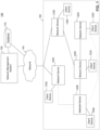
- FIG. 1 shows an example data communication network 100 in which various implementations as described herein may be practiced.
- Data communication network 100 includes, for example, a network 140, network management system 150, database 170, network devices 120A-120E, and client devices 130A-130E.
- the network devices 120A-120E and client devices 130A-130E form a service network 160, in which the network devices 120A-120E (collectively 120) provide data services to client devices 130A-130E (collectively 130).
- the network devices may be hardware-based or software-based switches, routers, splitters, or the like that facilitate delivery of data services to client devices 130.
- the components and arrangements shown in FIG. 1 are not intended to limit the disclosed embodiments, as the system components used to implement the disclosed processes and features can vary.
- each network device 120 may be associated with no, one, or many client devices 130.
- service network 160 may be based on one or more of on-premises network environments, virtualized (cloud) network environments, or combinations of on-premises and cloud networks. Consistent with embodiments described herein, various types of data may be communicated over service network 160, such as Internet (e.g., IP protocol) data, telephony or telecommunications data, satellite data, IoT-based data, cellular data, proprietary network data, and more.
- Internet e.g., IP protocol
- Network management system 150 is configured to manage service deliveries for the service network 160. For example, the network management system 150 may determine service routes and allocate resources for services to be delivered in the data communication network 100. The network management system 150 may also reallocate resources for the existing services when new service demands arrive at the data communication network 100. In some embodiments, the network management system 150 may manage sequences of service migrations when multiple services are to be reconfigured in the data communication network 100. In some embodiments, when a link failure occurs, the network management system 150 may identify restoration schemes for the disrupted service. For example, the network management system 150 may identify alternate service links that do not involve the failed communication link.
- the network management system 150 may identify a set of service links that is sufficient to satisfy the service demands in the data communication network 100 and in the meantime reduce the operation cost (e.g., in terms of equipment usage, bandwidth, processing activity, monetary cost, etc.) in the network.
- Network management system 150 can be a computer-based system including computer system components, desktop computers, workstations, tablets, handheld computing devices, memory devices, and/or internal network(s) connecting the components.
- Network 140 facilitates communication between the network management system 150 and the service network 160.
- Network management system 150 may send data to network devices 120 via network 140 to allocate resources for services in the data communication network 100.
- Network management system 150 may also receive data from network devices 120 via network 140 indicating the status of service links in the data communication network 100.
- Network 140 may be an electronic network.
- Network devices 120 may be configured to receive data over network 140 and process/analyze queries and data.
- Examples of network 140 include a local area network (LAN), a wireless LAN (e.g., a "WiFi” or mesh network), a Metropolitan Area Network (MAN) that connects multiple LANs, a wide area network (WAN) (e.g., the Internet), a dial-up connection (e.g., using a V.90 protocol or a V.92 protocol), a satellite-based network, a cellular-based network, etc.
- the Internet may include any publicly-accessible network or networks interconnected via one or more communication protocols, including, but not limited to, hypertext transfer protocol (HTTP/s) and transmission control protocol/internet protocol (TCP/IP).
- HTTP/s hypertext transfer protocol
- TCP/IP transmission control protocol/internet protocol
- the electronic network may also include one or more mobile device networks, such as a Long Term Evolution (LTE) network or a Personal Communication Service (PCS) network, that allow mobile devices (e.g., client devices 130) to send and receive data via applicable communication protocols, including those described above.
- LTE Long Term Evolution
- PCS Personal Communication Service
- network devices 120A and 120E are directly connected to network 140, and network devices 120B-120D connect to the network 140 via their connection to network device 120A and/or 120E.
- network devices 120B-120D may also directly connect to the network 140, or may indirectly connect to the network 140 through numerous other devices.
- Network devices 120 may be connected to one another via copper wire, coaxial cable, optical fiber, microwave links, or other satellite or radio communication components. Accordingly, network devices 120 may each have a corresponding communications interface (e.g., wireless transceiver, wired transceiver, adapter, etc.) to allow for such communications.
- network devices 120A-120E are connected to one another.
- network device 120A is connected to network device 120B
- network device 120B is connected to network devices 120A, 120C, and 120D
- network device 120C is connected to network devices 120B, 120D, and 120E
- network device 120D is connected to network device 120C
- network device 120E is connected to network device 120C.
- a network topology may be formed to present a graphical view of the service network 160, where each of the network device 120 corresponds to a network node or vertex in the network topology.
- the terms "node” and "vertex" are exchangeable.
- the network topology also shows the interconnection relationships among the network devices.
- the network management system 150 may obtain the connectivity status between the network devices and generate a network topology. In other embodiments, the network management system 150 may acquire the network topology from a server or a database associated with a service provider providing the service network.
- the service network 160 illustrated in FIG. 1 is merely an example, and the network topology of service network 160 can be different from the example without departing from the scope of the present disclosure.
- Network management system 150 may reside in a server or may be configured as a distributed system including network devices or as a distributed computer system including multiple servers, server farms, clouds, computers, or virtualized computing resources that interoperate to perform one or more of the processes and functionalities associated with the disclosed embodiments.
- Database 170 includes one or more physical or virtual storages coupled with the network management system 150.
- Database 170 may be configured to store information associated with the service network 160, such as the network topology, the capability of the network devices, the services and corresponding configurations provided by the service network, and so on.
- Database 170 may also be adapted to store processed information associated with the network topology and services in the service network 160, so as to facilitate efficient route configurations and resource allocations to satisfy the service demands in the service network 160.
- the data stored in the database 170 may be transmitted to the network management system 150 and/or the network devices 120.
- the database 170 is stored in a cloud-based server (not shown) that is accessible by the network management system 150 and/or the network devices 120 through the network 140. While the database 170 is illustrated as an external device connected to the network management system 150, the database 170 may also reside within the network management system 150 as an internal component of the network management system 150.
- network devices 120A-120E are connected with client devices 130A-130E respectively to deliver services.
- client devices 130A-130E include a display such as a television, tablet, computer monitor, video conferencing console, IoT device, or laptop computer screen.
- Client devices 130A-130E may also include video/audio input devices such as a video camera, web camera, or the like.
- client devices 130A-130E include mobile devices such as a tablet or a smartphone having display and video/audio capture capabilities. While FIG. 1 shows one client device 130 connected to each network device 120, one of ordinary skill in the art would appreciate that more than one client device may be connected to a network device and that in some instances a network device may not be connected to any client device.
- the data communication network 100 may include an optical network, where the network devices 120 are interconnected by optical fiber links.
- the optical fiber links may be capable of conveying a plurality of optical channels using a plurality of specified different optical wavelengths.
- the optical network may be based on a wavelength division multiplexing (WDM) physical layer.
- WDM optical signal comprises a plurality of transmission channels, each channel carrying an information signal modulated over a carrier wavelength.
- the network devices 120 may be provided with the ability to switch a channel from an input fiber to an output fiber, and to add/drop traffic.
- the network devices 120 may include a wavelength switch or an optical add/drop multiplexer that performs optical add, drop, and pass through.
- the network devices 120 may include optical or optical/electrical elements being adapted to perform to various functions such as compensating, amplifying, switching, restoring, performing wavelength conversion of incoming optical signals, etc.
- the optical fiber links may include dispersion compensation fibers (DCF), optical filters, amplifiers and other relevant optical components that are used for operation of optical networks.
- the network management system 150 or databased 170 may store topologic data includes information about optical channels and their associated wavelengths.
- the data communication network 100 may include a network controller (not shown) configured to improve network utilization by providing an optimal routing and wavelength assignment plan for a given set of service demands.
- a service demand is a request for a wavelength between two nodes in the network.
- a circuit is provisioned to satisfy a service demand and is characterized by a route and assigned wavelength number.
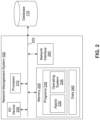
- FIG. 2 shows a diagram of an example network management system 150, consistent with the disclosed embodiments.
- the network management system 150 may be implemented as a specially made machine that is specially programed to perform functions relating to managing a data communication network.
- the special programming at the network management system 150 enables network management system to determine service routes and allocate resources for services to be delivered in the data communication network 100.
- the network management system 150 includes a bus 202 (or other communication mechanism) which interconnects subsystems and components for transferring information within the network management system 150.
- the network management system 150 includes one or more processors 210, input/output ("I/O") devices 250, network interface 260 (e.g., a modem, Ethernet card, or any other interface configured to exchange data with a network), and one or more memories 220 storing programs 230 including, for example, server app(s) 232, operating system 234, and data 240, and can communicate with an external database 170 (which, for some embodiments, may be included within the network management system 150).
- I/O input/output
- network interface 260 e.g., a modem, Ethernet card, or any other interface configured to exchange data with a network
- memories 220 storing programs 230 including, for example, server app(s) 232, operating system 234, and data 240, and can communicate with an external database 170 (which, for some embodiments, may be included within the network management
- the processor 210 may be one or more processing devices configured to perform functions of the disclosed methods, such as a microprocessor manufactured by Intel TM or manufactured by AMD TM .
- the processor 210 may comprise a single core or multiple core processors executing parallel processes simultaneously.
- the processor 210 may be a single core processor configured with virtual processing technologies.
- the processor 210 may use logical processors to simultaneously execute and control multiple processes.
- the processor 210 may implement virtual machine technologies, or other technologies to provide the ability to execute, control, run, manipulate, store, etc. multiple software processes, applications, programs, etc.
- the processor 210 may include a multiple-core processor arrangement (e.g., dual, quad core, etc.) configured to provide parallel processing functionalities to allow the network management system 150 to execute multiple processes simultaneously. It is appreciated that other types of processor arrangements could be implemented that provide for the capabilities disclosed herein.
- a multiple-core processor arrangement e.g., dual, quad core, etc.
- the memory 220 may be a volatile or non-volatile, magnetic, semiconductor, tape, optical, removable, non-removable, or other type of storage device or tangible or non-transitory computer-readable medium that stores one or more program(s) 230 such as server apps 232 and operating system 234, and data 240.
- program(s) 230 such as server apps 232 and operating system 234, and data 240.
- non-transitory media include, for example, a flash drive a flexible disk, hard disk, solid state drive, magnetic tape, or any other magnetic data storage medium, a CD-ROM, any other optical data storage medium, any physical medium with patterns of holes, a RAM, a PROM, and EPROM, a FLASH-EPROM or any other flash memory, NVRAM, a cache, a register, any other memory chip or cartridge, and networked versions of the same.
- the network management system 150 may include one or more storage devices configured to store information used by processor 210 (or other components) to perform certain functions related to the disclosed embodiments.
- the network management system 150 may include memory 220 that includes instructions to enable the processor 210 to execute one or more applications, such as server apps 232, operating system 234, and any other type of application or software known to be available on computer systems.
- the instructions, application programs, etc. may be stored in an external database 170 (which can also be internal to the network management system 150) or external storage communicatively coupled with the network management system 150 (not shown), such as one or more database or memory accessible over the network 140.
- the database 170 or other external storage may be a volatile or non-volatile, magnetic, semiconductor, tape, optical, removable, non-removable, or other type of storage device or tangible or non-transitory computer-readable medium.
- the memory 220 and database 170 may include one or more memory devices that store data and instructions used to perform one or more features of the disclosed embodiments.
- the memory 220 and database 170 may also include any combination of one or more databases controlled by memory controller devices (e.g., server(s), etc.) or software, such as document management systems, Microsoft TM SQL databases, SharePoint databases, Oracle TM databases, Sybase TM databases, or other relational databases.
- the network management system 150 may be communicatively connected to one or more remote memory devices (e.g., remote databases (not shown)) through network 140 or a different network.
- the remote memory devices can be configured to store information that the network management system 150 can access and/or manage.
- the remote memory devices could be document management systems, Microsoft TM SQL database, SharePoint databases, Oracle TM databases, Sybase TM databases, or other relational databases. Systems and methods consistent with disclosed embodiments, however, are not limited to separate databases or even to the use of a database.
- the programs 230 include one or more software modules configured to cause processor 210 to perform one or more functions of the disclosed embodiments.
- the processor 210 may execute one or more programs located remotely from one or more components of the data communication network 100.
- the network management system 150 may access one or more remote programs that, when executed, perform functions related to disclosed embodiments.
- server app(s) 232 causes the processor 210 to perform one or more functions of the disclosed methods.
- the server app(s) 232 cause the processor 210 to determine service routes and allocate resources for services to be delivered in the data communication network 100.
- the program(s) 230 may include the operating system 234 performing operating system functions when executed by one or more processors such as the processor 210.
- the operating system 234 may include Microsoft Windows TM , Unix TM , Linux TM , Apple TM operating systems, Personal Digital Assistant (PDA) type operating systems, such as Apple iOS TM , Google Android TM , Blackberry OS TM , or other types of operating systems. Accordingly, disclosed embodiments may operate and function with computer systems running any type of operating system 234.
- the network management system 150 may also include software that, when executed by a processor, provides communications with network 140 through the network interface 260 and/or a direct connection to one or more network devices 120A-120E.
- the data 240 may include, for example, network configurations, requirements of service demands, routes for existing service, capacity of the network devices and each service path, and so on.
- the data 240 may include network topology of the service network 160, capacity of the network devices 120, and capacity of the communication link between the network devices 120.
- the data 240 may also include requirements of service demands and resource allocation for each service in the service network 160.
- the network management system 150 may also include one or more I/O devices 250 having one or more interfaces for receiving signals or input from devices and providing signals or output to one or more devices that allow data to be received and/or transmitted by the network management system 150.
- the network management system 150 may include interface components for interfacing with one or more input devices, such as one or more keyboards, mouse devices, and the like, that enable the network management system 150 to receive input from an operator or administrator (not shown).
- path refers to a source-destination physical or logical route (such as an A-Z path).
- a path can have one or more configurations, as a result of allocations of different resources, such as different wavelength assignments.
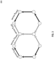
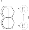
- FIG. 3 is a diagram of an example service migration map 300, consistent with the present disclosure.
- FIG. 3 illustrates configurations for services A and B in the data communication network.
- each service demand can be identified by a tuple ⁇ s, t>, with s and t being the source and destination node of the service demand.
- service A that is to be delivered from source node "d" to destination node “a” can be identified by ⁇ d, a>
- service B that is to be delivered from source node "j" to destination node “g” can be identified by ⁇ j, g>.
- a network node refers to a network component, such as network devices 120, that communicates with one another according to predetermined protocols by means of wired or wireless communication links.
- service A is routed along path d -> c -> b -> a
- service B is routed along path j -> f -> e -> g.
- service A is rerouted to link d -> f -> e -> a
- service B is rerouted to path j -> i -> h -> g.
- the path f ->e is part of the service route for service B before service migration, and is also part of the service route for service A after service migration.
- a migration sequence is required to minimize the service disruption.
- FIG. 3 serves as an example of service migration map.
- a data communication network may provide more than two services, and there may be more than one overlapping path between migrations of the services.
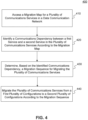
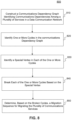
- FIG. 4 is a flowchart of an example process 400 for migrating communications services in a data communication network, in accordance with embodiments of the present disclosure.
- the steps associated with this example process may be performed by, for example, a processor of the network management system 150 of FIG. 1 .
- the example process 400 allows a service provider to migrate services in a data communication network according to a certain order so as to reduce the disruption of services during the service migration.
- the network management system accesses a migration map for a plurality of communications services in a data communication network.
- the migration map may show routes of services before and after the migration.
- the migration map may also identify resources allocated on paths for services, such as a wavelength configured for the service on the associated service paths.
- the migration map may be stored in a database connected to the network management system, such as the database 170, or stored locally in the network management system.
- the migration map may be generated separately by a network controller based on the QoS requirements of services in the network so as to satisfy the service demands and achieve efficient use of the network.
- the migration map may be continuously or periodically updated based on the current network status or the service demands.
- the network management system accesses the migration map in response to a user request to retrieve a sequence of migrations for the services.
- the user request may be received via the I/O device 250.
- the network management system may be configured to access the migration map periodically to identify whether a migration sequence is to be determined.
- the network management system may access the migration map in response to receiving a notification that the migration map is updated and/or service migrations are about to occur. The notification may be received from a network controller that allocates routes and resources for services in the network.
- the network management system identifies a communications dependency between a first service and a second service in the plurality of communications services according to the migration map.
- the migration map may identify that the first service is configured to migrate from a first route to a second route, the second service is configured to migrate from a third route to a fourth route, and the third route overlaps with the second route.
- Communications dependency means that a service cannot be moved to its final state (e.g., route and wavelength) until some other service occupying overlapping spans is moved out.
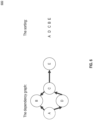
- FIG. 5 is a diagram illustrating a process 500 for constructing a dependency graph according to a migration map, in accordance with embodiments of the present disclosure.
- service A is routed along route R'1: d -> c -> b -> a
- service B is routed along route R1: j -> f -> e -> g.
- service A is rerouted to route R'2: d -> f -> e -> a
- service B is rerouted to route R2: j -> i -> h -> g.
- the data communication network is an optical network, where the wavelength assigned for service A before and after migration is ⁇ 1 and ⁇ 2 respectively, and the wavelength assigned for service B before and after migration is ⁇ 2 and ⁇ 3 respectively.
- route R'2 for service A overlaps with R1 for service B over the path f - > e
- the wavelength assigned for service A after migration is the same as the wavelength assigned for service B before migration.
- a directed edge from B to A is added, as shown in FIG. 5 .
- a directed edge from ⁇ to ⁇ is added if an old route of ⁇ before migration overlaps a new route of ⁇ after migration.
- the wavelength assigned to an old route of ⁇ before migration equals the wavelength assigned to a new route of ⁇ after migration.
- a dependency graph is constructed.
- the diagrams depicted in FIG. 5 are examples only and are not intended to be limiting.
- the network management system determines, based on the identified communications dependency, a migration sequence for migrating the plurality of communications services in the data communication network. For example, based on the identified communications dependency between services A and B shown in FIG. 5 , the network management system determines that migration of service B should occur before migration of service A.
- a migration sequence (B, A) can be formed, in which service B is the first to migrate in the migration sequence, and service A is the second to migrate in the migration sequence.
- a dependency graph may be constructed based on the identified communications dependency of service demands in the migration map.
- the network management system creates a node n i in the dependency graph.
- the network management system then creates a directed edge from node n i to node n j if an old route of node n i before migration overlaps a new route of n j after migration.
- a directed edge is created from node n i to node n j if the wavelength assigned to an old route of n i , before migration equals the wavelength assigned to a new route of n j after migration.
- a dependency graph 600 is an example dependency graph 600, in accordance with embodiments of the present disclosure.
- the diagrams depicted in FIG. 6 are examples only and are not intended to be limiting.
- a dependency graph is constructed including service demands A-E.
- the dependency graph shows directed edges between services A-E, such as edges A->B, A->D, D->C, C->B, and C->E.
- the directed edges between the services are identified using the method described above in step 420.
- an edge exists between services A and D and is directed from service A to service D, meaning that an old route of A before migration overlaps a new route of D after migration.
- the directed edge from service A to service D also means that the wavelength assigned to an old route of A before migration equals the wavelength assigned to a new route of D after migration.
- a migration sequence for services can be acquired according to a topological sort of nodes in the dependency graph. For example, according to the dependency graph shown in FIG. 6 , a migration sequence (A, D, C, B, E) can be formed, with service A being the first to migrate in the migration sequence and service E being the last to migrate in the migration sequence.
- the migration sequence allows the service demands in the network to be migrated smoothly with minimal service disruption.
- the network management system migrates the plurality of communications services from a first plurality of configurations to a second plurality of configurations according to the migration sequence.
- the configurations for services may include a selected route and/or a wavelength assignment for each service demand.
- each of the services A-E shown in FIG. 6 may be migrated to a different route according to the order identified in the migration sequence (A, D, C, B, E).
- Different resources such as bandwidth, wavelength, time slots, may also be allocated for each of the services after the migration.
- each of the services A-E shown in FIG. 6 may also be migrated to a different wavelength.
- parallel processing can be performed to reduce the time to migrate the services.
- the network management system may identify the vertices of the dependency graph that have no in-going edges and group them together.
- the group of vertices may be added to the end of the migration sequence, where migrations of communications services corresponding to the group of vertices can be performed in parallel.
- the network management system may then delete the group of vertices from the dependency graph and repeat the above steps until no more vertices remain in the dependency graph.
- the dependency graph may include one or more cycles, where a dependency cycle starts and ends on the same service, making it difficult to determine the migration sequence based on the dependency graph.
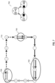
- FIG. 7 is a diagram illustrating a dependency cycle in a data communication network, in accordance with embodiments of the present disclosure. The example diagram depicted in FIG. 7 is an example only and is not intended to be limiting.
- the left diagram illustrates a network graph 710 including nodes a-n and connectivity between the nodes a-n.
- Services A, B, C are provided by the network, where service A ⁇ j, b> is from source node “j" to destination node “b", service B ⁇ a, g> is from source node “a” to destination node “g”, and service C ⁇ f, 1> is from source node "f" to destination node "1".
- path 720, a->b is an overlapping path between service A and service B
- path 730, f->g is an overlapping path between service B and service C
- path 740, j->1 is an overlapping path between service A and service C.
- service A is to be migrated to another wavelength that is the same as an wavelength configuration for service B before migration of service B
- service B is to be migrated to another wavelength that is the same as an wavelength configuration for service C before migration of service C
- service C is to be migrated to another wavelength that is the same as an wavelength configuration for service A before migration of service A.
- a cycle is formed in the corresponding dependency graph 750, with directed edges from service B to service A, service C to service B, and service A to service C.
- the dependency cycle presents a deadlock condition such that it is difficult to determine the migration sequence of services A, B, C based on the dependency graph 750. For example, if a migration sequence (A, C, B) is used, service A cannot migrate to the new wavelength without first migrating service C out of its old wavelength, causing a disruption of service A.
- FIG. 8 is a flowchart of an example process 800 for migrating communications services in a data communication network, consistent with the disclosed embodiments.
- the steps associated with this example process may be performed by, for example, a processor of the network management system 150 of FIG. 1 .
- the example process 800 provides a method to migrate services in a data communication network when there are one or more cycles in the dependency graph of the services.
- the network management system constructs a communications dependency graph identifying communications dependencies among a plurality of services in a data communication network.
- the communications dependency graph includes a plurality of vertices, each of the plurality of vertices corresponding to a pre-migration configuration and a post-migration configuration of a service in the data communication network.
- node and “vertex” may be used interchangeably.
- a corresponding node n i is created in the communications dependency graph.
- a directed edge from node n i to node n j is created in the communications dependency graph if the current pre-migration route of service d i , overlaps with the final post-migration route of service d j in the migration map.
- the network management system identifies one or more cycles in the communications dependency graph.
- each of the cycles may include at least three vertices corresponding to at least three services in the plurality of communications services.
- the network management system may look for a cycle that starts and ends on the same vertex to detect the cycle. If no cycle is detected in the dependency graph, the network management system may determine a migration sequence according to the method described in connection with FIG. 4 .
- the network management system identifies a special vertex in each of the one or more cycles. For example, the network management system may identify node A in the dependency cycle 750 of FIG. 7 as a special vertex. As another example, the network management system may identify node B in the dependency cycle 750 of FIG. 7 as a special vertex. In some embodiments, a node corresponding to a service that can be delivered using a temporary wavelength different from the pre-migration wavelength and post-migration wavelength may be selected as the special vertex.
- the process 800 does not limit how a special vertex is chosen in a dependency cycle.
- FIG. 9 is a diagram illustrating a process 900 for breaking a dependency cycle, in accordance with embodiments of the present disclosure.
- node A in the dependency cycle 910 is identified as the special vertex, where node A corresponds to service A with a pre-migration configuration of route R 1 with wavelength ⁇ 1 and a post-migration configuration of route R 2 with wavelength ⁇ 2 .
- a temporary wavelength may be used to break the dependency cycle 910.
- FIG. 9 is a diagram illustrating a process 900 for breaking a dependency cycle, in accordance with embodiment
- node A is first migrated to a temporary wavelength ⁇ temp , and an additional node A' may be added to the dependency graph.
- the additional node A' corresponds to a pre-migration configuration of route R 1 with wavelength ⁇ temp and a post-migration configuration of route R 2 with wavelength ⁇ 2 .
- a directed edge from A to A' may also be added in the acyclic dependency graph 920. In doing so, the dependency cycle is broken into an acyclic dependency graph 920, and a migration sequence may be determined based on the acyclic dependency graph 920.
- the dependency graph includes multiple cycles, each of the cycles can be broken into an acyclic dependency graph using the above-described process.
- the network management system determines, based on the broken cycles, a migration sequence for migrating the plurality of communications services. For example, after the dependency cycle 910 in the left diagram of FIG. 9 is broken into the acyclic dependency graph 920, a migration sequence (A, C, B, A') may be determined according to the topological sort of the acyclic dependency graph 920. In the migration sequence (A C B A'), service A is moved twice, the first time being migrated to a temporary wavelength and the second time being migrated to the final post-migration route and wavelength of service A. By using the temporary wavelength to break the dependency cycle and determine a migration sequence, the deadlock condition of the dependency cycle is resolved, and the services can transit to the post-migration configurations smoothly with minimal service disruption.
- restoration paths will need to be provided for services affected by the network link failure.
- Computing the restoration paths may be complex in a large network, and the computation may be performed at a central server which distributes the restoration paths to the network devices via configuration instructions.
- the configuration instructions may have a large size to include restoration paths for all possible link failures and link failure combinations.
- the disclosed embodiments provide a data structure that can be computed at a central service and sent to the network devices. The network devices may then compute the restoration paths using the data structure to satisfy the service demands when a network link failure occurs.
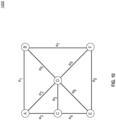
- FIG. 10 is a diagram illustrating a network graph 1000 in a data communication network, in accordance with embodiments of the present disclosure.
- the network graph 1000 contains network nodes ⁇ A, B, C, D, E, F ⁇ .
- the direct connection between two nodes is referred to as an edge, such as the connection between (A, B).
- the network graph 1000 includes 10 edges ⁇ e 0 , ... , e 9 ⁇ , i.e., the connections between nodes (E, F), (A, B), (A, D), (A, C), (C, E), (C, D), (B, D), (B, F), (D, E), (D, F), respectively.
- a path of a service link refers to a series of service paths in which an end vertex of a service path is the beginning vertex of a next service path.
- Table 1 shows paths of service links ⁇ r 1 , ..., r 6 ⁇ . Table 1.
- a path of a service link satisfies a service demand ⁇ x, y> if the beginning vertex of the first service path is x and the end vertex of the last service path is y.
- service link r 4 consists of a path through nodes (A, C, D)
- service link r 5 consists of a path through nodes (A, B, D, E).
- a service demand ⁇ A, F> in the network which may be satisfied by service path (r 1 , r 2 ). If any of the edges among ⁇ e 0 , ... , e 9 ⁇ fail, a restoration path may need to be found for service demand ⁇ A, F>. For example, if edge e 1 fails, no restoration path is needed. In the event of a link failure in edge e 2 , as the current service path (r 1 , r 2 ) routes though e 2 , a restoration path not routing through e 2 , such as service path (r 4 , r 2 ), will need to be found to satisfy the service demand.
- a restoration path not routing through e 9 such as service path (r 1 , r 3 ) will need to be found to satisfy the service demand.
- a restoration path not routing through e 2 or e 9 such as service path (r 5 , r 6 ) will need to be found to satisfy the service demand.
- the number of restoration paths that need to be pre-computed can be large.
- the disclosed embodiments provide a method to identify the restoration paths without having to store all the paths for each service demand and each series of link failures.
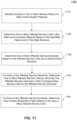
- FIG. 11 is a flowchart of an example process 1100 for providing restoration paths in a data communication network, consistent with the disclosed embodiments.
- the steps associated with this example process is described in relation to a network management system, such as network management system 150 of FIG. 1 .
- a network management system such as network management system 150 of FIG. 1 .
- One of ordinary skill in the art would appreciate that the steps associated with this example process may also be performed by, for example, a processor of the network devices 120 or a server of the data communication network.
- the example process 1100 allows a network device or a network management system to provide restoration paths in a data communication network without having to store all the paths for each service demand and each series of link failures.
- the network management system identifies a failure in one or more service paths of the data communication network. For example, the network management system may identify a link failure by detecting service degradation in one or more services currently provided by the data communication network. As another example, the network management system may identify a link failure by receiving feedback from network devices indicating a failure to send or receive data by the network devices. Other methods known by one of ordinary skill in the art may be used to identify a failure in one or more service paths of the data communication network, which are not describe herein for the sake of brevity.
- the network management system determines one or more affected service links in the data communication network based on the identified failure and a first data structure.
- the first data structure includes a plurality of service paths and one or more corresponding service links that use the service path.
- FIG. 12 is a diagram illustrating another network graph 1200 in a data communication network, in accordance with embodiments of the present disclosure. As shown in FIG. 12 , there are seven service links ⁇ r 1 , ..., r 7 ⁇ provided by the data communication network, where each service link consists of one or more service paths. The service links ⁇ r 1 , ..., r 7 ⁇ that can be used to satisfy service demands and their corresponding metrics are provided in Table 2.
- the metric indicates a cost associated with the service links and may be additive in service links that includes two or more edges.
- Table 2 Example Service Links in a Network Service Links Service Path Metric r 1 (A, B) 1 r 2 (A, C, E) 9 r 3 (E, F) 10 r 4 (B, F) 5 r 5 (B, D) 4 r 6 (B, D, E) 12 r 7 (A, D) 3
- the first data structure may include each of the service paths, such as each edge in the network graph, and the corresponding service link that use the path, as shown in Table 3.
- a path (x, y) represents the path between node x and node y.
- Table 3 Example First Data Structure Service Path Corresponding Service Links (A, B) ⁇ r 1 ⁇ (A, C) ⁇ r 2 ⁇ (A, D) ⁇ r 7 ⁇ (B, D) ⁇ r 5 , r 6 ⁇ (B, F) ⁇ r 4 ⁇ (C, D) N/A (C, E) ⁇ r 2 ⁇ (D, E) ⁇ r 6 ⁇ (D, F) N/A (E, F) ⁇ r 3 ⁇
- the first data structure includes each edge of the network graph and the corresponding service links that uses the edge. For example, for the edge (A, B), the only service link that uses edge (A, B) is r 1 , and for the edge (B, D), both service links r 5 and r 6 use edge (B, D).
- the network management system can determine the affected service links in the data communication network when one or more service paths of the network, i.e., edges of the network graph, fail to operate properly. For example, in the event edge (B, D) fails, it can be determined that the affected service links include r 5 and r 6 using the first data structure in Table 3.
- the network management system determines one or more affected service demands based on the affected service links and a second data structure.
- the second data structure includes a plurality of service links provided by the data communication network and one or more service demands corresponding to one or more of the service links.
- the one or more service demands in the second data structure require service delivered from a first service node to a second service node, and corresponding service links can be used to satisfy the corresponding service demands.
- Table 4 provides an example of the second data structure for the network graph 1200 shown in FIG. 12 . Table 4.
- service links r 1 , r 2 , r 4 , and r 5 each are used by one corresponding service demand
- service links r 3 and r 6 are not used by any service demand
- service link r 7 is used by two service demands.
- the network management system can determine the affected service demands in the data communication network when one or more service links of the network are affected because of a failure in one or more network paths.
- the network management system determines one or more allowed service links by removing the affected service links from a set of corresponding service links for the affected service demands.
- the network management system constructs a network graph including a plurality of service nodes and one or more service links for each of the affected service demands, where the affected service links are excluded from the network graph.
- the allowed service links for the affected service demands may be determined. For example, referring to FIG. 12 , in the event service link r 2 and service demand ⁇ E, D> are affected, the network management system may create a new network graph by removing service link r 2 from the network graph 1200, so as to determine the allowed service links for service demand ⁇ E, D>.
- the network management system may determine the allowed service links for the affected service demands based on a third data structure.
- the third data structure includes a plurality of service demands and a corresponding set of service links that can be used by the service demand.
- the third data structure may be predefined by a network server. Table 5 provides an example of the third data structure for the network graph 1200 shown in FIG. 12 . Table 5.
- a number of service links are allowed for each of the service demands.
- the network management system may remove r 2 from the corresponding set of service links in the third data structure and determine that the allowed service links for service demand ⁇ E, D> are ⁇ r 3 , r 4 , r 5 , r 6 , r 7 ⁇ .
- the network management system for each of the affected service demands, determines one or more restoration paths based on the one or more allowed service links.
- the restoration paths are determined based on a fourth data structure.
- the fourth data structure includes the service links provided by the data communication network, one or more corresponding service paths, and a corresponding cost metric.
- Table 2 described above may be a fourth data structure for the network illustrated in FIG. 12 .
- the restoration paths are determined by using a Dijkstra's algorithm.
- the network management system may construct another network graph based on the allowed service links identified in step 1140 and using information in the fourth data structure.
- the network management system may then run the Dijkstra's algorithm on the constructed network graph to determine the restoration paths for the affected service demands.
- Dijkstra's algorithm is an algorithm for finding the shortest paths between nodes in a graph, and the details of the Dijkstra's algorithm are not provided in this disclosure. Methods known to one of ordinary skill in the art to implement the Dijkstra's algorithm can be used to identify restoration paths for the affected service demands.
- the example process 1100 allows the restoration paths to be determined in real time when a network link failure occurs. Moreover, the size of the first and second data structures are relatively small, and so it does not take much storage space to store the first and second data structures. This also allows the data structures to be stored in the network devices. In some embodiments, the first, second, third, and fourth data structures are stored in the network devices. Further, because constructing a new network graph and running the Dijkstra's algorithm are computationally efficient, the network devices may be able to determine the restoration paths in a distributed manner rather than relying on a network management system or a server to determine the restoration paths.
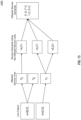
- FIG. 13 is a diagram illustrating an example process 1300 for identifying affected service demands when one or more service paths in a data communication network fail, in accordance with embodiments of the present disclosure.
- the steps associated with this example process is described in relation to a network management system, such as network management system 150 of FIG. 1 .
- a network management system such as network management system 150 of FIG. 1 .
- One of ordinary skill in the art would appreciate that the steps associated with this example process may also be performed by, for example, a processor of the network devices 120 or a server of the data communication network.
- the network graph 1200 in FIG. 12 is used as the graph in the data communication network, and a link failure in edges (B, D) and (A, D) is identified.
- restoration paths need to be provided for service demands affected by the link failure.
- the network management system determines service links that are affected by the identified failure.
- the network management system may use the first data structure shown in Table 3 above to identify the affected service links.
- service links r 5 and r 6 are affected by the failure of edge (B, D)
- service link r 7 is affected by the failure of edge (A, D).
- service demands that use the affected service links may be determined using the second data structure shown in Table 4 above.
- service demand ⁇ A, F> is affected by the affected service link r 5
- service demands ⁇ A, F> and ⁇ E, D> are affected by the affected service link r 7
- no service demand is affected by the affected service link r 6 .
- the set of service demands that are affected by the link failure includes service demands ⁇ A, F> and ⁇ E, D>.
- the network management system then needs to determine restoration paths for rerouting the affected service demands.
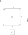
- FIG. 14 is a diagram illustrating another network graph 1400 for identifying restoration paths for affected service demands in a data communication network, in accordance with embodiments of the present disclosure.
- the network management system constructs another network graph 1400 for the affected service demand ⁇ A, F> by removing the affected service links r 5 , r 6 , and r 7 from the original network graph 1200 before the link failure occurs.
- service link r 1 is not included in the allowed service links for service demand ⁇ A, F> identified in the third data structure of Table 5, r 1 is also removed from the network graph 1200.
- the network graph 1400 contains service links r 2 , r 3 , and r 4 .
- node C is not an end point for any of the allowed service links for service demand ⁇ A, F>, node C is also removed from the network graph 1200, and the network graph 1400 contains nodes A, B, D, E, F.
- the network management system may run the Dijkstra's algorithm and determine that the path (r 2 , r 3 ) may be used as the restoration path for service demand ⁇ A, F>.
- similar processing can be performed to identify the restoration path for the other affected service demand ⁇ E, D >.
- the network graphs 1200 and 1400 are described herein for illustrative purposes, and the disclosed embodiments can be used to identify restoration paths for different network graphs and service demands provided in the network.
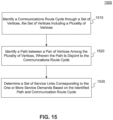
- FIG. 15 is a flowchart of an example process 1500 for restoring service demands in a data communication network, consistent with the disclosed embodiments.
- the steps associated with this example process is described in relation to a network management system, such as network management system 150 of FIG. 1 .
- a network management system such as network management system 150 of FIG. 1 .
- One of ordinary skill in the art would appreciate that the steps associated with this example process may also be performed by, for example, a processor of the network devices 120 or a server of the data communication network.
- the example process 1500 allows service demands to be restored by using remaining available service links when one or two service links assigned to the service demands fail.
- the network management system identifies a communications route cycle through a set of vertices.
- the set of vertices includes a plurality of vertices, each of the plurality of vertices corresponding to an end point of at least one service demand.
- the plurality of vertices includes two vertices corresponding to end points of each of the service demands.
- a vertex corresponds to a network node, such as a network device 120, and the terms "vertex" and "node” may be used interchangeably.
- FIG. 16 is a diagram illustrating a communications route cycle 1600 in a data communication network, in accordance with embodiments of the present disclosure.
- the communications route cycle 1600 is a part of a path cycle.
- a path cycle refers to a cycle combined with the additional paths that are disjoint to the edges of the cycle.
- the service demands in the data communication network include ⁇ A, C>, ⁇ B, E> ⁇ E, G>, and one or more service links are to be assigned to each of the service demands. As shown in FIG.
- the communications route cycle 1600 includes vertices A, B, C, E, G, which are end points, i.e., source nodes or destination nodes, of the service demands ⁇ A, C>, ⁇ B, E>, ⁇ E, G>.
- the communications route cycle 1600 also includes vertices D, F, H that are not end points of a demand. As shown in FIG.
- the communications route cycle 1600 consists of a cycle ⁇ A, B, C, D, G, F, E, A ⁇ that goes through the vertices that are end points A, B, C, E, G of the service demands ⁇ A, C>, ⁇ B, E>, ⁇ E, G> and vertices D, F that are not end points of a demand.
- the communications route cycle 1600 illustrated in FIG. 16 is an example of a communications route cycle, and a communications route cycle may be different from this example without departing from the scope of the present disclosure.
- the network management system identifies a path between a pair of vertices among the plurality of vertices, the pair of vertices corresponding to end points of a service demand, where the path is disjoint to the communications route cycle.
- the identified path is identified based on it being the shortest among paths between the pair of vertices that are -disjoint to edges of the communications route cycle. In other embodiments, the identified path is identified based on it having the least cost among paths between the pair of vertices that are disjoint to the edges of the communications route cycle.
- the network management system may identify a path between any pair of end points of service demands ⁇ A, C>, ⁇ B, E>, ⁇ E, G>.
- the network management system may identify the path A->H->C that is disjoint to the edges of the communications route cycle 1600 for service demand ⁇ A, C>.
- the network management system may further identify the path B->E for service demand ⁇ B, E> that is disjoint to the communications route cycle 1600 and the path E->H->G for service demand ⁇ E, G> that is disjoint to the edges of the communications route cycle 1600.
- a path that is disjoint to the communications route cycle 1600 is identified for each of the service demands ⁇ A, C>, ⁇ B, E>, ⁇ E, G>.
- the network management system determines a set of service links corresponding to the one or more service demands based on the identified path and communication route cycle.
- the set of service links includes the identified path for the corresponding service demand.
- the network management system may assign service links ⁇ A->B->C, A->E->F->G->D->C, A->H->C ⁇ to service demand ⁇ A, C>.
- the network management system may assign service links ⁇ B->A->E, B->C->D->G->F->E, B->E ⁇ to service demand ⁇ B, E>, such that when any two edges fail in the communications route cycle 1600, the service demand ⁇ B, E > can still be satisfied with other available service links assigned to the service demand ⁇ B, E >.
- the network management system may assign service links ⁇ E->F->G, E->A->B->C->D->G, E->H->G ⁇ to service demand ⁇ E, G>, such that when any two edges fail in the communications route cycle 1600, the service demand ⁇ E, G > can still be satisfied with other available service links assigned to the service demand ⁇ E, G >.
- the network management system may assign sets of service links for the service demands by solving the service demands together as a set. For example, the network management system may determine a first set of service links on the communications route cycle that terminate at end points of the set of demands in the data communication network. The network management system may assign the first set of service links to every demand. For example, referring to FIG. 16 , the network management system may identify a first set of service links ⁇ A->B, B->C, C->D->G, G->F->E, E->A ⁇ for service demands ⁇ A, C>, ⁇ B, E>, ⁇ E, G>.
- Each of the service links A->B, B->C, C->D->G, G->F->E, and E->A is on the communications route cycle 1600 and terminates at end points of service demands ⁇ A, C>, ⁇ B, E>, or ⁇ E, G>.
- the service links ⁇ A->B, B->C, C->D->G, G->F->E, E->A ⁇ are assigned to each of the service demands ⁇ A, C>, ⁇ B, E>, ⁇ E, G>.
- the network management system may additionally assign the disjoint path with the same end points as the service demand to the corresponding service demand.
- the network management system may assign an additional service link A->H->C for service demand ⁇ A, C>, an additional service link B->E for service demand ⁇ B, E>, and an additional service link E->H->G for service demand ⁇ E, G>.
- the service links assigned for service demand ⁇ A, C> are ⁇ A->B, B->C, C->D->G, G->F->E, E->A, A->H->C ⁇
- the service links assigned for service demand ⁇ B, E> are ⁇ A->B, B->C, C->D->G, G->F->E, E->A, B->E ⁇
- the service links assigned for service demand ⁇ E, G> are ⁇ A->B, B->C, C->D->G, G->F->E, E->A, E->H->G ⁇ .
- the network management system may first identify a communications route cycle that is the shortest among all cycles going through all end points of the given service demands. For each service demand, the network management system may then identify a path that is shortest among all paths between the end points of the service demand that are disjoint to the edges of the communications route cycle. In other embodiments, the network management system may first identify a communications route cycle that is of the least cost among all cycles going through all end points of the given service demands. For each service demand, the network management system may then identify a path that is of the least cost among all paths between the end points of the service demand that are disjoint to the edges of the communications route cycle.
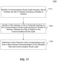
- FIG. 17 is a flowchart of another example process 1700 for restoring service demands in a data communication network, consistent with the disclosed embodiments.
- the steps associated with this example process is described in relation to a network management system, such as network management system 150 of FIG. 1 .
- a network management system such as network management system 150 of FIG. 1 .
- One of ordinary skill in the art would appreciate that the steps associated with this example process may also be performed by, for example, a processor of the network devices 120 or a server of the data communication network.
- the example process 1500 allows service demands to be restored by using remaining available service links when one or two edges fail and cause the resulting service links assigned to the service demands fail.
- the network management system identifies a communications route cycle through a set of vertices.
- the set of vertices includes a plurality of vertices, each of the plurality of vertices corresponding to an end point ( i.e., a source or destination node) of at least one service demand.
- the plurality of vertices includes two vertices corresponding to end points of each of the service demands.
- FIG. 18 is a diagram illustrating another communications route cycle 1800 in a data communication network, in accordance with embodiments of the present disclosure.
- the communications route cycle 1800 may also be referred to as a star cycle.
- the set of service demands in the data communication network includes ⁇ A, B>, ⁇ B, E>, ⁇ A, F>, ⁇ E, G>, ⁇ A, C, ⁇ C, E>, ⁇ F, G>, ⁇ B, G>.
- One or more service links are to be assigned to each of the service demands.
- the communications route cycle 1800 includes vertices A, B, C, E, F, G, which are end points, i.e., source nodes or destination nodes, of the set of service demands.
- the communications route cycle 1800 also includes vertex D that is not an end point of a demand. As shown in FIG. 18 , the communications route cycle 1800 consists of a cycle ⁇ A, B, C, D, G, F, E, A ⁇ that goes through the end points of the set of service demands A, B, C, E, F, G.
- the communications route cycle 1800 illustrated in FIG. 18 is an example of a communications route cycle, and a communications route cycle may be different from this example without departing from the scope of the present disclosure.
- the network management system identifies a path between a pair of antipodal vertices on the communications route cycle among the plurality of vertices, where the path is disjoint to the edges of the communications route cycle.
- the identified path is identified based on it being the shortest among paths between the pair of antipodal vertices that are disjoint to the communications route cycle. In other embodiments, the identified path is identified based on it having the least cost among paths between the pair of antipodal vertices that are disjoint to the edges of the communications route cycle.
- the network management system may identify pairs of antipodal vertices including (A, G), (B, F), and (C, E). The network management system may then identify paths between the pairs of antipodal vertices that are disjoint to the communications route cycle 1800. For example, the network management system may identify the path A->H->G that is disjoint to the edges of the communications route cycle 1800 between the antipodal vertices (A, G).
- the network management system may further identify the path B->F for the antipodal vertices (B, F) that is disjoint to the edges of the communications route cycle 1800 and the path C->H->E for the antipodal vertices (C, E) that is disjoint to the edges of the communications route cycle 1800. As a result, a path that is disjoint to the communications route cycle 1800 is identified for each of the pairs of antipodal vertices.
- the network management system determines a set of service links corresponding to the set of one or more service demands based on the identified path and communication route cycle.
- the set of service links includes a service link that contains the identified path for the corresponding antipodal vertices.
- the network management system may assign service links ⁇ A->B, B->C, C -> D -> G, G->F, F->E, E->A, A->H->G, C->H->E , B->F ⁇ to service demand ⁇ A, B>.
- the network management system may assign the same service links ⁇ A->B, B->C, C ->D -> G, G->F, F->E, E->A, A->H->G , C->H->E, B->F ⁇ to service demand ⁇ B, E>, such that when any two edges fail in the communications route cycle 1800, the service demand ⁇ B, E > can still be satisfied with other available service links assigned to the service demand ⁇ B, E >.
- the network management system may assign the same service links ⁇ A->B, B->C, C -> D -> G, G->F, F->E, E->A, A->H->G, C->H->E, B->F ⁇ to service demand ⁇ E, G>, such that when any two edges fail in the communications route cycle 1800, the service demand ⁇ E, G > can still be satisfied with other available service links assigned to the service demand ⁇ E, G >.
- the network management system may first identify a communications route cycle that is the shortest among all cycles going through all end points of the given service demands. The network management system may then identify pairs of antipodal vertices in the communications route cycle. For each pair of antipodal vertices, the network management system may then identify a path that is shortest among all paths between the pair of antipodal vertices that are disjoint to the edges of the communications route cycle.
- the network management system may first identify a communications route cycle that is of the least cost among all cycles going through all end points of the given service demands. The network management system may then identify pairs of antipodal vertices in the communications route cycle. For each pair of antipodal vertices, the network management system may then identify a path that is of the least cost among all paths the pair of antipodal vertices that are disjoint to the edges of the communications route cycle.
- the network management system may identify both a path cycle, i.e., a communications route cycle that includes disjoint paths to the edges of the cycle between end points of service demands, and a star cycle, i.e., a communications route cycle that includes disjoint paths to the edges of the cycle between antipodal nodes of the cycle, for a given set of service demands.
- the network management system may determine which cycle would lead to a shorter path for the service links corresponding to the service demands and use that cycle to determine the service links.
- the disclosed embodiments provide a method for determining sets of service demands from a plurality of service demands based on connected components in the network graph.
- the service links to be provided for satisfying the plurality of service demands are then determined based on the sets of service demands by using a set cover algorithm.
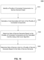
- FIG. 19 is a flowchart of an example process 1900 for determining service links for a data communication network, consistent with the disclosed embodiments.
- the steps associated with this example process is described in relation to a network management system, such as network management system 150 of FIG. 1 .
- a network management system such as network management system 150 of FIG. 1 .
- One of ordinary skill in the art would appreciate that the steps associated with this example process may also be performed by, for example, a processor of the network devices 120 or a server of the data communication network.
- the example process 1900 allows using a reduced number of service links to satisfy the service demands in the data communication network.
- the network management system identifies a plurality of connected components in a service demand graph.
- Each of the connected components is formed by one or more edges and one or more vertices, and the number of edges included in each of the plurality of connected components is less than or equal to a predetermined size threshold.
- a service demand graph is constructed identifying sets of service demands that are candidates for grooming in the data communication network.
- the service demand graph includes a plurality of vertices corresponding to end points of service demands.
- a first vertex corresponding to first service demand is connected with a second vertex corresponding to the second service demand with an edge when the first service demand and the second service demand have a common service demand end point.
- the network management system may determine the connected components based on the service demand graph.
- FIG. 20 is a diagram illustrating a service demand graph 2000 in a data communication network, in accordance with embodiments of the present disclosure.
- the service demands in the data communication network includes ⁇ A, B>, ⁇ A, C>, ⁇ A, D>, ⁇ E, B>, ⁇ E, C>, and ⁇ E, D>.
- a predetermined size threshold is set to two in this example.
- the service demand graph 2000 includes all the end points of the service demands in the data communication network, and the source and destination nodes of a service demand are connected with an edge.
- the source and destination nodes of the service demand ⁇ A, B> are connected by an edge between node A and node B.
- the source and destination nodes of the service demand ⁇ E, B> are connected by an edge between node E and node B.
- the service demands ⁇ A, B> and ⁇ E, B> form a connected component (AB, EB) via the shared node B.
- the connected components with edge-size less than or equal to the predetermined size threshold can be identified.
- the connected components with size equaling one include the edge formed by each service demand, i.e., (AB), (AC), (AD), (EB), (EC), (ED).
- (x, y) denotes an edge between node x and node y.
- the connected components with size equaling two include two connected edges in the service demand graph, i.e., (AB, AC), (AB, AD), (AC, AD), (EB, EC), (EB, ED), (EC, ED), (AB, EB), (AC, EC), (AD, ED).
- the set of connected components with size less than or equal to the predetermined size threshold includes the follows: ⁇ (AB), (AC), (AD), (EB), (EC), (ED), (AB, AC), (AB, AD), (AC, AD), (EB, EC), (EB, ED), (EC, ED), (AB, EB), (AC, EC), (AD, ED) ⁇ .
- the network management system calculates a cost associated with each of the plurality of connected components. For example, costs for the connected components in the service demand graph 2000 may be calculated.
- the cost for the connected component may depend on the number of service links required for the connected component. For example, the cost for connected component (AC) may be higher than the cost for connected component (AB) when the connected component (AC) requires more service links than the connected component (AB).
- the cost for the connected component may also take into account the amount of resources required to satisfy the service demand(s), the capacity of the service links, the quality of service requirements for the service demand(s), or the like.
- Table 6 provides an example cost for the connected components in the service demand graph 2000. Table 6.
- the network management system determines sets of service demands based on the plurality of connected components and the calculated cost by using a set cover algorithm.
- the sets of service demands may be used to determine a plurality of service links for the plurality of service demands in the data communication network.
- the set cover algorithm may include a greedy algorithm or an integer linear programming.
- the set cover algorithm identifies a subset of connected components with the least cost to cover the plurality of service demands in the data communication network. For example, using a set cover algorithm on the connected components listed on Table 6, a set cover ⁇ (AB), (EB, EC), (AC, AD), (EB, ED) ⁇ may be determined, which corresponds to the sets of service demands for determining the service links.
- the set cover covers all service demands in this example network with a total cost of 7.
- the network management system determines sets of service links for the plurality of service demands based on the sets of service demands. For example, the network management system may determine sets of service links used for the set cover ⁇ (AB), (EB, EC), (AC, AD), (EB, ED) ⁇ .
- the service links assigned for each connected component may be predetermined by a network server.
- the sets of service links can be used to satisfy other service demands in the data communication network, such as service demands ⁇ A, C>, ⁇ A, D>, ⁇ E, B>, ⁇ E, C>, and ⁇ E, D>.
- Table 7 shows service links assigned to each connected component in the service demand graph 2000.
- the sets of service links are determined to include the service links assigned to each connected component in the sets of service demands, which are ⁇ r 1 , r 2 , r 3 , r 4 , r 5 , r 7 ⁇ for the sets of demands ⁇ (AB), (EB, EC), (AC, AD), (EB, ED) ⁇ .
- Table 7 Table 7.
- a non-transitory computer-readable storage medium including instructions is also provided, and the instructions may be executed by a device (such as a computer), for performing the above-described methods.
- the non-transitory computer-readable storage medium may be a read-only memory (ROM), a Random Access Memory (RAM), an electrically erasable programmable read-only memory (EEPROM), Programmable Array Logic (PAL), a disk, an optical disc, a Digital Versatile Disc (DVD), and so on.
Landscapes
- Engineering & Computer Science (AREA)
- Computer Networks & Wireless Communication (AREA)
- Signal Processing (AREA)
- Data Mining & Analysis (AREA)
- Data Exchanges In Wide-Area Networks (AREA)
Claims (15)
- Verfahren zum Bereitstellen eines oder mehrerer Wiederherstellungspfade in einem Datenkommunikationsnetzwerk, umfassend:Identifizieren eines Fehlers in einem oder mehreren Dienstpfaden des Datenkommunikationsnetzwerks (1110),wobei ein Dienstpfad mindestens eine entsprechende Dienstverbindung umfasst, die den Dienstpfad verwendet;Bestimmen einer oder mehrerer betroffener Dienstverbindungen in dem Datenkommunikationsnetzwerk basierend auf dem identifizierten Fehler und einer ersten Datenstruktur (1 120), wobei die erste Datenstruktur eine Vielzahl von Dienstpfaden beinhaltet und die erste Datenstruktur für jeden der Dienstpfade jede von einer oder mehreren Dienstverbindungen in dem Datenkommunikationsnetzwerk angibt, die die Vielzahl von Dienstpfaden verwenden;Bestimmen einer oder mehrerer betroffener Dienstanforderungen basierend auf der betroffenen Dienstverbindungen und einer zweiten Datenstruktur (1130),wobei die zweite Datenstruktur eine Vielzahl von Dienstverbindungen beinhaltet, die von dem Datenkommunikationsnetzwerk bereitgestellt werden, und die zweite Datenstruktur für jede der Dienstverbindungen jede von einer oder mehreren Dienstanforderungen in dem Datenkommunikationsnetzwerk angibt, die durch Verwendung der Vielzahl von Dienstverbindungen erfüllt werden können, und wobei sich die zweite Datenstruktur von der ersten Datenstruktur unterscheidet,wobei die eine oder die mehreren Dienstanforderungen in der zweiten Datenstruktur einen Dienst erfordern, der von einem ersten Dienstknoten zu einem zweiten Dienstknoten geliefert wird;für jede der betroffenen Dienstanforderungen, Bestimmen einer oder mehrerer zulässiger Dienstverbindungen durch Entfernen der betroffenen Dienstverbindungen aus einem Satz entsprechender Dienstverbindungen für die betroffenen Dienstanforderungen (1140); undfür jede der betroffenen Dienstanforderungen, Bestimmen des einen oder der mehreren Wiederherstellungspfade basierend auf der einen oder den mehreren zulässigen Dienstverbindungen (1150).
- Verfahren nach Anspruch 1, wobei der eine oder die mehreren Wiederherstellungspfade unter Verwendung eines Dijkstra-Algorithmus bestimmt werden.
- Verfahren nach Anspruch 1 oder Anspruch 2, ferner umfassend:
für jede der betroffenen Dienstanforderungen, Erstellen eines Netzwerkgraphen, der eine Vielzahl von Dienstknoten und eine oder mehrere Dienstverbindungen beinhaltet, wobei die betroffenen Dienstverbindungen aus dem Netzwerkgraphen ausgeschlossen sind. - Verfahren nach einem der Ansprüche 1 bis 3, wobei die eine oder die mehreren zulässigen Dienstverbindungen basierend auf einer dritten Datenstruktur bestimmt werden, wobei die dritte Datenstruktur eine Vielzahl von Dienstanforderungen und einen entsprechenden Satz von Dienstverbindungen enthält, die von der Vielzahl von Dienstanforderungen verwendet werden können.
- Verfahren nach Anspruch 4, wobei der eine oder die mehreren Wiederherstellungspfade basierend auf einer vierten Datenstruktur bestimmt werden, wobei die vierte Datenstruktur die Vielzahl der von dem Datenkommunikationsnetzwerk bereitgestellten Dienstverbindungen, einen oder mehrere entsprechende Dienstpfade und eine entsprechende Kostenmetrik beinhaltet.
- Netzverwaltungssystem zum Migrieren einer Vielzahl von Kommunikationsdiensten in einem Datenkommunikationsnetzwerk, das System umfassend:mindestens einen Prozessor; undeinen Speicher zum Speichern von Anweisungen, die von dem mindestens einen Prozessor ausgeführt werden können; wobei der mindestens eine Prozessor zu Folgendem konfiguriert ist: Identifizieren eines Fehlers in einem oder mehreren Dienstpfaden des Datenkommunikationsnetzwerkes, wobei ein Dienstpfad mindestens eine entsprechende Dienstverbindung umfasst, die den Dienstpfad verwendet;Bestimmen einer oder mehrerer betroffener Dienstverbindungen in dem Datenkommunikationsnetzwerk basierend auf dem identifizierten Fehler und einer ersten Datenstruktur, wobei die erste Datenstruktur eine Vielzahl von Dienstpfaden beinhaltet und die erste Datenstruktur für jeden der Dienstpfade jede von einer oder mehreren Dienstverbindungen in dem Datenkommunikationsnetzwerk angibt, die die Vielzahl von Dienstpfaden verwenden;Bestimmen einer oder mehrerer betroffener Dienstanforderungen basierend auf der betroffenen Dienstverbindungen und einer zweiten Datenstruktur,wobei die zweite Datenstruktur eine Vielzahl von Dienstverbindungen beinhaltet, die von dem Datenkommunikationsnetzwerk bereitgestellt werden, und die zweite Datenstruktur für jede der Dienstverbindungen jede von einer oder mehreren Dienstanforderungen in dem Datenkommunikationsnetzwerk angibt, die durch Verwendung der Vielzahl von Dienstverbindungen erfüllt werden können, und wobei sich die zweite Datenstruktur von der ersten Datenstruktur unterscheidet,wobei die eine oder die mehreren Dienstanforderungen in der zweiten Datenstruktur einen Dienst erfordern, der von einem ersten Dienstknoten zu einem zweiten Dienstknoten geliefert wird;für jede der betroffenen Dienstanforderungen, Bestimmen einer oder mehrerer zulässiger Dienstverbindungen durch Entfernen der betroffenen Dienstverbindungen aus einem Satz entsprechender Dienstverbindungen für die betroffenen Dienstanforderungen; undfür jede der betroffenen Dienstanforderungen, Bestimmen des einen oder der mehreren Wiederherstellungspfade basierend auf der einen oder den mehreren zulässigen Dienstverbindungen.
- Netzwerkmanagementsystem nach Anspruch 6, wobei der eine oder die mehreren Wiederherstellungspfade unter Verwendung eines Dijkstra-Algorithmus bestimmt werden.
- Netzwerkmanagementsystem nach Anspruch 6 oder 7, wobei der mindestens eine Prozessor ferner zu Folgendem konfiguriert ist:
für jede der betroffenen Dienstanforderungen, Erstellen eines Netzwerkgraphen, der eine Vielzahl von Dienstknoten und eine oder mehrere Dienstverbindungen beinhaltet, wobei die betroffenen Dienstverbindungen aus dem Netzwerkgraphen ausgeschlossen sind. - Netzwerkmanagementsystem nach einem der Ansprüche 6 bis 8, wobei die eine oder die mehreren zulässigen Dienstverbindungen basierend auf einer dritten Datenstruktur bestimmt werden, wobei die dritte Datenstruktur eine Vielzahl von Dienstanforderungen und einen entsprechenden Satz von Dienstverbindungen enthält, die von der Vielzahl von Dienstanforderungen verwendet werden können.
- Netzwerkmanagementsystem nach Anspruch 9, wobei der eine oder die mehreren Wiederherstellungspfade basierend auf einer vierten Datenstruktur bestimmt werden, wobei die vierte Datenstruktur die Vielzahl der von dem Datenkommunikationsnetzwerk bereitgestellten Dienstverbindungen, einen oder mehrere entsprechende Dienstpfade und eine entsprechende Kostenmetrik beinhaltet.
- Computerlesbares Medium, das einen Satz von Anweisungen speichert, der von mindestens einem Prozessor eines Netzwerkmanagementsystems ausgeführt werden kann, um das Netzwerkmanagementsystem zu veranlassen, Operationen zum Bereitstellen eines oder mehrerer Wiederherstellungspfade in einem Datenkommunikationsnetzwerkwerk durchzuführen, die Operationen umfassend:Identifizieren eines Fehlers in einem oder mehreren Dienstpfaden des Datenkommunikationsnetzwerkes, wobei ein Dienstpfad mindestens eine entsprechende Dienst umfasst, der den Dienstpfad verwendet;Bestimmen einer oder mehrerer betroffener Dienstverbindungen in dem Datenkommunikationsnetzwerk basierend auf dem identifizierten Fehler und einer ersten Datenstruktur, wobei die erste Datenstruktur eine Vielzahl von Dienstpfaden beinhaltet und die erste Datenstruktur für jeden der Dienstpfade jede von einer oder mehreren Dienstverbindungen in dem Datenkommunikationsnetzwerk angibt, die die Vielzahl von Dienstpfaden verwenden;Bestimmen einer oder mehrerer betroffener Dienstanforderungen basierend auf der betroffenen Dienstverbindungen und einer zweiten Datenstruktur,wobei die zweite Datenstruktur eine Vielzahl von Dienstverbindungen beinhaltet, die von dem Datenkommunikationsnetzwerk bereitgestellt werden, und die zweite Datenstruktur für jede der Dienstverbindungen jede von einer oder mehreren Dienstanforderungen in dem Datenkommunikationsnetzwerk angibt, die durch Verwendung der Vielzahl von Dienstverbindungen erfüllt werden können, und wobei sich die zweite Datenstruktur von der ersten Datenstruktur unterscheidet,wobei die eine oder die mehreren Dienstanforderungen in der zweiten Datenstruktur einen Dienst erfordern, der von einem ersten Dienstknoten zu einem zweiten Dienstknoten geliefert wird;für jede der betroffenen Dienstanforderungen, Bestimmen einer oder mehrerer zulässiger Dienstverbindungen durch Entfernen der betroffenen Dienstverbindungen aus einem Satz entsprechender Dienstverbindungen für die betroffenen Dienstanforderungen; undfür jede der betroffenen Dienstanforderungen, Bestimmen des einen oder der mehreren Wiederherstellungspfade basierend auf der einen oder den mehreren zulässigen Dienstverbindungen.
- Computerlesbares Medium nach Anspruch 11, wobei der eine oder die mehreren Wiederherstellungspfade durch Verwendung eines Dijkstra-Algorithmus bestimmt werden.
- Computerlesbares Medium nach Anspruch 11 oder Anspruch 12, wobei die Operationen ferner Folgendes umfassen:
für jede der betroffenen Dienstanforderungen, Erstellen eines Netzwerkgraphen, der eine Vielzahl von Dienstknoten und eine oder mehrere Dienstverbindungen beinhaltet, wobei die betroffenen Dienstverbindungen aus dem Netzwerkgraphen ausgeschlossen sind. - Computerlesbares Medium nach einem der Ansprüche 11 bis 13, wobei die eine oder die mehreren zulässigen Dienstverbindungen basierend auf einer dritten Datenstruktur bestimmt werden, wobei die dritte Datenstruktur eine Vielzahl von Dienstanforderungen und einen entsprechenden Satz von Dienstverbindungen enthält, die von der Vielzahl von Dienstanforderungen verwendet werden können.
- Computerlesbares Medium nach Anspruch 14, wobei der eine oder die mehreren Wiederherstellungspfade basierend auf einer vierten Datenstruktur bestimmt werden, wobei die vierte Datenstruktur die Vielzahl der von dem Datenkommunikationsnetzwerk bereitgestellten Dienstverbindungen, einen oder mehrere entsprechende Dienstpfade und eine entsprechende Kostenmetrik beinhaltet.
Priority Applications (1)
| Application Number | Priority Date | Filing Date | Title |
|---|---|---|---|
| EP20190167.5A EP3754908B1 (de) | 2018-12-17 | 2018-12-17 | Migration von diensten in datenkommunikationsnetzwerken |
Applications Claiming Priority (3)
| Application Number | Priority Date | Filing Date | Title |
|---|---|---|---|
| EP18925058.2A EP3688934B1 (de) | 2018-12-17 | 2018-12-17 | Migration von diensten in datenkommunikationsnetzwerken |
| EP20190167.5A EP3754908B1 (de) | 2018-12-17 | 2018-12-17 | Migration von diensten in datenkommunikationsnetzwerken |
| PCT/IB2018/060210 WO2020128569A1 (en) | 2018-12-17 | 2018-12-17 | Migrating services in data communication networks |
Related Parent Applications (2)
| Application Number | Title | Priority Date | Filing Date |
|---|---|---|---|
| EP18925058.2A Division-Into EP3688934B1 (de) | 2018-12-17 | 2018-12-17 | Migration von diensten in datenkommunikationsnetzwerken |
| EP18925058.2A Division EP3688934B1 (de) | 2018-12-17 | 2018-12-17 | Migration von diensten in datenkommunikationsnetzwerken |
Publications (2)
| Publication Number | Publication Date |
|---|---|
| EP3754908A1 EP3754908A1 (de) | 2020-12-23 |
| EP3754908B1 true EP3754908B1 (de) | 2023-02-15 |
Family
ID=67620811
Family Applications (4)
| Application Number | Title | Priority Date | Filing Date |
|---|---|---|---|
| EP20190166.7A Active EP3754907B1 (de) | 2018-12-17 | 2018-12-17 | Migration von diensten in datenkommunikationsnetzwerken |
| EP20190167.5A Active EP3754908B1 (de) | 2018-12-17 | 2018-12-17 | Migration von diensten in datenkommunikationsnetzwerken |
| EP18925058.2A Active EP3688934B1 (de) | 2018-12-17 | 2018-12-17 | Migration von diensten in datenkommunikationsnetzwerken |
| EP20195591.1A Active EP3771153B1 (de) | 2018-12-17 | 2018-12-17 | Migration von diensten in datenkommunikationsnetzwerken |
Family Applications Before (1)
| Application Number | Title | Priority Date | Filing Date |
|---|---|---|---|
| EP20190166.7A Active EP3754907B1 (de) | 2018-12-17 | 2018-12-17 | Migration von diensten in datenkommunikationsnetzwerken |
Family Applications After (2)
| Application Number | Title | Priority Date | Filing Date |
|---|---|---|---|
| EP18925058.2A Active EP3688934B1 (de) | 2018-12-17 | 2018-12-17 | Migration von diensten in datenkommunikationsnetzwerken |
| EP20195591.1A Active EP3771153B1 (de) | 2018-12-17 | 2018-12-17 | Migration von diensten in datenkommunikationsnetzwerken |
Country Status (3)
| Country | Link |
|---|---|
| US (5) | US10491510B1 (de) |
| EP (4) | EP3754907B1 (de) |
| WO (1) | WO2020128569A1 (de) |
Families Citing this family (10)
| Publication number | Priority date | Publication date | Assignee | Title |
|---|---|---|---|---|
| US10972588B2 (en) * | 2018-06-27 | 2021-04-06 | T-Mobile Usa, Inc. | Micro-level network node failover system |
| JP7347007B2 (ja) * | 2019-08-28 | 2023-09-20 | 富士フイルムビジネスイノベーション株式会社 | 情報処理装置、情報処理システム、及び情報処理プログラム |
| US10721315B1 (en) * | 2019-12-12 | 2020-07-21 | Eci Telecom Ltd. | Developing and implementing migration sequences in data communication networks |
| EP4136808B1 (de) * | 2020-04-13 | 2025-12-03 | ECI Telecom Ltd. | Erfüllung von dienstanforderungen in datenkommunikationsnetzen |
| WO2022034359A1 (en) | 2020-08-12 | 2022-02-17 | Eci Telecom Ltd. | Satisfying a set of services over given network resources |
| CN115473815B (zh) * | 2022-08-23 | 2024-01-19 | 浪潮通信信息系统有限公司 | 基于设备变更的业务迁移系统及方法 |
| US12219305B1 (en) | 2023-01-03 | 2025-02-04 | Eci Telecom Ltd. | Optical communication network configuration |
| US11901936B1 (en) * | 2023-01-11 | 2024-02-13 | Eci Telecom Ltd. | Optical communication network configuration |
| US12328139B2 (en) * | 2023-01-11 | 2025-06-10 | Eci Telecom Ltd. | Optical communication network configuration |
| US11888723B1 (en) * | 2023-01-13 | 2024-01-30 | Eci Telecom Ltd. | Communication network configuration |
Family Cites Families (34)
| Publication number | Priority date | Publication date | Assignee | Title |
|---|---|---|---|---|
| US6498778B1 (en) * | 1998-12-17 | 2002-12-24 | At&T Corp. | Optimizing restoration capacity |
| US6996065B2 (en) * | 2000-07-06 | 2006-02-07 | Lucent Technologies Inc. | Dynamic backup routing of network tunnel paths for local restoration in a packet network |
| EP1325594A2 (de) * | 2000-10-10 | 2003-07-09 | Radiant Networks Plc | Vermaschte netzwerke |
| US7391732B1 (en) * | 2002-08-05 | 2008-06-24 | At&T Corp. | Scheme for randomized selection of equal cost links during restoration |
| US7242679B1 (en) * | 2002-10-28 | 2007-07-10 | At&T Corp. | Scheme for routing circuits with dynamic self-adjusting link weights in a network |
| US7295510B2 (en) * | 2002-12-17 | 2007-11-13 | At&T Corporation | Method of estimating restoration capacity in a network |
| US7646706B2 (en) * | 2003-03-31 | 2010-01-12 | Alcatel-Lucent Usa Inc. | Restoration time in mesh networks |
| US7643408B2 (en) * | 2003-03-31 | 2010-01-05 | Alcatel-Lucent Usa Inc. | Restoration time in networks |
| US7283741B2 (en) * | 2003-06-06 | 2007-10-16 | Intellambda Systems, Inc. | Optical reroutable redundancy scheme |
| US7957266B2 (en) * | 2004-05-28 | 2011-06-07 | Alcatel-Lucent Usa Inc. | Efficient and robust routing independent of traffic pattern variability |
| US8446815B2 (en) * | 2004-12-22 | 2013-05-21 | Telecommunications Research Laboratories | Failure independent path protection with p-cycles |
| US7406032B2 (en) * | 2005-01-06 | 2008-07-29 | At&T Corporation | Bandwidth management for MPLS fast rerouting |
| US7715716B2 (en) * | 2006-01-23 | 2010-05-11 | Alcatel-Lucent Usa Inc. | Methods and apparatus for optimizing utilization in reconfigurable optical add-drop mulitplexer based ring network |
| US8111618B2 (en) * | 2006-01-27 | 2012-02-07 | Alcatel Lucent | End-to-end service quality using source-routed probes |
| US20080027900A1 (en) * | 2006-07-12 | 2008-01-31 | International Business Machines Corporation | Method and system for optimal selection of targets based on business rules and resource availability |
| CN101281461B (zh) * | 2007-04-04 | 2012-07-04 | 国际商业机器公司 | 用于迁移应用所依赖的系统环境的方法和装置 |
| US8464270B2 (en) * | 2007-11-29 | 2013-06-11 | Red Hat, Inc. | Dependency management with atomic decay |
| US8639667B2 (en) * | 2008-03-03 | 2014-01-28 | At&T Intellectual Property I, L.P. | Generating conditional functional dependencies |
| US8645837B2 (en) * | 2008-11-26 | 2014-02-04 | Red Hat, Inc. | Graphical user interface for managing services in a distributed computing system |
| US8619553B2 (en) * | 2009-01-08 | 2013-12-31 | Ciena Corporation | Methods and systems for mesh restoration based on associated hop designated transit lists |
| US8457107B2 (en) * | 2010-01-12 | 2013-06-04 | Verizon Patent And Licensing Inc. | Method and system for finding shortest paths in ring networks |
| CN104205728B (zh) * | 2012-04-13 | 2018-03-30 | 瑞典爱立信有限公司 | 用于面向连接的网络中的恢复的方法和设备 |
| US9374270B2 (en) * | 2012-06-06 | 2016-06-21 | Juniper Networks, Inc. | Multicast service in virtual networks |
| US9325371B2 (en) * | 2012-12-05 | 2016-04-26 | Eci Telecom Ltd. | Method for managing data transport using crosstalk data |
| EP2797247A1 (de) * | 2013-04-24 | 2014-10-29 | British Telecommunications Public Limited Company | Optische Datenübertragung |
| US10346862B2 (en) * | 2013-10-08 | 2019-07-09 | Accenture Global Solutions Limited | Migration system to migrate users to target services |
| CA2882904C (en) * | 2013-10-08 | 2017-03-07 | Paul J. Bultema | Service provider network migration |
| US9397917B2 (en) * | 2014-01-10 | 2016-07-19 | Huawei Technologies Co., Ltd. | System and method for zoning in software defined networks |
| US11172022B2 (en) * | 2014-02-21 | 2021-11-09 | Hewlett Packard Enterprise Development Lp | Migrating cloud resources |
| US9887878B2 (en) * | 2014-06-06 | 2018-02-06 | Microsoft Technology Licensing, Llc | Dynamic scheduling of network updates |
| US20160299881A1 (en) * | 2015-04-07 | 2016-10-13 | Xerox Corporation | Method and system for summarizing a document |
| US10003867B2 (en) * | 2016-08-31 | 2018-06-19 | Ciena Corporation | Disjoint path computation systems and methods in optical networks |
| US10547563B2 (en) * | 2017-02-03 | 2020-01-28 | Fujitsu Limited | Efficient message forwarding for distributed resource orchestration |
| US10326688B2 (en) * | 2017-05-25 | 2019-06-18 | Nokia Of America Corporation | Method and apparatus for instantiating a path with the minimum number of segments |
-
2018
- 2018-12-17 EP EP20190166.7A patent/EP3754907B1/de active Active
- 2018-12-17 EP EP20190167.5A patent/EP3754908B1/de active Active
- 2018-12-17 WO PCT/IB2018/060210 patent/WO2020128569A1/en not_active Ceased
- 2018-12-17 EP EP18925058.2A patent/EP3688934B1/de active Active
- 2018-12-17 EP EP20195591.1A patent/EP3771153B1/de active Active
-
2019
- 2019-01-15 US US16/248,351 patent/US10491510B1/en active Active
- 2019-01-15 US US16/248,406 patent/US10389584B1/en active Active
- 2019-01-15 US US16/248,375 patent/US10498590B1/en active Active
- 2019-01-15 US US16/248,304 patent/US11621887B2/en active Active
- 2019-08-15 US US16/542,042 patent/US10581679B1/en active Active
Also Published As
| Publication number | Publication date |
|---|---|
| EP3754907B1 (de) | 2025-05-14 |
| EP3688934A1 (de) | 2020-08-05 |
| US20200195730A1 (en) | 2020-06-18 |
| WO2020128569A1 (en) | 2020-06-25 |
| US10491510B1 (en) | 2019-11-26 |
| EP3688934B1 (de) | 2023-08-09 |
| EP3754907A1 (de) | 2020-12-23 |
| EP3688934A4 (de) | 2020-08-05 |
| US11621887B2 (en) | 2023-04-04 |
| EP3771153C0 (de) | 2023-06-07 |
| US10389584B1 (en) | 2019-08-20 |
| US10498590B1 (en) | 2019-12-03 |
| EP3771153B1 (de) | 2023-06-07 |
| EP3754908A1 (de) | 2020-12-23 |
| US10581679B1 (en) | 2020-03-03 |
| EP3688934C0 (de) | 2023-08-09 |
| EP3771153A1 (de) | 2021-01-27 |
Similar Documents
| Publication | Publication Date | Title |
|---|---|---|
| EP3754908B1 (de) | Migration von diensten in datenkommunikationsnetzwerken | |
| US10721315B1 (en) | Developing and implementing migration sequences in data communication networks | |
| EP4136808B1 (de) | Erfüllung von dienstanforderungen in datenkommunikationsnetzen | |
| US11108873B1 (en) | Determining service links in data communication network | |
| US10003522B2 (en) | Routing with flow over shared risk link groups | |
| US12413507B2 (en) | Satisfying demands in data communications networks | |
| US11611485B1 (en) | Shared risk link group-disjoint routing in data communication networks | |
| US12526196B2 (en) | Preplan assignment generation | |
| EP4401378A1 (de) | Kommunikationsnetzkonfiguration | |
| US11888723B1 (en) | Communication network configuration | |
| US11901936B1 (en) | Optical communication network configuration | |
| US12289230B1 (en) | Communication network configuration | |
| US20240396826A1 (en) | Communication network configuration | |
| US12328139B2 (en) | Optical communication network configuration |
Legal Events
| Date | Code | Title | Description |
|---|---|---|---|
| PUAI | Public reference made under article 153(3) epc to a published international application that has entered the european phase |
Free format text: ORIGINAL CODE: 0009012 |
|
| STAA | Information on the status of an ep patent application or granted ep patent |
Free format text: STATUS: THE APPLICATION HAS BEEN PUBLISHED |
|
| AC | Divisional application: reference to earlier application |
Ref document number: 3688934 Country of ref document: EP Kind code of ref document: P |
|
| AK | Designated contracting states |
Kind code of ref document: A1 Designated state(s): AL AT BE BG CH CY CZ DE DK EE ES FI FR GB GR HR HU IE IS IT LI LT LU LV MC MK MT NL NO PL PT RO RS SE SI SK SM TR |
|
| AX | Request for extension of the european patent |
Extension state: BA ME |
|
| STAA | Information on the status of an ep patent application or granted ep patent |
Free format text: STATUS: REQUEST FOR EXAMINATION WAS MADE |
|
| 17P | Request for examination filed |
Effective date: 20210623 |
|
| RBV | Designated contracting states (corrected) |
Designated state(s): AL AT BE BG CH CY CZ DE DK EE ES FI FR GB GR HR HU IE IS IT LI LT LU LV MC MK MT NL NO PL PT RO RS SE SI SK SM TR |
|
| REG | Reference to a national code |
Ref country code: DE Ref legal event code: R079 Ref document number: 602018046320 Country of ref document: DE Free format text: PREVIOUS MAIN CLASS: H04L0012240000 Ipc: H04L0041120000 |
|
| RIC1 | Information provided on ipc code assigned before grant |
Ipc: H04L 41/0668 20220101ALN20220729BHEP Ipc: H04L 41/0663 20220101ALN20220729BHEP Ipc: H04L 41/0654 20220101ALN20220729BHEP Ipc: H04L 41/0873 20220101ALN20220729BHEP Ipc: H04L 41/14 20220101ALI20220729BHEP Ipc: H04L 41/5019 20220101ALI20220729BHEP Ipc: H04L 41/0813 20220101ALI20220729BHEP Ipc: H04L 41/12 20220101AFI20220729BHEP |
|
| GRAP | Despatch of communication of intention to grant a patent |
Free format text: ORIGINAL CODE: EPIDOSNIGR1 |
|
| STAA | Information on the status of an ep patent application or granted ep patent |
Free format text: STATUS: GRANT OF PATENT IS INTENDED |
|
| INTG | Intention to grant announced |
Effective date: 20220919 |
|
| GRAS | Grant fee paid |
Free format text: ORIGINAL CODE: EPIDOSNIGR3 |
|
| GRAA | (expected) grant |
Free format text: ORIGINAL CODE: 0009210 |
|
| STAA | Information on the status of an ep patent application or granted ep patent |
Free format text: STATUS: THE PATENT HAS BEEN GRANTED |
|
| AC | Divisional application: reference to earlier application |
Ref document number: 3688934 Country of ref document: EP Kind code of ref document: P |
|
| AK | Designated contracting states |
Kind code of ref document: B1 Designated state(s): AL AT BE BG CH CY CZ DE DK EE ES FI FR GB GR HR HU IE IS IT LI LT LU LV MC MK MT NL NO PL PT RO RS SE SI SK SM TR |
|
| REG | Reference to a national code |
Ref country code: CH Ref legal event code: EP Ref country code: GB Ref legal event code: FG4D |
|
| REG | Reference to a national code |
Ref country code: DE Ref legal event code: R096 Ref document number: 602018046320 Country of ref document: DE |
|
| REG | Reference to a national code |
Ref country code: AT Ref legal event code: REF Ref document number: 1548836 Country of ref document: AT Kind code of ref document: T Effective date: 20230315 Ref country code: IE Ref legal event code: FG4D |
|
| REG | Reference to a national code |
Ref country code: LT Ref legal event code: MG9D |
|
| REG | Reference to a national code |
Ref country code: NL Ref legal event code: MP Effective date: 20230215 |
|
| REG | Reference to a national code |
Ref country code: AT Ref legal event code: MK05 Ref document number: 1548836 Country of ref document: AT Kind code of ref document: T Effective date: 20230215 |
|
| PG25 | Lapsed in a contracting state [announced via postgrant information from national office to epo] |
Ref country code: RS Free format text: LAPSE BECAUSE OF FAILURE TO SUBMIT A TRANSLATION OF THE DESCRIPTION OR TO PAY THE FEE WITHIN THE PRESCRIBED TIME-LIMIT Effective date: 20230215 Ref country code: PT Free format text: LAPSE BECAUSE OF FAILURE TO SUBMIT A TRANSLATION OF THE DESCRIPTION OR TO PAY THE FEE WITHIN THE PRESCRIBED TIME-LIMIT Effective date: 20230615 Ref country code: NO Free format text: LAPSE BECAUSE OF FAILURE TO SUBMIT A TRANSLATION OF THE DESCRIPTION OR TO PAY THE FEE WITHIN THE PRESCRIBED TIME-LIMIT Effective date: 20230515 Ref country code: NL Free format text: LAPSE BECAUSE OF FAILURE TO SUBMIT A TRANSLATION OF THE DESCRIPTION OR TO PAY THE FEE WITHIN THE PRESCRIBED TIME-LIMIT Effective date: 20230215 Ref country code: LV Free format text: LAPSE BECAUSE OF FAILURE TO SUBMIT A TRANSLATION OF THE DESCRIPTION OR TO PAY THE FEE WITHIN THE PRESCRIBED TIME-LIMIT Effective date: 20230215 Ref country code: LT Free format text: LAPSE BECAUSE OF FAILURE TO SUBMIT A TRANSLATION OF THE DESCRIPTION OR TO PAY THE FEE WITHIN THE PRESCRIBED TIME-LIMIT Effective date: 20230215 Ref country code: HR Free format text: LAPSE BECAUSE OF FAILURE TO SUBMIT A TRANSLATION OF THE DESCRIPTION OR TO PAY THE FEE WITHIN THE PRESCRIBED TIME-LIMIT Effective date: 20230215 Ref country code: ES Free format text: LAPSE BECAUSE OF FAILURE TO SUBMIT A TRANSLATION OF THE DESCRIPTION OR TO PAY THE FEE WITHIN THE PRESCRIBED TIME-LIMIT Effective date: 20230215 Ref country code: AT Free format text: LAPSE BECAUSE OF FAILURE TO SUBMIT A TRANSLATION OF THE DESCRIPTION OR TO PAY THE FEE WITHIN THE PRESCRIBED TIME-LIMIT Effective date: 20230215 |
|
| P01 | Opt-out of the competence of the unified patent court (upc) registered |
Effective date: 20230725 |
|
| PG25 | Lapsed in a contracting state [announced via postgrant information from national office to epo] |
Ref country code: SE Free format text: LAPSE BECAUSE OF FAILURE TO SUBMIT A TRANSLATION OF THE DESCRIPTION OR TO PAY THE FEE WITHIN THE PRESCRIBED TIME-LIMIT Effective date: 20230215 Ref country code: PL Free format text: LAPSE BECAUSE OF FAILURE TO SUBMIT A TRANSLATION OF THE DESCRIPTION OR TO PAY THE FEE WITHIN THE PRESCRIBED TIME-LIMIT Effective date: 20230215 Ref country code: IS Free format text: LAPSE BECAUSE OF FAILURE TO SUBMIT A TRANSLATION OF THE DESCRIPTION OR TO PAY THE FEE WITHIN THE PRESCRIBED TIME-LIMIT Effective date: 20230615 Ref country code: GR Free format text: LAPSE BECAUSE OF FAILURE TO SUBMIT A TRANSLATION OF THE DESCRIPTION OR TO PAY THE FEE WITHIN THE PRESCRIBED TIME-LIMIT Effective date: 20230516 Ref country code: FI Free format text: LAPSE BECAUSE OF FAILURE TO SUBMIT A TRANSLATION OF THE DESCRIPTION OR TO PAY THE FEE WITHIN THE PRESCRIBED TIME-LIMIT Effective date: 20230215 |
|
| PG25 | Lapsed in a contracting state [announced via postgrant information from national office to epo] |
Ref country code: SM Free format text: LAPSE BECAUSE OF FAILURE TO SUBMIT A TRANSLATION OF THE DESCRIPTION OR TO PAY THE FEE WITHIN THE PRESCRIBED TIME-LIMIT Effective date: 20230215 Ref country code: RO Free format text: LAPSE BECAUSE OF FAILURE TO SUBMIT A TRANSLATION OF THE DESCRIPTION OR TO PAY THE FEE WITHIN THE PRESCRIBED TIME-LIMIT Effective date: 20230215 Ref country code: EE Free format text: LAPSE BECAUSE OF FAILURE TO SUBMIT A TRANSLATION OF THE DESCRIPTION OR TO PAY THE FEE WITHIN THE PRESCRIBED TIME-LIMIT Effective date: 20230215 Ref country code: DK Free format text: LAPSE BECAUSE OF FAILURE TO SUBMIT A TRANSLATION OF THE DESCRIPTION OR TO PAY THE FEE WITHIN THE PRESCRIBED TIME-LIMIT Effective date: 20230215 Ref country code: CZ Free format text: LAPSE BECAUSE OF FAILURE TO SUBMIT A TRANSLATION OF THE DESCRIPTION OR TO PAY THE FEE WITHIN THE PRESCRIBED TIME-LIMIT Effective date: 20230215 |
|
| REG | Reference to a national code |
Ref country code: DE Ref legal event code: R097 Ref document number: 602018046320 Country of ref document: DE |
|
| PG25 | Lapsed in a contracting state [announced via postgrant information from national office to epo] |
Ref country code: SK Free format text: LAPSE BECAUSE OF FAILURE TO SUBMIT A TRANSLATION OF THE DESCRIPTION OR TO PAY THE FEE WITHIN THE PRESCRIBED TIME-LIMIT Effective date: 20230215 |
|
| PLBE | No opposition filed within time limit |
Free format text: ORIGINAL CODE: 0009261 |
|
| STAA | Information on the status of an ep patent application or granted ep patent |
Free format text: STATUS: NO OPPOSITION FILED WITHIN TIME LIMIT |
|
| 26N | No opposition filed |
Effective date: 20231116 |
|
| PG25 | Lapsed in a contracting state [announced via postgrant information from national office to epo] |
Ref country code: SI Free format text: LAPSE BECAUSE OF FAILURE TO SUBMIT A TRANSLATION OF THE DESCRIPTION OR TO PAY THE FEE WITHIN THE PRESCRIBED TIME-LIMIT Effective date: 20230215 |
|
| PG25 | Lapsed in a contracting state [announced via postgrant information from national office to epo] |
Ref country code: IT Free format text: LAPSE BECAUSE OF FAILURE TO SUBMIT A TRANSLATION OF THE DESCRIPTION OR TO PAY THE FEE WITHIN THE PRESCRIBED TIME-LIMIT Effective date: 20230215 |
|
| REG | Reference to a national code |
Ref country code: CH Ref legal event code: PL |
|
| PG25 | Lapsed in a contracting state [announced via postgrant information from national office to epo] |
Ref country code: LU Free format text: LAPSE BECAUSE OF NON-PAYMENT OF DUE FEES Effective date: 20231217 |
|
| PG25 | Lapsed in a contracting state [announced via postgrant information from national office to epo] |
Ref country code: MC Free format text: LAPSE BECAUSE OF FAILURE TO SUBMIT A TRANSLATION OF THE DESCRIPTION OR TO PAY THE FEE WITHIN THE PRESCRIBED TIME-LIMIT Effective date: 20230215 |
|
| REG | Reference to a national code |
Ref country code: BE Ref legal event code: MM Effective date: 20231231 |
|
| PG25 | Lapsed in a contracting state [announced via postgrant information from national office to epo] |
Ref country code: MC Free format text: LAPSE BECAUSE OF FAILURE TO SUBMIT A TRANSLATION OF THE DESCRIPTION OR TO PAY THE FEE WITHIN THE PRESCRIBED TIME-LIMIT Effective date: 20230215 Ref country code: LU Free format text: LAPSE BECAUSE OF NON-PAYMENT OF DUE FEES Effective date: 20231217 |
|
| REG | Reference to a national code |
Ref country code: IE Ref legal event code: MM4A |
|
| PG25 | Lapsed in a contracting state [announced via postgrant information from national office to epo] |
Ref country code: IE Free format text: LAPSE BECAUSE OF NON-PAYMENT OF DUE FEES Effective date: 20231217 |
|
| PG25 | Lapsed in a contracting state [announced via postgrant information from national office to epo] |
Ref country code: BE Free format text: LAPSE BECAUSE OF NON-PAYMENT OF DUE FEES Effective date: 20231231 |
|
| PG25 | Lapsed in a contracting state [announced via postgrant information from national office to epo] |
Ref country code: CH Free format text: LAPSE BECAUSE OF NON-PAYMENT OF DUE FEES Effective date: 20231231 |
|
| PG25 | Lapsed in a contracting state [announced via postgrant information from national office to epo] |
Ref country code: IE Free format text: LAPSE BECAUSE OF NON-PAYMENT OF DUE FEES Effective date: 20231217 Ref country code: CH Free format text: LAPSE BECAUSE OF NON-PAYMENT OF DUE FEES Effective date: 20231231 Ref country code: BE Free format text: LAPSE BECAUSE OF NON-PAYMENT OF DUE FEES Effective date: 20231231 |
|
| PG25 | Lapsed in a contracting state [announced via postgrant information from national office to epo] |
Ref country code: BG Free format text: LAPSE BECAUSE OF FAILURE TO SUBMIT A TRANSLATION OF THE DESCRIPTION OR TO PAY THE FEE WITHIN THE PRESCRIBED TIME-LIMIT Effective date: 20230215 |
|
| PG25 | Lapsed in a contracting state [announced via postgrant information from national office to epo] |
Ref country code: BG Free format text: LAPSE BECAUSE OF FAILURE TO SUBMIT A TRANSLATION OF THE DESCRIPTION OR TO PAY THE FEE WITHIN THE PRESCRIBED TIME-LIMIT Effective date: 20230215 |
|
| PG25 | Lapsed in a contracting state [announced via postgrant information from national office to epo] |
Ref country code: CY Free format text: LAPSE BECAUSE OF FAILURE TO SUBMIT A TRANSLATION OF THE DESCRIPTION OR TO PAY THE FEE WITHIN THE PRESCRIBED TIME-LIMIT; INVALID AB INITIO Effective date: 20181217 |
|
| PG25 | Lapsed in a contracting state [announced via postgrant information from national office to epo] |
Ref country code: HU Free format text: LAPSE BECAUSE OF FAILURE TO SUBMIT A TRANSLATION OF THE DESCRIPTION OR TO PAY THE FEE WITHIN THE PRESCRIBED TIME-LIMIT; INVALID AB INITIO Effective date: 20181217 |
|
| PG25 | Lapsed in a contracting state [announced via postgrant information from national office to epo] |
Ref country code: TR Free format text: LAPSE BECAUSE OF FAILURE TO SUBMIT A TRANSLATION OF THE DESCRIPTION OR TO PAY THE FEE WITHIN THE PRESCRIBED TIME-LIMIT Effective date: 20230215 |
|
| PGFP | Annual fee paid to national office [announced via postgrant information from national office to epo] |
Ref country code: GB Payment date: 20251229 Year of fee payment: 8 |
|
| PGFP | Annual fee paid to national office [announced via postgrant information from national office to epo] |
Ref country code: FR Payment date: 20251226 Year of fee payment: 8 |
|
| PGFP | Annual fee paid to national office [announced via postgrant information from national office to epo] |
Ref country code: DE Payment date: 20251229 Year of fee payment: 8 |