EP3754819A1 - Rotary electric machine - Google Patents
Rotary electric machine Download PDFInfo
- Publication number
- EP3754819A1 EP3754819A1 EP18918483.1A EP18918483A EP3754819A1 EP 3754819 A1 EP3754819 A1 EP 3754819A1 EP 18918483 A EP18918483 A EP 18918483A EP 3754819 A1 EP3754819 A1 EP 3754819A1
- Authority
- EP
- European Patent Office
- Prior art keywords
- stator
- housing
- circumferential surface
- outer circumferential
- electric machine
- Prior art date
- Legal status (The legal status is an assumption and is not a legal conclusion. Google has not performed a legal analysis and makes no representation as to the accuracy of the status listed.)
- Granted
Links
Images




Classifications
-
- H—ELECTRICITY
- H02—GENERATION; CONVERSION OR DISTRIBUTION OF ELECTRIC POWER
- H02K—DYNAMO-ELECTRIC MACHINES
- H02K1/00—Details of the magnetic circuit
- H02K1/06—Details of the magnetic circuit characterised by the shape, form or construction
- H02K1/12—Stationary parts of the magnetic circuit
- H02K1/18—Means for mounting or fastening magnetic stationary parts on to, or to, the stator structures
- H02K1/185—Means for mounting or fastening magnetic stationary parts on to, or to, the stator structures to outer stators
-
- H—ELECTRICITY
- H02—GENERATION; CONVERSION OR DISTRIBUTION OF ELECTRIC POWER
- H02K—DYNAMO-ELECTRIC MACHINES
- H02K5/00—Casings; Enclosures; Supports
- H02K5/24—Casings; Enclosures; Supports specially adapted for suppression or reduction of noise or vibrations
-
- H—ELECTRICITY
- H02—GENERATION; CONVERSION OR DISTRIBUTION OF ELECTRIC POWER
- H02K—DYNAMO-ELECTRIC MACHINES
- H02K1/00—Details of the magnetic circuit
- H02K1/06—Details of the magnetic circuit characterised by the shape, form or construction
- H02K1/12—Stationary parts of the magnetic circuit
- H02K1/20—Stationary parts of the magnetic circuit with channels or ducts for flow of cooling medium
-
- H—ELECTRICITY
- H02—GENERATION; CONVERSION OR DISTRIBUTION OF ELECTRIC POWER
- H02K—DYNAMO-ELECTRIC MACHINES
- H02K5/00—Casings; Enclosures; Supports
- H02K5/04—Casings or enclosures characterised by the shape, form or construction thereof
- H02K5/20—Casings or enclosures characterised by the shape, form or construction thereof with channels or ducts for flow of cooling medium
- H02K5/203—Casings or enclosures characterised by the shape, form or construction thereof with channels or ducts for flow of cooling medium specially adapted for liquids, e.g. cooling jackets
-
- H—ELECTRICITY
- H02—GENERATION; CONVERSION OR DISTRIBUTION OF ELECTRIC POWER
- H02K—DYNAMO-ELECTRIC MACHINES
- H02K9/00—Arrangements for cooling or ventilating
- H02K9/19—Arrangements for cooling or ventilating for machines with closed casing and closed-circuit cooling using a liquid cooling medium, e.g. oil
- H02K9/193—Arrangements for cooling or ventilating for machines with closed casing and closed-circuit cooling using a liquid cooling medium, e.g. oil with provision for replenishing the cooling medium; with means for preventing leakage of the cooling medium
-
- H—ELECTRICITY
- H02—GENERATION; CONVERSION OR DISTRIBUTION OF ELECTRIC POWER
- H02K—DYNAMO-ELECTRIC MACHINES
- H02K1/00—Details of the magnetic circuit
- H02K1/06—Details of the magnetic circuit characterised by the shape, form or construction
- H02K1/12—Stationary parts of the magnetic circuit
- H02K1/18—Means for mounting or fastening magnetic stationary parts on to, or to, the stator structures
Definitions
- the present disclosure relates to a rotary electric machine.
- a turbocharger is known as a device for improving acceleration performance of an engine.
- a time lag (turbo lag) until supercharging is started at the time of acceleration is caused.
- an electric compressor is used as a countermeasure to the above.
- the noise is considered to be made by a vibration of a housing due to a motor.
- the noise can be reduced, as long as a stator can gently be supported against a housing, instead of firmly fixing the stator to the housing.
- Patent Document 1 discloses a motor in which a stator is gently supported against a housing.
- the stator is supported in the axial direction by an expandable member, and the stator is supported in the radial direction by a thermally conductive resin.
- Patent Document 1 JP4092195B
- an object of at least one embodiment of the present disclosure is to provide a rotary electric machine capable of reducing noise with a simple configuration.
- a rotary electric machine includes a housing, a stator disposed in the housing, and at least two support members disposed in at least two different parts, respectively, in an axial direction of the stator between the housing and an outer circumferential surface of the stator, the at least two support members supporting the stator against the housing.
- the at least two support members, the housing, and the outer circumferential surface of the stator form a space.
- the at least two support members are disposed in the two different parts, respectively, in the axial direction of the stator between the housing and the outer circumferential surface of the stator to support the stator against the housing, it is possible to gently support the stator against the housing with the simple configuration. Consequently, a vibration transmitted from the stator to the housing is reduced, making it possible to reduce noise.
- stator is cooled by the cooling fluid flowing in the space formed by the at least two support members, the housing, and the outer circumferential surface of the stator, it is possible to suppress performance degradation due to heat generation by the rotary electric machine.
- the at least two support members are annular seal members separate from the housing and the stator.
- the stator in the above configuration (2) or (3), includes a stator core, and a protective member disposed so as to cover an outer circumferential surface of the stator core, and the outer circumferential surface of the protective member constitutes the outer circumferential surface of the stator.
- the stator core is formed by laminating a plurality of annular steel plates.
- the cooling fluid may leak via a gap between the adjacent steel plates, if the cooling fluid flows in the above-described space.
- the protective member since the outer circumferential surface of the stator core is covered with the protective member, it is possible to prevent the cooling fluid from leaking via the gap between the adjacent steel plates.
- the rotary electric machine further includes a moving constraint mechanism for constraining movement of at least one of the at least two support members in the axial direction of the stator.
- the support members can move freely in the axial direction of the stator, the support members may deviate when the stator is mounted in the housing, taking trouble in installing the support members in appropriate parts respectively, or the support members may move in the axial direction of the stator by a vibration during operation of the rotary electric machine.
- the moving constraint mechanism can constrain the support members in the axial direction of the stator, it is possible to easily mount the stator in the housing or to reduce the movement of the support members due to the vibration during the operation of the rotary electric machine.
- At least one of the at least two support members is a protruding portion formed integrally with one of the housing or the outer circumferential surface of the stator so as to protrude from the one of the housing or the outer circumferential surface of the stator toward the other of the housing or the outer circumferential surface of the stator.
- the support member is formed integrally with the housing or the stator, it is possible to gently support the stator against the housing just by mounting the stator in the housing. Thus, it is possible to improve assembly workability of the rotary electric machine.
- the protruding portion is divided into at least three members to be spaced apart from each other in a circumferential direction of the outer circumferential surface of the stator.
- the support member which is configured such that the protruding portion is divided into the at least three members to be spaced apart from each other in the circumferential direction of the outer circumferential surface of the stator, supports the stator against the housing, it is possible to support the stator more gently than in the case in which the support member composed of the protruding portion of the annular shape is used.
- the at least two support members are disposed in the two different parts, respectively, in the axial direction of the stator between the housing and the outer circumferential surface of the stator to support the stator against the housing, it is possible to gently support the stator against the housing with the simple configuration. Consequently, a vibration transmitted from the stator to the housing is reduced, making it possible to reduce noise.
- FIG. 1 shows a cross-section of an electric compressor 1 including a motor 10 which is a rotary electric machine according to Embodiment 1 of the present disclosure.
- the motor 10 includes a housing 11, a stator 12 supported against the housing 11 with a configuration to be described later in the housing 11, and a rotor 13 disposed to be rotatable with respect to the stator 12 in the housing 11.
- the rotor 13 is fixed to a rotational shaft 14 supported to be rotatable with respect to the housing 11.
- the rotational shaft 14 has one end part 14a protruding outside from the inside of the housing 11.
- An impeller 2 is fixed to the end part 14a of the rotational shaft 14.
- O-rings 15 serving as support members are disposed in two different parts, respectively, in the axial direction of the stator 12.
- Each of the O-rings 15 abuts on the housing 11 and the outer circumferential surface 12a of the stator 12, thereby supporting the stator 12 against the housing 11.
- the two O-rings 15, the housing 11, and the outer circumferential surface 12a of the stator 12 form a space 16 of a cylindrical shape along the circumferential direction of the outer circumferential surface 12a of the stator 12.
- the stator 12 is supported against the housing 11 with the O-rings 15 disposed in the two different parts, respectively, in the axial direction of the stator 12.
- the stator 12 is not firmly fixed to the housing 11, the stator 12 is gently supported against the housing 11, as compared with the above-described comparative configuration.
- the vibration caused by operating the motor 10 is transmitted from the stator 12 to the housing 11 while being damped. That is, since the vibration transmitted from the stator 12 to the housing 11 in the motor 10 is reduced as compared with the vibration transmitted in the above-described comparative configuration, noise is reduced in the motor 10 according to Embodiment 1 as compared with the above-described comparative configuration.
- the O-rings 15 are disposed in the two different parts, respectively, in the axial direction of the stator 12 between the housing 11 and the outer circumferential surface 12a of the stator 12 to support the stator 12 against the housing 11, it is possible to gently support the stator 12 against the housing 11 with the simple configuration. Consequently, since the vibration transmitted from the stator 12 to the housing 11 is reduced, it is possible to reduce noise.
- the two O-rings 15 are provided. However, not less than three O-rings 15 may be provided. If the stator 12 is to be supported only with the one O-ring 15, the stator 12 is inclined with the O-ring 15 as a fulcrum. However, it is possible to gently support the stator 12 against the housing 11 without any inclination by supporting the stator 12 with at least two O-rings 15 in at least two different parts, respectively, in the axial direction of the stator 12.
- the O-rings 15 are used as the support members.
- the space 16 can be sealed in the axial direction of the stator 12, if the annular O-rings 15 are used.
- support members each configured to have a portion partially along the circumferential direction of the outer circumferential surface 12a of the stator 12, for example, C-rings can also be used, if the space 16 need not be sealed.
- Embodiment 2 The rotary electric machine according to Embodiment 2 is obtained by adding, to Embodiment 1, a mechanism for cooling the stator 12.
- Embodiment 2 the same constituent elements as those in Embodiment 1 are associated with the same reference characters and not described again in detail.
- the space 16 is sealed in the axial direction of the stator 12 with the two O-rings 15.
- an inflow passage 5 and an outflow passage 6 are disposed so as to communicate with the space 16.
- a cooling fluid such as water or oil flows in the space 16 via the inflow passage 5 and flows out of the space 16 via the outflow passage 6.
- Other configurations are the same as Embodiment 1.
- Embodiment 2 since the stator 12 is gently supported against the housing 11 with the two O-rings 15, it is possible to obtain an effect of reducing noise as in Embodiment 1.
- the stator 12 since the stator 12 is cooled by the cooling fluid flowing in the space 16, it is possible to suppress performance degradation due to heat generation by the motor 10.
- the space 16 formed by the two O-rings 15, the housing 11, and the outer circumferential surface 12a of the stator 12 is used as a passage for the cooling fluid, there is no need to form a passage for the cooling fluid in the housing 11.
- a stator core 17 of the stator 12 normally has a cylindrical shape formed by laminating a plurality of annular steel plates 18.
- the cooling fluid may leak toward the rotor 13 (see FIG. 2 ) via a gap between the adjacent steel plates 18, if the cooling fluid flows in the space 16 (see FIG. 2 ).
- the stator 12 maybe composed of the stator core 17, and a protective member 19 of a cylindrical shape disposed so as to cover an outer circumferential surface 17a of the stator core 17.
- the protective member 19 it is possible to prevent the cooling fluid flowing in the space 16 from leaking toward the rotor 13 via the gap between the adjacent steel plates 18.
- an outer circumferential surface 19a of the protective member 19 constitutes the outer circumferential surface 12a of the stator 12.
- Embodiment 3 The rotary electric machine according to Embodiment 3 is obtained by adding, to each of Embodiments 1 and 2, a moving constraint mechanism for constraining movement of the O-rings 15 in the axial direction of the stator 12.
- Embodiment 3 will be described below with a configuration obtained by adding the moving constraint mechanism to the configuration of Embodiment 1.
- Embodiment 3 may be configured by adding the moving constraint mechanism to the configuration of Embodiment 2.
- Embodiment 2 the same constituent elements as those in Embodiment 1 are associated with the same reference characters and not described again in detail.
- the motor 10 includes a moving constraint mechanism 20 for constraining movement of the O-rings 15 in the axial direction of the stator 12.
- the moving constraint mechanism 20 is composed of an annular insertion member 21 and an insertion groove 22.
- the insertion member 21 is formed so as to protrude from the outer circumferential surface 12a of the stator 12.
- the insertion groove 22 is formed in the O-ring 15 so as to allow insertion of the insertion member 21.
- the insertion member 21 is inserted into the insertion groove 22, constraining the O-ring 15 in the axial direction of the stator 12.
- Other configurations are the same as Embodiment 1.
- the O-ring 15 can move freely in the axial direction of the stator 12, the O-ring 15 may deviate when the stator 12 is mounted in the housing 11, taking trouble in installing the O-ring 15 in an appropriate part, or the O-ring 15 may move in the axial direction of the stator 12 by the vibration during the operation of the motor 10.
- the moving constraint mechanism 20 can constrain the O-ring 15 in the axial direction of the stator 12, it is possible to easily mount the stator 12 in the housing 11 or to reduce the movement of the O-ring 15 due to the vibration during the operation of the motor 10.
- FIG. 4 is drawn such that only the one O-ring 15 is constrained by the moving constraint mechanism 20 in the axial direction of the stator 12.
- the moving constraint mechanism 20 may be provided to constrain each of the two O-rings 15 in the axial direction of the stator 12.
- the moving constraint mechanism 20 may be provided to constrain all the two O-rings 15 in the axial direction of the stator 12, or the moving constraint mechanism 20 may be provided to constrain some of the O-rings 15 in the axial direction of the stator 12.
- the moving constraint mechanism 20 is composed of the insertion member 21 formed in the stator 12 and the insertion groove 22 formed in the O-ring 15.
- the present invention is not limited to this configuration.
- the moving constraint mechanism 20 maybe composed of an accommodation groove 23 capable of accommodating the O-ring 15 formed along the circumferential direction of the outer circumferential surface 12a of the stator 12. Since the O-ring 15 is accommodated in the accommodation groove 23, it is possible to constrain the O-ring 15 in the axial direction of the stator 12. With this configuration, it is possible to configure the moving constraint mechanism 20 only by forming the accommodation groove 23 in the outer circumferential surface 12a of the stator 12.
- Embodiment 4 The rotary electric machine according to Embodiment 4 is obtained by modifying Embodiment 1 in the configuration of the support member.
- Embodiment 4 the same constituent elements as those in Embodiment 1 are associated with the same reference characters and not described again in detail.
- each of two support members ( FIG. 6 illustrates only one support member) for supporting the stator 12 against the housing 11 is a protruding portion 30 of an annular shape formed integrally with the housing 11 so as to protrude toward the outer circumferential surface 12a of the stator 12 from the housing 11.
- the outer circumferential surface 12a of the stator 12 abuts on the protruding portion 30, thereby supporting the stator 12 against the housing 11.
- Other configurations are the same as Embodiment 1.
- the protruding portions 30 are formed integrally with the housing 11.
- the protruding portions 30 may be formed integrally with the stator 12 so as to protrude from the outer circumferential surface 12a of the stator 12 toward the housing 11.
- both the two support members are the protruding portions 30.
- one of the support member may be the protruding portion 30, and the other may be a support member separate from the housing 11 and the stator, such as the O-ring 15 (see FIG. 1 ).
- at least one of the support members may be the protruding portion 30.
- some of the protruding portions 30 may be formed integrally with the housing 11, and the rest of the protruding portions 30 may be formed integrally with the stator 12.
- the protruding portions 30 each have the annular shape.
- the present invention is not limited to this shape.
- the protruding portion 30 may be configured to be divided into three members 30a, 30b, 30c to be spaced apart from each other in the circumferential direction of the outer circumferential surface 12a of the stator 12. With the above configuration, it is possible to support the stator 12 more gently than in the case in which the support member composed of protruding portion 30 of the annular shape is used.
- the protruding portion 30 may be configured to be divided into not less than four members.
- the rotary electric machine is described as the motor 10 for the electric compressor 1.
- the rotary electric machine may be of any form, as long as the rotary electric machine is configured such that the stator is supported against the housing in the housing.
- the rotary electric machine may be a generator or a motor used for any usage.
Landscapes
- Engineering & Computer Science (AREA)
- Power Engineering (AREA)
- Motor Or Generator Frames (AREA)
- Iron Core Of Rotating Electric Machines (AREA)
- Motor Or Generator Cooling System (AREA)
Abstract
Description
- The present disclosure relates to a rotary electric machine.
- A turbocharger is known as a device for improving acceleration performance of an engine. However, in the turbocharger, a time lag (turbo lag) until supercharging is started at the time of acceleration is caused. As a countermeasure to the above, an electric compressor is used.
- As one of problems of the electric compressor, noise is given. The noise is considered to be made by a vibration of a housing due to a motor. Thus, it is considered that the noise can be reduced, as long as a stator can gently be supported against a housing, instead of firmly fixing the stator to the housing.
-
Patent Document 1 discloses a motor in which a stator is gently supported against a housing. In the motor, the stator is supported in the axial direction by an expandable member, and the stator is supported in the radial direction by a thermally conductive resin. - Patent Document 1:
JP4092195B - However, in the motor described in
Patent Document 1, the problem arises in that there are many support parts, as well as the shape of the expandable member is complicated. - In view of the above, an object of at least one embodiment of the present disclosure is to provide a rotary electric machine capable of reducing noise with a simple configuration.
- (1) A rotary electric machine according to at least one embodiment of the present invention includes a housing, a stator disposed in the housing, and at least two support members disposed in at least two different parts, respectively, in an axial direction of the stator between the housing and an outer circumferential surface of the stator, the at least two support members supporting the stator against the housing. The at least two support members, the housing, and the outer circumferential surface of the stator form a space.
- With the above configuration (1), since the at least two support members are disposed in the two different parts, respectively, in the axial direction of the stator between the housing and the outer circumferential surface of the stator to support the stator against the housing, it is possible to gently support the stator against the housing with the simple configuration. Consequently, a vibration transmitted from the stator to the housing is reduced, making it possible to reduce noise.
- (2) In some embodiments, in the above configuration (1), a cooling fluid flows in the space.
- With the above configuration (2), since the stator is cooled by the cooling fluid flowing in the space formed by the at least two support members, the housing, and the outer circumferential surface of the stator, it is possible to suppress performance degradation due to heat generation by the rotary electric machine.
- (3) In some embodiments, in the above configuration (2), the at least two support members are annular seal members separate from the housing and the stator.
- With the above configuration (3), it is possible to reduce leakage of the cooling fluid from the space by the seal members.
- (4) In some embodiments, in the above configuration (2) or (3), the stator includes a stator core, and a protective member disposed so as to cover an outer circumferential surface of the stator core, and the outer circumferential surface of the protective member constitutes the outer circumferential surface of the stator.
- The stator core is formed by laminating a plurality of annular steel plates. Thus, the cooling fluid may leak via a gap between the adjacent steel plates, if the cooling fluid flows in the above-described space. However, with the above configuration (4), since the outer circumferential surface of the stator core is covered with the protective member, it is possible to prevent the cooling fluid from leaking via the gap between the adjacent steel plates.
- (5) In some embodiments, in any one of the above configurations (1) to (4), the rotary electric machine further includes a moving constraint mechanism for constraining movement of at least one of the at least two support members in the axial direction of the stator.
- If the support members can move freely in the axial direction of the stator, the support members may deviate when the stator is mounted in the housing, taking trouble in installing the support members in appropriate parts respectively, or the support members may move in the axial direction of the stator by a vibration during operation of the rotary electric machine. However, with the above configuration (5), since the moving constraint mechanism can constrain the support members in the axial direction of the stator, it is possible to easily mount the stator in the housing or to reduce the movement of the support members due to the vibration during the operation of the rotary electric machine.
- (6) In some embodiments, in the above configuration (1), at least one of the at least two support members is a protruding portion formed integrally with one of the housing or the outer circumferential surface of the stator so as to protrude from the one of the housing or the outer circumferential surface of the stator toward the other of the housing or the outer circumferential surface of the stator.
- With the above configuration (6), since the support member is formed integrally with the housing or the stator, it is possible to gently support the stator against the housing just by mounting the stator in the housing. Thus, it is possible to improve assembly workability of the rotary electric machine.
- (7) In some embodiments, in the above configuration (6), the protruding portion is divided into at least three members to be spaced apart from each other in a circumferential direction of the outer circumferential surface of the stator.
- With the above configuration (7), since the support member, which is configured such that the protruding portion is divided into the at least three members to be spaced apart from each other in the circumferential direction of the outer circumferential surface of the stator, supports the stator against the housing, it is possible to support the stator more gently than in the case in which the support member composed of the protruding portion of the annular shape is used.
- According to at least one embodiment of the present disclosure, since the at least two support members are disposed in the two different parts, respectively, in the axial direction of the stator between the housing and the outer circumferential surface of the stator to support the stator against the housing, it is possible to gently support the stator against the housing with the simple configuration. Consequently, a vibration transmitted from the stator to the housing is reduced, making it possible to reduce noise.
-
-
FIG. 1 is a cross-sectional view of a rotary electric machine according toEmbodiment 1 of the present disclosure. -
FIG. 2 is a cross-sectional view of the rotary electric machine according toEmbodiment 2 of the present disclosure. -
FIG. 3 is a partial cross-sectional view of a modified example of a stator for the rotary electric machine according toEmbodiment 2 of the present disclosure. -
FIG. 4 is a partial cross-sectional view of the rotary electric machine according to Embodiment 3 of the present disclosure. -
FIG. 5 is a partial cross-sectional view of a modified example of the rotary electric machine according to Embodiment 3 of the present disclosure. -
FIG. 6 is a partial cross-sectional view of the rotary electric machine according to Embodiment 4 of the present disclosure. -
FIG. 7 is a partial cross-sectional view of a modified example of the rotary electric machine according to Embodiment 4 of the present disclosure. - Embodiments of the present invention will now be described in detail with reference to the accompanying drawings. However, the scope of the present invention is not limited to the following embodiments. It is intended that dimensions, materials, shapes, relative positions and the like of components described in the embodiments shall be interpreted as illustrative only and not intended to limit the scope of the present invention.
-
FIG. 1 shows a cross-section of anelectric compressor 1 including amotor 10 which is a rotary electric machine according toEmbodiment 1 of the present disclosure. Themotor 10 includes ahousing 11, astator 12 supported against thehousing 11 with a configuration to be described later in thehousing 11, and arotor 13 disposed to be rotatable with respect to thestator 12 in thehousing 11. Therotor 13 is fixed to arotational shaft 14 supported to be rotatable with respect to thehousing 11. Therotational shaft 14 has oneend part 14a protruding outside from the inside of thehousing 11. Animpeller 2 is fixed to theend part 14a of therotational shaft 14. - Between the
housing 11 and an outer circumferential surface 11a of thestator 12, O-rings 15 serving as support members are disposed in two different parts, respectively, in the axial direction of thestator 12. Each of the O-rings 15 abuts on thehousing 11 and the outercircumferential surface 12a of thestator 12, thereby supporting thestator 12 against thehousing 11. The two O-rings 15, thehousing 11, and the outercircumferential surface 12a of thestator 12 form aspace 16 of a cylindrical shape along the circumferential direction of the outercircumferential surface 12a of thestator 12. - In a case of a configuration in which the entire or large part of the outer
circumferential surface 12a of thestator 12 contacts thehousing 11, thereby supporting thestator 12 against the housing 11 (to be referred to as a comparative configuration hereinafter), since thestator 12 is supported so as to be firmly fixed to thehousing 11, a vibration caused by operating themotor 10 tends to be directly transmitted from thestator 12 to thehousing 11 with little damping. Noise is considered to be made due to such vibration transmission to thehousing 11. - By contrast, in the
motor 10 according toEmbodiment 1, thestator 12 is supported against thehousing 11 with the O-rings 15 disposed in the two different parts, respectively, in the axial direction of thestator 12. In this case, since thestator 12 is not firmly fixed to thehousing 11, thestator 12 is gently supported against thehousing 11, as compared with the above-described comparative configuration. Thus, the vibration caused by operating themotor 10 is transmitted from thestator 12 to thehousing 11 while being damped. That is, since the vibration transmitted from thestator 12 to thehousing 11 in themotor 10 is reduced as compared with the vibration transmitted in the above-described comparative configuration, noise is reduced in themotor 10 according toEmbodiment 1 as compared with the above-described comparative configuration. - Thus, since the O-
rings 15 are disposed in the two different parts, respectively, in the axial direction of thestator 12 between thehousing 11 and the outercircumferential surface 12a of thestator 12 to support thestator 12 against thehousing 11, it is possible to gently support thestator 12 against thehousing 11 with the simple configuration. Consequently, since the vibration transmitted from thestator 12 to thehousing 11 is reduced, it is possible to reduce noise. - In
Embodiment 1, the two O-rings 15 are provided. However, not less than three O-rings 15 may be provided. If thestator 12 is to be supported only with the one O-ring 15, thestator 12 is inclined with the O-ring 15 as a fulcrum. However, it is possible to gently support thestator 12 against thehousing 11 without any inclination by supporting thestator 12 with at least two O-rings 15 in at least two different parts, respectively, in the axial direction of thestator 12. - Moreover, in
Embodiment 1, the O-rings 15 are used as the support members. However, the present invention is not limited thereto. Thespace 16 can be sealed in the axial direction of thestator 12, if the annular O-rings 15 are used. However, support members each configured to have a portion partially along the circumferential direction of the outercircumferential surface 12a of thestator 12, for example, C-rings can also be used, if thespace 16 need not be sealed. - Next, the rotary electric machine according to
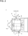
Embodiment 2 will be described. The rotary electric machine according toEmbodiment 2 is obtained by adding, toEmbodiment 1, a mechanism for cooling thestator 12. InEmbodiment 2, the same constituent elements as those inEmbodiment 1 are associated with the same reference characters and not described again in detail. - As shown in
FIG. 2 , thespace 16 is sealed in the axial direction of thestator 12 with the two O-rings 15. In thehousing 11, aninflow passage 5 and anoutflow passage 6 are disposed so as to communicate with thespace 16. A cooling fluid such as water or oil flows in thespace 16 via theinflow passage 5 and flows out of thespace 16 via theoutflow passage 6. Other configurations are the same asEmbodiment 1. - In
Embodiment 2 as well, since thestator 12 is gently supported against thehousing 11 with the two O-rings 15, it is possible to obtain an effect of reducing noise as inEmbodiment 1. In addition, inEmbodiment 2, since thestator 12 is cooled by the cooling fluid flowing in thespace 16, it is possible to suppress performance degradation due to heat generation by themotor 10. Furthermore, inEmbodiment 2, since thespace 16 formed by the two O-rings 15, thehousing 11, and the outercircumferential surface 12a of thestator 12 is used as a passage for the cooling fluid, there is no need to form a passage for the cooling fluid in thehousing 11. Thus, it is possible to simplify the configuration of thehousing 11 and to suppress an increase in manufacturing cost of thehousing 11. - As shown in
FIG. 3 , astator core 17 of thestator 12 normally has a cylindrical shape formed by laminating a plurality ofannular steel plates 18. Thus, the cooling fluid may leak toward the rotor 13 (seeFIG. 2 ) via a gap between theadjacent steel plates 18, if the cooling fluid flows in the space 16 (seeFIG. 2 ). Therefore, thestator 12 maybe composed of thestator core 17, and aprotective member 19 of a cylindrical shape disposed so as to cover an outercircumferential surface 17a of thestator core 17. With theprotective member 19, it is possible to prevent the cooling fluid flowing in thespace 16 from leaking toward therotor 13 via the gap between theadjacent steel plates 18. In this case, an outercircumferential surface 19a of theprotective member 19 constitutes the outercircumferential surface 12a of thestator 12. - Next, the rotary electric machine according to Embodiment 3 will be described. The rotary electric machine according to Embodiment 3 is obtained by adding, to each of
Embodiments rings 15 in the axial direction of thestator 12. Embodiment 3 will be described below with a configuration obtained by adding the moving constraint mechanism to the configuration ofEmbodiment 1. However, Embodiment 3 may be configured by adding the moving constraint mechanism to the configuration ofEmbodiment 2. InEmbodiment 2, the same constituent elements as those inEmbodiment 1 are associated with the same reference characters and not described again in detail. - As shown in
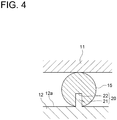
FIG. 4 , the motor 10 (seeFIG. 1 ) includes a movingconstraint mechanism 20 for constraining movement of the O-rings 15 in the axial direction of thestator 12. The movingconstraint mechanism 20 is composed of anannular insertion member 21 and aninsertion groove 22. Theinsertion member 21 is formed so as to protrude from the outercircumferential surface 12a of thestator 12. Theinsertion groove 22 is formed in the O-ring 15 so as to allow insertion of theinsertion member 21. Theinsertion member 21 is inserted into theinsertion groove 22, constraining the O-ring 15 in the axial direction of thestator 12. Other configurations are the same asEmbodiment 1. - If the O-
ring 15 can move freely in the axial direction of thestator 12, the O-ring 15 may deviate when thestator 12 is mounted in thehousing 11, taking trouble in installing the O-ring 15 in an appropriate part, or the O-ring 15 may move in the axial direction of thestator 12 by the vibration during the operation of themotor 10. However, in Embodiment 3, since the movingconstraint mechanism 20 can constrain the O-ring 15 in the axial direction of thestator 12, it is possible to easily mount thestator 12 in thehousing 11 or to reduce the movement of the O-ring 15 due to the vibration during the operation of themotor 10. -
FIG. 4 is drawn such that only the one O-ring 15 is constrained by the movingconstraint mechanism 20 in the axial direction of thestator 12. However, the movingconstraint mechanism 20 may be provided to constrain each of the two O-rings 15 in the axial direction of thestator 12. Moreover, if not less than three O-rings 15 are disposed, the movingconstraint mechanism 20 may be provided to constrain all the two O-rings 15 in the axial direction of thestator 12, or the movingconstraint mechanism 20 may be provided to constrain some of the O-rings 15 in the axial direction of thestator 12. - In Embodiment 3, the moving
constraint mechanism 20 is composed of theinsertion member 21 formed in thestator 12 and theinsertion groove 22 formed in the O-ring 15. However, the present invention is not limited to this configuration. For example, as shown inFIG. 5 , the movingconstraint mechanism 20 maybe composed of anaccommodation groove 23 capable of accommodating the O-ring 15 formed along the circumferential direction of the outercircumferential surface 12a of thestator 12. Since the O-ring 15 is accommodated in theaccommodation groove 23, it is possible to constrain the O-ring 15 in the axial direction of thestator 12. With this configuration, it is possible to configure the movingconstraint mechanism 20 only by forming theaccommodation groove 23 in the outercircumferential surface 12a of thestator 12. Thus, it is possible to simplify the configuration and also to reduce the manufacturing cost of themotor 10, as compared with the movingconstraint mechanism 20 configured as shown inFIG. 4 . In a case in which theprotective member 19 is provided for thestator 12, theinsertion member 21 and theaccommodation groove 23 of the movingconstraint mechanism 20 are formed in theprotective member 19. - Next, the rotary electric machine according to Embodiment 4 will be described. The rotary electric machine according to Embodiment 4 is obtained by modifying
Embodiment 1 in the configuration of the support member. In Embodiment 4, the same constituent elements as those inEmbodiment 1 are associated with the same reference characters and not described again in detail. - As shown in
FIG. 6 , each of two support members (FIG. 6 illustrates only one support member) for supporting thestator 12 against thehousing 11 is a protrudingportion 30 of an annular shape formed integrally with thehousing 11 so as to protrude toward the outercircumferential surface 12a of thestator 12 from thehousing 11. The outercircumferential surface 12a of thestator 12 abuts on the protrudingportion 30, thereby supporting thestator 12 against thehousing 11. Other configurations are the same asEmbodiment 1. - It is also possible to support the
stator 12 against thehousing 11 more gently than in the comparative configuration described inEmbodiment 1 by supporting thestator 12 against thehousing 11 with the two protrudingportions 30 each having the annular shape and formed integrally with thehousing 11. Thus, the vibration transmitted from thestator 12 to thehousing 11 is reduced, making it possible to reduce noise. - Moreover, in Embodiment 4, since the protruding
portions 30 are formed integrally with thehousing 11, it is possible to gently support thestator 12 against thehousing 11 just by mounting thestator 12 in thehousing 11. Thus, it is possible to improve assembly workability of themotor 10. - In Embodiment 4, the protruding
portions 30 are formed integrally with thehousing 11. However, the present invention is not limited to this configuration. The protrudingportions 30 may be formed integrally with thestator 12 so as to protrude from the outercircumferential surface 12a of thestator 12 toward thehousing 11. - In Embodiment 4, both the two support members are the protruding
portions 30. However, one of the support member may be the protrudingportion 30, and the other may be a support member separate from thehousing 11 and the stator, such as the O-ring 15 (seeFIG. 1 ). Moreover, if not less than three support members are provided, at least one of the support members may be the protrudingportion 30. Furthermore, if the plurality of protrudingportions 30 are provided, some of the protrudingportions 30 may be formed integrally with thehousing 11, and the rest of the protrudingportions 30 may be formed integrally with thestator 12. - In Embodiment 4, the protruding
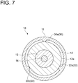
portions 30 each have the annular shape. However, the present invention is not limited to this shape. As shown inFIG. 7 , the protrudingportion 30 may be configured to be divided into threemembers circumferential surface 12a of thestator 12. With the above configuration, it is possible to support thestator 12 more gently than in the case in which the support member composed of protrudingportion 30 of the annular shape is used. The protrudingportion 30 may be configured to be divided into not less than four members. - In each of
Embodiments 1 to 4, the rotary electric machine is described as themotor 10 for theelectric compressor 1. However, the present invention is not limited to this configuration. The rotary electric machine may be of any form, as long as the rotary electric machine is configured such that the stator is supported against the housing in the housing. The rotary electric machine may be a generator or a motor used for any usage. -
- 1
- Electric compressor
- 2
- Impeller
- 5
- Inflow passage
- 6
- Outflow passage
- 10
- Motor
- 11
- Housing
- 12
- Stator
- 12a
- Outer circumferential surface (of stator)
- 13
- Rotor
- 14
- Rotational shaft
- 14a
- End part (of rotational shaft)
- 15
- O-ring (support member)
- 16
- Space
- 17
- Stator core
- 17a
- Outer circumferential surface (of stator core)
- 18
- Steel plate
- 19
- Protective member
- 19a
- Outer circumferential surface (of protective member)
- 20
- Moving constraint mechanism
- 21
- Insertion member
- 22
- Insertion groove
- 23
- Accommodation groove
- 30
- Protruding portion (support member)
- 30a
- Member (composing protruding portion)
- 30b
- Member (composing protruding portion)
- 30c
- Member (composing protruding portion)
Claims (7)
- A rotary electric machine comprising:a housing;a stator disposed in the housing; andat least two support members disposed in at least two different places, respectively, in an axial direction of the stator between the housing and an outer circumferential surface of the stator, the at least two support members supporting the stator against the housing,wherein the at least two support members, the housing, and the outer circumferential surface of the stator form a space.
- The rotary electric machine according to claim 1,
wherein a cooling fluid flows in the space. - The rotary electric machine according to claim 2,
wherein the at least two support members are annular seal members separate from the housing and the stator. - The rotary electric machine according to claim 2 or 3,
wherein the stator includes:a stator core; anda protective member disposed so as to cover an outer circumferential surface of the stator core, andwherein the outer circumferential surface of the protective member constitutes the outer circumferential surface of the stator. - The rotary electric machine according to any one of claims 1 to 4, further comprising a moving constraint mechanism for constraining movement of at least one of the at least two support members in the axial direction of the stator.
- The rotary electric machine according to claim 1,
wherein at least one of the at least two support members is a protruding portion formed integrally with one of the housing or the outer circumferential surface of the stator so as to protrude from the one of the housing or the outer circumferential surface of the stator toward the other of the housing or the outer circumferential surface of the stator. - The rotary electric machine according to claim 6,
wherein the protruding portion is divided into at least three members to be spaced apart from each other in a circumferential direction of the outer circumferential surface of the stator.
Applications Claiming Priority (1)
| Application Number | Priority Date | Filing Date | Title |
|---|---|---|---|
| PCT/JP2018/018677 WO2019220523A1 (en) | 2018-05-15 | 2018-05-15 | Rotary electric machine |
Publications (3)
| Publication Number | Publication Date |
|---|---|
| EP3754819A1 true EP3754819A1 (en) | 2020-12-23 |
| EP3754819A4 EP3754819A4 (en) | 2021-02-24 |
| EP3754819B1 EP3754819B1 (en) | 2022-04-27 |
Family
ID=68539661
Family Applications (1)
| Application Number | Title | Priority Date | Filing Date |
|---|---|---|---|
| EP18918483.1A Active EP3754819B1 (en) | 2018-05-15 | 2018-05-15 | Rotary electric machine |
Country Status (5)
| Country | Link |
|---|---|
| US (1) | US11784517B2 (en) |
| EP (1) | EP3754819B1 (en) |
| JP (1) | JP6955096B2 (en) |
| CN (1) | CN111656650B (en) |
| WO (1) | WO2019220523A1 (en) |
Cited By (1)
| Publication number | Priority date | Publication date | Assignee | Title |
|---|---|---|---|---|
| WO2023186854A1 (en) * | 2022-03-31 | 2023-10-05 | Vitesco Technologies GmbH | Electrical machine |
Families Citing this family (4)
| Publication number | Priority date | Publication date | Assignee | Title |
|---|---|---|---|---|
| US11233445B2 (en) * | 2018-10-11 | 2022-01-25 | The University Of Akron | Acoustic noise mitigation system for an electric machine |
| WO2021261911A1 (en) * | 2020-06-23 | 2021-12-30 | 엘지이노텍 주식회사 | Motor |
| CN119547309A (en) | 2022-09-16 | 2025-02-28 | 株式会社Ihi | Electric supercharger |
| DE102024132759A1 (en) * | 2024-11-11 | 2026-05-13 | Bayerische Motoren Werke Aktiengesellschaft | Stator lamination stack arrangement for a stator of an electric drive machine |
Family Cites Families (17)
| Publication number | Priority date | Publication date | Assignee | Title |
|---|---|---|---|---|
| JPS6166544A (en) * | 1984-09-06 | 1986-04-05 | Toshiba Corp | Vibration and noise suppressor |
| JPS62214285A (en) * | 1986-03-17 | 1987-09-21 | Hitachi Ltd | Closed type compressor |
| DE8800117U1 (en) * | 1988-01-08 | 1988-03-10 | APV-Rosista GmbH, 4750 Unna | Flange connection with a seal |
| JPH0789726B2 (en) * | 1990-03-28 | 1995-09-27 | ファナック株式会社 | Liquid cooling structure of stator |
| JPH07264810A (en) * | 1994-03-17 | 1995-10-13 | Okuma Mach Works Ltd | Liquid-cooled motor |
| GB9809418D0 (en) * | 1998-05-02 | 1998-07-01 | Normalair Garrett Ltd | Electric motor |
| FR2802725B1 (en) * | 1999-12-20 | 2008-06-27 | Denso Corp | ROTARY ELECTRIC MACHINE HAVING AN ELASTIC ARMOR SUPPORT STRUCTURE |
| US6798094B2 (en) | 2000-10-06 | 2004-09-28 | Valeo Equipements Electriques Moteur | Rotary electric machine, and in particular motor vehicle alternator, comprising a stator elastically mounted in a heat-conductive resin |
| JP2004278734A (en) * | 2003-03-18 | 2004-10-07 | Toyota Motor Corp | Sealing device |
| JP2006170379A (en) | 2004-12-17 | 2006-06-29 | Onda Seisakusho Seki Kojo:Kk | Fitting |
| JP2006254530A (en) | 2005-03-08 | 2006-09-21 | Mitsubishi Electric Corp | Electric motor |
| CN101275698B (en) * | 2008-04-29 | 2010-06-02 | 谢红 | Pipe connector |
| CN202266673U (en) * | 2011-10-17 | 2012-06-06 | 北京京东方光电科技有限公司 | Seal device |
| DE102012209589A1 (en) * | 2012-06-06 | 2013-12-12 | Robert Bosch Gmbh | Stator for an electrical machine and assembly that includes the stator |
| JP2015082897A (en) | 2013-10-22 | 2015-04-27 | 日産自動車株式会社 | Rotating electric machine |
| WO2016017370A1 (en) * | 2014-07-31 | 2016-02-04 | アイシン・エィ・ダブリュ株式会社 | Rotating electric machine |
| US10658889B2 (en) * | 2018-09-12 | 2020-05-19 | GM Global Technology Operations LLC | Electromagnetic machine and tunable insert ring |
-
2018
- 2018-05-15 JP JP2020518842A patent/JP6955096B2/en active Active
- 2018-05-15 CN CN201880086969.1A patent/CN111656650B/en active Active
- 2018-05-15 US US17/041,254 patent/US11784517B2/en active Active
- 2018-05-15 WO PCT/JP2018/018677 patent/WO2019220523A1/en not_active Ceased
- 2018-05-15 EP EP18918483.1A patent/EP3754819B1/en active Active
Cited By (1)
| Publication number | Priority date | Publication date | Assignee | Title |
|---|---|---|---|---|
| WO2023186854A1 (en) * | 2022-03-31 | 2023-10-05 | Vitesco Technologies GmbH | Electrical machine |
Also Published As
| Publication number | Publication date |
|---|---|
| US20210013752A1 (en) | 2021-01-14 |
| JPWO2019220523A1 (en) | 2021-04-08 |
| US11784517B2 (en) | 2023-10-10 |
| EP3754819A4 (en) | 2021-02-24 |
| EP3754819B1 (en) | 2022-04-27 |
| WO2019220523A1 (en) | 2019-11-21 |
| CN111656650B (en) | 2023-08-15 |
| CN111656650A (en) | 2020-09-11 |
| JP6955096B2 (en) | 2021-10-27 |
Similar Documents
| Publication | Publication Date | Title |
|---|---|---|
| US11784517B2 (en) | Rotary electric machine with vibration and noise reduction | |
| RU2696857C1 (en) | Electric motor | |
| US10344776B2 (en) | Vibration isolation mount | |
| CN100434720C (en) | Pump with integrated motor and dishwasher with the same | |
| US9848745B2 (en) | Compressor flow path | |
| US3597117A (en) | Fan for narrow environments | |
| EP2945265B1 (en) | Motor equipped with resolver and re-greasable motor with resolver | |
| CN104104163B (en) | Stator-core fixing structure for rotating electric machine | |
| US20180209434A1 (en) | Subsea centrifugal compressor with horizontal shaft and with only one axial thrust bearing | |
| US2489109A (en) | Dynamoelectric machine | |
| CN110999040A (en) | motor | |
| WO2015079550A1 (en) | Rotating machine equipped with shaft sealing device | |
| JP5638696B2 (en) | Compressor and related gas turbine | |
| JP2015019494A (en) | Rotary machine and method of manufacturing the same | |
| JP2015122878A (en) | Rotating electric machine | |
| EP3366956A1 (en) | Sealing device and rotating machine | |
| CN106337698B (en) | Turbine | |
| JPWO2017022007A1 (en) | Rotating electrical machine unit | |
| JP2019047706A (en) | Rotary electric machine, split partition structure, and assembly method for rotary electric machine | |
| US7396206B2 (en) | Arrangement for axially and radially fixing the guide vanes of a vane ring of a gas turbine | |
| EP3387278A1 (en) | Bearing assembly for electrical generator | |
| JP2013201844A (en) | Rotary electric machine | |
| US20140346903A1 (en) | Fan motor | |
| JP2021161884A (en) | Electric pump | |
| KR20030051382A (en) | Rotary electrical machinery |
Legal Events
| Date | Code | Title | Description |
|---|---|---|---|
| STAA | Information on the status of an ep patent application or granted ep patent |
Free format text: STATUS: THE INTERNATIONAL PUBLICATION HAS BEEN MADE |
|
| PUAI | Public reference made under article 153(3) epc to a published international application that has entered the european phase |
Free format text: ORIGINAL CODE: 0009012 |
|
| STAA | Information on the status of an ep patent application or granted ep patent |
Free format text: STATUS: REQUEST FOR EXAMINATION WAS MADE |
|
| 17P | Request for examination filed |
Effective date: 20200917 |
|
| AK | Designated contracting states |
Kind code of ref document: A1 Designated state(s): AL AT BE BG CH CY CZ DE DK EE ES FI FR GB GR HR HU IE IS IT LI LT LU LV MC MK MT NL NO PL PT RO RS SE SI SK SM TR |
|
| AX | Request for extension of the european patent |
Extension state: BA ME |
|
| A4 | Supplementary search report drawn up and despatched |
Effective date: 20210126 |
|
| RIC1 | Information provided on ipc code assigned before grant |
Ipc: H02K 9/19 20060101ALI20210120BHEP Ipc: H02K 5/24 20060101AFI20210120BHEP Ipc: H02K 1/18 20060101ALN20210120BHEP |
|
| STAA | Information on the status of an ep patent application or granted ep patent |
Free format text: STATUS: EXAMINATION IS IN PROGRESS |
|
| DAV | Request for validation of the european patent (deleted) | ||
| DAX | Request for extension of the european patent (deleted) | ||
| 17Q | First examination report despatched |
Effective date: 20210813 |
|
| GRAP | Despatch of communication of intention to grant a patent |
Free format text: ORIGINAL CODE: EPIDOSNIGR1 |
|
| STAA | Information on the status of an ep patent application or granted ep patent |
Free format text: STATUS: GRANT OF PATENT IS INTENDED |
|
| RIC1 | Information provided on ipc code assigned before grant |
Ipc: H02K 1/18 20060101ALN20220110BHEP Ipc: H02K 9/19 20060101ALI20220110BHEP Ipc: H02K 5/24 20060101AFI20220110BHEP |
|
| INTG | Intention to grant announced |
Effective date: 20220128 |
|
| GRAS | Grant fee paid |
Free format text: ORIGINAL CODE: EPIDOSNIGR3 |
|
| GRAA | (expected) grant |
Free format text: ORIGINAL CODE: 0009210 |
|
| STAA | Information on the status of an ep patent application or granted ep patent |
Free format text: STATUS: THE PATENT HAS BEEN GRANTED |
|
| AK | Designated contracting states |
Kind code of ref document: B1 Designated state(s): AL AT BE BG CH CY CZ DE DK EE ES FI FR GB GR HR HU IE IS IT LI LT LU LV MC MK MT NL NO PL PT RO RS SE SI SK SM TR |
|
| REG | Reference to a national code |
Ref country code: GB Ref legal event code: FG4D |
|
| REG | Reference to a national code |
Ref country code: CH Ref legal event code: EP |
|
| REG | Reference to a national code |
Ref country code: AT Ref legal event code: REF Ref document number: 1487733 Country of ref document: AT Kind code of ref document: T Effective date: 20220515 |
|
| REG | Reference to a national code |
Ref country code: DE Ref legal event code: R096 Ref document number: 602018034720 Country of ref document: DE |
|
| REG | Reference to a national code |
Ref country code: IE Ref legal event code: FG4D |
|
| REG | Reference to a national code |
Ref country code: LT Ref legal event code: MG9D |
|
| REG | Reference to a national code |
Ref country code: NL Ref legal event code: MP Effective date: 20220427 |
|
| REG | Reference to a national code |
Ref country code: AT Ref legal event code: MK05 Ref document number: 1487733 Country of ref document: AT Kind code of ref document: T Effective date: 20220427 |
|
| PG25 | Lapsed in a contracting state [announced via postgrant information from national office to epo] |
Ref country code: NL Free format text: LAPSE BECAUSE OF FAILURE TO SUBMIT A TRANSLATION OF THE DESCRIPTION OR TO PAY THE FEE WITHIN THE PRESCRIBED TIME-LIMIT Effective date: 20220427 |
|
| PG25 | Lapsed in a contracting state [announced via postgrant information from national office to epo] |
Ref country code: SE Free format text: LAPSE BECAUSE OF FAILURE TO SUBMIT A TRANSLATION OF THE DESCRIPTION OR TO PAY THE FEE WITHIN THE PRESCRIBED TIME-LIMIT Effective date: 20220427 Ref country code: PT Free format text: LAPSE BECAUSE OF FAILURE TO SUBMIT A TRANSLATION OF THE DESCRIPTION OR TO PAY THE FEE WITHIN THE PRESCRIBED TIME-LIMIT Effective date: 20220829 Ref country code: NO Free format text: LAPSE BECAUSE OF FAILURE TO SUBMIT A TRANSLATION OF THE DESCRIPTION OR TO PAY THE FEE WITHIN THE PRESCRIBED TIME-LIMIT Effective date: 20220727 Ref country code: LT Free format text: LAPSE BECAUSE OF FAILURE TO SUBMIT A TRANSLATION OF THE DESCRIPTION OR TO PAY THE FEE WITHIN THE PRESCRIBED TIME-LIMIT Effective date: 20220427 Ref country code: HR Free format text: LAPSE BECAUSE OF FAILURE TO SUBMIT A TRANSLATION OF THE DESCRIPTION OR TO PAY THE FEE WITHIN THE PRESCRIBED TIME-LIMIT Effective date: 20220427 Ref country code: GR Free format text: LAPSE BECAUSE OF FAILURE TO SUBMIT A TRANSLATION OF THE DESCRIPTION OR TO PAY THE FEE WITHIN THE PRESCRIBED TIME-LIMIT Effective date: 20220728 Ref country code: FI Free format text: LAPSE BECAUSE OF FAILURE TO SUBMIT A TRANSLATION OF THE DESCRIPTION OR TO PAY THE FEE WITHIN THE PRESCRIBED TIME-LIMIT Effective date: 20220427 Ref country code: BG Free format text: LAPSE BECAUSE OF FAILURE TO SUBMIT A TRANSLATION OF THE DESCRIPTION OR TO PAY THE FEE WITHIN THE PRESCRIBED TIME-LIMIT Effective date: 20220727 Ref country code: AT Free format text: LAPSE BECAUSE OF FAILURE TO SUBMIT A TRANSLATION OF THE DESCRIPTION OR TO PAY THE FEE WITHIN THE PRESCRIBED TIME-LIMIT Effective date: 20220427 |
|
| PG25 | Lapsed in a contracting state [announced via postgrant information from national office to epo] |
Ref country code: RS Free format text: LAPSE BECAUSE OF FAILURE TO SUBMIT A TRANSLATION OF THE DESCRIPTION OR TO PAY THE FEE WITHIN THE PRESCRIBED TIME-LIMIT Effective date: 20220427 Ref country code: PL Free format text: LAPSE BECAUSE OF FAILURE TO SUBMIT A TRANSLATION OF THE DESCRIPTION OR TO PAY THE FEE WITHIN THE PRESCRIBED TIME-LIMIT Effective date: 20220427 Ref country code: LV Free format text: LAPSE BECAUSE OF FAILURE TO SUBMIT A TRANSLATION OF THE DESCRIPTION OR TO PAY THE FEE WITHIN THE PRESCRIBED TIME-LIMIT Effective date: 20220427 Ref country code: IS Free format text: LAPSE BECAUSE OF FAILURE TO SUBMIT A TRANSLATION OF THE DESCRIPTION OR TO PAY THE FEE WITHIN THE PRESCRIBED TIME-LIMIT Effective date: 20220827 |
|
| REG | Reference to a national code |
Ref country code: CH Ref legal event code: PL |
|
| REG | Reference to a national code |
Ref country code: BE Ref legal event code: MM Effective date: 20220531 |
|
| REG | Reference to a national code |
Ref country code: DE Ref legal event code: R097 Ref document number: 602018034720 Country of ref document: DE |
|
| PG25 | Lapsed in a contracting state [announced via postgrant information from national office to epo] |
Ref country code: SM Free format text: LAPSE BECAUSE OF FAILURE TO SUBMIT A TRANSLATION OF THE DESCRIPTION OR TO PAY THE FEE WITHIN THE PRESCRIBED TIME-LIMIT Effective date: 20220427 Ref country code: SK Free format text: LAPSE BECAUSE OF FAILURE TO SUBMIT A TRANSLATION OF THE DESCRIPTION OR TO PAY THE FEE WITHIN THE PRESCRIBED TIME-LIMIT Effective date: 20220427 Ref country code: RO Free format text: LAPSE BECAUSE OF FAILURE TO SUBMIT A TRANSLATION OF THE DESCRIPTION OR TO PAY THE FEE WITHIN THE PRESCRIBED TIME-LIMIT Effective date: 20220427 Ref country code: MC Free format text: LAPSE BECAUSE OF FAILURE TO SUBMIT A TRANSLATION OF THE DESCRIPTION OR TO PAY THE FEE WITHIN THE PRESCRIBED TIME-LIMIT Effective date: 20220427 Ref country code: LU Free format text: LAPSE BECAUSE OF NON-PAYMENT OF DUE FEES Effective date: 20220515 Ref country code: LI Free format text: LAPSE BECAUSE OF NON-PAYMENT OF DUE FEES Effective date: 20220531 Ref country code: ES Free format text: LAPSE BECAUSE OF FAILURE TO SUBMIT A TRANSLATION OF THE DESCRIPTION OR TO PAY THE FEE WITHIN THE PRESCRIBED TIME-LIMIT Effective date: 20220427 Ref country code: EE Free format text: LAPSE BECAUSE OF FAILURE TO SUBMIT A TRANSLATION OF THE DESCRIPTION OR TO PAY THE FEE WITHIN THE PRESCRIBED TIME-LIMIT Effective date: 20220427 Ref country code: DK Free format text: LAPSE BECAUSE OF FAILURE TO SUBMIT A TRANSLATION OF THE DESCRIPTION OR TO PAY THE FEE WITHIN THE PRESCRIBED TIME-LIMIT Effective date: 20220427 Ref country code: CZ Free format text: LAPSE BECAUSE OF FAILURE TO SUBMIT A TRANSLATION OF THE DESCRIPTION OR TO PAY THE FEE WITHIN THE PRESCRIBED TIME-LIMIT Effective date: 20220427 Ref country code: CH Free format text: LAPSE BECAUSE OF NON-PAYMENT OF DUE FEES Effective date: 20220531 |
|
| PLBE | No opposition filed within time limit |
Free format text: ORIGINAL CODE: 0009261 |
|
| STAA | Information on the status of an ep patent application or granted ep patent |
Free format text: STATUS: NO OPPOSITION FILED WITHIN TIME LIMIT |
|
| GBPC | Gb: european patent ceased through non-payment of renewal fee |
Effective date: 20220727 |
|
| PG25 | Lapsed in a contracting state [announced via postgrant information from national office to epo] |
Ref country code: AL Free format text: LAPSE BECAUSE OF FAILURE TO SUBMIT A TRANSLATION OF THE DESCRIPTION OR TO PAY THE FEE WITHIN THE PRESCRIBED TIME-LIMIT Effective date: 20220427 |
|
| 26N | No opposition filed |
Effective date: 20230130 |
|
| PG25 | Lapsed in a contracting state [announced via postgrant information from national office to epo] |
Ref country code: IE Free format text: LAPSE BECAUSE OF NON-PAYMENT OF DUE FEES Effective date: 20220515 Ref country code: FR Free format text: LAPSE BECAUSE OF NON-PAYMENT OF DUE FEES Effective date: 20220627 |
|
| PG25 | Lapsed in a contracting state [announced via postgrant information from national office to epo] |
Ref country code: SI Free format text: LAPSE BECAUSE OF FAILURE TO SUBMIT A TRANSLATION OF THE DESCRIPTION OR TO PAY THE FEE WITHIN THE PRESCRIBED TIME-LIMIT Effective date: 20220427 Ref country code: GB Free format text: LAPSE BECAUSE OF NON-PAYMENT OF DUE FEES Effective date: 20220727 Ref country code: BE Free format text: LAPSE BECAUSE OF NON-PAYMENT OF DUE FEES Effective date: 20220531 |
|
| PG25 | Lapsed in a contracting state [announced via postgrant information from national office to epo] |
Ref country code: IT Free format text: LAPSE BECAUSE OF FAILURE TO SUBMIT A TRANSLATION OF THE DESCRIPTION OR TO PAY THE FEE WITHIN THE PRESCRIBED TIME-LIMIT Effective date: 20220427 |
|
| PG25 | Lapsed in a contracting state [announced via postgrant information from national office to epo] |
Ref country code: MK Free format text: LAPSE BECAUSE OF FAILURE TO SUBMIT A TRANSLATION OF THE DESCRIPTION OR TO PAY THE FEE WITHIN THE PRESCRIBED TIME-LIMIT Effective date: 20220427 Ref country code: CY Free format text: LAPSE BECAUSE OF FAILURE TO SUBMIT A TRANSLATION OF THE DESCRIPTION OR TO PAY THE FEE WITHIN THE PRESCRIBED TIME-LIMIT Effective date: 20220427 |
|
| PG25 | Lapsed in a contracting state [announced via postgrant information from national office to epo] |
Ref country code: HU Free format text: LAPSE BECAUSE OF FAILURE TO SUBMIT A TRANSLATION OF THE DESCRIPTION OR TO PAY THE FEE WITHIN THE PRESCRIBED TIME-LIMIT; INVALID AB INITIO Effective date: 20180515 |
|
| PG25 | Lapsed in a contracting state [announced via postgrant information from national office to epo] |
Ref country code: MT Free format text: LAPSE BECAUSE OF FAILURE TO SUBMIT A TRANSLATION OF THE DESCRIPTION OR TO PAY THE FEE WITHIN THE PRESCRIBED TIME-LIMIT Effective date: 20220427 |
|
| PG25 | Lapsed in a contracting state [announced via postgrant information from national office to epo] |
Ref country code: BG Free format text: LAPSE BECAUSE OF FAILURE TO SUBMIT A TRANSLATION OF THE DESCRIPTION OR TO PAY THE FEE WITHIN THE PRESCRIBED TIME-LIMIT Effective date: 20220427 |
|
| PG25 | Lapsed in a contracting state [announced via postgrant information from national office to epo] |
Ref country code: BG Free format text: LAPSE BECAUSE OF FAILURE TO SUBMIT A TRANSLATION OF THE DESCRIPTION OR TO PAY THE FEE WITHIN THE PRESCRIBED TIME-LIMIT Effective date: 20220427 |
|
| PGFP | Annual fee paid to national office [announced via postgrant information from national office to epo] |
Ref country code: DE Payment date: 20250402 Year of fee payment: 8 |
|
| PG25 | Lapsed in a contracting state [announced via postgrant information from national office to epo] |
Ref country code: TR Free format text: LAPSE BECAUSE OF FAILURE TO SUBMIT A TRANSLATION OF THE DESCRIPTION OR TO PAY THE FEE WITHIN THE PRESCRIBED TIME-LIMIT Effective date: 20220427 |