EP3754785B1 - Wide-band flexible radome for microwave antenna - Google Patents
Wide-band flexible radome for microwave antenna Download PDFInfo
- Publication number
- EP3754785B1 EP3754785B1 EP18906409.0A EP18906409A EP3754785B1 EP 3754785 B1 EP3754785 B1 EP 3754785B1 EP 18906409 A EP18906409 A EP 18906409A EP 3754785 B1 EP3754785 B1 EP 3754785B1
- Authority
- EP
- European Patent Office
- Prior art keywords
- radome
- fence
- microwave antenna
- traction
- traction wire
- Prior art date
- Legal status (The legal status is an assumption and is not a legal conclusion. Google has not performed a legal analysis and makes no representation as to the accuracy of the status listed.)
- Active
Links
Images



Classifications
-
- H—ELECTRICITY
- H01—ELECTRIC ELEMENTS
- H01Q—ANTENNAS, i.e. RADIO AERIALS
- H01Q1/00—Details of, or arrangements associated with, antennas
- H01Q1/42—Housings not intimately mechanically associated with radiating elements, e.g. radome
- H01Q1/427—Flexible radomes
-
- H—ELECTRICITY
- H01—ELECTRIC ELEMENTS
- H01Q—ANTENNAS, i.e. RADIO AERIALS
- H01Q19/00—Combinations of primary active antenna elements and units with secondary devices, e.g. with quasi-optical devices, for giving the antenna a desired directional characteristic
- H01Q19/10—Combinations of primary active antenna elements and units with secondary devices, e.g. with quasi-optical devices, for giving the antenna a desired directional characteristic using reflecting surfaces
- H01Q19/18—Combinations of primary active antenna elements and units with secondary devices, e.g. with quasi-optical devices, for giving the antenna a desired directional characteristic using reflecting surfaces having two or more spaced reflecting surfaces
- H01Q19/19—Combinations of primary active antenna elements and units with secondary devices, e.g. with quasi-optical devices, for giving the antenna a desired directional characteristic using reflecting surfaces having two or more spaced reflecting surfaces comprising one main concave reflecting surface associated with an auxiliary reflecting surface
- H01Q19/193—Combinations of primary active antenna elements and units with secondary devices, e.g. with quasi-optical devices, for giving the antenna a desired directional characteristic using reflecting surfaces having two or more spaced reflecting surfaces comprising one main concave reflecting surface associated with an auxiliary reflecting surface with feed supported subreflector
Definitions
- the present invention relates to a radome for a microwave antenna, and particularly, to a flexible radome meeting broadband requirements for a microwave antenna.
- the microwave antenna is an indispensable part of the system.
- the requirement for the performance of antennas is increasingly high, and higher requirements are raised for the user experience and production versatility of microwave antennas.
- a radome is installed outside the antenna, and is a structure for protecting a microwave antenna system from being affected by the external environment.
- the radome is provided mainly for the following purposes.
- the radome of the microwave antenna is generally arranged at a distal end (open end) of a paraboloid of the antenna, and a periphery of the radome is fixed to a fence around the antenna.
- the radome inevitably absorbs and reflects the microwave radiation of the antenna, which affects the electrical performance of the antenna to a certain extent. Therefore, in order to obtain a high-performance antenna, the radome is required to have good electromagnetic wave penetration characteristic in electrical performance, small antenna insertion loss, sufficient strength and durability in mechanical properties, and tolerance to the external harsh environment.
- the radome is usually made of a material having a small dielectric constant, a small loss tangent and high mechanical strength, e.g., glass reinforced plastic, foam, epoxy resin, high molecular polymer, etc.
- the radome generally employs a uniform single wall structure having a concave/convex surface, a sandwich structure, a space skeleton structure, etc.
- a thermoforming method is usually used such that the radome is in different shapes.
- the conventional radome of the existing microwave antenna product usually has a concave or convex taper angle structure made of a rigid material such as special engineering plastic (ABS) by hot press forming to obtain broad radiation characteristics.
- the radome made of the rigid material such as special engineering plastic (ABS) has high mechanical strength, but is usually heavy, large and poor in wave transmission performance.
- the microwave antenna covers multiple frequency bands.
- the thickness specification of the radome designed according to the wavelength cannot be adapted to the multiple frequency bands. If the thickness of the radome is designed according to the working wavelength, the microwave antennas of different frequency bands are bound to employ radomes with different thickness specifications. The difference in the specifications of the radomes for different frequency bands leads to their incompatibility, which not only results in excessive production costs, e.g., the need for multiple production lines, multiple molds, etc., but also increases the risk of wrong mixing during production or assembly.
- the weight of the antenna is inevitably increased due to the influence of the thickness, which is bound to bring a poor experience to a user.
- thermoforming process for forming the concave or convex surface shape of the radome is relatively high in cost, and is disadvantageous for a manufacturer to reduce the operating cost.
- US 2007/182659 A1 describes a radio communication antenna comprising a reflector fitted to a first opening of a cylindrical lateral screen and a radome formed by a flexible material covering a second opening of this lateral screen so as to have a protective surface facing the reflector.
- US 2005/014430 A1 describes a radome comprising flexible composite fabric material including polyester-polyarylate fibers in a flexible resin matrix material.
- EP 3 207 592 A1 describes shroud isolation, including choke shroud isolation, apparatuses for wireless antennas for point-to-point or point-to-multipoint transmission/communication of high bandwidth signals, and integrated reflectors including a shroud or choke shroud.
- the technical problem to be solved by the present invention is to overcome the above defects, and to provide a broadband flexible radome for a microwave antenna, which has the thickness not based on the working wavelength of the antenna, has light weight, small antenna insertion loss and good wave transmission performance, and is universal among multiple frequency bands.
- a broadband flexible radome for a microwave antenna a periphery of which is fixed to a fence arranged around the antenna and is opposite to a reflecting surface of the antenna, wherein the radome is compounded by a high molecular polymer outer layer and a composite fiber textile structural layer mixed with a shielding wave absorbing wire, a tensioning element for connecting a traction mechanism is arranged on a side of the radome facing the reflecting surface of the antenna, the traction mechanism is connected to an inner wall of the fence, and a traction force capable of causing the radome to deform into a concave surface acts on the radome by the tensioning element.
- a reinforcing connecting layer connected with the radome into a whole is arranged on the periphery of the radome.
- a pressing ring with an L-shaped cross section is inverted at an upper end of the fence, and the periphery of the radome is squeezed and fixed to the fence.
- the periphery of the radome is folded to cover the upper end of the fence, a peripheral edge of the radome extends out from a gap between the pressing ring and the fence, and a fixing sheet for limiting the extending portion to pass through the gap between the pressing ring and the fence is fixed on the extending portion of the radome.
- the upper end of the fence is provided with a flange folded down, and the pressing ring is fixed on the flange by a screw or a blind rivet.
- the traction mechanism is a traction wire penetrating through a through hole formed on the tensioning element, and two ends of the traction wire are respectively connected to an inner side wall of the fence.
- the tensioning element is a connecting sheet fixed in a center of the radome, and the connecting sheet is provided with a through hole extending in a diameter direction of the radome.
- an end portion of the traction wire is connected to a pre-tightening screw, one end of the pre-tightening screw penetrates through a connecting hole on a fixing component arranged on an inner side wall of the fence, and a pre-tightening spring is sleeved between a projecting portion of the penetrating end of the pre-tightening screw and the fixing component.
- the end portion of the traction wire penetrates through a connecting hole on a fixing component on an inner side wall of the fence, and the penetrating end of the traction wire is folded backward, and is fixedly connected with a portion of the traction wire not penetrating through the connecting hole by a metal sleeve.
- the end portion of the traction wire is connected to a fixing screw, and the fixing screw penetrates through a connecting hole on a fixing component on an inner side wall of the fence and is fixed by a nut.
- the present invention has the beneficial effects that the radome is formed by compounding a high molecular polymer outer layer and a composite fiber textile structural layer.
- the composite fiber textile structural layer is a main structural material in the radome to increase the strength and bear the force. Because of the high strength of textile fibers, the manufactured radome also has high strength and good durability.
- the shielding wave absorbing wire made of a shielding wave absorbing material is mixed in textile fibers of the composite fiber textile structural layer.
- the shielding wave absorbing wire has certain functions of shielding and absorbing electromagnetic waves, and is compounded with the textile fibers to form the composite fiber textile structural layer. This structure can effectively improve the electrical performance of the radome, reduce the antenna insertion loss, and improve the wave transmission performance.
- the radome of this structure has good wave transmittance, and the thickness selection of the radome does not depend on the working wavelength of the antenna.
- the radome of a uniform thickness low antenna insertion loss can be achieved in multiple frequency bands, the use of a multi-band microwave antenna can be met, the versatility of the radome is realized within a wide frequency range, and the defect of difference of the conventional radome made of ABS and the like in different frequency bands is overcome.
- the radome is made of a flexible material that does not require excessive thickness to have high strength compared with a rigid material, so the radome is relatively thin and light in weight.
- a high molecular polymer is used as the radome outer layer, and the shielding wave absorbing wire is compounded in the composite fiber textile structural layer, so that the radome of the present invention has higher electrical performance and wave transmittance than the general flexible radome.
- the flexible radome of the present invention is recessed to form a concave surface by means of the traction force of the traction mechanism to reduce the return loss of electromagnetic waves on the one hand, and the radome can be tightened by the traction force of the traction mechanism on the other hand.
- the traction mechanism also plays a fixing role to limit the vibration of the radome under the action of wind power, thereby relieving fatigue loss caused by repeated deformation of the radome, and prolonging the service life of the radome.
- the radome has high versatility and good and stable electrical performance in a full frequency range, greatly reduces the weight of the antenna and lowers the production cost of the antenna.
- Reference numerals in the drawings 1 radome, 1-1 reinforcing connecting layer, 2 tensioning element, 2-1 through hole, 3 pressing ring, 4 fence, 4-1 flange, 4-2 screw or blind rivet, 5 fixing component, 5-1 screw or blind rivet, 6 reflecting surface, 7 fixing sheet, 7-1 rivet, 8 back ring, 9 feed source, 10 pre-tightening screw, 10-1 projecting portion, 11 traction mechanism, 12 pre-tightening spring, 13 metal sleeve, 14 fixing screw, and 15 nut.
- a broadband flexible radome for a microwave antenna according to the present invention is an important component for protecting the microwave antenna, and is arranged on a front side of the antenna.
- a periphery of the radome is fixed to a fence 4 arranged around the antenna, and is opposite to a reflecting surface 6 of the antenna.
- the radome 1 used in the microwave antenna according to the present invention is in the form of a cloth-like flexible material.
- the radome 1 of the flexible material is spread on a side opposite to the reflecting surface 6 of the antenna, and a periphery of the radome 1 stretches and is tensioned and fixed to the fence 4 arranged around the reflecting surface of the antenna.
- the fence 4 is used for limiting lateral radiation from the antenna, thereby improving the performance of the antenna.
- the structure and arrangement of the fence 4 are substantially the same as those in the prior art, and the same portions are not described in detail.
- the radome Since the material of the radome is flexible, the radome can be deformed into a desired concave shape by an external force such as pulling. Therefore, unlike the conventional rigid radome made of ABS engineering plastic and the like, thermoforming is not needed, and a production mold can be omitted to reduce the cost.
- the radome according to the present invention is of a flexible multilayer composite structure mainly compounded by a composite fiber textile structural layer and a high molecular polymer outer layer attached to the composite fiber textile structural layer.
- the high molecular polymer outer layer is mainly formed by curing a high molecular polymer coating arranged on the composite fiber textile structural layer, for example, one or more of polymer materials such as polyvinyl chloride, polypropylene and polyamide are used, and the high molecular polymer coating thereof is formed on the composite fiber textile structural layer by hot melting, coating, infiltration, etc., and then is cured to form the high molecular polymer outer layer on the composite fiber textile structural layer.
- the radome is required to have good wave transmission performance, which requires the material to have a small dielectric constant and a small tangent loss, so the specific polymer material can be selected according to the performance parameters.
- the mechanical properties of the material should also be considered. Although stress on the radome is mainly borne by the composite fiber textile structural layer, excellent electrical and mechanical properties can improve the performance and service life of the antenna.
- the composite fiber textile structural layer is a main structural material in the radome to increase the strength and bear the force, and is mainly made of textile fibers (e.g., polyvinyl chloride fibers, etc.) through a textile technology. Since the strength of the textile fibers such as polyvinyl chloride fibers is generally high, the manufactured radome also has high strength and tensile property, can adapt to the influence of the external environment and has good durability.
- textile fibers e.g., polyvinyl chloride fibers, etc.
- the composite fiber textile structural layer of the present invention is different from the general textile fiber cloth.
- Shielding wave absorbing wires made of a shielding wave absorbing material are mixed in the textile fibers of the composite fiber textile structural layer.
- the shielding wave absorbing wires have the function of shielding and absorbing electromagnetic waves, and are structurally compounded with textile fibers such as polyvinyl chloride fibers by interweaving or intertwining among different fibers, or doping of the shielding wave absorbing wires in gaps of the textile fiber structure.
- textile fibers such as polyvinyl chloride fibers by interweaving or intertwining among different fibers, or doping of the shielding wave absorbing wires in gaps of the textile fiber structure.
- the shielding wave absorbing wires are made of a shielding wave absorbing material in the prior art, e.g., carbon black fibers, textile fibers coated with metal micro-powder, silicon carbide fibers, etc., which are not enumerated one by one herein.
- the fiber material of the shielding wave absorbing wires does not need to be too long, as long as it can be compounded with the textile fibers.
- a specific preparation method of the fiber material for the shielding wave absorbing wires and a specific spinning method of the composite fiber textile structural layer can refer to the prior art, and are not described in detail herein.
- the high molecular polymer outer layer and the composite fiber textile structural layer of the radome according to the present invention may further include some auxiliary ingredients added as needed in a specific production process, such as some ingredients for bonding, or ingredients for improving the ultraviolet protection performance, etc.
- auxiliary ingredients added as needed in a specific production process, such as some ingredients for bonding, or ingredients for improving the ultraviolet protection performance, etc.
- the auxiliary ingredients should also be regarded as a part of the high molecular polymer outer layer or the composite fiber textile structural layer.
- the thickness of the radome made of these materials does not depend on the working wavelength of the antenna, and the radome has good versatility in different frequency bands. Therefore, the radome can overcome the defects of high cost, great risk of wrong mixing and the like of the conventional radomes due to many specifications, non-universality and the like.
- the composite flexible radome can be relatively thin, and the overall thickness can be 0.8 mm or less. Hence, the radome is very light in weight, and can reduce the overall weight of the antenna and meet a customer's requirement for lightweight.
- the flexible radome having the electrical performance improved by the shielding wave absorbing wires has relatively small loss in the frequency bands of 6G-26G, can satisfy the broadband versatility, and has the characteristics of light weight and low price.
- the radome of the present invention is flexible, and a desired shape can be formed by assembly, the radome does not to be manufactured by thermoforming as a rigid radome, and the production cost can be reduced.
- the radome 1 After the radome 1 is mounted on the fence 4 around the reflecting surface of the antenna, the radome 1 forms a concave surface by pulling. Specifically, the following structural mode can be used.
- one or more tensioning elements 2 are arranged on a side of the radome 1 facing the reflecting surface 6 of the antenna, and the tensioning elements 2 are fixedly connected with the radome 1 into a whole and connected with a traction mechanism 11 arranged between the radome 1 and the reflecting surfaces 6.
- the traction mechanism 11 pulls the radome 1, and is connected to an inner wall of the fence 4.
- the traction mechanism 11 applies a traction force to the radome 1 via the tensioning elements 2, and the radome 1 is deformed into a concave surface by the traction force to reduce the return loss of electromagnetic waves.
- the traction mechanism 11 may be a traction wire, a draw bar, etc., which is determined according to actual needs.
- the traction mechanism is in the form of traction wires, the assembly of the traction wires is flexible, and the structure is simple and light.
- the traction wires are connected to the tensioning elements 2 of the radome 1, are pulled down such that the radome 1 is recessed to a desired extent, and then fixed to an inner side wall of the fence 4.
- a plurality of traction wires may be symmetrically arranged between the radome 1 and the reflecting surface 6 as needed, and the plurality of traction wires are respectively connected to the tensioning elements 2 on the radome 1.
- the traction wires can be connected to the same tensioning element 2 or different tensioning elements 2 respectively.
- FIG. 1 and FIG. 8 show a preferred embodiment of the present invention, where a traction wire is used as the traction mechanism 11, the traction wire penetrates through a through hole formed on the tensioning element 2, and two ends of the traction wire extend down obliquely to two sides. After the radome 1 is pulled and recessed to the desired extent, the two ends of the traction wire are respectively connected to the inner side wall of the fence 4.
- the traction wire can slide within the through hole of the tensioning element 2, when the radome is pulled down via the two ends of the traction wire, the length of the traction wire on two sides of the through hole can be automatically adjusted by sliding of the traction wire in the through hole, the length of the traction wire on two sides of the tensioning element 2 adapts to the distance from the tensioning element 2 to fixed points of the traction wire on the inner side wall of the fence 4, and the traction wire on the two sides of the through hole applies the same traction force to the tensioning element 2 and the radome 1 to ensure the balanced stress of the radome.
- FIG. 1, 2 and 8 show an embodiment of a tensioning element 2 suitable for a traction wire.
- a main body of the tensioning element 2 is a connecting sheet fixed in a center of the radome 1, and the connecting sheet can be spread and fixedly connected to the radome by gluing, heat sealing, sewing, etc.
- the connecting sheet has a strip projecting portion, the projecting portion is provided with a through hole 2-1 penetrating in the length direction, and the through hole 2-1 extends in the diameter direction of the radome to have a relatively long axial length.
- the tensioning element 2 may also be in the form of a connecting pull ring, a hook or the like, as desired.
- the radome 1 is pulled down to deform into an inward concave surface, and the inclined surface formed by recessing reduces the return loss of electromagnetic waves.
- a fixed part of a peripheral edge of the radome 1 on the fence 4 also needs to bear the force applied by the traction mechanism 11.
- the peripheral edge of the radome 1 needs to be firmly and stably fixed to the fence 4 around the reflecting surface 6 of the antenna, so as not to slip under the pulling force of the traction mechanism 11.
- a reinforcing connecting layer 1 connected with the radome 1 into a whole is arranged at the peripheral edge of the radome 1.
- the reinforcing connecting layer 1-1 may be a folded portion formed by folding the peripheral edge of the radome toward the center, or a layer of the same material as the radome 1 is laminated on the periphery of the radome 1 to form a double-layer structure.
- the periphery with the reinforcing connecting layer 1-1 is fixedly connected with an upper end of the fence 4 to increase the reliability of connection.
- FIG. 4 shows an embodiment of a fixing method of the peripheral edge of the radome 1.
- the periphery of the radome 1 is fixed by a pressing ring 3 with an L-shaped cross section, and the size of the pressing ring 3 is adapted to the size of an upper end of a cylinder formed by the fence 4.
- the pressing ring 3 is inverted at the upper end of the fence 4, wherein one side of the L-shaped cross section of the pressing ring 3 is flush with an upper end surface of the fence 4, and the other side is attached to an outer side of the fence 4.
- the pressing ring 3 is assembled in position and fixedly connected to the fence 4 by a screw or a blind rivet 4-2, and the pressing ring 3 squeezes and fixes the periphery of the radome spread to the upper end of the fence 4 in advance, so as to spread and fix the radome.
- this fixing method has the advantages that the fixing structure is simpler, fewer components are required, and the cost is lower.
- the pressing fixation with the pressing ring 3 is simpler, reduces the labor cost during antenna installation and improves the assembly efficiency.
- the overall size of the radome 1 is larger than the maximum size of the upper end of the cylinder formed by the fence 4, so that the peripheral edge of the radome 1 is spread and extends to the upper end of the fence 4 and then can be further folded down to cover the upper end of the fence 4 from the outer side.
- the folded peripheral edge of the radome 1 extends down in a way of being close to an outer side of the fence 4, and extends out from a gap between the pressing ring 3 and an outer side of the fence 4.
- a fixing sheet 7 is arranged on the extending portion of the radome 1, and the fixing sheet 7 is fixed with the periphery of the radome 1 into a whole by means of a rivet 7-1 or the like.
- the fixing sheet 7 is larger than the gap between the pressing ring 3 and the fence 4. After assembly, the pressing ring 3 can clamp the fixing sheet 7 and restrict the peripheral edge of the radome 1 from passing through the gap.
- fixing sheets 7 are uniformly distributed on the circumferential edge of the radome 1, and are fixed with the radome 1 into a whole by means of rivets 7-1 or the like.
- the pressing ring 3 is inverted at the upper end of the fence 4, and the pressing ring 3 clamps the fixing sheets 7 on the circumference of the radome 1 and presses the fixing sheets 7 down.
- the pressing ring 3 can press the fixing sheets during assembly to facilitate spreading of the radome; and on the other hand, the pressing ring 3 can limit the fixing sheets 7 to prevent the radome from slipping radially under the traction of the traction mechanism 11 or an external force of wind and the like, so as to improve the firmness of fixing the periphery of the radome.
- FIG. 4 further shows a preferred embodiment of the antenna fence 4, where the upper end of the fence 4 is provided with a flange 4-1 folded down, and an upper end surface of the flange 4-1 is a flat surface for connecting and fixing the radome 1 and the pressing ring 3.
- the flange 4-1 increases the size of the upper end surface of the fence 4, and increases a contact surface between the radome 1 and the fence 4, that is, the area of a clamping surface, which is more advantageous for clamping and fixing the periphery of the radome 1 between the pressing ring 3 and the fence 4.
- the pressing ring 3, the radome 1 and the flange 4-1 of the fence 4 can be pre-tightened and connected together by screws or rivets 4-2.
- FIG. 5, 6 and 7 show several specific embodiments of connection of the traction mechanism 11 (e.g., a traction wire) to the inner wall of the fence 4 respectively.
- the traction mechanism 11 e.g., a traction wire
- the traction mechanism 11 is in the form of a traction wire that is connected to the inner side wall of the fence 4 by a pre-tightening screw 10.
- the specific structure is that an end portion of the traction wire penetrates through a hole at one end of the pre-tightening screw 10 and is fixed.
- One end of the pre-tightening screw 10 penetrates through a connecting hole (not shown) formed on a fixing component 5 on the inner side wall of the fence 4, and the pre-tightening screw 10 is movable in the connecting hole and is pre-tightened by a pre-tightening spring 12.
- the fixing component 5 is formed by angle steel which is fixed to the inner side wall of the fence 4 by a screw or a blind rivet 5-1.
- One of two perpendicular plate surfaces of the angle steel is attached to the inner side wall of the fence 4 and fixed by the screw or the blind rivet 5-1.
- the other plate surface of the angle steel is perpendicular to the inner side wall of the fence 4, and is provided with a connecting hole.
- the upper end of the pre-tightening screw 10 is connected to the traction wire, and the lower end penetrates through the connecting hole and is movable up and down in the connecting hole.
- a pre-tightening spring 12 is sleeved on a portion of the pre-tightening screw 10 penetrating through the connecting hole.
- a nut is screwed onto the penetrating end of the pre-tightening screw 10 penetrating through the connecting hole, and the nut forms a projecting portion 10-1 fixed to the pre-tightening screw 10.
- the projecting portion 10-1 can also be formed in other ways, e.g., a projecting component is welded to the pre-tightening screw 10.
- the pre-tightening spring 12 is a compression spring sandwiched between the projecting portion 10-1 of the pre-tightening screw 10 and the fixing component 5 on the inner side wall of the fence 4. Since the fixing component 5 is fixed to the inner side wall of the fence 4, elastic force of the pre-tightening spring 12 is applied downward to the pre-tightening screw 10 via the projecting portion 10-1, and thus a downward elastic pre-tightening force is applied to the traction wire fixed to the upper end of the pre-tightening screw 10 and the radome pulled by the traction wire.
- This embodiment shows an elastic pre-tightening connection form, where the elastic pre-tightening force applied to the traction wire by the pre-tightening spring 12 and the pre-tightening screw 10 can always keep the radome 1 tightened and spread without being relaxed as the service time goes. Therefore, the increase in vibration amplitude under the action of wind power due to the relaxation of the radome 1 can be prevented, fatigue loss caused by repeated deformation of the radome is then relieved, and the service life of the radome is prolonged.
- the traction mechanism 11 in the form of a traction wire used in the above embodiment of the present invention penetrates through the through hole of the tensioning element 2 and is movable in the through hole, the traction wire on two sides of the through hole is equally stressed, and the entire traction wire can be pre-tightened by applying the elastic pre-tightening force on one side.
- the connection of elastic pre-tightening can be only for one end of the traction wire as shown in FIG. 1 , while the other end of the traction wire is in other form of fixed connection.
- the pre-tightening connection of the pre-tightening screw 10 and the pre-tightening spring 12 can also be used at two ends of the traction wire.
- FIG. 6 indicates a fixed connection form of the traction wire.
- a fixing component 5 is also arranged on an inner side wall of the fence 4, and the fixing component 5 can be formed by angle steel fixed to the inner side wall of the fence 4 by a screw or a blind rivet 5-1 according to the embodiment shown in FIG. 5 .
- a connecting hole is also formed on a plate surface of the angle steel perpendicular to the inner side wall of the fence 4.
- the connecting hole may be a threaded hole or an unthreaded hole.
- the traction wire is connected to a fixing screw 14. As shown in FIG. 6 , an end portion of the traction wire passes through a hole at the upper end of the fixing screw 14 and is fixed.
- a lower end of the fixing screw 14 passes through a connecting hole on the fixing component 5 and is directly fixed by a nut.
- this embodiment does not use a pre-tightening spring, but directly uses a nut for fixing. Therefore, the connection is a rigid fixed connection, and does not function as the elastic pre-tightening connection.
- the fixed connection described in this embodiment can be used together with the elastic connection of the pre-tightening screw shown in FIG. 5 .
- the fixed connection shown in this embodiment is used at the other end.
- FIG. 7 gives another form of fixed connection of the traction wire.
- a fixing component 5 also needs to be arranged on an inner side wall of the fence 4, the fixing component 5 can be in the form of the angle steel shown in the above embodiment of FIG. 5 or FIG. 6 , and a plate surface of the angle steel perpendicular to the inner side wall of the fence 4 is provided with a connecting hole.
- the connecting hole is a threading hole, and can be smaller than the connecting hole in the embodiment shown in FIG. 5 or FIG. 6 .
- An end portion of the traction wire penetrates through the connecting hole on the fixing component 5, and the portion of the traction wire penetrating out of the connecting hole (i.e., the penetrating end of the traction wire) is folded backward.
- a metal sleeve 13 is sleeved on the backward-folded penetrating end of the traction wire and the traction wire close to the penetrating end, and then an external force is applied to plastically deform and press the metal sleeve 13, so that the backward-folded end portion of the traction wire is fixedly connected to the portion of the traction wire not penetrating through the connecting hole by the metal sleeve 13 to achieve the function of fixing the traction wire.
- connection described in this embodiment can be used for the connection of two ends of the traction wire, or only for connecting one end of the traction wire, and the other end adopts the connection form shown in FIG. 5 or FIG. 6 .
- FIG. 9 shows another embodiment of the microwave antenna, which is different from the form of the straight cylindrical fence 4 shown in FIG. 1 .
- the fence 4 is inclined and the heights of four sides can be different, so that the radome 1 is arranged obliquely.
- the fixed connection of the radome 1, the tightening of the traction wire and the connection of the end portion of the traction wire as shown in the above embodiments are also applicable to the inclined fence of this embodiment.
- the radome can also be well and stably spread and fixed by the above ways.
- FIG. 10 shows a changing curve of the insertion loss of the microwave antenna using the radome of the present invention along with the frequency.
- the flexible radome has a low insertion loss within the frequency range of 6G-26G, not more than 0.3 dB, and the insertion loss is little affected by the frequency, which can meet the versatility of the broadband microwave antenna.
- the radome of the present invention is compounded by a high molecular polymer outer layer and a composite fiber textile structural layer, shielding wave absorbing wires are compounded in the composite fiber textile structural layer, and this composite structure can effectively improve the electrical performance of the radome, reduce the antenna insertion loss and improve the wave transmission performance.
- the antenna insertion loss of the radome according to the present invention is maintained at a relatively stable low value within a wide frequency range. Compared with the conventional radome, the antenna insertion loss is not greatly increased due to the variation of the frequency band, so the radome is versatile in a relatively wide frequency range.
- the radome of this structure has good wave transmission performance, and the thickness selection of the radome does not depend on the working wavelength of the antenna.
- the radome of a uniform thickness low antenna insertion loss can be achieved in multiple frequency bands, the use of a multi-band microwave antenna can be met, the versatility of the radome is realized within a wide frequency range, and the defect of difference of the conventional radome made of ABS and the like in different frequency bands is overcome.
- the radome is made of a flexible material that does not require excessive thickness to have high strength compared with a rigid material, so the radome is relatively thin and light in weight.
- a high molecular polymer is used as the radome outer layer, and shielding wave absorbing wires are compounded in the composite fiber textile structural layer, so that the radome of the present invention has higher electrical performance and wave transmission performance than the general flexible radome cloth.
- the flexible radome of the present invention is recessed to form a concave surface by means of the traction force of the traction mechanism to reduce the return loss of electromagnetic waves on the one hand, and the radome can be tightened by the traction force of the traction mechanism on the other hand.
- the traction mechanism also plays a fixing role to limit the vibration of the radome under wind power, thereby relieving the fatigue loss caused by repeated deformation of the radome, and prolonging the service life of the radome.
- the radome has high versatility and good and stable electrical performance in a full frequency range, greatly reduces the weight of the antenna and lowers the production cost of the antenna.
Landscapes
- Details Of Aerials (AREA)
Description
- The present invention relates to a radome for a microwave antenna, and particularly, to a flexible radome meeting broadband requirements for a microwave antenna.
- In the conventional point-to-point communication system, the microwave antenna is an indispensable part of the system. In recent years, with the continuous development of the global microwave antenna industry, the requirement for the performance of antennas is increasingly high, and higher requirements are raised for the user experience and production versatility of microwave antennas.
- As an important part of the microwave antenna, a radome is installed outside the antenna, and is a structure for protecting a microwave antenna system from being affected by the external environment. The radome is provided mainly for the following purposes.
- 1. The radome is used to establish a closed area to protect the microwave antenna system from being affected by external natural factors such as wind, rain, ice, snow, dust and solar radiation, thereby maintaining the electrical performance of the microwave antenna stable and reliable, and alleviating the wear, corrosion and aging of the microwave antenna system caused by natural environmental factors such as wind and sunshine to prolong the service life of the microwave antenna.
- 2. The influence of the radome on the shape of the outer contour of the antenna can improve the wind load characteristics of the microwave antenna system to reduce the risk of damage to the antenna system by wind load, and meanwhile maintain the necessary mechanical strength and reduce damage risks caused by conventional installation and accidental impact.
- The radome of the microwave antenna is generally arranged at a distal end (open end) of a paraboloid of the antenna, and a periphery of the radome is fixed to a fence around the antenna. As an obstacle in front of the microwave antenna, the radome inevitably absorbs and reflects the microwave radiation of the antenna, which affects the electrical performance of the antenna to a certain extent. Therefore, in order to obtain a high-performance antenna, the radome is required to have good electromagnetic wave penetration characteristic in electrical performance, small antenna insertion loss, sufficient strength and durability in mechanical properties, and tolerance to the external harsh environment.
- The radome is usually made of a material having a small dielectric constant, a small loss tangent and high mechanical strength, e.g., glass reinforced plastic, foam, epoxy resin, high molecular polymer, etc. Structurally, the radome generally employs a uniform single wall structure having a concave/convex surface, a sandwich structure, a space skeleton structure, etc. In a manufacturing method, a thermoforming method is usually used such that the radome is in different shapes.
- The conventional radome of the existing microwave antenna product usually has a concave or convex taper angle structure made of a rigid material such as special engineering plastic (ABS) by hot press forming to obtain broad radiation characteristics. The radome made of the rigid material such as special engineering plastic (ABS) has high mechanical strength, but is usually heavy, large and poor in wave transmission performance.
- Electrically, in order to minimize the reflection of the radome, increase the gain and reduce the insertion loss value, it is usually necessary to design the uniform single wall thickness of the radome or the sandwich thickness of a sandwich structure according to the working wavelength, and a corresponding half-wavelength medium thickness is usually used such that the radome has good wave transmission performance.
- However, the microwave antenna covers multiple frequency bands. The thickness specification of the radome designed according to the wavelength cannot be adapted to the multiple frequency bands. If the thickness of the radome is designed according to the working wavelength, the microwave antennas of different frequency bands are bound to employ radomes with different thickness specifications. The difference in the specifications of the radomes for different frequency bands leads to their incompatibility, which not only results in excessive production costs, e.g., the need for multiple production lines, multiple molds, etc., but also increases the risk of wrong mixing during production or assembly.
- Moreover, for an individual low-frequency microwave antenna, if the half-wavelength medium thickness is used, the weight of the antenna is inevitably increased due to the influence of the thickness, which is bound to bring a poor experience to a user.
- In addition, a thermoforming process for forming the concave or convex surface shape of the radome is relatively high in cost, and is disadvantageous for a manufacturer to reduce the operating cost.
-
US 2007/182659 A1 describes a radio communication antenna comprising a reflector fitted to a first opening of a cylindrical lateral screen and a radome formed by a flexible material covering a second opening of this lateral screen so as to have a protective surface facing the reflector. -
US 2005/014430 A1 describes a radome comprising flexible composite fabric material including polyester-polyarylate fibers in a flexible resin matrix material. -
EP 3 207 592 A1 describes shroud isolation, including choke shroud isolation, apparatuses for wireless antennas for point-to-point or point-to-multipoint transmission/communication of high bandwidth signals, and integrated reflectors including a shroud or choke shroud. - The technical problem to be solved by the present invention is to overcome the above defects, and to provide a broadband flexible radome for a microwave antenna, which has the thickness not based on the working wavelength of the antenna, has light weight, small antenna insertion loss and good wave transmission performance, and is universal among multiple frequency bands.
- The technical solution adopted by the present invention, which is defined by the appended claims, to solve the above technical problem is: a broadband flexible radome for a microwave antenna, a periphery of which is fixed to a fence arranged around the antenna and is opposite to a reflecting surface of the antenna, wherein the radome is compounded by a high molecular polymer outer layer and a composite fiber textile structural layer mixed with a shielding wave absorbing wire, a tensioning element for connecting a traction mechanism is arranged on a side of the radome facing the reflecting surface of the antenna, the traction mechanism is connected to an inner wall of the fence, and a traction force capable of causing the radome to deform into a concave surface acts on the radome by the tensioning element.
- Further, a reinforcing connecting layer connected with the radome into a whole is arranged on the periphery of the radome.
- Further, a pressing ring with an L-shaped cross section is inverted at an upper end of the fence, and the periphery of the radome is squeezed and fixed to the fence.
- Further, the periphery of the radome is folded to cover the upper end of the fence, a peripheral edge of the radome extends out from a gap between the pressing ring and the fence, and a fixing sheet for limiting the extending portion to pass through the gap between the pressing ring and the fence is fixed on the extending portion of the radome.
- Further, the upper end of the fence is provided with a flange folded down, and the pressing ring is fixed on the flange by a screw or a blind rivet.
- Further, the traction mechanism is a traction wire penetrating through a through hole formed on the tensioning element, and two ends of the traction wire are respectively connected to an inner side wall of the fence.
- Further, the tensioning element is a connecting sheet fixed in a center of the radome, and the connecting sheet is provided with a through hole extending in a diameter direction of the radome.
- Further, an end portion of the traction wire is connected to a pre-tightening screw, one end of the pre-tightening screw penetrates through a connecting hole on a fixing component arranged on an inner side wall of the fence, and a pre-tightening spring is sleeved between a projecting portion of the penetrating end of the pre-tightening screw and the fixing component.
- Further, in another embodiment, the end portion of the traction wire penetrates through a connecting hole on a fixing component on an inner side wall of the fence, and the penetrating end of the traction wire is folded backward, and is fixedly connected with a portion of the traction wire not penetrating through the connecting hole by a metal sleeve.
- Further, the end portion of the traction wire is connected to a fixing screw, and the fixing screw penetrates through a connecting hole on a fixing component on an inner side wall of the fence and is fixed by a nut.
- The present invention has the beneficial effects that the radome is formed by compounding a high molecular polymer outer layer and a composite fiber textile structural layer. The composite fiber textile structural layer is a main structural material in the radome to increase the strength and bear the force. Because of the high strength of textile fibers, the manufactured radome also has high strength and good durability. Unlike the conventional fiber cloth, the shielding wave absorbing wire made of a shielding wave absorbing material is mixed in textile fibers of the composite fiber textile structural layer. The shielding wave absorbing wire has certain functions of shielding and absorbing electromagnetic waves, and is compounded with the textile fibers to form the composite fiber textile structural layer. This structure can effectively improve the electrical performance of the radome, reduce the antenna insertion loss, and improve the wave transmission performance.
- The radome of this structure has good wave transmittance, and the thickness selection of the radome does not depend on the working wavelength of the antenna. By using the radome of a uniform thickness, low antenna insertion loss can be achieved in multiple frequency bands, the use of a multi-band microwave antenna can be met, the versatility of the radome is realized within a wide frequency range, and the defect of difference of the conventional radome made of ABS and the like in different frequency bands is overcome.
- The radome is made of a flexible material that does not require excessive thickness to have high strength compared with a rigid material, so the radome is relatively thin and light in weight. Compared with a general flexible radome, a high molecular polymer is used as the radome outer layer, and the shielding wave absorbing wire is compounded in the composite fiber textile structural layer, so that the radome of the present invention has higher electrical performance and wave transmittance than the general flexible radome.
- The flexible radome of the present invention is recessed to form a concave surface by means of the traction force of the traction mechanism to reduce the return loss of electromagnetic waves on the one hand, and the radome can be tightened by the traction force of the traction mechanism on the other hand. The traction mechanism also plays a fixing role to limit the vibration of the radome under the action of wind power, thereby relieving fatigue loss caused by repeated deformation of the radome, and prolonging the service life of the radome.
- The radome has high versatility and good and stable electrical performance in a full frequency range, greatly reduces the weight of the antenna and lowers the production cost of the antenna.
-
-
FIG. 1 is a cross-sectional view of a microwave antenna and a flexible radome according to the present invention. -
FIG. 2 is a schematic diagram of the radome according to the present invention. -
FIG. 3 is a partial cross-sectional view of a side of the radome according to the present invention. -
FIG. 4 is a schematic diagram of a fixing method of the radome on a fence. -
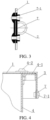
FIG. 5 is a partial enlarged view of area A inFIG. 1 . -
FIG. 6 is a partial enlarged view of area B inFIG. 1 . -
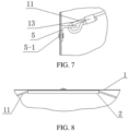
FIG. 7 is a schematic diagram of another embodiment of a fixing method of a traction wire. -
FIG. 8 is a partial enlarged view of area C inFIG. 1 . -
FIG. 9 is a schematic diagram of another embodiment of an antenna fence. -
FIG. 10 shows insertion loss comparison curves of the radome according to the present invention and an ABS radome in the prior art. - Reference numerals in the drawings: 1 radome, 1-1 reinforcing connecting layer, 2 tensioning element, 2-1 through hole, 3 pressing ring, 4 fence, 4-1 flange, 4-2 screw or blind rivet, 5 fixing component, 5-1 screw or blind rivet, 6 reflecting surface, 7 fixing sheet, 7-1 rivet, 8 back ring, 9 feed source, 10 pre-tightening screw, 10-1 projecting portion, 11 traction mechanism, 12 pre-tightening spring, 13 metal sleeve, 14 fixing screw, and 15 nut.
- The following describes the technical solutions of the present invention clearly and completely in combination with the accompanying drawings and specific embodiments. The specific contents listed in the following embodiments are not limited to the technical features necessary for the technical problems to be solved by the technical solutions described in the claims. At the same time, the embodiments listed are only part of the embodiments of the present invention, not all of them.
- A broadband flexible radome for a microwave antenna according to the present invention is an important component for protecting the microwave antenna, and is arranged on a front side of the antenna. A periphery of the radome is fixed to a
fence 4 arranged around the antenna, and is opposite to a reflectingsurface 6 of the antenna. - Unlike a conventional rigid radome made of ABS engineering plastic and the like, the
radome 1 used in the microwave antenna according to the present invention is in the form of a cloth-like flexible material. Theradome 1 of the flexible material is spread on a side opposite to the reflectingsurface 6 of the antenna, and a periphery of theradome 1 stretches and is tensioned and fixed to thefence 4 arranged around the reflecting surface of the antenna. Thefence 4 is used for limiting lateral radiation from the antenna, thereby improving the performance of the antenna. The structure and arrangement of thefence 4 are substantially the same as those in the prior art, and the same portions are not described in detail. - Since the material of the radome is flexible, the radome can be deformed into a desired concave shape by an external force such as pulling. Therefore, unlike the conventional rigid radome made of ABS engineering plastic and the like, thermoforming is not needed, and a production mold can be omitted to reduce the cost.
- The radome according to the present invention is of a flexible multilayer composite structure mainly compounded by a composite fiber textile structural layer and a high molecular polymer outer layer attached to the composite fiber textile structural layer. The high molecular polymer outer layer is mainly formed by curing a high molecular polymer coating arranged on the composite fiber textile structural layer, for example, one or more of polymer materials such as polyvinyl chloride, polypropylene and polyamide are used, and the high molecular polymer coating thereof is formed on the composite fiber textile structural layer by hot melting, coating, infiltration, etc., and then is cured to form the high molecular polymer outer layer on the composite fiber textile structural layer.
- The radome is required to have good wave transmission performance, which requires the material to have a small dielectric constant and a small tangent loss, so the specific polymer material can be selected according to the performance parameters. The mechanical properties of the material should also be considered. Although stress on the radome is mainly borne by the composite fiber textile structural layer, excellent electrical and mechanical properties can improve the performance and service life of the antenna.
- The composite fiber textile structural layer is a main structural material in the radome to increase the strength and bear the force, and is mainly made of textile fibers (e.g., polyvinyl chloride fibers, etc.) through a textile technology. Since the strength of the textile fibers such as polyvinyl chloride fibers is generally high, the manufactured radome also has high strength and tensile property, can adapt to the influence of the external environment and has good durability.
- The composite fiber textile structural layer of the present invention is different from the general textile fiber cloth. Shielding wave absorbing wires made of a shielding wave absorbing material are mixed in the textile fibers of the composite fiber textile structural layer. The shielding wave absorbing wires have the function of shielding and absorbing electromagnetic waves, and are structurally compounded with textile fibers such as polyvinyl chloride fibers by interweaving or intertwining among different fibers, or doping of the shielding wave absorbing wires in gaps of the textile fiber structure. Thus, the electrical performance of the composite fiber textile structural layer and the radome can be effectively improved, and better wave transmission performance can be achieved in comparison with the conventional textile fiber cloth. By using the radome prepared by compounding the composite fiber textile structural layer including the shielding wave absorbing wires and the high molecular polymer outer layer, the microwave antenna can achieve low insertion loss and good wave transmission performance.
- The shielding wave absorbing wires are made of a shielding wave absorbing material in the prior art, e.g., carbon black fibers, textile fibers coated with metal micro-powder, silicon carbide fibers, etc., which are not enumerated one by one herein. The fiber material of the shielding wave absorbing wires does not need to be too long, as long as it can be compounded with the textile fibers. A specific preparation method of the fiber material for the shielding wave absorbing wires and a specific spinning method of the composite fiber textile structural layer can refer to the prior art, and are not described in detail herein.
- The high molecular polymer outer layer and the composite fiber textile structural layer of the radome according to the present invention may further include some auxiliary ingredients added as needed in a specific production process, such as some ingredients for bonding, or ingredients for improving the ultraviolet protection performance, etc. When these ingredients are added according to the production needs, the auxiliary ingredients should also be regarded as a part of the high molecular polymer outer layer or the composite fiber textile structural layer.
- Since the radome materials compounded by the high molecular polymer outer layer and the conjugate fiber textile structural layer described above have high strength, excellent electrical performance and good wave transmission performance, the thickness of the radome made of these materials does not depend on the working wavelength of the antenna, and the radome has good versatility in different frequency bands. Therefore, the radome can overcome the defects of high cost, great risk of wrong mixing and the like of the conventional radomes due to many specifications, non-universality and the like. The composite flexible radome can be relatively thin, and the overall thickness can be 0.8 mm or less. Hence, the radome is very light in weight, and can reduce the overall weight of the antenna and meet a customer's requirement for lightweight.
- The flexible radome having the electrical performance improved by the shielding wave absorbing wires has relatively small loss in the frequency bands of 6G-26G, can satisfy the broadband versatility, and has the characteristics of light weight and low price.
- Since the radome of the present invention is flexible, and a desired shape can be formed by assembly, the radome does not to be manufactured by thermoforming as a rigid radome, and the production cost can be reduced. In the present invention, after the
radome 1 is mounted on thefence 4 around the reflecting surface of the antenna, theradome 1 forms a concave surface by pulling. Specifically, the following structural mode can be used. - As shown in the figure, one or
more tensioning elements 2 are arranged on a side of theradome 1 facing the reflectingsurface 6 of the antenna, and thetensioning elements 2 are fixedly connected with theradome 1 into a whole and connected with atraction mechanism 11 arranged between theradome 1 and the reflecting surfaces 6. Thetraction mechanism 11 pulls theradome 1, and is connected to an inner wall of thefence 4. Thetraction mechanism 11 applies a traction force to theradome 1 via thetensioning elements 2, and theradome 1 is deformed into a concave surface by the traction force to reduce the return loss of electromagnetic waves. - The
traction mechanism 11 may be a traction wire, a draw bar, etc., which is determined according to actual needs. In the embodiment shown inFIG. 1 , the traction mechanism is in the form of traction wires, the assembly of the traction wires is flexible, and the structure is simple and light. The traction wires are connected to thetensioning elements 2 of theradome 1, are pulled down such that theradome 1 is recessed to a desired extent, and then fixed to an inner side wall of thefence 4. - A plurality of traction wires may be symmetrically arranged between the
radome 1 and the reflectingsurface 6 as needed, and the plurality of traction wires are respectively connected to thetensioning elements 2 on theradome 1. The traction wires can be connected to thesame tensioning element 2 ordifferent tensioning elements 2 respectively. -
FIG. 1 andFIG. 8 show a preferred embodiment of the present invention, where a traction wire is used as thetraction mechanism 11, the traction wire penetrates through a through hole formed on thetensioning element 2, and two ends of the traction wire extend down obliquely to two sides. After theradome 1 is pulled and recessed to the desired extent, the two ends of the traction wire are respectively connected to the inner side wall of thefence 4. In this embodiment, since the traction wire can slide within the through hole of thetensioning element 2, when the radome is pulled down via the two ends of the traction wire, the length of the traction wire on two sides of the through hole can be automatically adjusted by sliding of the traction wire in the through hole, the length of the traction wire on two sides of thetensioning element 2 adapts to the distance from thetensioning element 2 to fixed points of the traction wire on the inner side wall of thefence 4, and the traction wire on the two sides of the through hole applies the same traction force to thetensioning element 2 and theradome 1 to ensure the balanced stress of the radome. -
FIG. 1, 2 and8 show an embodiment of atensioning element 2 suitable for a traction wire. In this embodiment, a main body of thetensioning element 2 is a connecting sheet fixed in a center of theradome 1, and the connecting sheet can be spread and fixedly connected to the radome by gluing, heat sealing, sewing, etc. The connecting sheet has a strip projecting portion, the projecting portion is provided with a through hole 2-1 penetrating in the length direction, and the through hole 2-1 extends in the diameter direction of the radome to have a relatively long axial length. After the traction wire penetrates through the through hole 2-1, its two ends are connected to two opposite fixing positions on the inner side wall of thefence 4. Since the traction wire has a long length in the through hole 2-1, the traction wire has a large range of force when pulling down thetensioning element 2 and theradome 1, and applies a more uniform force to thetensioning element 2 and theradome 1. - The
tensioning element 2 may also be in the form of a connecting pull ring, a hook or the like, as desired. - As described above, the
radome 1 is pulled down to deform into an inward concave surface, and the inclined surface formed by recessing reduces the return loss of electromagnetic waves. When theradome 1 is pulled down, a fixed part of a peripheral edge of theradome 1 on thefence 4 also needs to bear the force applied by thetraction mechanism 11. For this reason, the peripheral edge of theradome 1 needs to be firmly and stably fixed to thefence 4 around the reflectingsurface 6 of the antenna, so as not to slip under the pulling force of thetraction mechanism 11. - In order to increase the tensile strength of the peripheral edge of the
radome 1, avoid damage under the pulling action and prolong the service life, as shown inFIG. 2 , a reinforcing connectinglayer 1 connected with theradome 1 into a whole is arranged at the peripheral edge of theradome 1. The reinforcing connecting layer 1-1 may be a folded portion formed by folding the peripheral edge of the radome toward the center, or a layer of the same material as theradome 1 is laminated on the periphery of theradome 1 to form a double-layer structure. The periphery with the reinforcing connecting layer 1-1 is fixedly connected with an upper end of thefence 4 to increase the reliability of connection. -
FIG. 4 shows an embodiment of a fixing method of the peripheral edge of theradome 1. In this embodiment, the periphery of theradome 1 is fixed by apressing ring 3 with an L-shaped cross section, and the size of thepressing ring 3 is adapted to the size of an upper end of a cylinder formed by thefence 4. During fixing, thepressing ring 3 is inverted at the upper end of thefence 4, wherein one side of the L-shaped cross section of thepressing ring 3 is flush with an upper end surface of thefence 4, and the other side is attached to an outer side of thefence 4. After the peripheral edge of theradome 1 is extended and spread to the upper end of thefence 4, thepressing ring 3 is assembled in position and fixedly connected to thefence 4 by a screw or a blind rivet 4-2, and thepressing ring 3 squeezes and fixes the periphery of the radome spread to the upper end of thefence 4 in advance, so as to spread and fix the radome. Compared with a general method of pulling and fixing the edge of the radome by springs and hooks distributed on four sides of the fence, this fixing method has the advantages that the fixing structure is simpler, fewer components are required, and the cost is lower. In addition, the pressing fixation with thepressing ring 3 is simpler, reduces the labor cost during antenna installation and improves the assembly efficiency. - More preferably, as shown in the embodiment of
FIG. 4 , the overall size of theradome 1 is larger than the maximum size of the upper end of the cylinder formed by thefence 4, so that the peripheral edge of theradome 1 is spread and extends to the upper end of thefence 4 and then can be further folded down to cover the upper end of thefence 4 from the outer side. The folded peripheral edge of theradome 1 extends down in a way of being close to an outer side of thefence 4, and extends out from a gap between thepressing ring 3 and an outer side of thefence 4. A fixingsheet 7 is arranged on the extending portion of theradome 1, and the fixingsheet 7 is fixed with the periphery of theradome 1 into a whole by means of a rivet 7-1 or the like. The fixingsheet 7 is larger than the gap between thepressing ring 3 and thefence 4. After assembly, thepressing ring 3 can clamp the fixingsheet 7 and restrict the peripheral edge of theradome 1 from passing through the gap. - As shown in
FIG. 2 , in this embodiment, fixingsheets 7 are uniformly distributed on the circumferential edge of theradome 1, and are fixed with theradome 1 into a whole by means of rivets 7-1 or the like. After theradome 1 is spread, its periphery extends to the outer side of the upper end of thefence 4 and then extends down as shown inFIG. 4 , thepressing ring 3 is inverted at the upper end of thefence 4, and thepressing ring 3 clamps the fixingsheets 7 on the circumference of theradome 1 and presses the fixingsheets 7 down. On the one hand, thepressing ring 3 can press the fixing sheets during assembly to facilitate spreading of the radome; and on the other hand, thepressing ring 3 can limit thefixing sheets 7 to prevent the radome from slipping radially under the traction of thetraction mechanism 11 or an external force of wind and the like, so as to improve the firmness of fixing the periphery of the radome. - The embodiment shown in
FIG. 4 further shows a preferred embodiment of theantenna fence 4, where the upper end of thefence 4 is provided with a flange 4-1 folded down, and an upper end surface of the flange 4-1 is a flat surface for connecting and fixing theradome 1 and thepressing ring 3. The flange 4-1 increases the size of the upper end surface of thefence 4, and increases a contact surface between theradome 1 and thefence 4, that is, the area of a clamping surface, which is more advantageous for clamping and fixing the periphery of theradome 1 between thepressing ring 3 and thefence 4. - The area of the upper end surface of the
fence 4, which is increased by the flange 4-1, also facilitates the connection and fixing of thepressing ring 3. After thepressing ring 3 is assembled, thepressing ring 3, theradome 1 and the flange 4-1 of thefence 4 can be pre-tightened and connected together by screws or rivets 4-2. -
FIG. 5, 6 and7 show several specific embodiments of connection of the traction mechanism 11 (e.g., a traction wire) to the inner wall of thefence 4 respectively. - As shown in
FIG. 5 , thetraction mechanism 11 is in the form of a traction wire that is connected to the inner side wall of thefence 4 by apre-tightening screw 10. The specific structure is that an end portion of the traction wire penetrates through a hole at one end of thepre-tightening screw 10 and is fixed. One end of thepre-tightening screw 10 penetrates through a connecting hole (not shown) formed on afixing component 5 on the inner side wall of thefence 4, and thepre-tightening screw 10 is movable in the connecting hole and is pre-tightened by apre-tightening spring 12. - In the embodiment shown in
FIG. 5 , the fixingcomponent 5 is formed by angle steel which is fixed to the inner side wall of thefence 4 by a screw or a blind rivet 5-1. One of two perpendicular plate surfaces of the angle steel is attached to the inner side wall of thefence 4 and fixed by the screw or the blind rivet 5-1. The other plate surface of the angle steel is perpendicular to the inner side wall of thefence 4, and is provided with a connecting hole. The upper end of thepre-tightening screw 10 is connected to the traction wire, and the lower end penetrates through the connecting hole and is movable up and down in the connecting hole. Apre-tightening spring 12 is sleeved on a portion of thepre-tightening screw 10 penetrating through the connecting hole. A nut is screwed onto the penetrating end of thepre-tightening screw 10 penetrating through the connecting hole, and the nut forms a projecting portion 10-1 fixed to thepre-tightening screw 10. Of course, the projecting portion 10-1 can also be formed in other ways, e.g., a projecting component is welded to thepre-tightening screw 10. - As shown in
FIG. 5 , thepre-tightening spring 12 is a compression spring sandwiched between the projecting portion 10-1 of thepre-tightening screw 10 and thefixing component 5 on the inner side wall of thefence 4. Since thefixing component 5 is fixed to the inner side wall of thefence 4, elastic force of thepre-tightening spring 12 is applied downward to thepre-tightening screw 10 via the projecting portion 10-1, and thus a downward elastic pre-tightening force is applied to the traction wire fixed to the upper end of thepre-tightening screw 10 and the radome pulled by the traction wire. This embodiment shows an elastic pre-tightening connection form, where the elastic pre-tightening force applied to the traction wire by thepre-tightening spring 12 and thepre-tightening screw 10 can always keep theradome 1 tightened and spread without being relaxed as the service time goes. Therefore, the increase in vibration amplitude under the action of wind power due to the relaxation of theradome 1 can be prevented, fatigue loss caused by repeated deformation of the radome is then relieved, and the service life of the radome is prolonged. - Since the
traction mechanism 11 in the form of a traction wire used in the above embodiment of the present invention penetrates through the through hole of thetensioning element 2 and is movable in the through hole, the traction wire on two sides of the through hole is equally stressed, and the entire traction wire can be pre-tightened by applying the elastic pre-tightening force on one side. The connection of elastic pre-tightening can be only for one end of the traction wire as shown inFIG. 1 , while the other end of the traction wire is in other form of fixed connection. The pre-tightening connection of thepre-tightening screw 10 and thepre-tightening spring 12 can also be used at two ends of the traction wire. - The embodiment shown in
FIG. 6 indicates a fixed connection form of the traction wire. In this embodiment, afixing component 5 is also arranged on an inner side wall of thefence 4, and thefixing component 5 can be formed by angle steel fixed to the inner side wall of thefence 4 by a screw or a blind rivet 5-1 according to the embodiment shown inFIG. 5 . A connecting hole is also formed on a plate surface of the angle steel perpendicular to the inner side wall of thefence 4. The connecting hole may be a threaded hole or an unthreaded hole. The traction wire is connected to a fixingscrew 14. As shown inFIG. 6 , an end portion of the traction wire passes through a hole at the upper end of the fixingscrew 14 and is fixed. A lower end of the fixingscrew 14 passes through a connecting hole on thefixing component 5 and is directly fixed by a nut. Compared with the embodiment shown inFIG. 5 , this embodiment does not use a pre-tightening spring, but directly uses a nut for fixing. Therefore, the connection is a rigid fixed connection, and does not function as the elastic pre-tightening connection. - The fixed connection described in this embodiment can be used together with the elastic connection of the pre-tightening screw shown in
FIG. 5 . As shown inFIG. 1 , in the case where the elastic pre-tightening connection of thepre-tightening screw 10 and thepre-tightening spring 12 is used at one end of the traction wire, the fixed connection shown in this embodiment is used at the other end. - The embodiment shown in
FIG. 7 gives another form of fixed connection of the traction wire. In this embodiment, afixing component 5 also needs to be arranged on an inner side wall of thefence 4, the fixingcomponent 5 can be in the form of the angle steel shown in the above embodiment ofFIG. 5 or FIG. 6 , and a plate surface of the angle steel perpendicular to the inner side wall of thefence 4 is provided with a connecting hole. The connecting hole is a threading hole, and can be smaller than the connecting hole in the embodiment shown inFIG. 5 or FIG. 6 . An end portion of the traction wire penetrates through the connecting hole on thefixing component 5, and the portion of the traction wire penetrating out of the connecting hole (i.e., the penetrating end of the traction wire) is folded backward. After the folded penetrating end is clamped by a wire puller and the traction wire is pre-tightened, ametal sleeve 13 is sleeved on the backward-folded penetrating end of the traction wire and the traction wire close to the penetrating end, and then an external force is applied to plastically deform and press themetal sleeve 13, so that the backward-folded end portion of the traction wire is fixedly connected to the portion of the traction wire not penetrating through the connecting hole by themetal sleeve 13 to achieve the function of fixing the traction wire. - The connection described in this embodiment can be used for the connection of two ends of the traction wire, or only for connecting one end of the traction wire, and the other end adopts the connection form shown in
FIG. 5 or FIG. 6 . -
FIG. 9 shows another embodiment of the microwave antenna, which is different from the form of the straightcylindrical fence 4 shown inFIG. 1 . In this embodiment, thefence 4 is inclined and the heights of four sides can be different, so that theradome 1 is arranged obliquely. The fixed connection of theradome 1, the tightening of the traction wire and the connection of the end portion of the traction wire as shown in the above embodiments are also applicable to the inclined fence of this embodiment. Moreover, the radome can also be well and stably spread and fixed by the above ways. -
FIG. 10 shows a changing curve of the insertion loss of the microwave antenna using the radome of the present invention along with the frequency. The flexible radome has a low insertion loss within the frequency range of 6G-26G, not more than 0.3 dB, and the insertion loss is little affected by the frequency, which can meet the versatility of the broadband microwave antenna. - The radome of the present invention is compounded by a high molecular polymer outer layer and a composite fiber textile structural layer, shielding wave absorbing wires are compounded in the composite fiber textile structural layer, and this composite structure can effectively improve the electrical performance of the radome, reduce the antenna insertion loss and improve the wave transmission performance. The antenna insertion loss of the radome according to the present invention is maintained at a relatively stable low value within a wide frequency range. Compared with the conventional radome, the antenna insertion loss is not greatly increased due to the variation of the frequency band, so the radome is versatile in a relatively wide frequency range.
- The radome of this structure has good wave transmission performance, and the thickness selection of the radome does not depend on the working wavelength of the antenna. By using the radome of a uniform thickness, low antenna insertion loss can be achieved in multiple frequency bands, the use of a multi-band microwave antenna can be met, the versatility of the radome is realized within a wide frequency range, and the defect of difference of the conventional radome made of ABS and the like in different frequency bands is overcome.
- The radome is made of a flexible material that does not require excessive thickness to have high strength compared with a rigid material, so the radome is relatively thin and light in weight. Compared with a general flexible radome, a high molecular polymer is used as the radome outer layer, and shielding wave absorbing wires are compounded in the composite fiber textile structural layer, so that the radome of the present invention has higher electrical performance and wave transmission performance than the general flexible radome cloth.
- The flexible radome of the present invention is recessed to form a concave surface by means of the traction force of the traction mechanism to reduce the return loss of electromagnetic waves on the one hand, and the radome can be tightened by the traction force of the traction mechanism on the other hand. The traction mechanism also plays a fixing role to limit the vibration of the radome under wind power, thereby relieving the fatigue loss caused by repeated deformation of the radome, and prolonging the service life of the radome.
- The radome has high versatility and good and stable electrical performance in a full frequency range, greatly reduces the weight of the antenna and lowers the production cost of the antenna.
- The above descriptions of the specific embodiments are only for helping understanding the technical concept of the present invention and the core idea thereof. Although the technical solution is described and illustrated using specific preferred embodiments, the present invention should not be limited thereto. Various changes in form and detail may be made by those skilled in the art without departing from the technical thought of the present invention which is defined by the appended claims.
- These easily conceivable changes or substitutions shall fall within the protection scope of the present invention which is defined by the appended claims.
Claims (9)
- A broadband flexible radome for a microwave antenna,wherein the microwave antenna comprises a fence (4) arranged around the antenna and a reflecting surface (6),wherein the radome is configured to be opposite to the reflecting surface (6) andwherein the radome comprises a periphery of which is configured to be fixed to the fence (4), wherein the radome (1) is compounded by a high molecular polymer outer layer and a composite fiber textile structural layer mixed with a shielding wave absorbing wire,wherein the radome comprises a tensioning element (2) for connecting a traction mechanism (11) of the radome, the tensioning element (2) being arranged on a side of the radome (1) configured to face the reflecting surface (6) of the antenna,wherein the traction mechanism (11) is configured to be connected to an inner wall of the fence (4), such that the traction mechanism (11) deforms the radome (1) into a concave surface by means of a traction force acting on the radome (1).
- The broadband flexible radome for a microwave antenna according to claim 1, further comprising a reinforcing connecting layer (1-1) wherein the reinforcing connecting layer (1-1) connected with the radome into a whole is arranged on the periphery of the radome (1).
- The broadband flexible radome for a microwave antenna according to claim 1,wherein the radome comprises a pressing ring (3) with an L-shaped cross section wherein the pressing ring (3) is configured to be inverted at an upper end of the fence (4),and wherein the periphery of the radome (1) is configured to be squeezed and fixed to the fence (4) by the pressing ring.
- The broadband flexible radome for a microwave antenna according to claim 3, wherein the periphery of the radome (1) is configured to be folded to cover the upper end of the fence (4),wherein a peripheral edge of the radome is configured to extend out from a gap between the pressing ring (3) and the fence (4),and wherein the radome further comprises a fixing sheet (7) for limiting the peripheral edge from passing through the gap, wherein the fixing sheet is fixed on the peripheral edge.
- The broadband flexible radome for a microwave antenna according to claim 3 or 4, wherein the upper end of the fence is provided with a flange (4-1) folded down, and the pressing ring (3) is configured to be fixed on the flange (4-1) by a screw or a blind rivet.
- The broadband flexible radome for a microwave antenna according to claim 1, wherein the traction mechanism (11) is a traction wire penetrating through a through hole formed on the tensioning element (2), and two ends of the traction wire are respectively configured to be connected to the inner side wall of the fence (4).
- The broadband flexible radome for a microwave antenna according to claim 6, wherein the tensioning element (2) is a connecting sheet fixed in a center of the radome (1), and the connecting sheet is provided with a through hole (2-1) extending in a diameter direction of the radome.
- The broadband flexible radome for a microwave antenna according to claim 6 or 7,wherein an end portion of the traction wire is connected to a pre-tightening screw (10), of the radome,wherein one end of the pre-tightening screw (10) is configured to penetrate through a connecting hole on a fixing component (5) of the fence (4), the fixing component (5) being on the inner side wall of the fence (4), and wherein a pre-tightening spring (12) of the radome is sleeved between a projecting portion (10-1) of the one end of the pre-tightening screw and the fixing component (5).
- The broadband flexible radome for a microwave antenna according to claim 6 or 7,
wherein the end portion of the traction wire is configured to penetrate through a connecting hole of a fixing component (5) of the fence (4), the fixing component (5) being on the inner side wall of the fence (4), and the end portion of the traction wire is configured to be folded backward, and to be fixedly connected with a portion of the traction wire not penetrating through the connecting hole by a metal sleeve (13) of the radome.
Applications Claiming Priority (2)
| Application Number | Priority Date | Filing Date | Title |
|---|---|---|---|
| CN201810149166.8A CN108461916B (en) | 2018-02-13 | 2018-02-13 | Broadband flexible antenna housing of microwave antenna |
| PCT/CN2018/081240 WO2019157770A1 (en) | 2018-02-13 | 2018-03-30 | Wide-band flexible radome for microwave antenna |
Publications (4)
| Publication Number | Publication Date |
|---|---|
| EP3754785A1 EP3754785A1 (en) | 2020-12-23 |
| EP3754785A4 EP3754785A4 (en) | 2021-10-27 |
| EP3754785C0 EP3754785C0 (en) | 2023-07-26 |
| EP3754785B1 true EP3754785B1 (en) | 2023-07-26 |
Family
ID=63217025
Family Applications (1)
| Application Number | Title | Priority Date | Filing Date |
|---|---|---|---|
| EP18906409.0A Active EP3754785B1 (en) | 2018-02-13 | 2018-03-30 | Wide-band flexible radome for microwave antenna |
Country Status (3)
| Country | Link |
|---|---|
| EP (1) | EP3754785B1 (en) |
| CN (1) | CN108461916B (en) |
| WO (1) | WO2019157770A1 (en) |
Families Citing this family (10)
| Publication number | Priority date | Publication date | Assignee | Title |
|---|---|---|---|---|
| CN109103594B (en) * | 2018-08-30 | 2024-06-04 | 广东通宇通讯股份有限公司 | Antenna housing for microwave antenna |
| CN108963417A (en) * | 2018-08-30 | 2018-12-07 | 广东通宇通讯股份有限公司 | A kind of microwave antenna being easily achieved different frequency range switching |
| CN109188561B (en) * | 2018-09-19 | 2023-10-20 | 北京洛达世安电子设备有限公司 | Microwave testing tool and testing method thereof |
| US11588232B2 (en) | 2018-10-12 | 2023-02-21 | Commscope Technologies Llc | Flexible radome structures |
| CN109400194B (en) * | 2018-10-30 | 2021-07-09 | 山东工业陶瓷研究设计院有限公司 | Fiber-reinforced ceramic matrix composite material radome for W-band and preparation method thereof |
| CN111987450B (en) * | 2020-07-31 | 2021-05-28 | 中国航空工业集团公司济南特种结构研究所 | Protective function antenna structure |
| CN113964516B (en) * | 2021-09-27 | 2022-12-09 | 浙江大学 | Two-dimensional beam scanning antenna based on adjustable antenna housing |
| CN115158980B (en) * | 2022-07-04 | 2025-10-31 | 中山市诚力通通信科技有限公司 | Antenna housing tractor |
| CN115548669A (en) * | 2022-09-16 | 2022-12-30 | 刘永梅 | Self-adjusting cover of microwave antenna for mobile base station |
| CN116315573B (en) * | 2023-03-10 | 2026-04-24 | 中国人民解放军空军工程大学 | An offset microwave antenna |
Citations (1)
| Publication number | Priority date | Publication date | Assignee | Title |
|---|---|---|---|---|
| EP3207592B1 (en) * | 2014-10-14 | 2021-04-14 | Ubiquiti Inc. | Signal isolation shrouds and reflectors for antenna |
Family Cites Families (12)
| Publication number | Priority date | Publication date | Assignee | Title |
|---|---|---|---|---|
| US3388401A (en) * | 1965-06-30 | 1968-06-11 | Andrew Antenna Company Ltd | Parabolic antenna with low-loss flexible radome |
| US7560400B2 (en) * | 2003-07-16 | 2009-07-14 | Raytheon Company | Radome with polyester-polyarylate fibers and a method of making same |
| FR2894391B1 (en) * | 2005-12-06 | 2008-01-04 | Alcatel Sa | RADIO COMMUNICATION ANTENNA WITH RADOME AND METHOD FOR ASSEMBLING SUCH A RADIO RADIO ANTENNA WITH RADOME |
| CN101958461B (en) * | 2010-09-07 | 2013-11-20 | 京信通信系统(中国)有限公司 | Microwave antenna and outer cover thereof |
| JP5892352B2 (en) * | 2011-03-22 | 2016-03-23 | ディーエスエム アイピー アセッツ ビー.ブイ. | Inflatable radome |
| SE536447C2 (en) * | 2012-03-27 | 2013-11-05 | Induflex AB | Clamping device for stretching a radar cloth |
| US9583822B2 (en) * | 2013-10-30 | 2017-02-28 | Commscope Technologies Llc | Broad band radome for microwave antenna |
| WO2017103008A1 (en) * | 2015-12-18 | 2017-06-22 | Dsm Ip Assets B.V. | Radome wall with multilayer polymer sheet |
| EP3220548B1 (en) * | 2016-03-18 | 2018-12-12 | Huawei Technologies Co., Ltd. | Antenna housing with tension element |
| CN205790373U (en) * | 2016-06-27 | 2016-12-07 | 武汉凡谷电子技术股份有限公司 | A kind of microwave antenna |
| CN206480762U (en) * | 2016-12-27 | 2017-09-08 | 广东通宇通讯股份有限公司 | Antenna system and its radome |
| CN207925674U (en) * | 2018-02-13 | 2018-09-28 | 广东通宇通讯股份有限公司 | Broadband flexible radome for microwave antenna |
-
2018
- 2018-02-13 CN CN201810149166.8A patent/CN108461916B/en active Active
- 2018-03-30 EP EP18906409.0A patent/EP3754785B1/en active Active
- 2018-03-30 WO PCT/CN2018/081240 patent/WO2019157770A1/en not_active Ceased
Patent Citations (1)
| Publication number | Priority date | Publication date | Assignee | Title |
|---|---|---|---|---|
| EP3207592B1 (en) * | 2014-10-14 | 2021-04-14 | Ubiquiti Inc. | Signal isolation shrouds and reflectors for antenna |
Also Published As
| Publication number | Publication date |
|---|---|
| EP3754785C0 (en) | 2023-07-26 |
| WO2019157770A1 (en) | 2019-08-22 |
| CN108461916A (en) | 2018-08-28 |
| CN108461916B (en) | 2020-04-17 |
| EP3754785A1 (en) | 2020-12-23 |
| EP3754785A4 (en) | 2021-10-27 |
Similar Documents
| Publication | Publication Date | Title |
|---|---|---|
| EP3754785A1 (en) | Wide-band flexible radome for microwave antenna | |
| CA2873019C (en) | Antenna device and method for attaching the same | |
| US9422914B2 (en) | Radar absorbing material compatible with lightning protection systems | |
| US20070229379A1 (en) | Digital UHF/VHF antenna | |
| CN207925674U (en) | Broadband flexible radome for microwave antenna | |
| WO2011148236A1 (en) | Segmented antenna reflector with shield | |
| US11588232B2 (en) | Flexible radome structures | |
| CN110212297A (en) | Airborne lightning protection antenna cover | |
| EP1644185B1 (en) | Radome with polyester-polyarylate fibers and a method of making same | |
| CN108539410A (en) | A kind of stacking micro-strip UHF antenna | |
| US4507341A (en) | Carbon fibre structures | |
| EP3832794B1 (en) | Antenna system | |
| JP5263957B2 (en) | Radome and manufacturing method thereof | |
| CA2532274A1 (en) | Rigid radome with polyester-polyarylate fibers and a method of making same | |
| CN223105827U (en) | A fixing strap capable of adapting to the expansion of a hydrogen storage tank | |
| US20170358855A1 (en) | Antenna radome with absorbers | |
| CN207925673U (en) | a kind of microwave antenna cover cloth fixing structure | |
| CN212462024U (en) | A microwave antenna broadband flexible radome | |
| US20150249281A1 (en) | Joining device for fastening a radome onto an antenna reflector | |
| CA2604405A1 (en) | Digital uhf/vhf antenna | |
| CN109103594A (en) | A kind of antenna house for microwave antenna | |
| CN115313041A (en) | Connecting structure of frame and membrane material of net frame type radome unit structure | |
| CN208674368U (en) | A kind of antenna house for microwave antenna | |
| CN215645033U (en) | Three-frequency-band common antenna | |
| CN222940203U (en) | A microwave antenna protection cover structure |
Legal Events
| Date | Code | Title | Description |
|---|---|---|---|
| STAA | Information on the status of an ep patent application or granted ep patent |
Free format text: STATUS: THE INTERNATIONAL PUBLICATION HAS BEEN MADE |
|
| PUAI | Public reference made under article 153(3) epc to a published international application that has entered the european phase |
Free format text: ORIGINAL CODE: 0009012 |
|
| STAA | Information on the status of an ep patent application or granted ep patent |
Free format text: STATUS: REQUEST FOR EXAMINATION WAS MADE |
|
| 17P | Request for examination filed |
Effective date: 20191218 |
|
| AK | Designated contracting states |
Kind code of ref document: A1 Designated state(s): AL AT BE BG CH CY CZ DE DK EE ES FI FR GB GR HR HU IE IS IT LI LT LU LV MC MK MT NL NO PL PT RO RS SE SI SK SM TR |
|
| AX | Request for extension of the european patent |
Extension state: BA ME |
|
| DAV | Request for validation of the european patent (deleted) | ||
| DAX | Request for extension of the european patent (deleted) | ||
| A4 | Supplementary search report drawn up and despatched |
Effective date: 20210928 |
|
| RIC1 | Information provided on ipc code assigned before grant |
Ipc: H01Q 1/42 20060101AFI20210922BHEP |
|
| GRAP | Despatch of communication of intention to grant a patent |
Free format text: ORIGINAL CODE: EPIDOSNIGR1 |
|
| STAA | Information on the status of an ep patent application or granted ep patent |
Free format text: STATUS: GRANT OF PATENT IS INTENDED |
|
| RIC1 | Information provided on ipc code assigned before grant |
Ipc: H01Q 19/19 20060101ALN20230127BHEP Ipc: H01Q 1/42 20060101AFI20230127BHEP |
|
| RIC1 | Information provided on ipc code assigned before grant |
Ipc: H01Q 19/19 20060101ALN20230207BHEP Ipc: H01Q 1/42 20060101AFI20230207BHEP |
|
| INTG | Intention to grant announced |
Effective date: 20230222 |
|
| GRAS | Grant fee paid |
Free format text: ORIGINAL CODE: EPIDOSNIGR3 |
|
| GRAA | (expected) grant |
Free format text: ORIGINAL CODE: 0009210 |
|
| STAA | Information on the status of an ep patent application or granted ep patent |
Free format text: STATUS: THE PATENT HAS BEEN GRANTED |
|
| AK | Designated contracting states |
Kind code of ref document: B1 Designated state(s): AL AT BE BG CH CY CZ DE DK EE ES FI FR GB GR HR HU IE IS IT LI LT LU LV MC MK MT NL NO PL PT RO RS SE SI SK SM TR |
|
| REG | Reference to a national code |
Ref country code: CH Ref legal event code: EP |
|
| REG | Reference to a national code |
Ref country code: DE Ref legal event code: R096 Ref document number: 602018054315 Country of ref document: DE |
|
| REG | Reference to a national code |
Ref country code: IE Ref legal event code: FG4D |
|
| U01 | Request for unitary effect filed |
Effective date: 20230811 |
|
| U07 | Unitary effect registered |
Designated state(s): AT BE BG DE DK EE FI FR IT LT LU LV MT NL PT SE SI Effective date: 20230912 |
|
| REG | Reference to a national code |
Ref country code: LT Ref legal event code: MG9D |
|
| PG25 | Lapsed in a contracting state [announced via postgrant information from national office to epo] |
Ref country code: GR Free format text: LAPSE BECAUSE OF FAILURE TO SUBMIT A TRANSLATION OF THE DESCRIPTION OR TO PAY THE FEE WITHIN THE PRESCRIBED TIME-LIMIT Effective date: 20231027 |
|
| PG25 | Lapsed in a contracting state [announced via postgrant information from national office to epo] |
Ref country code: IS Free format text: LAPSE BECAUSE OF FAILURE TO SUBMIT A TRANSLATION OF THE DESCRIPTION OR TO PAY THE FEE WITHIN THE PRESCRIBED TIME-LIMIT Effective date: 20231126 |
|
| PG25 | Lapsed in a contracting state [announced via postgrant information from national office to epo] |
Ref country code: RS Free format text: LAPSE BECAUSE OF FAILURE TO SUBMIT A TRANSLATION OF THE DESCRIPTION OR TO PAY THE FEE WITHIN THE PRESCRIBED TIME-LIMIT Effective date: 20230726 Ref country code: NO Free format text: LAPSE BECAUSE OF FAILURE TO SUBMIT A TRANSLATION OF THE DESCRIPTION OR TO PAY THE FEE WITHIN THE PRESCRIBED TIME-LIMIT Effective date: 20231026 Ref country code: IS Free format text: LAPSE BECAUSE OF FAILURE TO SUBMIT A TRANSLATION OF THE DESCRIPTION OR TO PAY THE FEE WITHIN THE PRESCRIBED TIME-LIMIT Effective date: 20231126 Ref country code: HR Free format text: LAPSE BECAUSE OF FAILURE TO SUBMIT A TRANSLATION OF THE DESCRIPTION OR TO PAY THE FEE WITHIN THE PRESCRIBED TIME-LIMIT Effective date: 20230726 Ref country code: GR Free format text: LAPSE BECAUSE OF FAILURE TO SUBMIT A TRANSLATION OF THE DESCRIPTION OR TO PAY THE FEE WITHIN THE PRESCRIBED TIME-LIMIT Effective date: 20231027 |
|
| PG25 | Lapsed in a contracting state [announced via postgrant information from national office to epo] |
Ref country code: PL Free format text: LAPSE BECAUSE OF FAILURE TO SUBMIT A TRANSLATION OF THE DESCRIPTION OR TO PAY THE FEE WITHIN THE PRESCRIBED TIME-LIMIT Effective date: 20230726 |
|
| PG25 | Lapsed in a contracting state [announced via postgrant information from national office to epo] |
Ref country code: ES Free format text: LAPSE BECAUSE OF FAILURE TO SUBMIT A TRANSLATION OF THE DESCRIPTION OR TO PAY THE FEE WITHIN THE PRESCRIBED TIME-LIMIT Effective date: 20230726 |
|
| REG | Reference to a national code |
Ref country code: DE Ref legal event code: R097 Ref document number: 602018054315 Country of ref document: DE |
|
| PG25 | Lapsed in a contracting state [announced via postgrant information from national office to epo] |
Ref country code: SM Free format text: LAPSE BECAUSE OF FAILURE TO SUBMIT A TRANSLATION OF THE DESCRIPTION OR TO PAY THE FEE WITHIN THE PRESCRIBED TIME-LIMIT Effective date: 20230726 Ref country code: RO Free format text: LAPSE BECAUSE OF FAILURE TO SUBMIT A TRANSLATION OF THE DESCRIPTION OR TO PAY THE FEE WITHIN THE PRESCRIBED TIME-LIMIT Effective date: 20230726 Ref country code: ES Free format text: LAPSE BECAUSE OF FAILURE TO SUBMIT A TRANSLATION OF THE DESCRIPTION OR TO PAY THE FEE WITHIN THE PRESCRIBED TIME-LIMIT Effective date: 20230726 Ref country code: CZ Free format text: LAPSE BECAUSE OF FAILURE TO SUBMIT A TRANSLATION OF THE DESCRIPTION OR TO PAY THE FEE WITHIN THE PRESCRIBED TIME-LIMIT Effective date: 20230726 Ref country code: SK Free format text: LAPSE BECAUSE OF FAILURE TO SUBMIT A TRANSLATION OF THE DESCRIPTION OR TO PAY THE FEE WITHIN THE PRESCRIBED TIME-LIMIT Effective date: 20230726 |
|
| PLBE | No opposition filed within time limit |
Free format text: ORIGINAL CODE: 0009261 |
|
| STAA | Information on the status of an ep patent application or granted ep patent |
Free format text: STATUS: NO OPPOSITION FILED WITHIN TIME LIMIT |
|
| 26N | No opposition filed |
Effective date: 20240429 |
|
| U21 | Renewal fee for the european patent with unitary effect paid with additional fee |
Year of fee payment: 7 Effective date: 20240527 |
|
| REG | Reference to a national code |
Ref country code: CH Ref legal event code: PL |
|
| PG25 | Lapsed in a contracting state [announced via postgrant information from national office to epo] |
Ref country code: MC Free format text: LAPSE BECAUSE OF FAILURE TO SUBMIT A TRANSLATION OF THE DESCRIPTION OR TO PAY THE FEE WITHIN THE PRESCRIBED TIME-LIMIT Effective date: 20230726 |
|
| GBPC | Gb: european patent ceased through non-payment of renewal fee |
Effective date: 20240330 |
|
| PG25 | Lapsed in a contracting state [announced via postgrant information from national office to epo] |
Ref country code: MC Free format text: LAPSE BECAUSE OF FAILURE TO SUBMIT A TRANSLATION OF THE DESCRIPTION OR TO PAY THE FEE WITHIN THE PRESCRIBED TIME-LIMIT Effective date: 20230726 |
|
| PG25 | Lapsed in a contracting state [announced via postgrant information from national office to epo] |
Ref country code: GB Free format text: LAPSE BECAUSE OF NON-PAYMENT OF DUE FEES Effective date: 20240330 |
|
| PG25 | Lapsed in a contracting state [announced via postgrant information from national office to epo] |
Ref country code: IE Free format text: LAPSE BECAUSE OF NON-PAYMENT OF DUE FEES Effective date: 20240330 |
|
| PG25 | Lapsed in a contracting state [announced via postgrant information from national office to epo] |
Ref country code: IE Free format text: LAPSE BECAUSE OF NON-PAYMENT OF DUE FEES Effective date: 20240330 Ref country code: GB Free format text: LAPSE BECAUSE OF NON-PAYMENT OF DUE FEES Effective date: 20240330 Ref country code: CH Free format text: LAPSE BECAUSE OF NON-PAYMENT OF DUE FEES Effective date: 20240331 |
|
| U20 | Renewal fee for the european patent with unitary effect paid |
Year of fee payment: 8 Effective date: 20250225 |
|
| PG25 | Lapsed in a contracting state [announced via postgrant information from national office to epo] |
Ref country code: CY Free format text: LAPSE BECAUSE OF FAILURE TO SUBMIT A TRANSLATION OF THE DESCRIPTION OR TO PAY THE FEE WITHIN THE PRESCRIBED TIME-LIMIT; INVALID AB INITIO Effective date: 20180330 |
|
| PG25 | Lapsed in a contracting state [announced via postgrant information from national office to epo] |
Ref country code: HU Free format text: LAPSE BECAUSE OF FAILURE TO SUBMIT A TRANSLATION OF THE DESCRIPTION OR TO PAY THE FEE WITHIN THE PRESCRIBED TIME-LIMIT; INVALID AB INITIO Effective date: 20180330 |
|
| PG25 | Lapsed in a contracting state [announced via postgrant information from national office to epo] |
Ref country code: TR Free format text: LAPSE BECAUSE OF FAILURE TO SUBMIT A TRANSLATION OF THE DESCRIPTION OR TO PAY THE FEE WITHIN THE PRESCRIBED TIME-LIMIT Effective date: 20230726 |
|
| U20 | Renewal fee for the european patent with unitary effect paid |
Year of fee payment: 9 Effective date: 20260226 |