EP3754746A1 - Bus bar module - Google Patents
Bus bar module Download PDFInfo
- Publication number
- EP3754746A1 EP3754746A1 EP20180002.6A EP20180002A EP3754746A1 EP 3754746 A1 EP3754746 A1 EP 3754746A1 EP 20180002 A EP20180002 A EP 20180002A EP 3754746 A1 EP3754746 A1 EP 3754746A1
- Authority
- EP
- European Patent Office
- Prior art keywords
- bus bar
- projection
- support portion
- electrode
- electrical connection
- Prior art date
- Legal status (The legal status is an assumption and is not a legal conclusion. Google has not performed a legal analysis and makes no representation as to the accuracy of the status listed.)
- Granted
Links
- 239000002184 metal Substances 0.000 claims description 5
- 238000006073 displacement reaction Methods 0.000 description 18
- 230000005489 elastic deformation Effects 0.000 description 4
- 230000002093 peripheral effect Effects 0.000 description 3
- 210000000078 claw Anatomy 0.000 description 2
- 238000012544 monitoring process Methods 0.000 description 2
- 238000005452 bending Methods 0.000 description 1
- 238000001514 detection method Methods 0.000 description 1
- 239000000463 material Substances 0.000 description 1
- 238000004080 punching Methods 0.000 description 1
- 229920003002 synthetic resin Polymers 0.000 description 1
- 239000000057 synthetic resin Substances 0.000 description 1
- 238000003466 welding Methods 0.000 description 1
Images


Classifications
-
- H—ELECTRICITY
- H01—ELECTRIC ELEMENTS
- H01M—PROCESSES OR MEANS, e.g. BATTERIES, FOR THE DIRECT CONVERSION OF CHEMICAL ENERGY INTO ELECTRICAL ENERGY
- H01M10/00—Secondary cells; Manufacture thereof
- H01M10/42—Methods or arrangements for servicing or maintenance of secondary cells or secondary half-cells
- H01M10/425—Structural combination with electronic components, e.g. electronic circuits integrated to the outside of the casing
-
- H—ELECTRICITY
- H01—ELECTRIC ELEMENTS
- H01M—PROCESSES OR MEANS, e.g. BATTERIES, FOR THE DIRECT CONVERSION OF CHEMICAL ENERGY INTO ELECTRICAL ENERGY
- H01M10/00—Secondary cells; Manufacture thereof
- H01M10/42—Methods or arrangements for servicing or maintenance of secondary cells or secondary half-cells
- H01M10/48—Accumulators combined with arrangements for measuring, testing or indicating the condition of cells, e.g. the level or density of the electrolyte
- H01M10/482—Accumulators combined with arrangements for measuring, testing or indicating the condition of cells, e.g. the level or density of the electrolyte for several batteries or cells simultaneously or sequentially
-
- H—ELECTRICITY
- H01—ELECTRIC ELEMENTS
- H01M—PROCESSES OR MEANS, e.g. BATTERIES, FOR THE DIRECT CONVERSION OF CHEMICAL ENERGY INTO ELECTRICAL ENERGY
- H01M50/00—Constructional details or processes of manufacture of the non-active parts of electrochemical cells other than fuel cells, e.g. hybrid cells
- H01M50/50—Current conducting connections for cells or batteries
- H01M50/502—Interconnectors for connecting terminals of adjacent batteries; Interconnectors for connecting cells outside a battery casing
- H01M50/507—Interconnectors for connecting terminals of adjacent batteries; Interconnectors for connecting cells outside a battery casing comprising an arrangement of two or more busbars within a container structure, e.g. busbar modules
-
- H—ELECTRICITY
- H01—ELECTRIC ELEMENTS
- H01M—PROCESSES OR MEANS, e.g. BATTERIES, FOR THE DIRECT CONVERSION OF CHEMICAL ENERGY INTO ELECTRICAL ENERGY
- H01M50/00—Constructional details or processes of manufacture of the non-active parts of electrochemical cells other than fuel cells, e.g. hybrid cells
- H01M50/50—Current conducting connections for cells or batteries
- H01M50/502—Interconnectors for connecting terminals of adjacent batteries; Interconnectors for connecting cells outside a battery casing
- H01M50/514—Methods for interconnecting adjacent batteries or cells
- H01M50/517—Methods for interconnecting adjacent batteries or cells by fixing means, e.g. screws, rivets or bolts
-
- H—ELECTRICITY
- H01—ELECTRIC ELEMENTS
- H01M—PROCESSES OR MEANS, e.g. BATTERIES, FOR THE DIRECT CONVERSION OF CHEMICAL ENERGY INTO ELECTRICAL ENERGY
- H01M50/00—Constructional details or processes of manufacture of the non-active parts of electrochemical cells other than fuel cells, e.g. hybrid cells
- H01M50/50—Current conducting connections for cells or batteries
- H01M50/502—Interconnectors for connecting terminals of adjacent batteries; Interconnectors for connecting cells outside a battery casing
- H01M50/521—Interconnectors for connecting terminals of adjacent batteries; Interconnectors for connecting cells outside a battery casing characterised by the material
- H01M50/522—Inorganic material
-
- H—ELECTRICITY
- H01—ELECTRIC ELEMENTS
- H01M—PROCESSES OR MEANS, e.g. BATTERIES, FOR THE DIRECT CONVERSION OF CHEMICAL ENERGY INTO ELECTRICAL ENERGY
- H01M50/00—Constructional details or processes of manufacture of the non-active parts of electrochemical cells other than fuel cells, e.g. hybrid cells
- H01M50/50—Current conducting connections for cells or batteries
- H01M50/502—Interconnectors for connecting terminals of adjacent batteries; Interconnectors for connecting cells outside a battery casing
- H01M50/521—Interconnectors for connecting terminals of adjacent batteries; Interconnectors for connecting cells outside a battery casing characterised by the material
- H01M50/524—Organic material
-
- H—ELECTRICITY
- H01—ELECTRIC ELEMENTS
- H01M—PROCESSES OR MEANS, e.g. BATTERIES, FOR THE DIRECT CONVERSION OF CHEMICAL ENERGY INTO ELECTRICAL ENERGY
- H01M10/00—Secondary cells; Manufacture thereof
- H01M10/60—Heating or cooling; Temperature control
- H01M10/63—Control systems
-
- H—ELECTRICITY
- H01—ELECTRIC ELEMENTS
- H01M—PROCESSES OR MEANS, e.g. BATTERIES, FOR THE DIRECT CONVERSION OF CHEMICAL ENERGY INTO ELECTRICAL ENERGY
- H01M2220/00—Batteries for particular applications
- H01M2220/20—Batteries in motive systems, e.g. vehicle, ship, plane
-
- H—ELECTRICITY
- H01—ELECTRIC ELEMENTS
- H01M—PROCESSES OR MEANS, e.g. BATTERIES, FOR THE DIRECT CONVERSION OF CHEMICAL ENERGY INTO ELECTRICAL ENERGY
- H01M50/00—Constructional details or processes of manufacture of the non-active parts of electrochemical cells other than fuel cells, e.g. hybrid cells
- H01M50/20—Mountings; Secondary casings or frames; Racks, modules or packs; Suspension devices; Shock absorbers; Transport or carrying devices; Holders
- H01M50/204—Racks, modules or packs for multiple batteries or multiple cells
- H01M50/207—Racks, modules or packs for multiple batteries or multiple cells characterised by their shape
- H01M50/209—Racks, modules or packs for multiple batteries or multiple cells characterised by their shape adapted for prismatic or rectangular cells
-
- Y—GENERAL TAGGING OF NEW TECHNOLOGICAL DEVELOPMENTS; GENERAL TAGGING OF CROSS-SECTIONAL TECHNOLOGIES SPANNING OVER SEVERAL SECTIONS OF THE IPC; TECHNICAL SUBJECTS COVERED BY FORMER USPC CROSS-REFERENCE ART COLLECTIONS [XRACs] AND DIGESTS
- Y02—TECHNOLOGIES OR APPLICATIONS FOR MITIGATION OR ADAPTATION AGAINST CLIMATE CHANGE
- Y02E—REDUCTION OF GREENHOUSE GAS [GHG] EMISSIONS, RELATED TO ENERGY GENERATION, TRANSMISSION OR DISTRIBUTION
- Y02E60/00—Enabling technologies; Technologies with a potential or indirect contribution to GHG emissions mitigation
- Y02E60/10—Energy storage using batteries
Abstract
Description
- The present invention relates to a bus bar module.
- For example, a power supply device mounted on various vehicles which are an electric automobile that travels using an electric motor, a hybrid automobile that travels using an engine and an electric motor in combination, and the like includes a bus bar module including a bus bar connected to electrodes of a plurality of single cells of a battery assembly and a case that houses the bus bar and guides a routing path of an electric wire extending from the bus bar or the like (for example, see Patent Literature 1). The bus bar of the bus bar module is supported from below by a plate-shaped support portion provided in the case, and is fastened to the electrode of each single cell using a nut.
- Patent Literature 1:
JP-A-2011-65863 - The plurality of single cells of the battery assembly vary in height position depending on assembled states of the plurality of single cells. Then, when the electrodes of the adjacent single cells are connected to one another by the bus bar, a fastening position may be shifted in a height direction, and a fastening state of the bus bar to the electrodes by the nuts may become unstable.
- The present invention has been made in view of the above-described circumstances. An aspect of the present invention provides a bus bar module in which a bus bar can be smoothly and stably fixed and electrically connected to an electrode of a single cell of a battery assembly. Solution to Problem
- (1) A bus bar module including: a case that is assembled to a battery assembly including a plurality of single cells; a bus bar that is supported by the case, that is electrically connected to an electrode of the single cell of the battery assembly, and that is formed of a conductive metal plate, in which the bus bar includes: a plurality of electrical connection portions configured to electrically connect and fix a plurality of the electrodes of the single cells; and a plurality of projections that are each formed between the electrical connection portions and protrude in a direction away from the single cell, in which the case includes: a bus bar housing portion in which the bus bar is housed; and a support portion that is provided in the projection of the bus bar housed in the bus bar housing portion and abuts against a back surface of the projection to support the bus bar, and in which the support portion has a width smaller than an interval between inner side surfaces of side plate portions of the projection.
- (2) The bus bar module according to (1),
in which the support portion is in line contact with the back surface of the projection in a direction orthogonal to an arrangement direction of the electrical connection portions. - (3) The bus bar module according to (1) or (2),
in which, in the bus bar, at least three electrical connection portions are formed at equal intervals, and the projections are formed between the electrical connection portions, respectively, and
in which the case includes the support portion corresponding to each of the projections of the bus bar housed in the bus bar housing portion. - According to the bus bar module having the configuration (1), when the electrode is fixed to the electrical connection portion of the bus bar to electrically connect the bus bar to the electrode, the projection of the bus bar supported on the support portion is easily elastically deformed. Therefore, even if displacement in an assembling direction of the bus bar occurs between the electrodes of the adjacent single cells, it is possible to easily absorb the displacement by the elastic deformation of the projection. In this case, the support portion has the width smaller than the interval between the inner side surfaces of the side plate portions of the projection, so that side surfaces of the support portion do not abut against the inner surfaces of the side plate portion of the projection, and thus do not prevent the elastic deformation. Accordingly, when the bus bar is electrically connected to the electrode, it is possible to constantly and stably fix the electrical connection portion to the electrode with a predetermined fixing force and to attain good connection reliability.
- According to the bus bar module having the configuration (2), the support portion is in line contact with the back surface of the projection in the direction orthogonal to the arrangement direction of the electrical connection portions. Accordingly, when the bus bar is electrically connected to the electrode in a state in which the displacement in the assembling direction of the bus bar has occurred between the electrodes of the adjacent single cells, it is possible to easily incline the bus bar using a part thereof in contact with the support portion as a fulcrum. Accordingly, it is possible to more easily absorb the displacement between the electrodes of the single cells.
- According to the bus bar module having the configuration (3), when the bus bar is fixed to the electrodes of the single cells with three or more electrical connection portions, the displacement in the assembling direction of the bus bar is likely to occur among the electrodes of three or more adjacent single cells. However, the projection of the bus bar formed between the electrical connection portions is supported on the support portion. Accordingly, even if the displacement occurs among the electrodes fastened in the electrical connection portions, it is possible to elastically deform the projection supported by the support portion between the electrical connection portions to easily absorb the displacement.
- According to the present invention, it is possible to provide a bus bar module in which a bus bar can be smoothly and stably fixed and electrically connected to an electrode of a single cell of a battery assembly.
- The present invention has been briefly described as above. Details of the present invention will be further clarified by reading a mode (hereinafter, referred to as an "embodiment") for carrying out the present invention described below with reference to the accompanying drawings.
-
-
FIG. 1 is a perspective view of a bus bar module and a battery assembly according to an embodiment. -
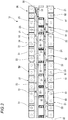
FIG. 2 is a top view of the bus bar module according to the present embodiment. -
FIG. 3 is a perspective view of a bus bar housing portion and a bus bar. -
FIG. 4 is a cross-sectional view of the bus bar module that is fastened and assembled to an electrode of a single cell of the battery assembly by a nut. -
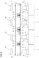
FIG. 5 is a schematic cross-sectional view of the bus bar module that is fastened and assembled to the electrode of the single cell of the battery assembly. -
FIGS. 6A and 6B illustrate a state in which the single cell has shifted in a height direction, in whichFIG. 6A is a schematic cross-sectional view of the bus bar module before being fastened to the electrode, andFIG. 6B is a schematic cross-sectional view of the bus bar module in a state of being fastened to the electrode. -
FIG. 7 is a schematic cross-sectional view of a bus bar module according to a reference example when being fastened in a state in which single cells are shifted in a height direction. - Hereinafter, an embodiment of the present invention will be described with reference to the drawings.
-
FIG. 1 is a perspective view of a bus bar module and a battery assembly according to the present embodiment. - As illustrated in
FIG. 1 , thebus bar module 10 according to the present embodiment is assembled to an upper part of a battery assembly 1 to form apower supply device 2. Thepower supply device 2 is mounted and used on various vehicles which are an electric automobile that travels using an electric motor, a hybrid automobile that travels using an engine and an electric motor in combination, and the like, and is configured to supply power to the electric motor. - The battery assembly 1 includes a plurality of
single cells 3 that are arranged in a row along one direction and are fixed to one another. Eachsingle cell 3 includes a rectangularparallelepiped battery body 4, and a pair ofelectrodes 5 protruding from near one end of an upper surface of thebattery body 4 and from near the other end of the upper surface. One of the pair ofelectrodes 5 is a positive electrode and the other is a negative electrode. - The
single cells 3 are arranged such that thebattery bodies 4 are in contact with one another. In the battery assembly 1, poles of theelectrodes 5 are aligned for every foursingle cells 3 adjacent to one another, and one battery set BS is formed of the foursingle cells 3 in which the poles of theelectrode 5 are aligned. In this example, the battery assembly 1 includes four battery sets BS each including foursingle cells 3, and the battery sets BS of thesingle cells 3 that are adjacent to one another are arranged such that the poles of theelectrodes 5 are alternated. - Each of the pair of
electrodes 5 is formed of a conductive metal. Theelectrode 5 includes a plate-shapedseat plate portion 6 and acolumnar pole post 7 erected at a center of theseat plate portion 6. A male screw is formed on an outer periphery of thepole post 7, and a nut 60 (described below) is fastened thereto. -
FIG. 2 is a top view of the bus bar module according to the present embodiment. - As illustrated in
FIG. 2 , thebus bar module 10 includes acase 20 and abus bar 50. Thebus bar module 10 connects the battery sets BS of thesingle cells 3 in series. - The
case 20 is integrally formed of, for example, a synthetic resin or the like, and includes a plurality of busbar housing portions 21. - The bus
bar housing portions 21 are arranged in two rows along an arrangement direction of the plurality ofsingle cells 3. The busbar housing portion 21 is formed of a frame including aperipheral wall portion 22, and thebus bar 50 is housed in the busbar housing portion 21. - The
case 20 includes twosupport beam portions 24 along the arrangement of the busbar housing portions 21, and the busbar housing portions 21 are connected to and supported by thesupport beam portions 24, respectively. The twosupport beam portions 24 are connected in parallel bybridge portions 25. - One of the
support beam portions 24 is provided with an electric wirerouting groove portion 31. The electric wirerouting groove portion 31 is formed in a gutter shape with an upper side thereof opened. Athermistor mounting portion 28 is formed at an end of the othersupport beam portion 24, and a thermistor (not illustrated) configured to detect a temperature of thesingle cell 3 is mounted on thethermistor mounting portion 28. - The
bridge portion 25 connecting thesupport beam portions 24 is provided with a gutter-shaped electric wirerouting groove portion 32 whose upper side is opened, and the electric wirerouting groove portion 32 is provided continuously with the electric wirerouting groove portion 31. - The bus
bar housing portion 21 and thethermistor mounting portion 28 are provided continuously with gutter-shaped electric wirerouting groove portions 33 whose upper sides are opened. The electric wirerouting groove portion 33 provided continuously with the busbar housing portion 21 in one row is provided continuously with the electric wirerouting groove portion 31 of the one ofsupport beam portions 24, and the electric wirerouting groove portion 33 provided continuously with the busbar housing portion 21 in the other row and thethermistor mounting portion 28 is provided continuously with the electric wirerouting groove portion 32 of thebridge portion 25. - The electric wire
routing groove portions case 20 house an electric wire (not illustrated) for voltage detection electrically connected to thebus bar 50 and an electric wire (not illustrated) extending from the thermistor. These electric wires are led out from an end of the electric wirerouting groove portion 31 of the one of thesupport beam portions 24, and are connected to a circuit board (not illustrated) including a voltage monitoring circuit and a temperature monitoring circuit. -
FIG. 3 is a perspective view of a bus bar housing portion and a bus bar.FIG. 4 is a cross-sectional view of the bus bar module that is fastened and assembled to an electrode of a single cell of the battery assembly by a nut.FIG. 5 is a schematic cross-sectional view of the bus bar module that is fastened and assembled to the electrode of the single cell of the battery assembly. - As illustrated in
FIGS. 3 to 5 , thebus bar 50 housed in the busbar housing portion 21 of thecase 20 is formed to be long. Thebus bar 50 is formed by punching and bending a conductive metal plate. Thebus bar 50 is formed with a plurality of fastening holes 51 as electrical connection portions. These fastening holes 51 are formed at the same pitch as a pitch of theelectrodes 5 along the arrangement direction of thesingle cells 3 of the battery assembly 1. Thefastening hole 51 has an inner diameter slightly larger than an outer diameter of thepole post 7 of theelectrode 5. The pole posts 7 of theelectrodes 5 are inserted through the fastening holes 51. Thenut 60 is screwed and fastened to thepole post 7 of theelectrode 5 passed through thefastening hole 51 of thebus bar 50. Accordingly, an edge of thefastening hole 51 in thebus bar 50 is fastened (fixed) while being interposed between theseat plate portion 6 of theelectrode 5 and thenut 60, and thebus bar 50 and theelectrode 5 are electrically connected. - The
bus bar 50 includes aprojection 52 between the adjacent fastening holes 51. Theprojection 52 is formed in a convex shape protruding upward, and includes a pair ofside plate portions 53 facing each other and anupper plate portion 54 provided continuously with upper edges of theside plate portions 53. - The
peripheral wall portion 22 of the busbar housing portion 21 formed of the frame that houses thebus bar 50 includes a pair oflong side portions 41 and a pair ofshort side portions 42, and theshort side portion 42 is provided continuously with both ends of thelong side portion 41. The busbar housing portion 21 includes a plurality ofsupport portions 43. Thesupport portions 43 are integrally formed being bridged over thelong side portions 41 of theperipheral wall portion 22, and are provided at intervals in a longitudinal direction of the busbar housing portion 21. - The
support portion 43 is formed in a plate shape, and an upper edge thereof is formed in an arc shape as viewed in cross section. Thesupport portion 43 extends in a direction orthogonal to an arrangement direction of the fastening holes 51 of thebus bar 50 housed in the busbar housing portion 21. Thesupport portion 43 is erected on abase portion 45 formed in a plate shape. Thebase portion 45 is formed integrally at a lower edge of thesupport portion 43 while protruding to both sides. Thesupport portion 43 is formed narrower than thebase portion 45. A width W1 of thesupport portion 43 is smaller than an interval W2 between inner side surfaces of theside plate portions 53 of theprojection 52 formed on thebus bar 50. - The
support portion 43 is provided inside theprojection 52 of thebus bar 50 substantially below a center of theprojection 52 in a state in which thebus bar 50 is housed in the busbar housing portion 21 from above. Thesupport portion 43 abuts against a back surface of theupper plate portion 54 of theprojection 52 to support thebus bar 50. In the state in which thebus bar 50 is housed in the busbar housing portion 21, thebase portion 45 is provided above alower surface 50a of thebus bar 50 in a protruding direction of theprojection 52. Accordingly, in the state in which thebus bar 50 is housed in the busbar housing portion 21, thebase portion 45 of thesupport portion 43 is wrapped to thebus bar 50 in a direction in which thebus bar 50 is fastened to theelectrode 5. - The bus
bar housing portion 21 includes a plurality of lockingclaws 46 on thelong side portion 41. When thebus bar 50 has been housed in the busbar housing portion 21 from above, a periphery of thebus bar 50 is locked by the lockingclaws 46. Accordingly, thebus bar 50 is prevented from falling out of the busbar housing portion 21 in a state in which theprojection 52 of thebus bar 50 is supported by thesupport portion 43. - In order to assemble the
bus bar module 10 having the above-described structure to the battery assembly 1, thebus bar module 10 is placed on the upper part of the battery assembly 1, and thepole post 7 of theelectrode 5 of thesingle cell 3 is inserted into thefastening hole 51 of thebus bar 50. - Next, the
nut 60 is screwed and fastened to thepole post 7 of theelectrode 5 inserted into thefastening hole 51 of thebus bar 50. - Accordingly, the edge of the
fastening hole 51 in thebus bar 50 is interposed between theseat plate portion 6 of theelectrode 5 and thenut 60, and thebus bar 50 and theelectrode 5 are electrically connected. - As illustrated in
FIG. 6A , the plurality ofsingle cells 3 of the battery assembly 1 may vary in height position depending on assembled states of the plurality ofsingle cells 3, and a displacement H in the height direction may occur between fastening surfaces which are upper surfaces of theseat plate portions 6 of theadjacent electrodes 5. - However, in the
bus bar module 10 according to the present embodiment, theprojection 52 of thebus bar 50 is elastically deformed, so that it is possible to absorb the displacement H between the fastening surfaces of theadjacent electrodes 5 in the height direction as illustrated inFIG. 6B . - Here, as illustrated in
FIG. 7 , aflat bus bar 50A not including theprojection 52 is fastened to theelectrode 5 of thesingle cell 3, and thelower surface 50a of thebus bar 50 is supported by a plate-shapedsupport portion 43A between the fastening holes 51. - In this structure, when the
bus bar 50A is fastened to theelectrodes 5 by the nuts 60, the fastening state of thebus bar 50A to theelectrodes 5 by the nuts 60 may become unstable due to the displacement H between the fastening surfaces which are the upper surfaces of theseat plate portions 6 of theelectrodes 5 in the height direction. For example, when thebus bar 50A is fastened to ahigh electrode 5, a gap is formed between thebus bar 50A and an upper surface of aseat plate portion 6 of alow electrode 5. Accordingly, a large fastening force is required when thebus bar 50A is fastened to thelow electrode 5 by thenut 60. Therefore, if thenut 60 is fastened to theelectrode 5 with a constant fastening force when the displacement H occurs, thebus bar 50A may be fastened incompletely on thelow electrode 5. - On the other hand, according to the
bus bar module 10 in the present embodiment, when thepole post 7 of theelectrode 5 is inserted into thefastening hole 51 of thebus bar 50 and thenut 60 is screwed to fasten thebus bar 50 to theelectrode 5, theprojection 52 of thebus bar 50 supported on thesupport portion 43 is easily elastically deformed. Therefore, even if the displacement H in an assembling direction of thebus bar 50 occurs between theelectrodes 5 of the adjacentsingle cells 3, it is possible to easily absorb the displacement H by the elastic deformation of theprojection 52. In this case, thesupport portion 43 has a width W1 smaller than an interval W2 between inner side surfaces of theside plate portions 53 of theprojection 52, so that side surfaces of thesupport portion 43 do not abut against the inner surfaces of theside plate portion 53 of theprojection 52, and thus do not prevent the elastic deformation. Accordingly, when thebus bar 50 is connected to theelectrode 5 by thenut 60, it is possible to constantly and stably fasten thebus bar 50 with a predetermined fastening force and to attain good connection reliability. - In addition, the
support portion 43 is in line contact with the back surface of theupper plate portion 54 of theprojection 52 in a direction orthogonal to an arrangement direction of the fastening holes 51. Accordingly, when thebus bar 50 is fastened to theelectrode 5 in a state in which the displacement H in the assembling direction of thebus bar 50 has occurred between theelectrodes 5 of the adjacentsingle cells 3, it is possible to easily incline thebus bar 50 using a part thereof in contact with thesupport portion 43 as a fulcrum. Accordingly, it is possible to more easily absorb the displacement H between theelectrodes 5 of thesingle cells 3. - When the
bus bar 50 is fastened to theelectrodes 5 of thesingle cells 3 with three or more fastening holes 51, the displacement H in the assembling direction of thebus bar 50 is likely to occur among theelectrodes 5 of three or more adjacentsingle cells 3. However, theprojection 52 of thebus bar 50 formed between the fastening holes 51 is supported on thesupport portion 43. Accordingly, even if the displacement H occurs among the electrodes be shifted fastened in the fastening holes 51, it is possible to elastically deform theprojection 52 supported by thesupport portion 43 between the fastening holes 51 to easily absorb the displacement H. - The present invention is not limited to the above-described embodiment, and may be appropriately modified, improved, or the like. In addition, materials, shapes, sizes, numbers, arrangement positions, and the like of components in the above-described embodiment are optional as long as the present invention can be achieved, and the present invention is not limited thereto.
- For example, in the above-described
bus bar 50 according to the embodiment, a case has been described as an example in which the fastening holes 51 are formed as a plurality of electrical connection portions configured to electrically connect and fix the plurality ofelectrodes 5 of thesingle cells 3, and thenut 60 is screwed to be fastened and fixed to thepole post 7 of theelectrode 5 passed through thefastening hole 51. It is needless to say that the electrical connection portion of the bus bar according to the present invention is not limited thereto, and may be a welded portion that is fixed to the electrode by welding. - [1] A bus bar module (10) including:
- a case (20) that is assembled to a battery assembly (1) including a plurality of single cells (3); and
- a bus bar (50) that is supported by the case (20), that is electrically connected to an electrode (5) of the single cell (3) of the battery assembly (1), and that is formed of a conductive metal plate,
- in which the bus bar (50) includes:
- a plurality of electrical connection portions (fastening holes 51) configured to electrically connect and fix a plurality of the electrodes (5) of the single cells (3); and
- a plurality of projections (52) that are each formed between the electrical connection portions (the fastening holes 51) and protrude in a direction away from the single cell (3),
- in which the case (20) includes:
- a bus bar housing portion (21) in which the bus bar (50) is housed; and
- a support portion (43) that is provided in the projection (52) of the bus bar (50) housed in the bus bar housing portion (21) and abuts against a back surface of the projection (52) to support the bus bar (50), and
- in which the support portion (43) has a width (W1) smaller than an interval (W2) between inner side surfaces of side plate portions (53) of the projection (52).
- [2] The bus bar module according to [1],
in which the support portion (43) is in line contact with the back surface of the projection (52) in a direction orthogonal to an arrangement direction of the electrical connection portions (the fastening holes 51). - [3] The bus bar module according to [1] or [2]
in which, in the bus bar (50), three or more electrical connection portions (the fastening holes 51) are formed at equal intervals, and the projections (52) are formed between the electrical connection portions (the fastening holes 51), respectively, and
in which the case (20) includes the support portion (43) corresponding to each of the projections (52) of the bus bar (50) housed in the bus bar housing portion (21).
Claims (3)
- A bus bar module comprising:a case that is assembled to a battery assembly including a plurality of single cells; anda bus bar that is supported by the case and that is formed of a conductive metal plate electrically connected to an electrode of the single cell of the battery assembly,wherein the bus bar includes:a plurality of electrical connection portions configured to electrically connect and fix a plurality of the electrodes of the single cells; anda plurality of projections that are each formed between the electrical connection portions and protrude in a direction away from the single cell,wherein the case includes:a bus bar housing portion in which the bus bar is housed; anda support portion that is provided in the projection of the bus bar housed in the bus bar housing portion and abuts against a back surface of the projection to support the bus bar, andwherein the support portion has a width smaller than an interval between inner side surfaces of side plate portions of the projection.
- The bus bar module according to claim 1,
wherein the support portion is in line contact with the back surface of the projection in a direction orthogonal to an arrangement direction of the electrical connection portions. - The bus bar module according to claim 1 or 2,
wherein, in the bus bar, three or more electrical connection portions are formed at equal intervals, and the projections are formed between the electrical connection portions, respectively, and
wherein the case includes the support portion corresponding to each of the projections of the bus bar housed in the bus bar housing portion.
Applications Claiming Priority (1)
| Application Number | Priority Date | Filing Date | Title |
|---|---|---|---|
| JP2019112848A JP7132178B2 (en) | 2019-06-18 | 2019-06-18 | busbar module |
Publications (2)
| Publication Number | Publication Date |
|---|---|
| EP3754746A1 true EP3754746A1 (en) | 2020-12-23 |
| EP3754746B1 EP3754746B1 (en) | 2023-03-22 |
Family
ID=71096586
Family Applications (1)
| Application Number | Title | Priority Date | Filing Date |
|---|---|---|---|
| EP20180002.6A Active EP3754746B1 (en) | 2019-06-18 | 2020-06-15 | Bus bar module |
Country Status (4)
| Country | Link |
|---|---|
| US (1) | US11367930B2 (en) |
| EP (1) | EP3754746B1 (en) |
| JP (1) | JP7132178B2 (en) |
| CN (1) | CN112103453B (en) |
Citations (4)
| Publication number | Priority date | Publication date | Assignee | Title |
|---|---|---|---|---|
| US20040043663A1 (en) * | 2002-08-30 | 2004-03-04 | Yazaki Corporation | Battery connecting plate, and attachment structure of the same |
| JP2011065863A (en) | 2009-09-17 | 2011-03-31 | Yazaki Corp | Wire arrangement body, busbar module and power supply unit |
| EP2461392A2 (en) * | 2010-11-05 | 2012-06-06 | SB LiMotive Co., Ltd. | Battery module |
| US20170288183A1 (en) * | 2014-09-03 | 2017-10-05 | Kabushiki Kaisha Toyota Jidoshokki | Battery module |
Family Cites Families (8)
| Publication number | Priority date | Publication date | Assignee | Title |
|---|---|---|---|---|
| JP3848565B2 (en) * | 2001-11-27 | 2006-11-22 | 松下電器産業株式会社 | Battery connection structure, battery module, and battery pack |
| US8313855B2 (en) * | 2007-08-02 | 2012-11-20 | Johnson Controls—SAFT Advanced Power Solutions LLC | Interconnection washer assembly for a battery assembly |
| JP5500364B2 (en) * | 2010-06-10 | 2014-05-21 | 株式会社オートネットワーク技術研究所 | Battery connection assembly |
| JP5834769B2 (en) * | 2011-10-26 | 2015-12-24 | 株式会社オートネットワーク技術研究所 | Battery wiring module |
| JP6062266B2 (en) * | 2013-01-30 | 2017-01-18 | 矢崎総業株式会社 | Bus bar module and power supply |
| JP6653295B2 (en) * | 2017-08-03 | 2020-02-26 | 矢崎総業株式会社 | Busbar module electrode contact structure |
| JP6691083B2 (en) * | 2017-08-30 | 2020-04-28 | 矢崎総業株式会社 | Bus bar, bus bar module, and battery pack |
| JP7346057B2 (en) * | 2019-03-28 | 2023-09-19 | パナソニックエナジー株式会社 | battery pack |
-
2019
- 2019-06-18 JP JP2019112848A patent/JP7132178B2/en active Active
-
2020
- 2020-06-15 EP EP20180002.6A patent/EP3754746B1/en active Active
- 2020-06-17 US US16/903,391 patent/US11367930B2/en active Active
- 2020-06-17 CN CN202010552492.0A patent/CN112103453B/en active Active
Patent Citations (4)
| Publication number | Priority date | Publication date | Assignee | Title |
|---|---|---|---|---|
| US20040043663A1 (en) * | 2002-08-30 | 2004-03-04 | Yazaki Corporation | Battery connecting plate, and attachment structure of the same |
| JP2011065863A (en) | 2009-09-17 | 2011-03-31 | Yazaki Corp | Wire arrangement body, busbar module and power supply unit |
| EP2461392A2 (en) * | 2010-11-05 | 2012-06-06 | SB LiMotive Co., Ltd. | Battery module |
| US20170288183A1 (en) * | 2014-09-03 | 2017-10-05 | Kabushiki Kaisha Toyota Jidoshokki | Battery module |
Also Published As
| Publication number | Publication date |
|---|---|
| EP3754746B1 (en) | 2023-03-22 |
| US20200403208A1 (en) | 2020-12-24 |
| CN112103453B (en) | 2023-04-07 |
| CN112103453A (en) | 2020-12-18 |
| JP2020205184A (en) | 2020-12-24 |
| JP7132178B2 (en) | 2022-09-06 |
| US11367930B2 (en) | 2022-06-21 |
Similar Documents
| Publication | Publication Date | Title |
|---|---|---|
| US9871361B2 (en) | Busbar holding structure | |
| JP6679282B2 (en) | Holding structure for voltage detection terminals | |
| US9564661B2 (en) | Battery module and wiring module | |
| JP6587598B2 (en) | Voltage detection terminal holding structure | |
| US20160035497A1 (en) | Electrical Storage Module | |
| WO2011108511A1 (en) | Battery connection assembly | |
| JP2015138604A (en) | wiring module | |
| US20150140409A1 (en) | Electricity storage module and electricity storage cell | |
| JP2013037878A (en) | Cover of battery wiring module, and battery wiring module | |
| CN109075308B (en) | Connection module | |
| JP7256079B2 (en) | Electric wire holding structure and busbar module | |
| US11532856B2 (en) | Electric wire holding structure and bus bar module | |
| CN109390539B (en) | Electrode contact structure of bus bar module | |
| CN112106226A (en) | Electricity storage device | |
| JP5521639B2 (en) | Battery connection assembly | |
| EP3754747A1 (en) | Bus bar module | |
| EP3754746B1 (en) | Bus bar module | |
| JP2021111502A (en) | Bus bar module | |
| JP2012252782A (en) | Battery wiring module | |
| JP2021136163A (en) | Bus bar module | |
| CN116583996A (en) | Battery module having improved wire-bonding connection structure between bus bar plate and ICB assembly, and battery pack including the same | |
| JP2021136162A (en) | Bus bar module | |
| JP2017216124A (en) | Secondary battery module |
Legal Events
| Date | Code | Title | Description |
|---|---|---|---|
| PUAI | Public reference made under article 153(3) epc to a published international application that has entered the european phase |
Free format text: ORIGINAL CODE: 0009012 |
|
| STAA | Information on the status of an ep patent application or granted ep patent |
Free format text: STATUS: REQUEST FOR EXAMINATION WAS MADE |
|
| 17P | Request for examination filed |
Effective date: 20200615 |
|
| AK | Designated contracting states |
Kind code of ref document: A1 Designated state(s): AL AT BE BG CH CY CZ DE DK EE ES FI FR GB GR HR HU IE IS IT LI LT LU LV MC MK MT NL NO PL PT RO RS SE SI SK SM TR |
|
| AX | Request for extension of the european patent |
Extension state: BA ME |
|
| STAA | Information on the status of an ep patent application or granted ep patent |
Free format text: STATUS: EXAMINATION IS IN PROGRESS |
|
| 17Q | First examination report despatched |
Effective date: 20220228 |
|
| REG | Reference to a national code |
Ref country code: DE Ref legal event code: R079 Ref document number: 602020008961 Country of ref document: DE Free format text: PREVIOUS MAIN CLASS: H01M0002100000 Ipc: H01M0010480000 |
|
| GRAP | Despatch of communication of intention to grant a patent |
Free format text: ORIGINAL CODE: EPIDOSNIGR1 |
|
| STAA | Information on the status of an ep patent application or granted ep patent |
Free format text: STATUS: GRANT OF PATENT IS INTENDED |
|
| RIC1 | Information provided on ipc code assigned before grant |
Ipc: H01M 50/524 20210101ALI20221125BHEP Ipc: H01M 50/522 20210101ALI20221125BHEP Ipc: H01M 50/517 20210101ALI20221125BHEP Ipc: H01M 50/507 20210101ALI20221125BHEP Ipc: H01M 50/209 20210101ALI20221125BHEP Ipc: H01M 10/48 20060101AFI20221125BHEP |
|
| INTG | Intention to grant announced |
Effective date: 20230103 |
|
| GRAS | Grant fee paid |
Free format text: ORIGINAL CODE: EPIDOSNIGR3 |
|
| GRAA | (expected) grant |
Free format text: ORIGINAL CODE: 0009210 |
|
| STAA | Information on the status of an ep patent application or granted ep patent |
Free format text: STATUS: THE PATENT HAS BEEN GRANTED |
|
| AK | Designated contracting states |
Kind code of ref document: B1 Designated state(s): AL AT BE BG CH CY CZ DE DK EE ES FI FR GB GR HR HU IE IS IT LI LT LU LV MC MK MT NL NO PL PT RO RS SE SI SK SM TR |
|
| REG | Reference to a national code |
Ref country code: GB Ref legal event code: FG4D |
|
| REG | Reference to a national code |
Ref country code: CH Ref legal event code: EP |
|
| REG | Reference to a national code |
Ref country code: DE Ref legal event code: R096 Ref document number: 602020008961 Country of ref document: DE |
|
| REG | Reference to a national code |
Ref country code: IE Ref legal event code: FG4D |
|
| REG | Reference to a national code |
Ref country code: AT Ref legal event code: REF Ref document number: 1555854 Country of ref document: AT Kind code of ref document: T Effective date: 20230415 |
|
| RAP4 | Party data changed (patent owner data changed or rights of a patent transferred) |
Owner name: YAZAKI CORPORATION |
|
| REG | Reference to a national code |
Ref country code: LT Ref legal event code: MG9D |
|
| REG | Reference to a national code |
Ref country code: NL Ref legal event code: MP Effective date: 20230322 |
|
| PG25 | Lapsed in a contracting state [announced via postgrant information from national office to epo] |
Ref country code: RS Free format text: LAPSE BECAUSE OF FAILURE TO SUBMIT A TRANSLATION OF THE DESCRIPTION OR TO PAY THE FEE WITHIN THE PRESCRIBED TIME-LIMIT Effective date: 20230322 Ref country code: NO Free format text: LAPSE BECAUSE OF FAILURE TO SUBMIT A TRANSLATION OF THE DESCRIPTION OR TO PAY THE FEE WITHIN THE PRESCRIBED TIME-LIMIT Effective date: 20230622 Ref country code: LV Free format text: LAPSE BECAUSE OF FAILURE TO SUBMIT A TRANSLATION OF THE DESCRIPTION OR TO PAY THE FEE WITHIN THE PRESCRIBED TIME-LIMIT Effective date: 20230322 Ref country code: LT Free format text: LAPSE BECAUSE OF FAILURE TO SUBMIT A TRANSLATION OF THE DESCRIPTION OR TO PAY THE FEE WITHIN THE PRESCRIBED TIME-LIMIT Effective date: 20230322 Ref country code: HR Free format text: LAPSE BECAUSE OF FAILURE TO SUBMIT A TRANSLATION OF THE DESCRIPTION OR TO PAY THE FEE WITHIN THE PRESCRIBED TIME-LIMIT Effective date: 20230322 |
|
| PGFP | Annual fee paid to national office [announced via postgrant information from national office to epo] |
Ref country code: DE Payment date: 20230516 Year of fee payment: 4 |
|
| REG | Reference to a national code |
Ref country code: AT Ref legal event code: MK05 Ref document number: 1555854 Country of ref document: AT Kind code of ref document: T Effective date: 20230322 |
|
| PG25 | Lapsed in a contracting state [announced via postgrant information from national office to epo] |
Ref country code: SE Free format text: LAPSE BECAUSE OF FAILURE TO SUBMIT A TRANSLATION OF THE DESCRIPTION OR TO PAY THE FEE WITHIN THE PRESCRIBED TIME-LIMIT Effective date: 20230322 Ref country code: NL Free format text: LAPSE BECAUSE OF FAILURE TO SUBMIT A TRANSLATION OF THE DESCRIPTION OR TO PAY THE FEE WITHIN THE PRESCRIBED TIME-LIMIT Effective date: 20230322 Ref country code: GR Free format text: LAPSE BECAUSE OF FAILURE TO SUBMIT A TRANSLATION OF THE DESCRIPTION OR TO PAY THE FEE WITHIN THE PRESCRIBED TIME-LIMIT Effective date: 20230623 Ref country code: FI Free format text: LAPSE BECAUSE OF FAILURE TO SUBMIT A TRANSLATION OF THE DESCRIPTION OR TO PAY THE FEE WITHIN THE PRESCRIBED TIME-LIMIT Effective date: 20230322 |
|
| PG25 | Lapsed in a contracting state [announced via postgrant information from national office to epo] |
Ref country code: SM Free format text: LAPSE BECAUSE OF FAILURE TO SUBMIT A TRANSLATION OF THE DESCRIPTION OR TO PAY THE FEE WITHIN THE PRESCRIBED TIME-LIMIT Effective date: 20230322 Ref country code: RO Free format text: LAPSE BECAUSE OF FAILURE TO SUBMIT A TRANSLATION OF THE DESCRIPTION OR TO PAY THE FEE WITHIN THE PRESCRIBED TIME-LIMIT Effective date: 20230322 Ref country code: PT Free format text: LAPSE BECAUSE OF FAILURE TO SUBMIT A TRANSLATION OF THE DESCRIPTION OR TO PAY THE FEE WITHIN THE PRESCRIBED TIME-LIMIT Effective date: 20230724 Ref country code: ES Free format text: LAPSE BECAUSE OF FAILURE TO SUBMIT A TRANSLATION OF THE DESCRIPTION OR TO PAY THE FEE WITHIN THE PRESCRIBED TIME-LIMIT Effective date: 20230322 Ref country code: EE Free format text: LAPSE BECAUSE OF FAILURE TO SUBMIT A TRANSLATION OF THE DESCRIPTION OR TO PAY THE FEE WITHIN THE PRESCRIBED TIME-LIMIT Effective date: 20230322 Ref country code: AT Free format text: LAPSE BECAUSE OF FAILURE TO SUBMIT A TRANSLATION OF THE DESCRIPTION OR TO PAY THE FEE WITHIN THE PRESCRIBED TIME-LIMIT Effective date: 20230322 |
|
| PG25 | Lapsed in a contracting state [announced via postgrant information from national office to epo] |
Ref country code: SK Free format text: LAPSE BECAUSE OF FAILURE TO SUBMIT A TRANSLATION OF THE DESCRIPTION OR TO PAY THE FEE WITHIN THE PRESCRIBED TIME-LIMIT Effective date: 20230322 Ref country code: PL Free format text: LAPSE BECAUSE OF FAILURE TO SUBMIT A TRANSLATION OF THE DESCRIPTION OR TO PAY THE FEE WITHIN THE PRESCRIBED TIME-LIMIT Effective date: 20230322 Ref country code: IS Free format text: LAPSE BECAUSE OF FAILURE TO SUBMIT A TRANSLATION OF THE DESCRIPTION OR TO PAY THE FEE WITHIN THE PRESCRIBED TIME-LIMIT Effective date: 20230722 |
|
| REG | Reference to a national code |
Ref country code: DE Ref legal event code: R097 Ref document number: 602020008961 Country of ref document: DE |
|
| PG25 | Lapsed in a contracting state [announced via postgrant information from national office to epo] |
Ref country code: MC Free format text: LAPSE BECAUSE OF FAILURE TO SUBMIT A TRANSLATION OF THE DESCRIPTION OR TO PAY THE FEE WITHIN THE PRESCRIBED TIME-LIMIT Effective date: 20230322 |
|
| PLBE | No opposition filed within time limit |
Free format text: ORIGINAL CODE: 0009261 |
|
| STAA | Information on the status of an ep patent application or granted ep patent |
Free format text: STATUS: NO OPPOSITION FILED WITHIN TIME LIMIT |
|
| PG25 | Lapsed in a contracting state [announced via postgrant information from national office to epo] |
Ref country code: SI Free format text: LAPSE BECAUSE OF FAILURE TO SUBMIT A TRANSLATION OF THE DESCRIPTION OR TO PAY THE FEE WITHIN THE PRESCRIBED TIME-LIMIT Effective date: 20230322 Ref country code: MC Free format text: LAPSE BECAUSE OF FAILURE TO SUBMIT A TRANSLATION OF THE DESCRIPTION OR TO PAY THE FEE WITHIN THE PRESCRIBED TIME-LIMIT Effective date: 20230322 Ref country code: DK Free format text: LAPSE BECAUSE OF FAILURE TO SUBMIT A TRANSLATION OF THE DESCRIPTION OR TO PAY THE FEE WITHIN THE PRESCRIBED TIME-LIMIT Effective date: 20230322 Ref country code: CZ Free format text: LAPSE BECAUSE OF FAILURE TO SUBMIT A TRANSLATION OF THE DESCRIPTION OR TO PAY THE FEE WITHIN THE PRESCRIBED TIME-LIMIT Effective date: 20230322 |
|
| REG | Reference to a national code |
Ref country code: CH Ref legal event code: PL |
|
| REG | Reference to a national code |
Ref country code: BE Ref legal event code: MM Effective date: 20230630 |
|
| 26N | No opposition filed |
Effective date: 20240102 |
|
| PG25 | Lapsed in a contracting state [announced via postgrant information from national office to epo] |
Ref country code: LU Free format text: LAPSE BECAUSE OF NON-PAYMENT OF DUE FEES Effective date: 20230615 |
|
| REG | Reference to a national code |
Ref country code: IE Ref legal event code: MM4A |
|
| PG25 | Lapsed in a contracting state [announced via postgrant information from national office to epo] |
Ref country code: LU Free format text: LAPSE BECAUSE OF NON-PAYMENT OF DUE FEES Effective date: 20230615 |
|
| PG25 | Lapsed in a contracting state [announced via postgrant information from national office to epo] |
Ref country code: IE Free format text: LAPSE BECAUSE OF NON-PAYMENT OF DUE FEES Effective date: 20230615 |