EP3754741A1 - Pouch type secondary battery and method for manufacturing same - Google Patents
Pouch type secondary battery and method for manufacturing same Download PDFInfo
- Publication number
- EP3754741A1 EP3754741A1 EP19899199.4A EP19899199A EP3754741A1 EP 3754741 A1 EP3754741 A1 EP 3754741A1 EP 19899199 A EP19899199 A EP 19899199A EP 3754741 A1 EP3754741 A1 EP 3754741A1
- Authority
- EP
- European Patent Office
- Prior art keywords
- coating layer
- case
- lower case
- upper case
- sealing portion
- Prior art date
- Legal status (The legal status is an assumption and is not a legal conclusion. Google has not performed a legal analysis and makes no representation as to the accuracy of the status listed.)
- Granted
Links
Images


Classifications
-
- H—ELECTRICITY
- H01—ELECTRIC ELEMENTS
- H01M—PROCESSES OR MEANS, e.g. BATTERIES, FOR THE DIRECT CONVERSION OF CHEMICAL ENERGY INTO ELECTRICAL ENERGY
- H01M50/00—Constructional details or processes of manufacture of the non-active parts of electrochemical cells other than fuel cells, e.g. hybrid cells
- H01M50/10—Primary casings; Jackets or wrappings
- H01M50/116—Primary casings; Jackets or wrappings characterised by the material
- H01M50/124—Primary casings; Jackets or wrappings characterised by the material having a layered structure
- H01M50/126—Primary casings; Jackets or wrappings characterised by the material having a layered structure comprising three or more layers
- H01M50/129—Primary casings; Jackets or wrappings characterised by the material having a layered structure comprising three or more layers with two or more layers of only organic material
-
- H—ELECTRICITY
- H01—ELECTRIC ELEMENTS
- H01M—PROCESSES OR MEANS, e.g. BATTERIES, FOR THE DIRECT CONVERSION OF CHEMICAL ENERGY INTO ELECTRICAL ENERGY
- H01M50/00—Constructional details or processes of manufacture of the non-active parts of electrochemical cells other than fuel cells, e.g. hybrid cells
- H01M50/10—Primary casings; Jackets or wrappings
- H01M50/183—Sealing members
-
- B—PERFORMING OPERATIONS; TRANSPORTING
- B29—WORKING OF PLASTICS; WORKING OF SUBSTANCES IN A PLASTIC STATE IN GENERAL
- B29C—SHAPING OR JOINING OF PLASTICS; SHAPING OF MATERIAL IN A PLASTIC STATE, NOT OTHERWISE PROVIDED FOR; AFTER-TREATMENT OF THE SHAPED PRODUCTS, e.g. REPAIRING
- B29C66/00—General aspects of processes or apparatus for joining preformed parts
- B29C66/40—General aspects of joining substantially flat articles, e.g. plates, sheets or web-like materials; Making flat seams in tubular or hollow articles; Joining single elements to substantially flat surfaces
- B29C66/41—Joining substantially flat articles ; Making flat seams in tubular or hollow articles
- B29C66/43—Joining a relatively small portion of the surface of said articles
- B29C66/432—Joining a relatively small portion of the surface of said articles for making tubular articles or closed loops, e.g. by joining several sheets ; for making hollow articles or hollow preforms
-
- H—ELECTRICITY
- H01—ELECTRIC ELEMENTS
- H01M—PROCESSES OR MEANS, e.g. BATTERIES, FOR THE DIRECT CONVERSION OF CHEMICAL ENERGY INTO ELECTRICAL ENERGY
- H01M10/00—Secondary cells; Manufacture thereof
- H01M10/04—Construction or manufacture in general
-
- H—ELECTRICITY
- H01—ELECTRIC ELEMENTS
- H01M—PROCESSES OR MEANS, e.g. BATTERIES, FOR THE DIRECT CONVERSION OF CHEMICAL ENERGY INTO ELECTRICAL ENERGY
- H01M50/00—Constructional details or processes of manufacture of the non-active parts of electrochemical cells other than fuel cells, e.g. hybrid cells
- H01M50/10—Primary casings; Jackets or wrappings
- H01M50/102—Primary casings; Jackets or wrappings characterised by their shape or physical structure
- H01M50/105—Pouches or flexible bags
-
- H—ELECTRICITY
- H01—ELECTRIC ELEMENTS
- H01M—PROCESSES OR MEANS, e.g. BATTERIES, FOR THE DIRECT CONVERSION OF CHEMICAL ENERGY INTO ELECTRICAL ENERGY
- H01M50/00—Constructional details or processes of manufacture of the non-active parts of electrochemical cells other than fuel cells, e.g. hybrid cells
- H01M50/10—Primary casings; Jackets or wrappings
- H01M50/116—Primary casings; Jackets or wrappings characterised by the material
- H01M50/117—Inorganic material
- H01M50/119—Metals
-
- H—ELECTRICITY
- H01—ELECTRIC ELEMENTS
- H01M—PROCESSES OR MEANS, e.g. BATTERIES, FOR THE DIRECT CONVERSION OF CHEMICAL ENERGY INTO ELECTRICAL ENERGY
- H01M50/00—Constructional details or processes of manufacture of the non-active parts of electrochemical cells other than fuel cells, e.g. hybrid cells
- H01M50/10—Primary casings; Jackets or wrappings
- H01M50/116—Primary casings; Jackets or wrappings characterised by the material
- H01M50/121—Organic material
-
- H—ELECTRICITY
- H01—ELECTRIC ELEMENTS
- H01M—PROCESSES OR MEANS, e.g. BATTERIES, FOR THE DIRECT CONVERSION OF CHEMICAL ENERGY INTO ELECTRICAL ENERGY
- H01M50/00—Constructional details or processes of manufacture of the non-active parts of electrochemical cells other than fuel cells, e.g. hybrid cells
- H01M50/10—Primary casings; Jackets or wrappings
- H01M50/116—Primary casings; Jackets or wrappings characterised by the material
- H01M50/124—Primary casings; Jackets or wrappings characterised by the material having a layered structure
- H01M50/1245—Primary casings; Jackets or wrappings characterised by the material having a layered structure characterised by the external coating on the casing
-
- H—ELECTRICITY
- H01—ELECTRIC ELEMENTS
- H01M—PROCESSES OR MEANS, e.g. BATTERIES, FOR THE DIRECT CONVERSION OF CHEMICAL ENERGY INTO ELECTRICAL ENERGY
- H01M50/00—Constructional details or processes of manufacture of the non-active parts of electrochemical cells other than fuel cells, e.g. hybrid cells
- H01M50/10—Primary casings; Jackets or wrappings
- H01M50/14—Primary casings; Jackets or wrappings for protecting against damage caused by external factors
- H01M50/141—Primary casings; Jackets or wrappings for protecting against damage caused by external factors for protecting against humidity
-
- H—ELECTRICITY
- H01—ELECTRIC ELEMENTS
- H01M—PROCESSES OR MEANS, e.g. BATTERIES, FOR THE DIRECT CONVERSION OF CHEMICAL ENERGY INTO ELECTRICAL ENERGY
- H01M50/00—Constructional details or processes of manufacture of the non-active parts of electrochemical cells other than fuel cells, e.g. hybrid cells
- H01M50/10—Primary casings; Jackets or wrappings
- H01M50/183—Sealing members
- H01M50/186—Sealing members characterised by the disposition of the sealing members
-
- H—ELECTRICITY
- H01—ELECTRIC ELEMENTS
- H01M—PROCESSES OR MEANS, e.g. BATTERIES, FOR THE DIRECT CONVERSION OF CHEMICAL ENERGY INTO ELECTRICAL ENERGY
- H01M50/00—Constructional details or processes of manufacture of the non-active parts of electrochemical cells other than fuel cells, e.g. hybrid cells
- H01M50/10—Primary casings; Jackets or wrappings
- H01M50/183—Sealing members
- H01M50/19—Sealing members characterised by the material
- H01M50/193—Organic material
-
- B—PERFORMING OPERATIONS; TRANSPORTING
- B05—SPRAYING OR ATOMISING IN GENERAL; APPLYING FLUENT MATERIALS TO SURFACES, IN GENERAL
- B05D—PROCESSES FOR APPLYING FLUENT MATERIALS TO SURFACES, IN GENERAL
- B05D1/00—Processes for applying liquids or other fluent materials
- B05D1/02—Processes for applying liquids or other fluent materials performed by spraying
-
- B—PERFORMING OPERATIONS; TRANSPORTING
- B05—SPRAYING OR ATOMISING IN GENERAL; APPLYING FLUENT MATERIALS TO SURFACES, IN GENERAL
- B05D—PROCESSES FOR APPLYING FLUENT MATERIALS TO SURFACES, IN GENERAL
- B05D2503/00—Polyurethanes
-
- B—PERFORMING OPERATIONS; TRANSPORTING
- B05—SPRAYING OR ATOMISING IN GENERAL; APPLYING FLUENT MATERIALS TO SURFACES, IN GENERAL
- B05D—PROCESSES FOR APPLYING FLUENT MATERIALS TO SURFACES, IN GENERAL
- B05D2505/00—Polyamides
- B05D2505/50—Polyimides
-
- B—PERFORMING OPERATIONS; TRANSPORTING
- B05—SPRAYING OR ATOMISING IN GENERAL; APPLYING FLUENT MATERIALS TO SURFACES, IN GENERAL
- B05D—PROCESSES FOR APPLYING FLUENT MATERIALS TO SURFACES, IN GENERAL
- B05D2507/00—Polyolefins
- B05D2507/01—Polyethylene
-
- B—PERFORMING OPERATIONS; TRANSPORTING
- B05—SPRAYING OR ATOMISING IN GENERAL; APPLYING FLUENT MATERIALS TO SURFACES, IN GENERAL
- B05D—PROCESSES FOR APPLYING FLUENT MATERIALS TO SURFACES, IN GENERAL
- B05D2507/00—Polyolefins
- B05D2507/02—Polypropylene
-
- B—PERFORMING OPERATIONS; TRANSPORTING
- B29—WORKING OF PLASTICS; WORKING OF SUBSTANCES IN A PLASTIC STATE IN GENERAL
- B29C—SHAPING OR JOINING OF PLASTICS; SHAPING OF MATERIAL IN A PLASTIC STATE, NOT OTHERWISE PROVIDED FOR; AFTER-TREATMENT OF THE SHAPED PRODUCTS, e.g. REPAIRING
- B29C65/00—Joining or sealing of preformed parts, e.g. welding of plastics materials; Apparatus therefor
- B29C65/02—Joining or sealing of preformed parts, e.g. welding of plastics materials; Apparatus therefor by heating, with or without pressure
-
- B—PERFORMING OPERATIONS; TRANSPORTING
- B29—WORKING OF PLASTICS; WORKING OF SUBSTANCES IN A PLASTIC STATE IN GENERAL
- B29C—SHAPING OR JOINING OF PLASTICS; SHAPING OF MATERIAL IN A PLASTIC STATE, NOT OTHERWISE PROVIDED FOR; AFTER-TREATMENT OF THE SHAPED PRODUCTS, e.g. REPAIRING
- B29C66/00—General aspects of processes or apparatus for joining preformed parts
- B29C66/01—General aspects dealing with the joint area or with the area to be joined
- B29C66/03—After-treatments in the joint area
- B29C66/038—Covering the joint by a coating material
- B29C66/0382—Covering the joint by a coating material the coating material being in liquid or paste form
-
- B—PERFORMING OPERATIONS; TRANSPORTING
- B29—WORKING OF PLASTICS; WORKING OF SUBSTANCES IN A PLASTIC STATE IN GENERAL
- B29C—SHAPING OR JOINING OF PLASTICS; SHAPING OF MATERIAL IN A PLASTIC STATE, NOT OTHERWISE PROVIDED FOR; AFTER-TREATMENT OF THE SHAPED PRODUCTS, e.g. REPAIRING
- B29C66/00—General aspects of processes or apparatus for joining preformed parts
- B29C66/01—General aspects dealing with the joint area or with the area to be joined
- B29C66/05—Particular design of joint configurations
- B29C66/10—Particular design of joint configurations particular design of the joint cross-sections
- B29C66/11—Joint cross-sections comprising a single joint-segment, i.e. one of the parts to be joined comprising a single joint-segment in the joint cross-section
- B29C66/112—Single lapped joints
- B29C66/1122—Single lap to lap joints, i.e. overlap joints
-
- B—PERFORMING OPERATIONS; TRANSPORTING
- B29—WORKING OF PLASTICS; WORKING OF SUBSTANCES IN A PLASTIC STATE IN GENERAL
- B29C—SHAPING OR JOINING OF PLASTICS; SHAPING OF MATERIAL IN A PLASTIC STATE, NOT OTHERWISE PROVIDED FOR; AFTER-TREATMENT OF THE SHAPED PRODUCTS, e.g. REPAIRING
- B29C66/00—General aspects of processes or apparatus for joining preformed parts
- B29C66/01—General aspects dealing with the joint area or with the area to be joined
- B29C66/05—Particular design of joint configurations
- B29C66/10—Particular design of joint configurations particular design of the joint cross-sections
- B29C66/13—Single flanged joints; Fin-type joints; Single hem joints; Edge joints; Interpenetrating fingered joints; Other specific particular designs of joint cross-sections not provided for in groups B29C66/11 - B29C66/12
- B29C66/133—Fin-type joints, the parts to be joined being flexible
-
- B—PERFORMING OPERATIONS; TRANSPORTING
- B29—WORKING OF PLASTICS; WORKING OF SUBSTANCES IN A PLASTIC STATE IN GENERAL
- B29C—SHAPING OR JOINING OF PLASTICS; SHAPING OF MATERIAL IN A PLASTIC STATE, NOT OTHERWISE PROVIDED FOR; AFTER-TREATMENT OF THE SHAPED PRODUCTS, e.g. REPAIRING
- B29C66/00—General aspects of processes or apparatus for joining preformed parts
- B29C66/01—General aspects dealing with the joint area or with the area to be joined
- B29C66/05—Particular design of joint configurations
- B29C66/10—Particular design of joint configurations particular design of the joint cross-sections
- B29C66/13—Single flanged joints; Fin-type joints; Single hem joints; Edge joints; Interpenetrating fingered joints; Other specific particular designs of joint cross-sections not provided for in groups B29C66/11 - B29C66/12
- B29C66/137—Beaded-edge joints or bead seals
-
- B—PERFORMING OPERATIONS; TRANSPORTING
- B29—WORKING OF PLASTICS; WORKING OF SUBSTANCES IN A PLASTIC STATE IN GENERAL
- B29C—SHAPING OR JOINING OF PLASTICS; SHAPING OF MATERIAL IN A PLASTIC STATE, NOT OTHERWISE PROVIDED FOR; AFTER-TREATMENT OF THE SHAPED PRODUCTS, e.g. REPAIRING
- B29C66/00—General aspects of processes or apparatus for joining preformed parts
- B29C66/40—General aspects of joining substantially flat articles, e.g. plates, sheets or web-like materials; Making flat seams in tubular or hollow articles; Joining single elements to substantially flat surfaces
- B29C66/41—Joining substantially flat articles ; Making flat seams in tubular or hollow articles
- B29C66/43—Joining a relatively small portion of the surface of said articles
- B29C66/433—Casing-in, i.e. enclosing an element between two sheets by an outlined seam
-
- B—PERFORMING OPERATIONS; TRANSPORTING
- B29—WORKING OF PLASTICS; WORKING OF SUBSTANCES IN A PLASTIC STATE IN GENERAL
- B29C—SHAPING OR JOINING OF PLASTICS; SHAPING OF MATERIAL IN A PLASTIC STATE, NOT OTHERWISE PROVIDED FOR; AFTER-TREATMENT OF THE SHAPED PRODUCTS, e.g. REPAIRING
- B29C66/00—General aspects of processes or apparatus for joining preformed parts
- B29C66/70—General aspects of processes or apparatus for joining preformed parts characterised by the composition, physical properties or the structure of the material of the parts to be joined; Joining with non-plastics material
- B29C66/71—General aspects of processes or apparatus for joining preformed parts characterised by the composition, physical properties or the structure of the material of the parts to be joined; Joining with non-plastics material characterised by the composition of the plastics material of the parts to be joined
-
- B—PERFORMING OPERATIONS; TRANSPORTING
- B29—WORKING OF PLASTICS; WORKING OF SUBSTANCES IN A PLASTIC STATE IN GENERAL
- B29C—SHAPING OR JOINING OF PLASTICS; SHAPING OF MATERIAL IN A PLASTIC STATE, NOT OTHERWISE PROVIDED FOR; AFTER-TREATMENT OF THE SHAPED PRODUCTS, e.g. REPAIRING
- B29C66/00—General aspects of processes or apparatus for joining preformed parts
- B29C66/70—General aspects of processes or apparatus for joining preformed parts characterised by the composition, physical properties or the structure of the material of the parts to be joined; Joining with non-plastics material
- B29C66/72—General aspects of processes or apparatus for joining preformed parts characterised by the composition, physical properties or the structure of the material of the parts to be joined; Joining with non-plastics material characterised by the structure of the material of the parts to be joined
- B29C66/723—General aspects of processes or apparatus for joining preformed parts characterised by the composition, physical properties or the structure of the material of the parts to be joined; Joining with non-plastics material characterised by the structure of the material of the parts to be joined being multi-layered
- B29C66/7232—General aspects of processes or apparatus for joining preformed parts characterised by the composition, physical properties or the structure of the material of the parts to be joined; Joining with non-plastics material characterised by the structure of the material of the parts to be joined being multi-layered comprising a non-plastics layer
- B29C66/72321—General aspects of processes or apparatus for joining preformed parts characterised by the composition, physical properties or the structure of the material of the parts to be joined; Joining with non-plastics material characterised by the structure of the material of the parts to be joined being multi-layered comprising a non-plastics layer consisting of metals or their alloys
-
- B—PERFORMING OPERATIONS; TRANSPORTING
- B29—WORKING OF PLASTICS; WORKING OF SUBSTANCES IN A PLASTIC STATE IN GENERAL
- B29C—SHAPING OR JOINING OF PLASTICS; SHAPING OF MATERIAL IN A PLASTIC STATE, NOT OTHERWISE PROVIDED FOR; AFTER-TREATMENT OF THE SHAPED PRODUCTS, e.g. REPAIRING
- B29C66/00—General aspects of processes or apparatus for joining preformed parts
- B29C66/70—General aspects of processes or apparatus for joining preformed parts characterised by the composition, physical properties or the structure of the material of the parts to be joined; Joining with non-plastics material
- B29C66/73—General aspects of processes or apparatus for joining preformed parts characterised by the composition, physical properties or the structure of the material of the parts to be joined; Joining with non-plastics material characterised by the intensive physical properties of the material of the parts to be joined, by the optical properties of the material of the parts to be joined, by the extensive physical properties of the parts to be joined, by the state of the material of the parts to be joined or by the material of the parts to be joined being a thermoplastic or a thermoset
- B29C66/739—General aspects of processes or apparatus for joining preformed parts characterised by the composition, physical properties or the structure of the material of the parts to be joined; Joining with non-plastics material characterised by the intensive physical properties of the material of the parts to be joined, by the optical properties of the material of the parts to be joined, by the extensive physical properties of the parts to be joined, by the state of the material of the parts to be joined or by the material of the parts to be joined being a thermoplastic or a thermoset characterised by the material of the parts to be joined being a thermoplastic or a thermoset
- B29C66/7392—General aspects of processes or apparatus for joining preformed parts characterised by the composition, physical properties or the structure of the material of the parts to be joined; Joining with non-plastics material characterised by the intensive physical properties of the material of the parts to be joined, by the optical properties of the material of the parts to be joined, by the extensive physical properties of the parts to be joined, by the state of the material of the parts to be joined or by the material of the parts to be joined being a thermoplastic or a thermoset characterised by the material of the parts to be joined being a thermoplastic or a thermoset characterised by the material of at least one of the parts being a thermoplastic
- B29C66/73921—General aspects of processes or apparatus for joining preformed parts characterised by the composition, physical properties or the structure of the material of the parts to be joined; Joining with non-plastics material characterised by the intensive physical properties of the material of the parts to be joined, by the optical properties of the material of the parts to be joined, by the extensive physical properties of the parts to be joined, by the state of the material of the parts to be joined or by the material of the parts to be joined being a thermoplastic or a thermoset characterised by the material of the parts to be joined being a thermoplastic or a thermoset characterised by the material of at least one of the parts being a thermoplastic characterised by the materials of both parts being thermoplastics
-
- B—PERFORMING OPERATIONS; TRANSPORTING
- B29—WORKING OF PLASTICS; WORKING OF SUBSTANCES IN A PLASTIC STATE IN GENERAL
- B29C—SHAPING OR JOINING OF PLASTICS; SHAPING OF MATERIAL IN A PLASTIC STATE, NOT OTHERWISE PROVIDED FOR; AFTER-TREATMENT OF THE SHAPED PRODUCTS, e.g. REPAIRING
- B29C66/00—General aspects of processes or apparatus for joining preformed parts
- B29C66/80—General aspects of machine operations or constructions and parts thereof
- B29C66/83—General aspects of machine operations or constructions and parts thereof characterised by the movement of the joining or pressing tools
- B29C66/832—Reciprocating joining or pressing tools
- B29C66/8322—Joining or pressing tools reciprocating along one axis
-
- B—PERFORMING OPERATIONS; TRANSPORTING
- B29—WORKING OF PLASTICS; WORKING OF SUBSTANCES IN A PLASTIC STATE IN GENERAL
- B29L—INDEXING SCHEME ASSOCIATED WITH SUBCLASS B29C, RELATING TO PARTICULAR ARTICLES
- B29L2031/00—Other particular articles
- B29L2031/712—Containers; Packaging elements or accessories, Packages
- B29L2031/7146—Battery-cases
-
- F—MECHANICAL ENGINEERING; LIGHTING; HEATING; WEAPONS; BLASTING
- F16—ENGINEERING ELEMENTS AND UNITS; GENERAL MEASURES FOR PRODUCING AND MAINTAINING EFFECTIVE FUNCTIONING OF MACHINES OR INSTALLATIONS; THERMAL INSULATION IN GENERAL
- F16J—PISTONS; CYLINDERS; SEALINGS
- F16J15/00—Sealings
- F16J15/02—Sealings between relatively-stationary surfaces
- F16J15/06—Sealings between relatively-stationary surfaces with solid packing compressed between sealing surfaces
- F16J15/10—Sealings between relatively-stationary surfaces with solid packing compressed between sealing surfaces with non-metallic packing
- F16J15/12—Sealings between relatively-stationary surfaces with solid packing compressed between sealing surfaces with non-metallic packing with metal reinforcement or covering
- F16J15/121—Sealings between relatively-stationary surfaces with solid packing compressed between sealing surfaces with non-metallic packing with metal reinforcement or covering with metal reinforcement
- F16J15/122—Sealings between relatively-stationary surfaces with solid packing compressed between sealing surfaces with non-metallic packing with metal reinforcement or covering with metal reinforcement generally parallel to the surfaces
- F16J15/123—Details relating to the edges of the packing
-
- Y—GENERAL TAGGING OF NEW TECHNOLOGICAL DEVELOPMENTS; GENERAL TAGGING OF CROSS-SECTIONAL TECHNOLOGIES SPANNING OVER SEVERAL SECTIONS OF THE IPC; TECHNICAL SUBJECTS COVERED BY FORMER USPC CROSS-REFERENCE ART COLLECTIONS [XRACs] AND DIGESTS
- Y02—TECHNOLOGIES OR APPLICATIONS FOR MITIGATION OR ADAPTATION AGAINST CLIMATE CHANGE
- Y02E—REDUCTION OF GREENHOUSE GAS [GHG] EMISSIONS, RELATED TO ENERGY GENERATION, TRANSMISSION OR DISTRIBUTION
- Y02E60/00—Enabling technologies; Technologies with a potential or indirect contribution to GHG emissions mitigation
- Y02E60/10—Energy storage using batteries
-
- Y—GENERAL TAGGING OF NEW TECHNOLOGICAL DEVELOPMENTS; GENERAL TAGGING OF CROSS-SECTIONAL TECHNOLOGIES SPANNING OVER SEVERAL SECTIONS OF THE IPC; TECHNICAL SUBJECTS COVERED BY FORMER USPC CROSS-REFERENCE ART COLLECTIONS [XRACs] AND DIGESTS
- Y02—TECHNOLOGIES OR APPLICATIONS FOR MITIGATION OR ADAPTATION AGAINST CLIMATE CHANGE
- Y02P—CLIMATE CHANGE MITIGATION TECHNOLOGIES IN THE PRODUCTION OR PROCESSING OF GOODS
- Y02P70/00—Climate change mitigation technologies in the production process for final industrial or consumer products
- Y02P70/50—Manufacturing or production processes characterised by the final manufactured product
Definitions
- the present invention relates to a pouch-type secondary battery and a method of manufacturing the same, and more particularly to a pouch-type secondary battery and a method of manufacturing the same, capable of completely protecting a metal layer from moisture or air by forming an insulating coating layer including a conformal coating layer on the metal layer exposed to a cut surface of a battery case.
- secondary batteries which are capable of being charged and discharged, have been used as energy sources for various mobile devices.
- secondary batteries have also attracted considerable attention as energy sources for electric vehicles and hybrid electric vehicles, which have been presented as alternatives to existing gasoline and diesel vehicles using fossil fuels.
- secondary batteries are classified into a cylindrical battery having an electrode assembly mounted in a cylindrical metal can, a prismatic battery having an electrode assembly mounted in a prismatic metal can, and a pouch-shaped battery having an electrode assembly mounted in a pouch-shaped case made of an aluminum laminate sheet.
- the electrode assembly which is mounted in the battery case, is a power generating element that is configured to have a structure including a positive electrode, a negative electrode, and a separator that is interposed between the positive electrode and the negative electrode and that can be charged and discharged.
- the electrode assembly is classified as a jelly-roll type electrode assembly, which is configured to have a structure in which a long sheet type positive electrode and a long sheet type negative electrode, to which active materials are applied, are wound in the state in which a separator is disposed between the positive electrode and the negative electrode, or a stacked type electrode assembly, which is configured to have a structure in which a plurality of positive electrodes having a predetermined size and a plurality of negative electrodes having a predetermined size are sequentially stacked in the state in which separators are disposed respectively between the positive electrodes and the negative electrodes.
- the jelly-roll type electrode assembly has advantages in that it is easy to manufacture the jelly-roll type electrode assembly and in that the jelly-roll type electrode assembly has high energy density per unit weight.
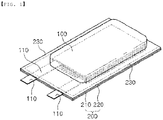
- such a secondary battery is configured to have a structure in which an electrode assembly 100 is mounted in a battery case 200 and in which positive and negative electrode tabs and are welded respectively to two lead members 110, which are exposed out of the battery case 200.
- the battery case 200 configured to receive the electrode assembly 100 has a structure in which a lower case 220 and an upper case 210 covering the lower case 220 are integrally formed, and a surface in which the lower case 220 and the upper case 210 contact each other is bent and folded.
- the lower case 220 and the upper case 210 have a laminate structure consisting of an inner coating layer, a metal layer and an outer coating layer.
- a process of cutting the lower case 220 and the upper case 210 is involved, and in this process, the metal layer is exposed to the outside, which is a cause for significantly reducing the battery performance, such as accelerating the deterioration of the battery.
- Korean Patent Application Publication No. 2016-131706 discloses a method of manufacturing a pouch-type secondary battery including a step of receiving an electrode assembly between an upper sheathing member and a lower sheathing member of a pouch, a step of primary sealing an outer regions of the upper sheathing member and the lower sheathing member of the pouch, a step of cutting edges of the upper sheathing member and the lower sheathing member of the sealed pouch, and a step of pressing distal ends of the upper sheathing member and the lower sheathing member of the cut pouch to form an additional sealing portion on a surface of a cutting portion of the upper sheathing member and the lower sheathing member.
- the present invention has been made in view of the above problems, and it is an object of the present invention to provide a method of manufacturing a pouch-type secondary battery having a simple process and a low defective rate and a pouch-type secondary battery manufactured thereby by forming a coating layer covering a metal layer on a side surface of a sealing portion configured to couple an upper case and a lower case.
- a pouch-type secondary battery including a battery case made of a laminate sheet; and an electrode assembly received in the batter case, wherein the battery case is composed of an upper case and a lower case made of a laminate sheet including an outer coating layer, a metal layer and an inner coating layer; a sealing portion configured to couple the upper case and the lower case to each other is provided at an outer periphery of the upper case and the lower case; and a conformal coating layer configured to prevent exposure of the metal layer is formed at a side surface of the sealing portion.
- a resin coating layer is further formed on a predetermined area of an outer surface of the conformal coating layer, and the resin coating layer may be formed by melting a portion of the outer coating layer.
- a resin coating layer may be further formed on a predetermined region of an inner surface of the conformal coating layer, and the resin coating layer may be formed by melting a portion of the outer coating layer and/or the inner coating layer.
- a method of manufacturing of a pouch-type secondary battery may include a first step of preparing a battery case including an upper case and a lower case by cutting a laminate sheet including an outer coating layer, a metal layer, and an inner coating layer; a second step of receiving an electrode assembly between the upper case and the lower case; a third step of closely contacting a sealing portion provided at an outer periphery of the upper case and the lower case; and a fourth step of forming a conformal coating layer on a side surface of the sealing portion so as to prevent the exposure of the metal layer.
- the method of manufacturing of the pouch-type secondary battery according to the present invention it is preferable to further include a fifth step of sealing the upper case and the lower case by heat sealing the sealing portion of the upper case and the lower case.
- a resin coating layer may be formed on a predetermined area of an outer surface of the conformal coating layer, wherein the resin coating layer is formed of a part of the outer coating layer melted during the heat sealing of the sealing portion.
- a method of manufacturing of a pouch-type secondary battery may include a first step of preparing a battery case including an upper case and a lower case by cutting a laminate sheet comprising an outer coating layer, a metal layer, and an inner coating layer; a second step of receiving an electrode assembly between the upper case and the lower case; a third step of closely contacting a sealing portion provided at an outer periphery of the upper case and the lower case; a fourth step of sealing the upper case and the lower case by heat sealing the sealing portion of the outer periphery of the upper case and the lower case; and a fifth step of forming a conformal coating layer on a side surface of the sealing portion so as to prevent the exposure of the metal layer.
- a resin coating layer may be partially formed on a predetermined area of a side surface of the sealing portion, the resin coating layer being formed of a part of the outer coating layer and/or the inner coating layer melted during the heat sealing of the sealing portion.
- a battery module according to the present invention may be the battery module including the pouch-type secondary battery.
- a battery pack according to the present invention may be the battery pack including the battery module.
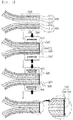
- FIG. 2 is a flowchart illustrating a method of manufacturing a pouch-type secondary battery according to a preferred first embodiment of the present invention
- FIG. 3 is a process diagram illustrating an assembly process of an upper case and a lower case according to the first embodiment.
- the method of manufacturing the pouch-type secondary battery according to the first embodiment of the present invention includes a first step of preparing a battery case 200 including an upper case 210 and a lower case 220; a second step of receiving an electrode assembly 100 between the upper case 210 and the lower case 220; a third step of closely contacting a sealing portion 230 provided at an outer periphery of the upper case 210 and the lower case 220; a fourth step of forming a conformal coating layer 241 on a side surface of the sealing portion 230; and a fifth step of sealing the upper case 210 and the lower case 220 by heat sealing the sealing portion 230 of the outer periphery of the upper case 210 and the lower case 220.
- the battery case 200 is a case accommodating the electrode assembly 100, and forms a space part which can accommodate the electrode assembly 100 using a laminate sheet made of outer coating layers 211 and 221; metal layers 212 and 222; and inner coating layers 213 and 223.
- the inner coating layers 213 and 223 directly contact the electrode assembly 100. For this reason, it is necessary for the inner coating layers to exhibit an insulation property and electrolytic resistance. In addition, for hermetically sealing the inside and the outside of the pouch-type secondary battery, it is necessary for the inner coating layers to exhibit high sealability. Thus, it is necessary for a sealing portion, formed by thermally adhering inner layers of the upper case and the lower case, to exhibit excellent thermal adhesive strength.
- the material for the inner coating layers 213 and 223 may be selected from among a polyolefin-based resin, such as polypropylene, polyethylene, polyethylene acrylate, or polybutylene, a polyurethane resin, and a polyimide resin, which exhibit excellent chemical resistance and good sealability.
- a polyolefin-based resin such as polypropylene, polyethylene, polyethylene acrylate, or polybutylene
- a polyurethane resin such as polyethylene, polyethylene acrylate, or polybutylene
- a polyurethane resin such as polyethylene acrylate, or polybutylene
- a polyurethane resin such as polyurethane resin
- polyimide resin which exhibit excellent chemical resistance and good sealability.
- the present invention is not limited thereto.
- polypropylene which exhibits excellent mechanical properties, such as tensile strength, rigidity, surface hardness, and impact resistance, as well as excellent chemical resistance, is the most preferable.
- the metal layers 212 and 222 which abut the inner coating layers 213 and 223, correspond to a barrier layer configured to prevent the permeation of moisture or various kinds of gases from the outside into the battery.
- An aluminum thin film which is lightweight and exhibits excellent formability, may be used as a preferred material for the metal layer.
- the outer coating layers 211 and 221 are provided at the other surfaces of the metal layers 212 and 222.
- the outer coating layers 211 and 221 may be made of a heat-resistant polymer that exhibits excellent tensile strength, moisture permeation prevention capability, and air permeation prevention capability such that the outer coating layer exhibits heat resistance and chemical resistance while protecting the electrode assembly 100.
- the outer coating layer may be made of nylon or polyethylene terephthalate.
- the present invention is not limited thereto.
- the electrode assembly 100 received in the battery case 200 may be a jelly-roll type electrode assembly, which is configured to have a structure in which a long sheet type positive electrode and a long sheet type negative electrode are wound in the state in which a separator is interposed between the positive electrode and the negative electrode, a stacked type electrode assembly including unit cells, each of which is configured to have a structure in which a rectangular positive electrode and a rectangular negative electrode are stacked in the state in which a separator is interposed between the positive electrode and the negative electrode, a stack/folded type electrode assembly, which is configured to have a structure in which the unit cells are wound in the state in which the unit cells are disposed on a long separation film, or a laminated/stacked type electrode assembly, which is configured to have a structure in which the unit cells are stacked so as to be attached to each other in the state in which a separator is interposed between the unit cells.
- the present invention is not limited thereto.
- a lead member 110 which generally includes a positive electrode lead and a negative electrode lead, is configured to have a structure in which a positive electrode tab (not shown) and a negative electrode tab (not shown), which are attached to the upper end of the electrode assembly 100, are electrically connected to the positive electrode lead and the negative electrode lead, respectively, by welding and in which the lead member 110 is exposed out of the battery case 200.
- a pair of insulative films (not shown), which face each other, is located in the region of the sealing portion 230 at which the positive electrode lead and the negative electrode lead are located, and the lead member 110 is disposed so as to extend between the pair of insulative films (not shown).
- the sealing portion 230 of the upper case 210 and the sealing portion 230 of the lower case 220 are simply brought into close contact with each other, in the state in which the electrode assembly 100 is accommodated. Specifically, using a pair of sealing bars 300 located on the top and bottom of the sealing portion 230 of the upper case 210 and the lower case 220, the sealing portion 230 of the upper case 210 and the lower case 220 is pressed by a predetermined force to be in close contact with each other. At this time, the sealing portion 230 is not heated, and therefore, melting of the inner coating layers 213 and 223 and the outer coating layers 211 and 221 does not occur.
- the pair of sealing bars 300 are preferably further provided with a bent portion 310 bent at a predetermined angle, and a wing portion 320 extending from the bent portion 310.
- one of the sealing bars 300 in contact with the upper surface of the outer coating layer 211 of the upper case 210 includes the bent portion 310, which is bent downward after extending a predetermined length in the direction of a cut surface of the upper case 210, and the wing portion 320 extending upward while being inclined at a predetermined angle from the bent portion 310.
- the other sealing bar 300 in contact with the lower surface of the outer coating layer 221 of the lower case 220 includes the bent portion 310, which is bent upward after extending a predetermined length in the direction of a cut surface of the lower case 220, and the wing portion 320 extending downward while being inclined at a predetermined angle from the bent portion 310.
- the wing portion 320 is provided to protect the sealing bar 300 from the conformal coating resin to be sprayed, and to allow the conformal coating layer 241 to be seated intensively at a desired position.
- the bent portion 310 is provided to induce a part of the resin of the molten outer coating layers 211 and 221 to move to a desired position.
- the fourth step is to form the conformal coating layer 241 near the sealing portion 230, more specifically, on a side surface of the sealing portion 230, which is a cut surface of the laminate sheet.
- the upper case 210 and the lower case 220 constituting the battery case 200 are obtained by cutting and forming the laminate sheet including the outer coating layers 211 and 221; the metal layers 212 and 222; and the inner coating layers 213 and 223. Therefore, even if the sealing portion 230 is heat-sealed, some or all of the metal layers 212 and 222 are generally exposed to the outside, and thus are in an electrically vulnerable state.
- the conformal coating layer 241 is formed so that cut surfaces of the metal layers 212 and 222 are not exposed to the outside.
- the conformal coating layer 241 may be formed on the outer coating layers 211 and 221 and/or the inner coating layers 213 and 223 as well as the metal layers 212 and 222.
- conformal coating is a process of forming a protective film with a predetermined resin on the surface of a PCB assembly generally completed by mounting electronic components on a printed circuit board (PCB).
- the protective film is formed by coating the surface of the PCB assembly with a resin for conformal coating through various coating methods.
- the protective film may be formed through various methods such as a spray coating method for discharging a resin for conformal coating, a flow coating method, a dip coating method for immersing a part of the PCB assembly in a liquid resin solution for conformal coating, or a chemical vapor deposition method.
- a spray coating method is preferred in the present invention because the metal layers 212 and 222 exposed to the outside, or the outer coating layers 211 and 221 and/or the inner coating layers 213 and 223 adjacent to the metal layers 212 and 222 may be selectively coated.
- the resin for conformal coating is not particularly limited as long as it can form a film on the metal layers 212 and 222, and may be subjected to a cooling process for a predetermined time for curing after spray coating.
- the conformal coating layer 240 on the side surface of the sealing portion 230 formed through the above process perfectly coats the metal layers 212 and 222, causes of deteriorating the battery performance such as corrosion and insulation resistance caused by moisture or air coming into contact with the metal layers can be fundamentally blocked.
- the fifth step is performed by heat sealing the sealing portion 230 of the outer periphery of the upper case 210 and the lower case 220 to seal the upper case 210 and the lower case 220.
- the battery case 200 is sealed by heating the sealing portions 230 provided along the periphery of the upper case 210 and the lower case 220 so that the inner coating layers 213 and 223 are bonded to each other.
- a part of the resin of the outer coating layers 211 and 221 is also melted together to form a resin coating layer 242 on a predetermined area of the outer surface of the conformal coating layer 241. Since the resin coating layer 242 extends to the conformal coating layer 241 in the state in which it is connected to the outer coating layers 211 and 221, the resin coating layer 242 may prevent the conformal coating layer 241 from being exfoliated, and may more reliably protect the metal layers 212 and 222 from moisture or air.
- the thickness of the outer coating layers 211 and 221 may be the same as that of the conventional art, and it is possible to apply a conventional heat sealing temperature and time.
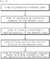
- FIG. 4 is a flowchart illustrating a method of manufacturing a pouch-type secondary battery according to a preferred second embodiment of the present invention
- FIG. 5 is a process diagram illustrating an assembly process of an upper case and a lower case according to the second embodiment.
- the method of manufacturing the pouch-type secondary battery according to the second embodiment of the present invention includes a first step of preparing a battery case 200 including an upper case 210 and a lower case 220; a second step of receiving an electrode assembly 100 between the upper case 210 and the lower case 220; a third step of closely contacting a sealing portion 230 provided at an outer periphery of the upper case 210 and the lower case 220; a fourth step of sealing the upper case 210 and the lower case 220 by heat sealing the sealing portion 230 of the outer periphery of the upper case 210 and the lower case 220; and a fifth step of forming a conformal coating layer 241 on a side surface of the sealing portion 230.
- the configuration of the first step to the third step is identical to the first step to the third step of the first embodiment described above, and therefore a detailed description thereof will be omitted, and the fourth and fifth steps different from the first embodiment will be described.
- the battery case 200 is sealed by heating the sealing portions 230 provided along the periphery of the upper case 210 and the lower case 220 so that the inner coating layers 213 and 223 are bonded to each other.
- a part of the molten resin of the outer coating layers 211 and 221 and/or the inner coating layers 213 and 223 flows to a side surface of the sealing portion 230 to form a resin coating layer 242 on some exposed part of the metal layers 212 and 222.
- the fifth step is a step of forming a conformal coating layer 241 on the side surface of the sealing portion 230 so that the cut surfaces of the metal layers 212 and 222 are not exposed to the outside.
- the metal layers 212 and 222 can be protected from moisture or air since a film is formed on all the metal layers 212 and 222 by the conformal coating layer 241.
- the conformal coating layer 241 has been described in detail in the first embodiment, and therefore a description thereof will be omitted.
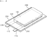
- FIG. 6 is a perspective view showing a pouch-type secondary battery manufactured according to the present invention.
- the pouch-type secondary battery manufactured according to the first or second embodiment of the present invention includes an electrode assembly 100 received in a battery case 200 composed of an upper case 210 and a lower case 220 made of a laminate sheet including outer coating layers 211 and 221, metal layers 212 and 222, and inner coating layers 213 and 223.
- a coating layer 240 for preventing exposure of the metal layer is additionally formed on a side surface of a sealing portion 230 for coupling the upper case 210 and the lower case 220.
- the pouch-type secondary battery manufactured according to the first embodiment is provided with the coating layer 240 formed in a shape in which a resin coating layer 241, formed by melting a part of the outer coating layer 211 and 221, is additionally formed on a predetermined area of the outer surface of a conformal coating layer 242.
- the pouch-type secondary battery manufactured according to the second embodiment is provided with the coating layer 240 formed in a shape in which a resin coating layer 242, formed by melting a part of the outer coating layers 211 and 221 and/or the inner coating layers 213 and 223, is additionally formed on a predetermined area of the inner surface of the conformal coating layer 241.
- the method of manufacturing the pouch-type secondary battery and the pouch-type secondary battery of the present invention since an additional coating layer is formed on a metal layer using a conformal coating method, which has a simple process, it is possible to completely block the metal layer from moisture or air without using a laminate sheet having a thick inner coating layer or an outer coating layer.
Landscapes
- Chemical & Material Sciences (AREA)
- Chemical Kinetics & Catalysis (AREA)
- Electrochemistry (AREA)
- General Chemical & Material Sciences (AREA)
- Engineering & Computer Science (AREA)
- Mechanical Engineering (AREA)
- General Engineering & Computer Science (AREA)
- Inorganic Chemistry (AREA)
- Manufacturing & Machinery (AREA)
- Sealing Battery Cases Or Jackets (AREA)
- Life Sciences & Earth Sciences (AREA)
- Wood Science & Technology (AREA)
Abstract
Description
- This application claims the benefit of priority to Korean Patent Application No.
2018-0163948 filed on December 18, 2018 - The present invention relates to a pouch-type secondary battery and a method of manufacturing the same, and more particularly to a pouch-type secondary battery and a method of manufacturing the same, capable of completely protecting a metal layer from moisture or air by forming an insulating coating layer including a conformal coating layer on the metal layer exposed to a cut surface of a battery case.
- As mobile devices have been continuously developed and the demand for mobile devices has increased, secondary batteries, which are capable of being charged and discharged, have been used as energy sources for various mobile devices. In addition, secondary batteries have also attracted considerable attention as energy sources for electric vehicles and hybrid electric vehicles, which have been presented as alternatives to existing gasoline and diesel vehicles using fossil fuels.
- Based on the shape of a battery case, secondary batteries are classified into a cylindrical battery having an electrode assembly mounted in a cylindrical metal can, a prismatic battery having an electrode assembly mounted in a prismatic metal can, and a pouch-shaped battery having an electrode assembly mounted in a pouch-shaped case made of an aluminum laminate sheet.
- The electrode assembly, which is mounted in the battery case, is a power generating element that is configured to have a structure including a positive electrode, a negative electrode, and a separator that is interposed between the positive electrode and the negative electrode and that can be charged and discharged. The electrode assembly is classified as a jelly-roll type electrode assembly, which is configured to have a structure in which a long sheet type positive electrode and a long sheet type negative electrode, to which active materials are applied, are wound in the state in which a separator is disposed between the positive electrode and the negative electrode, or a stacked type electrode assembly, which is configured to have a structure in which a plurality of positive electrodes having a predetermined size and a plurality of negative electrodes having a predetermined size are sequentially stacked in the state in which separators are disposed respectively between the positive electrodes and the negative electrodes. The jelly-roll type electrode assembly has advantages in that it is easy to manufacture the jelly-roll type electrode assembly and in that the jelly-roll type electrode assembly has high energy density per unit weight.
- As shown in
FIG. 1 , such a secondary battery is configured to have a structure in which anelectrode assembly 100 is mounted in abattery case 200 and in which positive and negative electrode tabs and are welded respectively to twolead members 110, which are exposed out of thebattery case 200. - Meanwhile, the
battery case 200 configured to receive theelectrode assembly 100 has a structure in which alower case 220 and anupper case 210 covering thelower case 220 are integrally formed, and a surface in which thelower case 220 and theupper case 210 contact each other is bent and folded. Thelower case 220 and theupper case 210 have a laminate structure consisting of an inner coating layer, a metal layer and an outer coating layer. In the case of a general pouch-type secondary battery manufacturing method, a process of cutting thelower case 220 and theupper case 210 is involved, and in this process, the metal layer is exposed to the outside, which is a cause for significantly reducing the battery performance, such as accelerating the deterioration of the battery. - As an example of the conventional art for solving the above problem, Korean Patent Application Publication No.
2016-131706 - According to the above-mentioned prior document, there is an advantage that it can prevent the disadvantage in which an exposed portion of a metal layer is in contact with a metal material of a pack unit by forming an additional sealing portion on the surface of the cutting portion of the sheathing member. Since a part of a material of an inner resin layer is leaked to the outside of the cut surface through the pressing to form the additional sealing portion, however, the inner resin layer should be formed thick, and thus there is a problem that the overall volume of the battery case is increased. In addition, there is a problem that a part of an exposed surface of the metal layer is not likely to form a sealing portion because the additional sealing portion is simply formed relying on the pressing.
- Korean Patent Application Publication No.
2016-131706 - The present invention has been made in view of the above problems, and it is an object of the present invention to provide a method of manufacturing a pouch-type secondary battery having a simple process and a low defective rate and a pouch-type secondary battery manufactured thereby by forming a coating layer covering a metal layer on a side surface of a sealing portion configured to couple an upper case and a lower case.
- In accordance with the present invention, the above and other objects can be accomplished by the provision of a pouch-type secondary battery, the pouch-type secondary battery including a battery case made of a laminate sheet; and an electrode assembly received in the batter case, wherein the battery case is composed of an upper case and a lower case made of a laminate sheet including an outer coating layer, a metal layer and an inner coating layer; a sealing portion configured to couple the upper case and the lower case to each other is provided at an outer periphery of the upper case and the lower case; and a conformal coating layer configured to prevent exposure of the metal layer is formed at a side surface of the sealing portion.
- Here, a resin coating layer is further formed on a predetermined area of an outer surface of the conformal coating layer, and the resin coating layer may be formed by melting a portion of the outer coating layer.
- Also, a resin coating layer may be further formed on a predetermined region of an inner surface of the conformal coating layer, and the resin coating layer may be formed by melting a portion of the outer coating layer and/or the inner coating layer.
- Also, a method of manufacturing of a pouch-type secondary battery according to a preferred first embodiment of the present invention may include a first step of preparing a battery case including an upper case and a lower case by cutting a laminate sheet including an outer coating layer, a metal layer, and an inner coating layer; a second step of receiving an electrode assembly between the upper case and the lower case; a third step of closely contacting a sealing portion provided at an outer periphery of the upper case and the lower case; and a fourth step of forming a conformal coating layer on a side surface of the sealing portion so as to prevent the exposure of the metal layer.
- Also, in the method of manufacturing of the pouch-type secondary battery according to the present invention, it is preferable to further include a fifth step of sealing the upper case and the lower case by heat sealing the sealing portion of the upper case and the lower case.
- Also, in the fifth step, a resin coating layer may be formed on a predetermined area of an outer surface of the conformal coating layer, wherein the resin coating layer is formed of a part of the outer coating layer melted during the heat sealing of the sealing portion.
- Also, a method of manufacturing of a pouch-type secondary battery according to a preferred second embodiment of the present invention may include a first step of preparing a battery case including an upper case and a lower case by cutting a laminate sheet comprising an outer coating layer, a metal layer, and an inner coating layer; a second step of receiving an electrode assembly between the upper case and the lower case; a third step of closely contacting a sealing portion provided at an outer periphery of the upper case and the lower case; a fourth step of sealing the upper case and the lower case by heat sealing the sealing portion of the outer periphery of the upper case and the lower case; and a fifth step of forming a conformal coating layer on a side surface of the sealing portion so as to prevent the exposure of the metal layer.
- Also, in the fourth step, a resin coating layer may be partially formed on a predetermined area of a side surface of the sealing portion, the resin coating layer being formed of a part of the outer coating layer and/or the inner coating layer melted during the heat sealing of the sealing portion.
- In addition, a battery module according to the present invention may be the battery module including the pouch-type secondary battery.
- In addition, a battery pack according to the present invention may be the battery pack including the battery module.
-
-
FIG. 1 is a perspective view showing a conventional pouch-type secondary battery. -
FIG. 2 is a flowchart illustrating a method of manufacturing a pouch-type secondary battery according to a preferred first embodiment of the present invention. -
FIG. 3 is a process diagram illustrating an assembly process of an upper case and a lower case according to the first embodiment. -
FIG. 4 is a flowchart illustrating a method of manufacturing a pouch-type secondary battery according to a preferred second embodiment of the present invention. -
FIG. 5 is a process diagram illustrating an assembly process of an upper case and a lower case according to the second embodiment. -
FIG. 6 is a perspective view showing a pouch-type secondary battery manufactured according to the present invention. - In the present application, it should be understood that the terms "comprises," "has," or "includes," etc. specify the presence of features, integers, steps, operations, components, parts, or combinations thereof described in the specification, but do not preclude the presence or addition of one or more other features, integers, steps, operations, components, parts, or combinations thereof.
- In addition, the same reference numbers will be used throughout the drawings to refer to parts that perform similar functions or operations. In the case in which one part is said to be connected to another part in the specification, not only may the one part be directly connected to the another part, but also, the one part may be indirectly connected to the another part via a further part. In addition, that a certain element is included does not mean that other elements are excluded, but means that such elements may be further included unless mentioned otherwise.
- Hereinafter, a pouch-type secondary battery and a method of manufacturing the same according to the present invention will be described with reference to the accompanying drawings.
-
FIG. 2 is a flowchart illustrating a method of manufacturing a pouch-type secondary battery according to a preferred first embodiment of the present invention, andFIG. 3 is a process diagram illustrating an assembly process of an upper case and a lower case according to the first embodiment. - The method of manufacturing the pouch-type secondary battery according to the first embodiment of the present invention includes a first step of preparing a
battery case 200 including anupper case 210 and alower case 220; a second step of receiving anelectrode assembly 100 between theupper case 210 and thelower case 220; a third step of closely contacting asealing portion 230 provided at an outer periphery of theupper case 210 and thelower case 220; a fourth step of forming aconformal coating layer 241 on a side surface of thesealing portion 230; and a fifth step of sealing theupper case 210 and thelower case 220 by heat sealing thesealing portion 230 of the outer periphery of theupper case 210 and thelower case 220. - First, the first step of preparing the
battery case 200 including theupper case 210 and thelower case 220 and the second step of receiving theelectrode assembly 100 between theupper case 210 and thelower case 220 will be described in more detail. Thebattery case 200 is a case accommodating theelectrode assembly 100, and forms a space part which can accommodate theelectrode assembly 100 using a laminate sheet made ofouter coating layers metal layers inner coating layers - The
inner coating layers electrode assembly 100. For this reason, it is necessary for the inner coating layers to exhibit an insulation property and electrolytic resistance. In addition, for hermetically sealing the inside and the outside of the pouch-type secondary battery, it is necessary for the inner coating layers to exhibit high sealability. Thus, it is necessary for a sealing portion, formed by thermally adhering inner layers of the upper case and the lower case, to exhibit excellent thermal adhesive strength. - The material for the
inner coating layers - The
metal layers inner coating layers - The
outer coating layers metal layers outer coating layers electrode assembly 100. In an example, the outer coating layer may be made of nylon or polyethylene terephthalate. However, the present invention is not limited thereto. - The
electrode assembly 100 received in thebattery case 200 may be a jelly-roll type electrode assembly, which is configured to have a structure in which a long sheet type positive electrode and a long sheet type negative electrode are wound in the state in which a separator is interposed between the positive electrode and the negative electrode, a stacked type electrode assembly including unit cells, each of which is configured to have a structure in which a rectangular positive electrode and a rectangular negative electrode are stacked in the state in which a separator is interposed between the positive electrode and the negative electrode, a stack/folded type electrode assembly, which is configured to have a structure in which the unit cells are wound in the state in which the unit cells are disposed on a long separation film, or a laminated/stacked type electrode assembly, which is configured to have a structure in which the unit cells are stacked so as to be attached to each other in the state in which a separator is interposed between the unit cells. However, the present invention is not limited thereto. - A
lead member 110, which generally includes a positive electrode lead and a negative electrode lead, is configured to have a structure in which a positive electrode tab (not shown) and a negative electrode tab (not shown), which are attached to the upper end of theelectrode assembly 100, are electrically connected to the positive electrode lead and the negative electrode lead, respectively, by welding and in which thelead member 110 is exposed out of thebattery case 200. At this time, in order to provide insulativity and sealability, a pair of insulative films (not shown), which face each other, is located in the region of the sealingportion 230 at which the positive electrode lead and the negative electrode lead are located, and thelead member 110 is disposed so as to extend between the pair of insulative films (not shown). - In the third step of closely contacting the sealing
portion 230 provided at the outer periphery of theupper case 210 and thelower case 220, the sealingportion 230 of theupper case 210 and the sealingportion 230 of thelower case 220 are simply brought into close contact with each other, in the state in which theelectrode assembly 100 is accommodated. Specifically, using a pair of sealingbars 300 located on the top and bottom of the sealingportion 230 of theupper case 210 and thelower case 220, the sealingportion 230 of theupper case 210 and thelower case 220 is pressed by a predetermined force to be in close contact with each other. At this time, the sealingportion 230 is not heated, and therefore, melting of the inner coating layers 213 and 223 and the outer coating layers 211 and 221 does not occur. - Here, the pair of sealing
bars 300 are preferably further provided with abent portion 310 bent at a predetermined angle, and awing portion 320 extending from thebent portion 310. - More specifically, one of the sealing bars 300 in contact with the upper surface of the
outer coating layer 211 of theupper case 210 includes thebent portion 310, which is bent downward after extending a predetermined length in the direction of a cut surface of theupper case 210, and thewing portion 320 extending upward while being inclined at a predetermined angle from thebent portion 310. - Also, the other sealing
bar 300 in contact with the lower surface of theouter coating layer 221 of thelower case 220 includes thebent portion 310, which is bent upward after extending a predetermined length in the direction of a cut surface of thelower case 220, and thewing portion 320 extending downward while being inclined at a predetermined angle from thebent portion 310. - When forming the
conformal coating layer 241 performed in the fourth step, thewing portion 320 is provided to protect the sealingbar 300 from the conformal coating resin to be sprayed, and to allow theconformal coating layer 241 to be seated intensively at a desired position. When heating the sealingportion 230 performed in the fifth step, thebent portion 310 is provided to induce a part of the resin of the molten outer coating layers 211 and 221 to move to a desired position. - The fourth step is to form the
conformal coating layer 241 near the sealingportion 230, more specifically, on a side surface of the sealingportion 230, which is a cut surface of the laminate sheet. - The
upper case 210 and thelower case 220 constituting thebattery case 200 are obtained by cutting and forming the laminate sheet including the outer coating layers 211 and 221; the metal layers 212 and 222; and the inner coating layers 213 and 223. Therefore, even if the sealingportion 230 is heat-sealed, some or all of the metal layers 212 and 222 are generally exposed to the outside, and thus are in an electrically vulnerable state. - In the fourth step of the present invention, the
conformal coating layer 241 is formed so that cut surfaces of the metal layers 212 and 222 are not exposed to the outside. - Here, the
conformal coating layer 241 may be formed on the outer coating layers 211 and 221 and/or the inner coating layers 213 and 223 as well as the metal layers 212 and 222. - Meanwhile, conformal coating is a process of forming a protective film with a predetermined resin on the surface of a PCB assembly generally completed by mounting electronic components on a printed circuit board (PCB). In other words, when the PCB assembly is prepared, the protective film is formed by coating the surface of the PCB assembly with a resin for conformal coating through various coating methods. The protective film may be formed through various methods such as a spray coating method for discharging a resin for conformal coating, a flow coating method, a dip coating method for immersing a part of the PCB assembly in a liquid resin solution for conformal coating, or a chemical vapor deposition method.
- Among the above various methods, a spray coating method is preferred in the present invention because the metal layers 212 and 222 exposed to the outside, or the outer coating layers 211 and 221 and/or the inner coating layers 213 and 223 adjacent to the metal layers 212 and 222 may be selectively coated.
- The resin for conformal coating is not particularly limited as long as it can form a film on the metal layers 212 and 222, and may be subjected to a cooling process for a predetermined time for curing after spray coating.
- Since the
conformal coating layer 240 on the side surface of the sealingportion 230 formed through the above process perfectly coats the metal layers 212 and 222, causes of deteriorating the battery performance such as corrosion and insulation resistance caused by moisture or air coming into contact with the metal layers can be fundamentally blocked. - Subsequently, the fifth step is performed by heat sealing the sealing
portion 230 of the outer periphery of theupper case 210 and thelower case 220 to seal theupper case 210 and thelower case 220. - In the fifth step, in order to maintain the sealed state of the pouch-type secondary battery, the
battery case 200 is sealed by heating the sealingportions 230 provided along the periphery of theupper case 210 and thelower case 220 so that the inner coating layers 213 and 223 are bonded to each other. - At this time, a part of the resin of the outer coating layers 211 and 221 is also melted together to form a
resin coating layer 242 on a predetermined area of the outer surface of theconformal coating layer 241. Since theresin coating layer 242 extends to theconformal coating layer 241 in the state in which it is connected to the outer coating layers 211 and 221, theresin coating layer 242 may prevent theconformal coating layer 241 from being exfoliated, and may more reliably protect the metal layers 212 and 222 from moisture or air. - Moreover, since it is not necessary to form a film on all surfaces of the metal layers 212 and 222, in order to manufacture the pouch-type secondary battery having the conformal coating layer, the thickness of the outer coating layers 211 and 221 may be the same as that of the conventional art, and it is possible to apply a conventional heat sealing temperature and time.
- Next, a second embodiment of the present invention will be described.
FIG. 4 is a flowchart illustrating a method of manufacturing a pouch-type secondary battery according to a preferred second embodiment of the present invention, andFIG. 5 is a process diagram illustrating an assembly process of an upper case and a lower case according to the second embodiment. - The method of manufacturing the pouch-type secondary battery according to the second embodiment of the present invention includes a first step of preparing a
battery case 200 including anupper case 210 and alower case 220; a second step of receiving anelectrode assembly 100 between theupper case 210 and thelower case 220; a third step of closely contacting a sealingportion 230 provided at an outer periphery of theupper case 210 and thelower case 220; a fourth step of sealing theupper case 210 and thelower case 220 by heat sealing the sealingportion 230 of the outer periphery of theupper case 210 and thelower case 220; and a fifth step of forming aconformal coating layer 241 on a side surface of the sealingportion 230. - In the method of manufacturing the pouch-type secondary battery according to the second embodiment of the present invention, the configuration of the first step to the third step is identical to the first step to the third step of the first embodiment described above, and therefore a detailed description thereof will be omitted, and the fourth and fifth steps different from the first embodiment will be described.
- In the fourth step of sealing the
upper case 210 and thelower case 220 by heat sealing the sealingportion 230 of the outer periphery of theupper case 210 and thelower case 220, in order to maintain the sealed state of the pouch-type secondary battery, thebattery case 200 is sealed by heating the sealingportions 230 provided along the periphery of theupper case 210 and thelower case 220 so that the inner coating layers 213 and 223 are bonded to each other. - At this time, a part of the molten resin of the outer coating layers 211 and 221 and/or the inner coating layers 213 and 223 flows to a side surface of the sealing
portion 230 to form aresin coating layer 242 on some exposed part of the metal layers 212 and 222. - The fifth step is a step of forming a
conformal coating layer 241 on the side surface of the sealingportion 230 so that the cut surfaces of the metal layers 212 and 222 are not exposed to the outside. - When the fourth step is performed, even if the resin of the outer coating layers 211 and 221 and/or the inner coating layers 213 and 223 does not cover all the exposed surfaces of the metal layers 212 and 222, the metal layers 212 and 222 can be protected from moisture or air since a film is formed on all the metal layers 212 and 222 by the
conformal coating layer 241. - The
conformal coating layer 241 has been described in detail in the first embodiment, and therefore a description thereof will be omitted. -
FIG. 6 is a perspective view showing a pouch-type secondary battery manufactured according to the present invention. Specifically, the pouch-type secondary battery manufactured according to the first or second embodiment of the present invention includes anelectrode assembly 100 received in abattery case 200 composed of anupper case 210 and alower case 220 made of a laminate sheet including outer coating layers 211 and 221,metal layers - In addition, a
coating layer 240 for preventing exposure of the metal layer is additionally formed on a side surface of a sealingportion 230 for coupling theupper case 210 and thelower case 220. - Specifically, as described in
FIG. 3 , the pouch-type secondary battery manufactured according to the first embodiment is provided with thecoating layer 240 formed in a shape in which aresin coating layer 241, formed by melting a part of theouter coating layer conformal coating layer 242. - On the other hand, as described in
FIG. 5 , the pouch-type secondary battery manufactured according to the second embodiment is provided with thecoating layer 240 formed in a shape in which aresin coating layer 242, formed by melting a part of the outer coating layers 211 and 221 and/or the inner coating layers 213 and 223, is additionally formed on a predetermined area of the inner surface of theconformal coating layer 241. - Although the specific details of the present invention have been described in detail, those skilled in the art will appreciate that the detailed description thereof discloses only preferred embodiments of the present invention and thus does not limit the scope of the present invention. Accordingly, those skilled in the art will appreciate that various changes and modifications are possible, without departing from the category and the technical idea of the present invention, and it will be obvious that such changes and modifications fall within the scope of the appended claims.
-
- 100: Electrode assembly
- 110: Lead member
- 200: Battery case
- 210: Upper case
- 211: Outer coating layer 212: Metal layer
- 213: Inner coating layer
- 220: Lower case
- 221: Outer coating layer 222: Metal layer
- 223: Inner coating layer
- 230: Sealing portion
- 240: Coating layer
- 241: Conformal coating layer 242: Resin coating layer
- 300: Sealing bar
- 310: Bent portion
- 320: Wing portion
- According to the method of manufacturing the pouch-type secondary battery and the pouch-type secondary battery of the present invention, since an additional coating layer is formed on a metal layer using a conformal coating method, which has a simple process, it is possible to completely block the metal layer from moisture or air without using a laminate sheet having a thick inner coating layer or an outer coating layer.
Claims (10)
- A pouch-type secondary battery, comprising:a battery case made of a laminate sheet; andan electrode assembly received in the battery case, whereinthe battery case is composed of an upper case and a lower case made of a laminate sheet comprising an outer coating layer, a metal layer and an inner coating layer,a sealing portion configured to couple the upper case and the lower case to each other is provided at an outer periphery of the upper case and the lower case, anda conformal coating layer configured to prevent exposure of the metal layer is formed at a side surface of the sealing portion.
- The pouch-type secondary battery according to claim 1, wherein a resin coating layer is further formed on a predetermined area of an outer surface of the conformal coating layer, the resin coating layer being formed by melting a portion of the outer coating layer.
- The pouch-type secondary battery according to claim 1, wherein a resin coating layer is further formed on a predetermined area of an inner surface of the conformal coating layer, the resin coating layer being formed by melting a portion of the outer coating layer and/or the inner coating layer.
- A method of manufacturing a pouch-type secondary battery, the method comprising:a first step of preparing a battery case including an upper case and a lower case by cutting a laminate sheet comprising an outer coating layer, a metal layer, and an inner coating layer;a second step of receiving an electrode assembly between the upper case and the lower case;a third step of closely contacting a sealing portion provided at an outer periphery of the upper case and the lower case; anda fourth step of forming a conformal coating layer on a side surface of the sealing portion so as to prevent the exposure of the metal layer.
- The method according to claim 4, further comprising a fifth step of sealing the upper case and the lower case by heat sealing the sealing portion of the upper case and the lower case.
- The method according to claim 5, wherein, in the fifth step, a resin coating layer is formed on a predetermined area of an outer surface of the conformal coating layer, the resin coating layer being formed as a part of the outer coating layer melted during the heat sealing of the sealing portion.
- A method of manufacturing a pouch-type secondary battery, the method comprising:a first step of preparing a battery case including an upper case and a lower case by cutting a laminate sheet comprising an outer coating layer, a metal layer, and an inner coating layer;a second step of receiving an electrode assembly between the upper case and the lower case;a third step of closely contacting a sealing portion provided at an outer periphery of the upper case and the lower case;a fourth step of sealing the upper case and the lower case by heat sealing the sealing portion of the outer periphery of the upper case and the lower case; anda fifth step of forming a conformal coating layer on a side surface of the sealing portion so as to prevent the exposure of the metal layer.
- The method according to claim 7, wherein, in the fourth step, a resin coating layer is partially formed on a predetermined area of a side surface of the sealing portion, the resin coating layer being formed of a part of the outer coating layer and/or the inner coating layer melted during the heat sealing of the sealing portion.
- A battery module comprising the pouch-type secondary battery according to any one of claims 1 to 3.
- A battery pack comprising the battery module according to claim 9.
Applications Claiming Priority (2)
| Application Number | Priority Date | Filing Date | Title |
|---|---|---|---|
| KR1020180163948A KR102384007B1 (en) | 2018-12-18 | 2018-12-18 | Pouch Type Secondary Battery And Method For Preparing The Same |
| PCT/KR2019/017354 WO2020130455A1 (en) | 2018-12-18 | 2019-12-10 | Pouch type secondary battery and method for manufacturing same |
Publications (3)
| Publication Number | Publication Date |
|---|---|
| EP3754741A1 true EP3754741A1 (en) | 2020-12-23 |
| EP3754741A4 EP3754741A4 (en) | 2021-06-23 |
| EP3754741B1 EP3754741B1 (en) | 2025-06-11 |
Family
ID=71102885
Family Applications (1)
| Application Number | Title | Priority Date | Filing Date |
|---|---|---|---|
| EP19899199.4A Active EP3754741B1 (en) | 2018-12-18 | 2019-12-10 | Pouch-type secondary battery and method of manufacturing the same |
Country Status (8)
| Country | Link |
|---|---|
| US (1) | US12126035B2 (en) |
| EP (1) | EP3754741B1 (en) |
| JP (1) | JP7048858B2 (en) |
| KR (1) | KR102384007B1 (en) |
| CN (1) | CN111630677B (en) |
| ES (1) | ES3034960T3 (en) |
| HU (1) | HUE072039T2 (en) |
| WO (1) | WO2020130455A1 (en) |
Families Citing this family (6)
| Publication number | Priority date | Publication date | Assignee | Title |
|---|---|---|---|---|
| US12512535B2 (en) | 2021-06-17 | 2025-12-30 | Lg Energy Solution, Ltd. | Battery cell comprising a pouch case comprising an insulating coating layer and battery module including the same |
| KR20230080571A (en) | 2021-11-30 | 2023-06-07 | 주식회사 엘지에너지솔루션 | Sealing tool for pouch type battery |
| KR20230120513A (en) * | 2022-02-09 | 2023-08-17 | 에스케이온 주식회사 | Case for secondary battery, secondary battery, module and device comprising same |
| CN115579558A (en) * | 2022-10-12 | 2023-01-06 | 上海国轩新能源有限公司 | Sealing method of sealing structure, sealing structure and battery |
| JP7794141B2 (en) | 2023-02-06 | 2026-01-06 | トヨタ自動車株式会社 | Laminated battery, battery stack, and method for manufacturing laminated battery |
| JP2025130887A (en) | 2024-02-28 | 2025-09-09 | トヨタ自動車株式会社 | Battery manufacturing method, battery, and laminate film manufacturing method with end insulating member, and laminate film with end insulating member |
Family Cites Families (23)
| Publication number | Priority date | Publication date | Assignee | Title |
|---|---|---|---|---|
| US6632538B1 (en) * | 1998-02-05 | 2003-10-14 | Dai Nippon Printing Co., Ltd. | Sheet for cell and cell device |
| AUPR199400A0 (en) * | 2000-12-09 | 2001-01-11 | Energy Storage Systems Pty Ltd | A connection between a conductive substrate and a laminate |
| US20020127362A1 (en) * | 2001-03-01 | 2002-09-12 | The University Of Chicago | Flexible laminates and housings for batteries |
| JP4760028B2 (en) * | 2005-01-28 | 2011-08-31 | Tdk株式会社 | Electrochemical device and manufacturing method thereof |
| JP2006286471A (en) | 2005-04-01 | 2006-10-19 | Nissan Motor Co Ltd | Battery manufacturing method and battery |
| JP5202815B2 (en) * | 2006-03-29 | 2013-06-05 | 日本電気株式会社 | Film-clad electrical device and electrical device assembly |
| KR100879893B1 (en) * | 2006-07-10 | 2009-01-21 | 주식회사 엘지화학 | Secondary battery with improved safety |
| JP5254332B2 (en) * | 2007-07-19 | 2013-08-07 | エルジー・ケム・リミテッド | Large capacity battery pack |
| KR101002468B1 (en) * | 2008-07-01 | 2010-12-17 | 삼성에스디아이 주식회사 | Pouch Type Lithium Secondary Battery |
| KR101306190B1 (en) * | 2010-12-02 | 2013-09-09 | 주식회사 엘지화학 | Secondary Battery of Improved Insulating Property |
| KR101472178B1 (en) * | 2012-06-12 | 2014-12-12 | 주식회사 엘지화학 | Pouch typed battery having a non-exposure sealing portion |
| KR101501364B1 (en) | 2012-08-07 | 2015-03-12 | 주식회사 엘지화학 | Secondary battery case and method of producing same |
| KR20140032710A (en) * | 2012-09-07 | 2014-03-17 | 주식회사 엘지화학 | Method for preparing pouch-type secondary battery |
| US9735402B2 (en) * | 2013-07-30 | 2017-08-15 | Lg Chem, Ltd. | Battery cell having double sealing structure |
| KR101811473B1 (en) * | 2013-10-31 | 2017-12-21 | 주식회사 엘지화학 | Waterproof layer coated pouch type secondary battery and method for fabricating thereof |
| EP3171424B1 (en) * | 2014-07-16 | 2021-08-25 | Toppan Printing Co., Ltd. | Casing material for electricity storage device and electricity storage device including same |
| JP6487669B2 (en) * | 2014-11-05 | 2019-03-20 | 昭和電工パッケージング株式会社 | Power storage device |
| KR101797694B1 (en) | 2015-02-24 | 2017-11-15 | 주식회사 엘지화학 | Battery Pack Having Small PCM |
| KR101805539B1 (en) * | 2015-03-26 | 2017-12-07 | 주식회사 엘지화학 | Method for Coating Edge of Pouch-Type Battery Case and Battery Cell Manufactured from the Same |
| KR101883536B1 (en) * | 2015-04-29 | 2018-07-30 | 주식회사 엘지화학 | Pouch type secondary battery and method of fabricating the same |
| KR20160131706A (en) | 2015-05-08 | 2016-11-16 | 주식회사 엘지화학 | Pouch type secondary battery and method for preparing the same |
| KR102006203B1 (en) | 2015-06-29 | 2019-08-01 | 주식회사 엘지화학 | A pouch case with enhanced insulating property and a pouch type secondary battery |
| KR101883040B1 (en) | 2016-01-08 | 2018-07-27 | 삼성전기주식회사 | Chip resistor |
-
2018
- 2018-12-18 KR KR1020180163948A patent/KR102384007B1/en active Active
-
2019
- 2019-12-10 WO PCT/KR2019/017354 patent/WO2020130455A1/en not_active Ceased
- 2019-12-10 EP EP19899199.4A patent/EP3754741B1/en active Active
- 2019-12-10 US US16/976,982 patent/US12126035B2/en active Active
- 2019-12-10 JP JP2020532996A patent/JP7048858B2/en active Active
- 2019-12-10 HU HUE19899199A patent/HUE072039T2/en unknown
- 2019-12-10 CN CN201980009129.XA patent/CN111630677B/en active Active
- 2019-12-10 ES ES19899199T patent/ES3034960T3/en active Active
Also Published As
| Publication number | Publication date |
|---|---|
| KR102384007B1 (en) | 2022-04-07 |
| CN111630677A (en) | 2020-09-04 |
| EP3754741B1 (en) | 2025-06-11 |
| US12126035B2 (en) | 2024-10-22 |
| ES3034960T3 (en) | 2025-08-27 |
| JP7048858B2 (en) | 2022-04-06 |
| US20210028417A1 (en) | 2021-01-28 |
| HUE072039T2 (en) | 2025-10-28 |
| EP3754741A4 (en) | 2021-06-23 |
| WO2020130455A1 (en) | 2020-06-25 |
| JP2021510901A (en) | 2021-04-30 |
| KR20200075362A (en) | 2020-06-26 |
| CN111630677B (en) | 2022-11-11 |
Similar Documents
| Publication | Publication Date | Title |
|---|---|---|
| EP3754741B1 (en) | Pouch-type secondary battery and method of manufacturing the same | |
| US10141553B2 (en) | Secondary battery and battery module having the same | |
| EP4195379A1 (en) | Battery cell, manufacturing method therefor, and battery module comprising same | |
| EP3671886B1 (en) | Pouch-type secondary battery and pouch for secondary battery | |
| JP4609432B2 (en) | Lead terminal for power storage device with fuse and non-aqueous electrolyte power storage device | |
| EP3537506B1 (en) | Rechargeable battery | |
| US11289782B2 (en) | Secondary battery | |
| KR102085342B1 (en) | An electrode lead for a secondary battery, a pouch type secondary battery and a battery module comprising the same | |
| KR101472178B1 (en) | Pouch typed battery having a non-exposure sealing portion | |
| KR100973314B1 (en) | Protective circuit assembly and battery pack having same | |
| CN110679012B (en) | Secondary battery | |
| US20200044225A1 (en) | Secondary battery | |
| CN1753204B (en) | Composite material tape for lithium secondary battery and lithium secondary battery using the same | |
| JP2024506457A (en) | Pouch-type battery cells with improved safety and battery modules containing the same | |
| US12609427B2 (en) | Secondary battery | |
| CN115885417A (en) | Secondary battery | |
| US20250226489A1 (en) | Pouch-Shaped Battery Cell and Battery Module Including the Same | |
| US20240339737A1 (en) | Pouch-Shaped Battery Cell With Improved Thermal Safety | |
| KR102053987B1 (en) | Battery Cell | |
| US20240304902A1 (en) | Pouch-Type Secondary Battery and Manufacturing Method Therefor | |
| US20250030133A1 (en) | Lead for nonaqueous electrolyte battery | |
| US20250149724A1 (en) | Rechargeable battery | |
| CN116686162A (en) | Pouch type secondary battery and manufacturing method thereof | |
| JP2023544494A (en) | Pouch type battery cell with safety element between electrode lead and lead film |
Legal Events
| Date | Code | Title | Description |
|---|---|---|---|
| STAA | Information on the status of an ep patent application or granted ep patent |
Free format text: STATUS: THE INTERNATIONAL PUBLICATION HAS BEEN MADE |
|
| PUAI | Public reference made under article 153(3) epc to a published international application that has entered the european phase |
Free format text: ORIGINAL CODE: 0009012 |
|
| STAA | Information on the status of an ep patent application or granted ep patent |
Free format text: STATUS: REQUEST FOR EXAMINATION WAS MADE |
|
| 17P | Request for examination filed |
Effective date: 20200918 |
|
| AK | Designated contracting states |
Kind code of ref document: A1 Designated state(s): AL AT BE BG CH CY CZ DE DK EE ES FI FR GB GR HR HU IE IS IT LI LT LU LV MC MK MT NL NO PL PT RO RS SE SI SK SM TR |
|
| AX | Request for extension of the european patent |
Extension state: BA ME |
|
| A4 | Supplementary search report drawn up and despatched |
Effective date: 20210520 |
|
| RIC1 | Information provided on ipc code assigned before grant |
Ipc: H01M 50/10 20210101AFI20210514BHEP Ipc: B05D 7/14 20060101ALI20210514BHEP Ipc: B05D 7/00 20060101ALI20210514BHEP Ipc: B29C 65/02 20060101ALI20210514BHEP Ipc: F16J 15/02 20060101ALI20210514BHEP |
|
| RAP1 | Party data changed (applicant data changed or rights of an application transferred) |
Owner name: LG ENERGY SOLUTION LTD. |
|
| DAV | Request for validation of the european patent (deleted) | ||
| DAX | Request for extension of the european patent (deleted) | ||
| RAP3 | Party data changed (applicant data changed or rights of an application transferred) |
Owner name: LG ENERGY SOLUTION, LTD. |
|
| REG | Reference to a national code |
Ref country code: DE Ref legal event code: R079 Ipc: B05D0001020000 Ref country code: DE Ref legal event code: R079 Ref document number: 602019071134 Country of ref document: DE Free format text: PREVIOUS MAIN CLASS: H01M0002020000 Ipc: B05D0001020000 |
|
| GRAP | Despatch of communication of intention to grant a patent |
Free format text: ORIGINAL CODE: EPIDOSNIGR1 |
|
| STAA | Information on the status of an ep patent application or granted ep patent |
Free format text: STATUS: GRANT OF PATENT IS INTENDED |
|
| RIC1 | Information provided on ipc code assigned before grant |
Ipc: B29C 65/02 20060101ALI20250224BHEP Ipc: H01M 50/193 20210101ALI20250224BHEP Ipc: H01M 50/186 20210101ALI20250224BHEP Ipc: H01M 50/129 20210101ALI20250224BHEP Ipc: H01M 50/121 20210101ALI20250224BHEP Ipc: H01M 50/119 20210101ALI20250224BHEP Ipc: H01M 50/105 20210101ALI20250224BHEP Ipc: F16J 15/12 20060101ALI20250224BHEP Ipc: B29L 31/00 20060101ALI20250224BHEP Ipc: B29C 65/00 20060101ALI20250224BHEP Ipc: B05D 1/02 20060101AFI20250224BHEP |
|
| INTG | Intention to grant announced |
Effective date: 20250310 |
|
| GRAS | Grant fee paid |
Free format text: ORIGINAL CODE: EPIDOSNIGR3 |
|
| GRAA | (expected) grant |
Free format text: ORIGINAL CODE: 0009210 |
|
| STAA | Information on the status of an ep patent application or granted ep patent |
Free format text: STATUS: THE PATENT HAS BEEN GRANTED |
|
| P01 | Opt-out of the competence of the unified patent court (upc) registered |
Free format text: CASE NUMBER: APP_16828/2025 Effective date: 20250407 |
|
| AK | Designated contracting states |
Kind code of ref document: B1 Designated state(s): AL AT BE BG CH CY CZ DE DK EE ES FI FR GB GR HR HU IE IS IT LI LT LU LV MC MK MT NL NO PL PT RO RS SE SI SK SM TR |
|
| REG | Reference to a national code |
Ref country code: GB Ref legal event code: FG4D |
|
| REG | Reference to a national code |
Ref country code: CH Ref legal event code: EP |
|
| REG | Reference to a national code |
Ref country code: IE Ref legal event code: FG4D |
|
| REG | Reference to a national code |
Ref country code: DE Ref legal event code: R096 Ref document number: 602019071134 Country of ref document: DE |
|
| REG | Reference to a national code |
Ref country code: ES Ref legal event code: FG2A Ref document number: 3034960 Country of ref document: ES Kind code of ref document: T3 Effective date: 20250827 |
|
| PG25 | Lapsed in a contracting state [announced via postgrant information from national office to epo] |
Ref country code: FI Free format text: LAPSE BECAUSE OF FAILURE TO SUBMIT A TRANSLATION OF THE DESCRIPTION OR TO PAY THE FEE WITHIN THE PRESCRIBED TIME-LIMIT Effective date: 20250611 |
|
| REG | Reference to a national code |
Ref country code: LT Ref legal event code: MG9D |
|
| PG25 | Lapsed in a contracting state [announced via postgrant information from national office to epo] |
Ref country code: NO Free format text: LAPSE BECAUSE OF FAILURE TO SUBMIT A TRANSLATION OF THE DESCRIPTION OR TO PAY THE FEE WITHIN THE PRESCRIBED TIME-LIMIT Effective date: 20250911 Ref country code: GR Free format text: LAPSE BECAUSE OF FAILURE TO SUBMIT A TRANSLATION OF THE DESCRIPTION OR TO PAY THE FEE WITHIN THE PRESCRIBED TIME-LIMIT Effective date: 20250912 |
|
| REG | Reference to a national code |
Ref country code: NL Ref legal event code: MP Effective date: 20250611 |
|
| PG25 | Lapsed in a contracting state [announced via postgrant information from national office to epo] |
Ref country code: BG Free format text: LAPSE BECAUSE OF FAILURE TO SUBMIT A TRANSLATION OF THE DESCRIPTION OR TO PAY THE FEE WITHIN THE PRESCRIBED TIME-LIMIT Effective date: 20250611 |
|
| PG25 | Lapsed in a contracting state [announced via postgrant information from national office to epo] |
Ref country code: HR Free format text: LAPSE BECAUSE OF FAILURE TO SUBMIT A TRANSLATION OF THE DESCRIPTION OR TO PAY THE FEE WITHIN THE PRESCRIBED TIME-LIMIT Effective date: 20250611 |
|
| PG25 | Lapsed in a contracting state [announced via postgrant information from national office to epo] |
Ref country code: RS Free format text: LAPSE BECAUSE OF FAILURE TO SUBMIT A TRANSLATION OF THE DESCRIPTION OR TO PAY THE FEE WITHIN THE PRESCRIBED TIME-LIMIT Effective date: 20250911 |
|
| REG | Reference to a national code |
Ref country code: HU Ref legal event code: AG4A Ref document number: E072039 Country of ref document: HU |
|
| PG25 | Lapsed in a contracting state [announced via postgrant information from national office to epo] |
Ref country code: LV Free format text: LAPSE BECAUSE OF FAILURE TO SUBMIT A TRANSLATION OF THE DESCRIPTION OR TO PAY THE FEE WITHIN THE PRESCRIBED TIME-LIMIT Effective date: 20250611 |
|
| PG25 | Lapsed in a contracting state [announced via postgrant information from national office to epo] |
Ref country code: NL Free format text: LAPSE BECAUSE OF FAILURE TO SUBMIT A TRANSLATION OF THE DESCRIPTION OR TO PAY THE FEE WITHIN THE PRESCRIBED TIME-LIMIT Effective date: 20250611 |
|
| PG25 | Lapsed in a contracting state [announced via postgrant information from national office to epo] |
Ref country code: PT Free format text: LAPSE BECAUSE OF FAILURE TO SUBMIT A TRANSLATION OF THE DESCRIPTION OR TO PAY THE FEE WITHIN THE PRESCRIBED TIME-LIMIT Effective date: 20251013 |
|
| REG | Reference to a national code |
Ref country code: AT Ref legal event code: MK05 Ref document number: 1801968 Country of ref document: AT Kind code of ref document: T Effective date: 20250611 |
|
| PG25 | Lapsed in a contracting state [announced via postgrant information from national office to epo] |
Ref country code: IS Free format text: LAPSE BECAUSE OF FAILURE TO SUBMIT A TRANSLATION OF THE DESCRIPTION OR TO PAY THE FEE WITHIN THE PRESCRIBED TIME-LIMIT Effective date: 20251011 |
|
| PGFP | Annual fee paid to national office [announced via postgrant information from national office to epo] |
Ref country code: DE Payment date: 20251120 Year of fee payment: 7 |
|
| PGFP | Annual fee paid to national office [announced via postgrant information from national office to epo] |
Ref country code: GB Payment date: 20251120 Year of fee payment: 7 |
|
| PG25 | Lapsed in a contracting state [announced via postgrant information from national office to epo] |
Ref country code: AT Free format text: LAPSE BECAUSE OF FAILURE TO SUBMIT A TRANSLATION OF THE DESCRIPTION OR TO PAY THE FEE WITHIN THE PRESCRIBED TIME-LIMIT Effective date: 20250611 Ref country code: SM Free format text: LAPSE BECAUSE OF FAILURE TO SUBMIT A TRANSLATION OF THE DESCRIPTION OR TO PAY THE FEE WITHIN THE PRESCRIBED TIME-LIMIT Effective date: 20250611 |
|
| PGFP | Annual fee paid to national office [announced via postgrant information from national office to epo] |
Ref country code: HU Payment date: 20251216 Year of fee payment: 7 Ref country code: FR Payment date: 20251125 Year of fee payment: 7 |
|
| PGFP | Annual fee paid to national office [announced via postgrant information from national office to epo] |
Ref country code: BE Payment date: 20251120 Year of fee payment: 7 |
|
| PG25 | Lapsed in a contracting state [announced via postgrant information from national office to epo] |
Ref country code: CZ Free format text: LAPSE BECAUSE OF FAILURE TO SUBMIT A TRANSLATION OF THE DESCRIPTION OR TO PAY THE FEE WITHIN THE PRESCRIBED TIME-LIMIT Effective date: 20250611 |
|
| PG25 | Lapsed in a contracting state [announced via postgrant information from national office to epo] |
Ref country code: PL Free format text: LAPSE BECAUSE OF FAILURE TO SUBMIT A TRANSLATION OF THE DESCRIPTION OR TO PAY THE FEE WITHIN THE PRESCRIBED TIME-LIMIT Effective date: 20250611 |
|
| PG25 | Lapsed in a contracting state [announced via postgrant information from national office to epo] |
Ref country code: EE Free format text: LAPSE BECAUSE OF FAILURE TO SUBMIT A TRANSLATION OF THE DESCRIPTION OR TO PAY THE FEE WITHIN THE PRESCRIBED TIME-LIMIT Effective date: 20250611 |
|
| PG25 | Lapsed in a contracting state [announced via postgrant information from national office to epo] |
Ref country code: RO Free format text: LAPSE BECAUSE OF FAILURE TO SUBMIT A TRANSLATION OF THE DESCRIPTION OR TO PAY THE FEE WITHIN THE PRESCRIBED TIME-LIMIT Effective date: 20250611 Ref country code: SK Free format text: LAPSE BECAUSE OF FAILURE TO SUBMIT A TRANSLATION OF THE DESCRIPTION OR TO PAY THE FEE WITHIN THE PRESCRIBED TIME-LIMIT Effective date: 20250611 |
|
| REG | Reference to a national code |
Ref country code: DE Ref legal event code: R097 Ref document number: 602019071134 Country of ref document: DE |
|
| PGFP | Annual fee paid to national office [announced via postgrant information from national office to epo] |
Ref country code: ES Payment date: 20260122 Year of fee payment: 7 |
|
| PG25 | Lapsed in a contracting state [announced via postgrant information from national office to epo] |
Ref country code: DK Free format text: LAPSE BECAUSE OF FAILURE TO SUBMIT A TRANSLATION OF THE DESCRIPTION OR TO PAY THE FEE WITHIN THE PRESCRIBED TIME-LIMIT Effective date: 20250611 |
|
| PG25 | Lapsed in a contracting state [announced via postgrant information from national office to epo] |
Ref country code: IT Free format text: LAPSE BECAUSE OF FAILURE TO SUBMIT A TRANSLATION OF THE DESCRIPTION OR TO PAY THE FEE WITHIN THE PRESCRIBED TIME-LIMIT Effective date: 20250611 |
|
| PLBE | No opposition filed within time limit |
Free format text: ORIGINAL CODE: 0009261 |
|
| STAA | Information on the status of an ep patent application or granted ep patent |
Free format text: STATUS: NO OPPOSITION FILED WITHIN TIME LIMIT |
|
| REG | Reference to a national code |
Ref country code: CH Ref legal event code: L10 Free format text: ST27 STATUS EVENT CODE: U-0-0-L10-L00 (AS PROVIDED BY THE NATIONAL OFFICE) Effective date: 20260423 |