EP3671886B1 - Pouch-type secondary battery and pouch for secondary battery - Google Patents
Pouch-type secondary battery and pouch for secondary battery Download PDFInfo
- Publication number
- EP3671886B1 EP3671886B1 EP19854713.5A EP19854713A EP3671886B1 EP 3671886 B1 EP3671886 B1 EP 3671886B1 EP 19854713 A EP19854713 A EP 19854713A EP 3671886 B1 EP3671886 B1 EP 3671886B1
- Authority
- EP
- European Patent Office
- Prior art keywords
- layer
- pouch
- negative electrode
- metal foil
- secondary battery
- Prior art date
- Legal status (The legal status is an assumption and is not a legal conclusion. Google has not performed a legal analysis and makes no representation as to the accuracy of the status listed.)
- Active
Links
- 229910052751 metal Inorganic materials 0.000 claims description 115
- 239000002184 metal Substances 0.000 claims description 115
- 239000011888 foil Substances 0.000 claims description 80
- 230000004888 barrier function Effects 0.000 claims description 55
- 239000000565 sealant Substances 0.000 claims description 40
- -1 polyethylene terephthalate Polymers 0.000 claims description 21
- 229920000642 polymer Polymers 0.000 claims description 20
- 238000009413 insulation Methods 0.000 claims description 18
- 239000004743 Polypropylene Substances 0.000 claims description 13
- 229920001155 polypropylene Polymers 0.000 claims description 13
- 229910052782 aluminium Inorganic materials 0.000 claims description 12
- XAGFODPZIPBFFR-UHFFFAOYSA-N aluminium Chemical compound [Al] XAGFODPZIPBFFR-UHFFFAOYSA-N 0.000 claims description 11
- 239000010949 copper Substances 0.000 claims description 11
- RYGMFSIKBFXOCR-UHFFFAOYSA-N Copper Chemical compound [Cu] RYGMFSIKBFXOCR-UHFFFAOYSA-N 0.000 claims description 9
- 229910052802 copper Inorganic materials 0.000 claims description 9
- 229920000139 polyethylene terephthalate Polymers 0.000 claims description 9
- 239000005020 polyethylene terephthalate Substances 0.000 claims description 9
- 239000010410 layer Substances 0.000 description 197
- 239000007789 gas Substances 0.000 description 48
- 239000000463 material Substances 0.000 description 24
- 238000007789 sealing Methods 0.000 description 12
- 238000004880 explosion Methods 0.000 description 11
- 239000007774 positive electrode material Substances 0.000 description 9
- 239000003792 electrolyte Substances 0.000 description 8
- 238000004519 manufacturing process Methods 0.000 description 8
- PXHVJJICTQNCMI-UHFFFAOYSA-N Nickel Chemical compound [Ni] PXHVJJICTQNCMI-UHFFFAOYSA-N 0.000 description 7
- 230000004308 accommodation Effects 0.000 description 7
- 239000007773 negative electrode material Substances 0.000 description 7
- 239000002002 slurry Substances 0.000 description 6
- 230000020169 heat generation Effects 0.000 description 5
- 238000003466 welding Methods 0.000 description 5
- 239000004698 Polyethylene Substances 0.000 description 4
- 238000013459 approach Methods 0.000 description 4
- 230000008901 benefit Effects 0.000 description 4
- 230000000694 effects Effects 0.000 description 4
- 229920000573 polyethylene Polymers 0.000 description 4
- 239000004677 Nylon Substances 0.000 description 3
- 239000011248 coating agent Substances 0.000 description 3
- 238000000576 coating method Methods 0.000 description 3
- 238000005260 corrosion Methods 0.000 description 3
- 230000007797 corrosion Effects 0.000 description 3
- XEEYBQQBJWHFJM-UHFFFAOYSA-N iron Substances [Fe] XEEYBQQBJWHFJM-UHFFFAOYSA-N 0.000 description 3
- 229910052759 nickel Inorganic materials 0.000 description 3
- 229920001778 nylon Polymers 0.000 description 3
- 150000003839 salts Chemical class 0.000 description 3
- HBBGRARXTFLTSG-UHFFFAOYSA-N Lithium ion Chemical compound [Li+] HBBGRARXTFLTSG-UHFFFAOYSA-N 0.000 description 2
- 239000004952 Polyamide Substances 0.000 description 2
- 239000004642 Polyimide Substances 0.000 description 2
- 239000004809 Teflon Substances 0.000 description 2
- 229920006362 Teflon® Polymers 0.000 description 2
- 238000005299 abrasion Methods 0.000 description 2
- 239000002253 acid Substances 0.000 description 2
- 239000004760 aramid Substances 0.000 description 2
- 229920003235 aromatic polyamide Polymers 0.000 description 2
- 229920002678 cellulose Polymers 0.000 description 2
- 239000001913 cellulose Substances 0.000 description 2
- 239000002131 composite material Substances 0.000 description 2
- 239000007772 electrode material Substances 0.000 description 2
- 239000003365 glass fiber Substances 0.000 description 2
- 229910052742 iron Inorganic materials 0.000 description 2
- 229910001416 lithium ion Inorganic materials 0.000 description 2
- 238000000034 method Methods 0.000 description 2
- 239000000615 nonconductor Substances 0.000 description 2
- 230000035515 penetration Effects 0.000 description 2
- 229920000058 polyacrylate Polymers 0.000 description 2
- 229920002239 polyacrylonitrile Polymers 0.000 description 2
- 229920002647 polyamide Polymers 0.000 description 2
- 229920001230 polyarylate Polymers 0.000 description 2
- 239000004417 polycarbonate Substances 0.000 description 2
- 229920000515 polycarbonate Polymers 0.000 description 2
- 229920000728 polyester Polymers 0.000 description 2
- 229920001721 polyimide Polymers 0.000 description 2
- 229920000915 polyvinyl chloride Polymers 0.000 description 2
- 239000004800 polyvinyl chloride Substances 0.000 description 2
- 239000002356 single layer Substances 0.000 description 2
- 238000003860 storage Methods 0.000 description 2
- XLYOFNOQVPJJNP-UHFFFAOYSA-N water Substances O XLYOFNOQVPJJNP-UHFFFAOYSA-N 0.000 description 2
- QVGXLLKOCUKJST-UHFFFAOYSA-N atomic oxygen Chemical compound [O] QVGXLLKOCUKJST-UHFFFAOYSA-N 0.000 description 1
- 230000015572 biosynthetic process Effects 0.000 description 1
- 229910052799 carbon Inorganic materials 0.000 description 1
- 229910052804 chromium Inorganic materials 0.000 description 1
- 230000000295 complement effect Effects 0.000 description 1
- 230000006835 compression Effects 0.000 description 1
- 238000007906 compression Methods 0.000 description 1
- 238000005520 cutting process Methods 0.000 description 1
- 230000006866 deterioration Effects 0.000 description 1
- 230000005611 electricity Effects 0.000 description 1
- 229920005570 flexible polymer Polymers 0.000 description 1
- 230000017525 heat dissipation Effects 0.000 description 1
- 239000001257 hydrogen Substances 0.000 description 1
- 229910052739 hydrogen Inorganic materials 0.000 description 1
- 238000003475 lamination Methods 0.000 description 1
- FPYJFEHAWHCUMM-UHFFFAOYSA-N maleic anhydride Chemical compound O=C1OC(=O)C=C1 FPYJFEHAWHCUMM-UHFFFAOYSA-N 0.000 description 1
- 229910052748 manganese Inorganic materials 0.000 description 1
- 239000007769 metal material Substances 0.000 description 1
- 150000002739 metals Chemical class 0.000 description 1
- 239000000203 mixture Substances 0.000 description 1
- 238000012986 modification Methods 0.000 description 1
- 230000004048 modification Effects 0.000 description 1
- 239000001301 oxygen Substances 0.000 description 1
- 229910052760 oxygen Inorganic materials 0.000 description 1
- 229920003023 plastic Polymers 0.000 description 1
- 239000004033 plastic Substances 0.000 description 1
- 229920001690 polydopamine Polymers 0.000 description 1
- 239000002861 polymer material Substances 0.000 description 1
- 229920005672 polyolefin resin Polymers 0.000 description 1
- 229920005989 resin Polymers 0.000 description 1
- 239000011347 resin Substances 0.000 description 1
- 238000005096 rolling process Methods 0.000 description 1
- 238000011076 safety test Methods 0.000 description 1
- 239000000126 substance Substances 0.000 description 1
- 229920001897 terpolymer Polymers 0.000 description 1
Images


Classifications
-
- H—ELECTRICITY
- H01—ELECTRIC ELEMENTS
- H01M—PROCESSES OR MEANS, e.g. BATTERIES, FOR THE DIRECT CONVERSION OF CHEMICAL ENERGY INTO ELECTRICAL ENERGY
- H01M50/00—Constructional details or processes of manufacture of the non-active parts of electrochemical cells other than fuel cells, e.g. hybrid cells
- H01M50/10—Primary casings; Jackets or wrappings
- H01M50/102—Primary casings; Jackets or wrappings characterised by their shape or physical structure
- H01M50/105—Pouches or flexible bags
-
- H—ELECTRICITY
- H01—ELECTRIC ELEMENTS
- H01M—PROCESSES OR MEANS, e.g. BATTERIES, FOR THE DIRECT CONVERSION OF CHEMICAL ENERGY INTO ELECTRICAL ENERGY
- H01M50/00—Constructional details or processes of manufacture of the non-active parts of electrochemical cells other than fuel cells, e.g. hybrid cells
- H01M50/10—Primary casings; Jackets or wrappings
- H01M50/116—Primary casings; Jackets or wrappings characterised by the material
- H01M50/124—Primary casings; Jackets or wrappings characterised by the material having a layered structure
- H01M50/126—Primary casings; Jackets or wrappings characterised by the material having a layered structure comprising three or more layers
- H01M50/129—Primary casings; Jackets or wrappings characterised by the material having a layered structure comprising three or more layers with two or more layers of only organic material
-
- B—PERFORMING OPERATIONS; TRANSPORTING
- B32—LAYERED PRODUCTS
- B32B—LAYERED PRODUCTS, i.e. PRODUCTS BUILT-UP OF STRATA OF FLAT OR NON-FLAT, e.g. CELLULAR OR HONEYCOMB, FORM
- B32B15/00—Layered products comprising a layer of metal
- B32B15/04—Layered products comprising a layer of metal comprising metal as the main or only constituent of a layer, which is next to another layer of the same or of a different material
- B32B15/08—Layered products comprising a layer of metal comprising metal as the main or only constituent of a layer, which is next to another layer of the same or of a different material of synthetic resin
- B32B15/09—Layered products comprising a layer of metal comprising metal as the main or only constituent of a layer, which is next to another layer of the same or of a different material of synthetic resin comprising polyesters
-
- B—PERFORMING OPERATIONS; TRANSPORTING
- B32—LAYERED PRODUCTS
- B32B—LAYERED PRODUCTS, i.e. PRODUCTS BUILT-UP OF STRATA OF FLAT OR NON-FLAT, e.g. CELLULAR OR HONEYCOMB, FORM
- B32B15/00—Layered products comprising a layer of metal
- B32B15/20—Layered products comprising a layer of metal comprising aluminium or copper
-
- H—ELECTRICITY
- H01—ELECTRIC ELEMENTS
- H01M—PROCESSES OR MEANS, e.g. BATTERIES, FOR THE DIRECT CONVERSION OF CHEMICAL ENERGY INTO ELECTRICAL ENERGY
- H01M50/00—Constructional details or processes of manufacture of the non-active parts of electrochemical cells other than fuel cells, e.g. hybrid cells
- H01M50/10—Primary casings; Jackets or wrappings
- H01M50/116—Primary casings; Jackets or wrappings characterised by the material
- H01M50/117—Inorganic material
- H01M50/119—Metals
-
- H—ELECTRICITY
- H01—ELECTRIC ELEMENTS
- H01M—PROCESSES OR MEANS, e.g. BATTERIES, FOR THE DIRECT CONVERSION OF CHEMICAL ENERGY INTO ELECTRICAL ENERGY
- H01M50/00—Constructional details or processes of manufacture of the non-active parts of electrochemical cells other than fuel cells, e.g. hybrid cells
- H01M50/10—Primary casings; Jackets or wrappings
- H01M50/116—Primary casings; Jackets or wrappings characterised by the material
- H01M50/121—Organic material
-
- H—ELECTRICITY
- H01—ELECTRIC ELEMENTS
- H01M—PROCESSES OR MEANS, e.g. BATTERIES, FOR THE DIRECT CONVERSION OF CHEMICAL ENERGY INTO ELECTRICAL ENERGY
- H01M50/00—Constructional details or processes of manufacture of the non-active parts of electrochemical cells other than fuel cells, e.g. hybrid cells
- H01M50/10—Primary casings; Jackets or wrappings
- H01M50/116—Primary casings; Jackets or wrappings characterised by the material
- H01M50/124—Primary casings; Jackets or wrappings characterised by the material having a layered structure
- H01M50/1243—Primary casings; Jackets or wrappings characterised by the material having a layered structure characterised by the internal coating on the casing
-
- H—ELECTRICITY
- H01—ELECTRIC ELEMENTS
- H01M—PROCESSES OR MEANS, e.g. BATTERIES, FOR THE DIRECT CONVERSION OF CHEMICAL ENERGY INTO ELECTRICAL ENERGY
- H01M50/00—Constructional details or processes of manufacture of the non-active parts of electrochemical cells other than fuel cells, e.g. hybrid cells
- H01M50/10—Primary casings; Jackets or wrappings
- H01M50/116—Primary casings; Jackets or wrappings characterised by the material
- H01M50/124—Primary casings; Jackets or wrappings characterised by the material having a layered structure
- H01M50/1245—Primary casings; Jackets or wrappings characterised by the material having a layered structure characterised by the external coating on the casing
-
- H—ELECTRICITY
- H01—ELECTRIC ELEMENTS
- H01M—PROCESSES OR MEANS, e.g. BATTERIES, FOR THE DIRECT CONVERSION OF CHEMICAL ENERGY INTO ELECTRICAL ENERGY
- H01M50/00—Constructional details or processes of manufacture of the non-active parts of electrochemical cells other than fuel cells, e.g. hybrid cells
- H01M50/10—Primary casings; Jackets or wrappings
- H01M50/116—Primary casings; Jackets or wrappings characterised by the material
- H01M50/124—Primary casings; Jackets or wrappings characterised by the material having a layered structure
- H01M50/126—Primary casings; Jackets or wrappings characterised by the material having a layered structure comprising three or more layers
- H01M50/128—Primary casings; Jackets or wrappings characterised by the material having a layered structure comprising three or more layers with two or more layers of only inorganic material
-
- H—ELECTRICITY
- H01—ELECTRIC ELEMENTS
- H01M—PROCESSES OR MEANS, e.g. BATTERIES, FOR THE DIRECT CONVERSION OF CHEMICAL ENERGY INTO ELECTRICAL ENERGY
- H01M50/00—Constructional details or processes of manufacture of the non-active parts of electrochemical cells other than fuel cells, e.g. hybrid cells
- H01M50/10—Primary casings; Jackets or wrappings
- H01M50/14—Primary casings; Jackets or wrappings for protecting against damage caused by external factors
-
- H—ELECTRICITY
- H01—ELECTRIC ELEMENTS
- H01M—PROCESSES OR MEANS, e.g. BATTERIES, FOR THE DIRECT CONVERSION OF CHEMICAL ENERGY INTO ELECTRICAL ENERGY
- H01M50/00—Constructional details or processes of manufacture of the non-active parts of electrochemical cells other than fuel cells, e.g. hybrid cells
- H01M50/10—Primary casings; Jackets or wrappings
- H01M50/172—Arrangements of electric connectors penetrating the casing
- H01M50/174—Arrangements of electric connectors penetrating the casing adapted for the shape of the cells
- H01M50/178—Arrangements of electric connectors penetrating the casing adapted for the shape of the cells for pouch or flexible bag cells
-
- H—ELECTRICITY
- H01—ELECTRIC ELEMENTS
- H01M—PROCESSES OR MEANS, e.g. BATTERIES, FOR THE DIRECT CONVERSION OF CHEMICAL ENERGY INTO ELECTRICAL ENERGY
- H01M50/00—Constructional details or processes of manufacture of the non-active parts of electrochemical cells other than fuel cells, e.g. hybrid cells
- H01M50/50—Current conducting connections for cells or batteries
- H01M50/531—Electrode connections inside a battery casing
- H01M50/536—Electrode connections inside a battery casing characterised by the method of fixing the leads to the electrodes, e.g. by welding
-
- H—ELECTRICITY
- H01—ELECTRIC ELEMENTS
- H01M—PROCESSES OR MEANS, e.g. BATTERIES, FOR THE DIRECT CONVERSION OF CHEMICAL ENERGY INTO ELECTRICAL ENERGY
- H01M50/00—Constructional details or processes of manufacture of the non-active parts of electrochemical cells other than fuel cells, e.g. hybrid cells
- H01M50/50—Current conducting connections for cells or batteries
- H01M50/543—Terminals
- H01M50/547—Terminals characterised by the disposition of the terminals on the cells
- H01M50/55—Terminals characterised by the disposition of the terminals on the cells on the same side of the cell
-
- H—ELECTRICITY
- H01—ELECTRIC ELEMENTS
- H01M—PROCESSES OR MEANS, e.g. BATTERIES, FOR THE DIRECT CONVERSION OF CHEMICAL ENERGY INTO ELECTRICAL ENERGY
- H01M50/00—Constructional details or processes of manufacture of the non-active parts of electrochemical cells other than fuel cells, e.g. hybrid cells
- H01M50/50—Current conducting connections for cells or batteries
- H01M50/543—Terminals
- H01M50/552—Terminals characterised by their shape
- H01M50/553—Terminals adapted for prismatic, pouch or rectangular cells
- H01M50/557—Plate-shaped terminals
-
- H—ELECTRICITY
- H01—ELECTRIC ELEMENTS
- H01M—PROCESSES OR MEANS, e.g. BATTERIES, FOR THE DIRECT CONVERSION OF CHEMICAL ENERGY INTO ELECTRICAL ENERGY
- H01M50/00—Constructional details or processes of manufacture of the non-active parts of electrochemical cells other than fuel cells, e.g. hybrid cells
- H01M50/50—Current conducting connections for cells or batteries
- H01M50/543—Terminals
- H01M50/562—Terminals characterised by the material
-
- B—PERFORMING OPERATIONS; TRANSPORTING
- B32—LAYERED PRODUCTS
- B32B—LAYERED PRODUCTS, i.e. PRODUCTS BUILT-UP OF STRATA OF FLAT OR NON-FLAT, e.g. CELLULAR OR HONEYCOMB, FORM
- B32B2307/00—Properties of the layers or laminate
- B32B2307/20—Properties of the layers or laminate having particular electrical or magnetic properties, e.g. piezoelectric
- B32B2307/206—Insulating
-
- B—PERFORMING OPERATIONS; TRANSPORTING
- B32—LAYERED PRODUCTS
- B32B—LAYERED PRODUCTS, i.e. PRODUCTS BUILT-UP OF STRATA OF FLAT OR NON-FLAT, e.g. CELLULAR OR HONEYCOMB, FORM
- B32B2307/00—Properties of the layers or laminate
- B32B2307/70—Other properties
- B32B2307/724—Permeability to gases, adsorption
- B32B2307/7242—Non-permeable
-
- B—PERFORMING OPERATIONS; TRANSPORTING
- B32—LAYERED PRODUCTS
- B32B—LAYERED PRODUCTS, i.e. PRODUCTS BUILT-UP OF STRATA OF FLAT OR NON-FLAT, e.g. CELLULAR OR HONEYCOMB, FORM
- B32B2439/00—Containers; Receptacles
- B32B2439/40—Closed containers
- B32B2439/46—Bags
-
- B—PERFORMING OPERATIONS; TRANSPORTING
- B32—LAYERED PRODUCTS
- B32B—LAYERED PRODUCTS, i.e. PRODUCTS BUILT-UP OF STRATA OF FLAT OR NON-FLAT, e.g. CELLULAR OR HONEYCOMB, FORM
- B32B2457/00—Electrical equipment
- B32B2457/10—Batteries
-
- H—ELECTRICITY
- H01—ELECTRIC ELEMENTS
- H01M—PROCESSES OR MEANS, e.g. BATTERIES, FOR THE DIRECT CONVERSION OF CHEMICAL ENERGY INTO ELECTRICAL ENERGY
- H01M2220/00—Batteries for particular applications
- H01M2220/20—Batteries in motive systems, e.g. vehicle, ship, plane
-
- H—ELECTRICITY
- H01—ELECTRIC ELEMENTS
- H01M—PROCESSES OR MEANS, e.g. BATTERIES, FOR THE DIRECT CONVERSION OF CHEMICAL ENERGY INTO ELECTRICAL ENERGY
- H01M2220/00—Batteries for particular applications
- H01M2220/30—Batteries in portable systems, e.g. mobile phone, laptop
-
- Y—GENERAL TAGGING OF NEW TECHNOLOGICAL DEVELOPMENTS; GENERAL TAGGING OF CROSS-SECTIONAL TECHNOLOGIES SPANNING OVER SEVERAL SECTIONS OF THE IPC; TECHNICAL SUBJECTS COVERED BY FORMER USPC CROSS-REFERENCE ART COLLECTIONS [XRACs] AND DIGESTS
- Y02—TECHNOLOGIES OR APPLICATIONS FOR MITIGATION OR ADAPTATION AGAINST CLIMATE CHANGE
- Y02E—REDUCTION OF GREENHOUSE GAS [GHG] EMISSIONS, RELATED TO ENERGY GENERATION, TRANSMISSION OR DISTRIBUTION
- Y02E60/00—Enabling technologies; Technologies with a potential or indirect contribution to GHG emissions mitigation
- Y02E60/10—Energy storage using batteries
-
- Y—GENERAL TAGGING OF NEW TECHNOLOGICAL DEVELOPMENTS; GENERAL TAGGING OF CROSS-SECTIONAL TECHNOLOGIES SPANNING OVER SEVERAL SECTIONS OF THE IPC; TECHNICAL SUBJECTS COVERED BY FORMER USPC CROSS-REFERENCE ART COLLECTIONS [XRACs] AND DIGESTS
- Y02—TECHNOLOGIES OR APPLICATIONS FOR MITIGATION OR ADAPTATION AGAINST CLIMATE CHANGE
- Y02P—CLIMATE CHANGE MITIGATION TECHNOLOGIES IN THE PRODUCTION OR PROCESSING OF GOODS
- Y02P70/00—Climate change mitigation technologies in the production process for final industrial or consumer products
- Y02P70/50—Manufacturing or production processes characterised by the final manufactured product
Definitions
- the present invention relates to a pouch-type secondary battery, according to claim 1 and a pouch for a pouch-type secondary battery, according to claim 10, that reduces a heat generation rate and easily releases heat to the outside to reduce a risk of explosion even if a sharp nail passes therethrough, and a pouch for a secondary battery.
- secondary batteries include nickelcadmium batteries, nickel-hydrogen batteries, lithium ion batteries, and lithium ion polymer batteries.
- Such a secondary battery is being applied to and used in small-sized products such as digital cameras, P-DVDs, MP3Ps, mobile phones, PDAs, portable game devices, power tools, E-bikes, and the like as well as large-sized products requiring high power such as electric vehicles and hybrid vehicles, power storage devices for storing surplus power or renewable energy, and backup power storage devices.
- Such a secondary battery is classified into a pouch type secondary battery and a can type secondary battery according to a material of a case accommodating the electrode assembly.
- a pouch type secondary battery an electrode assembly is accommodated in a pouch made of a flexible polymer material.
- an electrode assembly is accommodated in a case made of a metal or plastic material.
- FIG. 1 is a schematic view illustrating a state in which a nail 2 approaches an electrode assembly 10 according to the related art
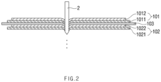
- FIG. 2 is a schematic view illustrating a state in which the nail 2 passes through the electrode assembly 10 according to the related art.
- the electrode assembly 10 To manufacture the electrode assembly 10, first, slurry of a positive electrode active material 1012 is applied to a positive electrode collector 1011, and slurry of a negative electrode active material 1022 is applied to a negative electrode collector 1021 to manufacture a positive electrode 101 and a negative electrode 102. Also, a separator 103 is disposed between the positive electrode 101 and the negative electrode 102, which are manufactured, and then, the positive electrode 101, the separator 103, and the negative electrode 102 are laminated to manufacture the electrode assembly 10 as illustrated in FIG. 1 . Although only one unit cell in which one positive electrode 101, one negative electrode 102, and one separator 103 are laminated is illustrated in FIG. 1 , the electrode assembly 10 is not limited thereto. For example, a plurality of unit cells may be further laminated.
- a secondary battery 1 When the electrode assembly 10 is accommodated in a case to be sealed, a secondary battery 1 is manufactured. However, while the secondary battery 1 is actually used, an accident may occur due to a collision with the outside. For example, a sharp object may pass through the secondary battery 1, and thus, the positive electrode 101 and the negative electrode 102 may directly contact each other to cause short circuit. Due to the short circuit, a large amount of gas may be generated at a high speed in a short time, and a high temperature rise may occur. Furthermore, large explosion may occur to lead to a major accident.
- a penetration test of a nail 2, in which the nail 2 is penetrated to determine an explosion risk is performed as one of safety tests.
- the secondary battery 1 may reach the highest temperature quickly when the positive electrode collector 1011 and the negative electrode active material 1022 contact each other, and thus, large explosion may occur.
- the contact between the positive electrode collector 1011 and the negative electrode active material 1022 is known as the most dangerous contact.
- the positive electrode 101 is laminated on the outermost side of the electrode assembly 10, as illustrated in FIG. 2 , there is a problem that possibility of occurrence of the large explosion is very high because the positive electrode collector 1011 and the negative electrode active material 1022 are the closest to each other.
- a problem to be solved by the present invention is to provide a pouch-type secondary battery that reduces a heat generation rate and easily releases heat to the outside to reduce a risk of explosion even if a sharp nail passes therethrough, and a pouch for a secondary battery.
- a pouch-type secondary battery includes: an electrode assembly (10) in which a positive electrode (101), a separator (103), and a negative electrode (102) are laminated; and a pouch comprising an upper pouch (131) and a lower pouch (132) and configured to accommodate the electrode assembly (10), wherein the pouch comprises: a surface protection layer (1352) made of a first polymer and formed at an outermost layer; a sealant layer (1353) made of a second polymer and formed at an innermost layer; a gas barrier layer (1351) made of a first metal and laminated between the surface protection layer and the sealant layer; and a metal foil layer (1354) made of a second metal, laminated between the surface protection layer and the sealant layer, and connected to the negative electrode of the electrode assembly, wherein the metal foil layer (1354) is connected to a negative electrode lead extending from the negative electrode so as to be connected to the negative electrode, and portions of the surface protection layer, the sealant layer, and the gas barrier layer
- the negative electrode lead may be welded and connected to the metal foil layer exposed through the specific area.
- the pouch-type secondary battery may further include an insulation layer, which insulates the gas barrier layer from the metal foil layer, between the gas barrier layer and the metal foil layer.
- the metal foil layer may be clad-rolled together with the gas barrier layer.
- the first polymer may include polyethylene terephthalate (PET).
- PET polyethylene terephthalate
- the first metal may include aluminum.
- the second metal may include the same kind of metal as a metal contained in a negative electrode collector of the negative electrode.
- the second metal may include copper.
- the second polymer may include polypropylene.
- a pouch for a pouch-type secondary battery which is configured to accommodate an electrode assembly in which a positive electrode, a separator, and a negative electrode are laminated, according to an embodiment of the present invention includes: a surface protection layer made of a first polymer and formed at an outermost layer; a sealant layer made of a second polymer and formed at an innermost layer; a gas barrier layer made of a first metal and laminated between the surface protection layer and the sealant layer; and a metal foil layer made of a second metal, laminated between the surface protection layer and the sealant layer, and connected to the negative electrode of the electrode assembly, wherein portions of the surface protection layer, the sealant layer, and the gas barrier layer are removed from a specific area to expose the metal foil layer to the outside and the specific area corresponds to an area on which a negative electrode lead (122) extending from the negative electrode exists in the upper pouch (131) and the lower pouch (132) when the electrode assembly is accommodated.
- the pouch for the pouch-type secondary battery may further include an insulation layer, which insulates the gas barrier layer from the metal foil layer, between the gas barrier layer and the metal foil layer.
- the metal foil layer may be clad-rolled together with the gas barrier layer.
- the embodiments of the present invention may have at least the following effects.
- the short circuit between the metal foil layer and the positive electrode active material may be induced first before the most dangerous short circuit between the positive electrode collector and the negative electrode active material to reduce the heat generation rate and easily release the heat to the outside, thereby reducing the risk of the explosion.
- FIG. 3 is an assembled view of a secondary battery 1 according to an embodiment of the present invention.
- slurry of a positive electrode active material 1012 is applied to a positive electrode collector 1011
- slurry of a negative electrode active material 1022 is applied to a negative electrode collector 1021 to manufacture a positive electrode 101 and a negative electrode 102.
- the positive electrode 101 and the negative electrode 102 may be laminated on both sides of a separator 103 to manufacture an electrode assembly 10 having a predetermined shape.
- the electrode assembly 10 may be accommodated in a battery case, and then, an electrolyte may be injected into the battery case to seal the battery case.
- the electrode assembly 10 includes an electrode tab 11.
- the electrode tab 11 is connected to each of the positive electrode 101 and the negative electrode 102 of the electrode assembly 10 to protrude to the outside of the electrode assembly 10, thereby providing a path, through which electrons move, between the inside and outside of the electrode assembly 10.
- the electrode collector of the electrode assembly 10 is constituted by a portion coated with slurry of electrode active materials 1012 and 1022 and a distal end, on which the slurry of the electrode active materials 1012 and 1022 are not applied, i.e., a non-coating portion.
- the electrode tab 11 may be formed by cutting the non-coating portion or by connecting a separate conductive member to the non-coating portion through ultrasonic welding.
- the electrode tabs 11 may protrude from one side of the electrode assembly 10 in the same direction, but the present invention is not limited thereto.
- the electrode tabs 11 may protrude in directions different from each other.
- the electrode lead 12 is connected to the electrode tab 11 through spot welding. Also, a portion of the electrode lead 12 is surrounded by an insulation part 14.
- the insulation part 14 may be disposed to be limited within a sealing part 134, to which an upper pouch 131 and a lower pouch 132 of a pouch 13 are thermally fused, so that the electrode lead 12 is bonded to the pouch 13. Also, electricity generated from the electrode assembly 10 may be prevented from flowing to the pouch 13 through the electrode lead 12, and the sealing of the pouch 13 may be maintained.
- the insulation part 14 may be made of a nonconductor having non-conductivity, which is not electrically conductive.
- the present invention is not limited thereto.
- various members may be used as the insulation part 14 as long as the members are capable of insulating the electrode lead 12.
- the insulation part 14 surrounds only the periphery of the positive electrode lead 121 of the electrode lead 12 and does not surround the periphery of the negative electrode lead 122.
- the electrode lead 12 may extend in the same direction or extend in directions different from each other according to the formation positions of the positive electrode tab 111 and the negative electrode tab 112.
- the positive electrode lead 121 and the negative electrode lead 122 may be made of materials different from each other. That is, the positive electrode lead 121 may be made of the same material as the positive electrode collector 1011, i.e., an aluminum (Al) material, and the negative electrode lead 122 may be made of the same material as the negative electrode collector, i.e., a copper-containing metal material such as a copper (Cu) material or a copper material coated with nickel (Ni).
- a portion of the electrode lead 12, which protrudes to the outside of the pouch 13, may be provided as a terminal part so as to be electrically connected to an external terminal.
- the negative electrode lead 122 is connected to a metal foil layer 1354 provided in the pouch 13. This will be described below in detail.
- the battery case may be the pouch 13 made of a flexible material.
- the pouch 13 accommodates the electrode assembly 10 so that a portion of the electrode lead 12, i.e., the terminal part is exposed and then is sealed.
- the pouch 13 includes an upper pouch 131 and a lower pouch 132.
- a cup part 133 having an accommodation space 1331 capable of accommodating the electrode assembly 10 is formed in the lower pouch 132, and the upper pouch 131 covers an upper portion of the accommodation space 1331 to prevent the electrode assembly 10 from being separated to the outside of the pouch 13.
- the cup part 133 having the accommodation space 1331 may be formed in the upper pouch 131 to accommodate the electrode assembly 10 in the upper portion.
- one side of the upper pouch 131 and one side of the lower pouch 132 may be connected to each other.
- the present invention is not limited thereto.
- the upper pouch 131 and the lower pouch may be separately manufactured to be separated from each other.
- the sealing part 134 formed on an edge may be sealed.
- some layers may be removed from a partial specific area 1341 of the sealing part 134 of the pouch 13 to expose the metal foil layer 1354.
- the negative electrode lead 122 may be easily welded and connected to the metal foil layer 1354. This will be described below in detail.
- the electrode assembly 10 when the electrode lead 12 is connected to the electrode tab 11 of the electrode assembly 10, and the insulation part 14 is formed on a portion of the electrode lead 12, particularly, the positive electrode lead 121, the electrode assembly 10 may be accommodated in the accommodation space 1331 provided in the lower pouch 132, and the upper pouch 131 may cover the upper side of the accommodation space 1331. Also, when the electrolyte is injected, and the sealing part 154 formed on the edge of each of the upper pouch 131 and the lower pouch 132 is sealed, the secondary battery 1 is manufactured.
- FIG. 4 is a partial cross-sectional view of the pouch 13 according to an embodiment of the present invention.
- the secondary battery 1 includes: an electrode assembly 10 in which a positive electrode 101, a separator 103, and a negative electrode 102 are laminated; and a pouch 13 accommodating the electrode assembly 10.
- the pouch 13 includes: a surface protection layer 1352 made of a first polymer and formed at the outermost layer; a sealant layer 1353 made of a second polymer and formed at the innermost layer; a gas barrier layer 1351 made of a first metal and laminated between the surface protection layer 1352 and the sealant layer 1353; and a metal foil layer 1354 made of a second metal, laminated between the surface protection layer 1352 and the sealant layer 1353, and connected to the negative electrode 102 of the electrode assembly 10. Also, portions of the surface protection layer 1352, the sealant layer 1353, and the gas barrier layer 1351 may be removed from a specific area 1341 of the pouch 13 to expose the metal foil layer 1354 to the outside.
- the pouch 13 is manufactured by drawing a pouch film 135. That is, the pouch film 135 is elongated by using a punch or the like to form a cup part 133, thereby manufacturing the pouch 13.
- the pouch film 135 includes the gas barrier layer 1351, the surface protection layer 1352, the sealant layer 1353, and the metal foil layer 1354.
- the gas barrier layer 1351 may secure mechanical strength of the pouch 13, block introduction and discharge of a gas or moisture outside the secondary battery 1, and prevent the electrolyte from leaking.
- the gas barrier layer 1351 is made of the first metal, and the first metal may include aluminum.
- Aluminum may secure the mechanical strength of a predetermined level or more, but be light in weight. Thus, aluminum may secure complement and heat dissipation for electrochemical properties of the electrode assembly 10 and the electrolyte.
- the present invention is not limited thereto.
- the gas barrier layer 1351 may be made of various materials.
- the gas barrier layer 1351 may be made of one material or a mixture of two or more materials selected from the group consisting of Fe, C, Cr, Mn, Ni and Al.
- the gas barrier layer 1351 is made of a material containing iron, the mechanical strength may be improved.
- the gas barrier layer 1351 is made of a material containing aluminum, flexibility may be improved.
- the material forming the gas barrier layer 1351 may be used in consideration of the characteristics of the gas barrier layer 1351.
- the surface protection layer 1352 is made of the first polymer and disposed at the outermost layer to protect the secondary battery 1 against external friction and collision and also electrically insulates the electrode assembly 10 from the outside.
- the outermost layer represents a layer disposed at the last when oriented in a direction opposite to the direction in which the electrode assembly 10 is disposed with respect to the gas barrier layer 1351.
- the first polymer forming the surface protection layer 1352 may include at least one or more materials selected from the group consisting of polyethylene, polypropylene, polycarbonate, polyethylene terephthalate (PET), polyvinyl chloride, acrylic polymer, polyacrylonitrile, polyimide, polyamide, cellulose, aramid, nylon, polyester, polyparaphenylene benzobisoxazole, polyarylate, teflon, and glass fiber.
- PET polyethylene terephthalate
- acrylic polymer polyacrylonitrile
- polyimide polyamide
- cellulose cellulose
- aramid nylon
- polyester polyparaphenylene benzobisoxazole
- polyarylate teflon
- glass fiber glass fiber.
- a polymer such as a nylon resin or polyethylene terephthalate (PET) having mainly abrasion resistance and heat resistance is used.
- the surface protection layer 1352 may have a single layer structure made of one material or a composite layer structure in which two or
- the sealant layer 1353 is made of the second polymer and disposed at the innermost layer to directly contact the electrode assembly 10.
- the innermost layer represents a layer disposed at the last when oriented in a direction opposite to the direction in which the electrode assembly 10 is disposed with respect to the gas barrier layer 1351.
- the pouch 13 having a pouch shape may be manufactured while a portion of the pouch film 135 is stretched to form the cup part 133 having the accommodation space 1331 with a bag shape when the pouch film 135 having the lamination structure as described above is drawn by using the punch or the like. Also, when the electrode assembly 10 is accommodated in the accommodation space 1331, the electrolyte is injected.
- the sealant layers 1353 may be bonded to each other to seal the pouch 13.
- the sealant layer 1353 since the sealant layer 1353 directly contacts the electrode assembly 10, the sealant layer 1353 may have to have insulating properties. Also, since the sealant layer 1353 contacts the electrolyte, the sealant layer 1353 may have to have corrosion resistance. Also, since the inside of the battery case 13 is completely sealed to prevent materials from moving between the inside and outside of the battery case 13, high sealability has to be realized. That is, the sealing part 134 in which the sealant layers 1353 are bonded to each other should have superior bonding strength.
- the second polymer forming the sealant layer 1353 may include at least one or more materials selected from the group consisting of polyethylene, polypropylene, polycarbonate, polyethylene terephthalate, polyvinyl chloride, acrylic polymer, polyacrylonitrile, polyimide, polyamide, cellulose, aramid, nylon, polyester, polyparaphenylene benzobisoxazole, polyarylate, teflon, and glass fiber.
- a polyolefin-based resin such as polypropylene (PP) or polyethylene (PE) may be used for the sealant layer 1353.
- Polypropylene (PP) is excellent in mechanical properties such as tensile strength, rigidity, surface hardness, abrasion resistance, and heat resistance and chemical properties such as corrosion resistance and thus is mainly used for manufacturing the sealant layer 1353.
- the sealant layer 1353 may be made of a casted polypropylene, an acid-treated polypropylene, or a polypropylene-butylene-ethylene terpolymer.
- the acid-treated polypropylene may be maleic anhydride polypropylene (MAH PP).
- the sealant layer 1353 may have a single layer structure made of one material or a composite layer structure in which two or more materials are respectively formed as layers.
- the metal foil layer 1354 is laminated between the surface protection layer 1352 and the sealant layer 1353 and connected to the negative electrode 102 of the electrode assembly 10.
- the metal foil layer 1354 may have a negative polarity to induce short circuit between the metal foil layer 1354 and the positive electrode active material 1012 even though the nail 2 passes therethrough, thereby reducing the risk of the explosion.
- the metal foil layer 1354 is made of the second metal, and the second metal includes the same kind of metal as the metal contained in the negative electrode collector 1021.
- the second metal may include a copper (Cu) material or a copper material coated with nickel (Ni), which is the same as that of the negative electrode collector 1021.
- the positions of the metal foil layer 1354 and the gas barrier layer 1351 may be exchanged with each other. That is, as illustrated in FIG. 4 , the metal foil layer 1354 may be disposed above the gas barrier layer 1351, but is not limited thereto. For example, the metal foil layer 1354 may be disposed below the gas barrier layer 1351. If the metal foil layer 1354 is disposed below the gas barrier layer 1351, a distance between the metal foil layer 1354 and the positive electrode active material 1012 may be more reduced so that the metal foil layer 1354 and the positive electrode active material 1012 may more easily contact each other when the nail 2 passes. However, since the metal foil layer 1354 is connected to the negative electrode 102, the metal foil layer 1354 may have a negative polarity.
- the insulation layer 1355 which insulates the metal foil layer 1354 from the gas barrier layer 1351, may be further laminated between the metal foil layer 1354 and the gas barrier layer 1351.
- the insulation layer 1355 may be provided as a nonconductor having non-conductivity, which is not electrically conductive.
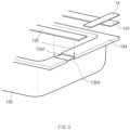
- FIG. 5 is a detailed assembled view illustrating a state in which the metal foil layer 1354 and a negative electrode lead 122 are connected to each other according to an embodiment of the present invention.
- the metal foil layer 1354 is connected to the negative electrode 102 of the electrode assembly 10, particularly, the negative electrode lead 122 extending from the negative electrode 102.
- the surface protection layer 1352, the sealant layer 1353, and the gas barrier layer 1351 are removed from the specific area 1341 of the sealing part 134 formed on the edge of the pouch 13, which corresponds to an area on which the negative electrode lead 122 exists.
- the metal foil layer 1354 may be exposed to the outside.
- the negative electrode lead 122 contacts the metal foil layer 1354 exposed through the specific area 1341 in the pouch 13.
- the negative electrode lead 122 and the metal foil layer 1354 may be easily welded to each other through laser welding or ultrasonic welding and then be connected to each other.
- the metal foil layer 1354 and the negative electrode lead 122 are exposed to the outside as well as the inside on the specific area 1341.
- the surface protection layer 1352 is removed also from the specific area 1341.
- the connection between the metal foil layer 1354 and the negative electrode lead 122 is not interrupted.
- the negative electrode lead 122 and the metal foil layer 1354 are welded to each other without removing the surface protection layer 1352, only the sealant layer 1353 and the gas barrier layer 1351 may be removed from the specific area 1341, and the surface protection layer 1352 may not be removed.
- FIG. 5 illustrates a state in which the metal foil layer 1354 is exposed on only the sealing part 134 of the lower pouch 132 and connected to the negative electrode lead 122.
- the upper pouch 131 and the lower pouch 132 may be separated from each other so as to be separately manufactured.
- a portion of the metal foil layer 1354 may be cut while being folded.
- the metal foil layer 1354 of the upper pouch 131 and the metal foil layer 1354 of the lower pouch 132 may be electrically disconnected from each other.
- the negative electrode lead 122 is connected to only the metal foil layer 1354 of the lower pouch 132, the risk of the explosion may not be reduced when the nail 2 passes from a side of the upper pouch 131.
- the surface protection layer 1352, the sealant layer 1353, and the gas barrier layer 1351 may be removed from the area corresponding to the negative electrode lead 122 in the upper pouch 131 as well as the lower pouch 132 to expose the metal foil layer 1354.
- the negative electrode lead 122 is connected to the metal foil layer 1354 on each of the top and bottom surface thereof.
- a stepped portion may be formed on the specific area 1341 of the sealing part 134 of the pouch 13.
- the insulation part 14 surrounds the periphery of the positive electrode lead 121, whereas the insulation part 14 does not surround the periphery of the negative electrode lead 122.
- the negative electrode lead 122 is directly welded and connected to the metal foil layer 1354, a deviation in sealing thickness between the positive electrode lead 121 and the negative electrode lead 122 may not be large.
- the negative electrode lead 122 may have a thickness greater than that of the positive electrode lead 121, or a protrusion protruding from the negative electrode lead 122 toward the metal foil layer 1354 may be formed to reduce the deviation.
- FIG. 6 is a schematic view illustrating a state in which the nail 2 approaches the secondary battery 1 according to an embodiment
- FIG. 7 is a schematic view illustrating a state in which the nail 2 passes through the secondary battery 1 according to an embodiment of the prevent invention.
- the metal foil layer 1354 may have a negative polarity.
- the metal foil layer 1354 and the positive electrode active material 1012 may contact each other first. That is, before the most dangerous short circuit between the positive electrode collector 1011 and the negative electrode active material 1022 occurs, the short circuit between the metal foil layer 1354 and the positive electrode active material 1012 may be induced first. Therefore, the heat generation rate may be reduced.
- the metal foil layer 1354 may be laminated all over the inside of the pouch 13. That is, the metal foil layer 1354 may have a relatively large surface area when compared to the electrode assembly 10 and be disposed at the outside. Thus, even though the metal foil layer 1354 and the positive electrode active material 1012 are short-circuited to raise a temperature of the metal foil layer 1354, heat may be easily released to the outside when compared to the short circuit that occurs within the electrode assembly 10 to raise a temperature. Therefore, the risk of the explosion may be reduced.
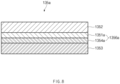
- FIG. 8 is a partial cross-sectional view of the pouch 13 according to an embodiment of the present invention.
- the metal foil layer 1354 and the gas barrier layer 1351 which are provided in the pouch film 135, may be separate layers. Also, to prevent the gas barrier layer 1351 from having the polarity, the insulation layer 1355, which insulates the metal foil layer 1354 from the gas barrier layer 1351, may be further laminated between the metal foil layer 1354 and the gas barrier layer 1351. Thus, the metal foil layer 1354 and the gas barrier layer 1351 may not be connected to each other.
- the first metal forming the gas barrier layer 1351 may be aluminum as described above.
- the aluminum has advantages that it is light in weight, has strong corrosion resistance against water or oxygen, and has weak salt resistance against salt and the like. Thus, if the sealant layer 1353 is partially broken due to deterioration of the pouch 13 or initial failure of the product, aluminum may contact the electrolyte within the pouch 13 and thus be corroded.
- a gas barrier layer 1351a and a metal foil layer 1354a which are provided in a pouch film 135a, may be clad-rolled to be mechanically bonded to each other in a state of overlapping each other, thereby forming a clad-rolled layer 1356a.
- the clad is a metal rolling method in which various metals are bonded to each other to take only advantages of each metal.
- a first metal of the gas barrier layer 1351a is disposed above a second metal of the metal foil layer 1354a.
- the second metal may be copper.
- the copper is stronger in salt water resistance than aluminum.
Landscapes
- Chemical & Material Sciences (AREA)
- Chemical Kinetics & Catalysis (AREA)
- Electrochemistry (AREA)
- General Chemical & Material Sciences (AREA)
- Inorganic Chemistry (AREA)
- Sealing Battery Cases Or Jackets (AREA)
- Connection Of Batteries Or Terminals (AREA)
- Battery Mounting, Suspending (AREA)
Description
- The present application claims the benefit of the priority of
Korean Patent Application No. 10-2018-0101950, filed on August 29, 2018 - The present invention relates to a pouch-type secondary battery, according to
claim 1 and a pouch for a pouch-type secondary battery, according toclaim 10, that reduces a heat generation rate and easily releases heat to the outside to reduce a risk of explosion even if a sharp nail passes therethrough, and a pouch for a secondary battery. - In general, secondary batteries include nickelcadmium batteries, nickel-hydrogen batteries, lithium ion batteries, and lithium ion polymer batteries. Such a secondary battery is being applied to and used in small-sized products such as digital cameras, P-DVDs, MP3Ps, mobile phones, PDAs, portable game devices, power tools, E-bikes, and the like as well as large-sized products requiring high power such as electric vehicles and hybrid vehicles, power storage devices for storing surplus power or renewable energy, and backup power storage devices.
- Such a secondary battery is classified into a pouch type secondary battery and a can type secondary battery according to a material of a case accommodating the electrode assembly. In the pouch type secondary battery, an electrode assembly is accommodated in a pouch made of a flexible polymer material. Also, in the can type secondary battery, an electrode assembly is accommodated in a case made of a metal or plastic material.
-
FIG. 1 is a schematic view illustrating a state in which anail 2 approaches anelectrode assembly 10 according to the related art, andFIG. 2 is a schematic view illustrating a state in which thenail 2 passes through theelectrode assembly 10 according to the related art. - To manufacture the
electrode assembly 10, first, slurry of a positive electrodeactive material 1012 is applied to apositive electrode collector 1011, and slurry of a negative electrodeactive material 1022 is applied to anegative electrode collector 1021 to manufacture apositive electrode 101 and anegative electrode 102. Also, aseparator 103 is disposed between thepositive electrode 101 and thenegative electrode 102, which are manufactured, and then, thepositive electrode 101, theseparator 103, and thenegative electrode 102 are laminated to manufacture theelectrode assembly 10 as illustrated inFIG. 1 . Although only one unit cell in which onepositive electrode 101, onenegative electrode 102, and oneseparator 103 are laminated is illustrated inFIG. 1 , theelectrode assembly 10 is not limited thereto. For example, a plurality of unit cells may be further laminated. - When the
electrode assembly 10 is accommodated in a case to be sealed, asecondary battery 1 is manufactured. However, while thesecondary battery 1 is actually used, an accident may occur due to a collision with the outside. For example, a sharp object may pass through thesecondary battery 1, and thus, thepositive electrode 101 and thenegative electrode 102 may directly contact each other to cause short circuit. Due to the short circuit, a large amount of gas may be generated at a high speed in a short time, and a high temperature rise may occur. Furthermore, large explosion may occur to lead to a major accident. - Thus, before the
secondary battery 1 is actually used, as illustrated inFIGS. 1 and2 , a penetration test of anail 2, in which thenail 2 is penetrated to determine an explosion risk, is performed as one of safety tests. - However, in general, when the penetration test of the
nail 2 is performed, thesecondary battery 1 may reach the highest temperature quickly when thepositive electrode collector 1011 and the negative electrodeactive material 1022 contact each other, and thus, large explosion may occur. Thus, the contact between thepositive electrode collector 1011 and the negative electrodeactive material 1022 is known as the most dangerous contact. However, if thepositive electrode 101 is laminated on the outermost side of theelectrode assembly 10, as illustrated inFIG. 2 , there is a problem that possibility of occurrence of the large explosion is very high because thepositive electrode collector 1011 and the negative electrodeactive material 1022 are the closest to each other. - A problem to be solved by the present invention is to provide a pouch-type secondary battery that reduces a heat generation rate and easily releases heat to the outside to reduce a risk of explosion even if a sharp nail passes therethrough, and a pouch for a secondary battery.
- The objects of the present invention, which is defined by the claims, are not limited to the aforementioned object, but other objects not described herein will be clearly understood by those skilled in the art from descriptions below.
- To solve the above problem, a pouch-type secondary battery according to an embodiment of the present invention includes: an electrode assembly (10) in which a positive electrode (101), a separator (103), and a negative electrode (102) are laminated; and a pouch comprising an upper pouch (131) and a lower pouch (132) and configured to accommodate the electrode assembly (10), wherein the pouch comprises: a surface protection layer (1352) made of a first polymer and formed at an outermost layer; a sealant layer (1353) made of a second polymer and formed at an innermost layer; a gas barrier layer (1351) made of a first metal and laminated between the surface protection layer and the sealant layer; and a metal foil layer (1354) made of a second metal, laminated between the surface protection layer and the sealant layer, and connected to the negative electrode of the electrode assembly, wherein the metal foil layer (1354) is connected to a negative electrode lead extending from the negative electrode so as to be connected to the negative electrode, and portions of the surface protection layer, the sealant layer, and the gas barrier layer are removed from a specific area corresponding to an area on which the negative electrode lead exists in the upper pouch (131) and the lower pouch (132).
- .
- Also, the negative electrode lead may be welded and connected to the metal foil layer exposed through the specific area.
- Also, the pouch-type secondary battery may further include an insulation layer, which insulates the gas barrier layer from the metal foil layer, between the gas barrier layer and the metal foil layer.
- Also, the metal foil layer may be clad-rolled together with the gas barrier layer.
- Also, the first polymer may include polyethylene terephthalate (PET).
- Also, the first metal may include aluminum.
- Also, the second metal may include the same kind of metal as a metal contained in a negative electrode collector of the negative electrode.
- Also, the second metal may include copper.
- Also, the second polymer may include polypropylene.
- To solve the above problem, a pouch for a pouch-type secondary battery, which is configured to accommodate an electrode assembly in which a positive electrode, a separator, and a negative electrode are laminated, according to an embodiment of the present invention includes: a surface protection layer made of a first polymer and formed at an outermost layer; a sealant layer made of a second polymer and formed at an innermost layer; a gas barrier layer made of a first metal and laminated between the surface protection layer and the sealant layer; and a metal foil layer made of a second metal, laminated between the surface protection layer and the sealant layer, and connected to the negative electrode of the electrode assembly, wherein portions of the surface protection layer, the sealant layer, and the gas barrier layer are removed from a specific area to expose the metal foil layer to the outside and the specific area corresponds to an area on which a negative electrode lead (122) extending from the negative electrode exists in the upper pouch (131) and the lower pouch (132) when the electrode assembly is accommodated.
- Also, the pouch for the pouch-type secondary battery may further include an insulation layer, which insulates the gas barrier layer from the metal foil layer, between the gas barrier layer and the metal foil layer.
- Also, the metal foil layer may be clad-rolled together with the gas barrier layer.
- Particularities of other embodiments are included in the detailed description and drawings.
- The embodiments of the present invention may have at least the following effects.
- Even though the sharp nail passes through the secondary battery, the short circuit between the metal foil layer and the positive electrode active material may be induced first before the most dangerous short circuit between the positive electrode collector and the negative electrode active material to reduce the heat generation rate and easily release the heat to the outside, thereby reducing the risk of the explosion.
- The effects of the prevent invention are not limited by the aforementioned description, and thus, more varied effects are involved in this specification.
-
-
FIG. 1 is a schematic view illustrating a state in which a nail approaches an electrode assembly according to a related art. -
FIG. 2 is a schematic view illustrating a state in which the nail passes through the electrode assembly according to the related art. -
FIG. 3 is an assembled view of a secondary battery according to an embodiment of the present invention. -
FIG. 4 is a cross-sectional view illustrating a portion of a pouch according to an embodiment of the present invention. -
FIG. 5 is a detailed view illustrating a state in which a metal foil layer and a negative electrode lead are connected to each other according to an embodiment of the present invention. -
FIG. 6 is a schematic view illustrating a state in which a nail approaches the secondary battery according to an embodiment of the prevent invention. -
FIG. 7 is a schematic view illustrating a state in which the nail passes through the secondary battery according to an embodiment of the prevent invention. -
FIG. 8 is a cross-sectional view illustrating a portion of a pouch according to another embodiment of the present invention. - Advantages and features of the present disclosure, and implementation methods thereof will be clarified through following embodiments described with reference to the accompanying drawings. The present invention may, however be embodied in different forms and should not be construed as limited to the embodiments set forth herein. Rather, these embodiments are provided so that this disclosure will be thorough and complete, and will fully convey the scope of the present invention to those skilled in the art. Further, the present invention is only defined by scopes of claims. Like reference numerals refer to like elements throughout.
- Unless terms used in the present invention are defined differently, all terms (including technical and scientific terms) used herein have the same meaning as generally understood by those skilled in the art. Also, unless defined clearly and apparently in the description, the terms as defined in a commonly used dictionary are not ideally or excessively construed as having formal meaning.
- In the following description, the technical terms are used only for explaining a specific exemplary embodiment while not limiting the present invention. In this specification, the terms of a singular form may comprise plural forms unless specifically mentioned. The meaning of "comprises" and/or "comprising" does not exclude other components besides a mentioned component.
- Hereinafter, preferred embodiments will be described in detail with reference to the accompanying drawings.
-
FIG. 3 is an assembled view of asecondary battery 1 according to an embodiment of the present invention. - To manufacture the
secondary battery 1 according to an embodiment of the present invention, first, slurry of a positive electrodeactive material 1012 is applied to apositive electrode collector 1011, and slurry of a negative electrodeactive material 1022 is applied to anegative electrode collector 1021 to manufacture apositive electrode 101 and anegative electrode 102. Also, thepositive electrode 101 and thenegative electrode 102 may be laminated on both sides of aseparator 103 to manufacture anelectrode assembly 10 having a predetermined shape. Also, theelectrode assembly 10 may be accommodated in a battery case, and then, an electrolyte may be injected into the battery case to seal the battery case. - As illustrated in
FIG. 3 , theelectrode assembly 10 includes anelectrode tab 11. Theelectrode tab 11 is connected to each of thepositive electrode 101 and thenegative electrode 102 of theelectrode assembly 10 to protrude to the outside of theelectrode assembly 10, thereby providing a path, through which electrons move, between the inside and outside of theelectrode assembly 10. The electrode collector of theelectrode assembly 10 is constituted by a portion coated with slurry of electrodeactive materials active materials electrode tab 11 may be formed by cutting the non-coating portion or by connecting a separate conductive member to the non-coating portion through ultrasonic welding. As illustrated inFIG. 1 , theelectrode tabs 11 may protrude from one side of theelectrode assembly 10 in the same direction, but the present invention is not limited thereto. For example, theelectrode tabs 11 may protrude in directions different from each other. - In the
electrode assembly 10, theelectrode lead 12 is connected to theelectrode tab 11 through spot welding. Also, a portion of theelectrode lead 12 is surrounded by aninsulation part 14. Theinsulation part 14 may be disposed to be limited within a sealingpart 134, to which anupper pouch 131 and alower pouch 132 of apouch 13 are thermally fused, so that theelectrode lead 12 is bonded to thepouch 13. Also, electricity generated from theelectrode assembly 10 may be prevented from flowing to thepouch 13 through theelectrode lead 12, and the sealing of thepouch 13 may be maintained. Thus, theinsulation part 14 may be made of a nonconductor having non-conductivity, which is not electrically conductive. In general, although an insulation tape which is easily attached to theelectrode lead 12 and has a relatively thin thickness is mainly used as theinsulation part 14, the present invention is not limited thereto. For example, various members may be used as theinsulation part 14 as long as the members are capable of insulating theelectrode lead 12. However, according to an embodiment of the present invention, it is preferable that theinsulation part 14 surrounds only the periphery of thepositive electrode lead 121 of theelectrode lead 12 and does not surround the periphery of thenegative electrode lead 122. - The
electrode lead 12 may extend in the same direction or extend in directions different from each other according to the formation positions of thepositive electrode tab 111 and thenegative electrode tab 112. Thepositive electrode lead 121 and thenegative electrode lead 122 may be made of materials different from each other. That is, thepositive electrode lead 121 may be made of the same material as thepositive electrode collector 1011, i.e., an aluminum (Al) material, and thenegative electrode lead 122 may be made of the same material as the negative electrode collector, i.e., a copper-containing metal material such as a copper (Cu) material or a copper material coated with nickel (Ni). Also, a portion of theelectrode lead 12, which protrudes to the outside of thepouch 13, may be provided as a terminal part so as to be electrically connected to an external terminal. Also, according to an embodiment of the present invention, thenegative electrode lead 122 is connected to ametal foil layer 1354 provided in thepouch 13. This will be described below in detail. - In the pouch-type
secondary battery 1 according to an embodiment of the present invention, the battery case may be thepouch 13 made of a flexible material. Hereinafter, it is explained that the battery case is thepouch 13. Also, thepouch 13 accommodates theelectrode assembly 10 so that a portion of theelectrode lead 12, i.e., the terminal part is exposed and then is sealed. As illustrated inFIG. 3 , thepouch 13 includes anupper pouch 131 and alower pouch 132. Acup part 133 having anaccommodation space 1331 capable of accommodating theelectrode assembly 10 is formed in thelower pouch 132, and theupper pouch 131 covers an upper portion of theaccommodation space 1331 to prevent theelectrode assembly 10 from being separated to the outside of thepouch 13. Here, as illustrated inFIG. 3 , thecup part 133 having theaccommodation space 1331 may be formed in theupper pouch 131 to accommodate theelectrode assembly 10 in the upper portion. As illustrated inFIG. 3 , one side of theupper pouch 131 and one side of thelower pouch 132 may be connected to each other. However, the present invention is not limited thereto. For example, theupper pouch 131 and the lower pouch may be separately manufactured to be separated from each other. - After the
upper pouch 131 and thelower pouch 132 of thepouch 13 contact each other, the sealingpart 134 formed on an edge may be sealed. Here, according to an embodiment of the present invention, some layers may be removed from a partialspecific area 1341 of the sealingpart 134 of thepouch 13 to expose themetal foil layer 1354. Thus, thenegative electrode lead 122 may be easily welded and connected to themetal foil layer 1354. This will be described below in detail. - As described above, when the
electrode lead 12 is connected to theelectrode tab 11 of theelectrode assembly 10, and theinsulation part 14 is formed on a portion of theelectrode lead 12, particularly, thepositive electrode lead 121, theelectrode assembly 10 may be accommodated in theaccommodation space 1331 provided in thelower pouch 132, and theupper pouch 131 may cover the upper side of theaccommodation space 1331. Also, when the electrolyte is injected, and the sealing part 154 formed on the edge of each of theupper pouch 131 and thelower pouch 132 is sealed, thesecondary battery 1 is manufactured. -
FIG. 4 is a partial cross-sectional view of thepouch 13 according to an embodiment of the present invention. - According to an embodiment of the present invention, even though the
sharp nail 2 passes through thesecondary battery 1, a heat generation rate may be reduced, and heat may be easily released to the outside to reduce a risk of explosion. For this, thesecondary battery 1 according to an embodiment of the present invention includes: anelectrode assembly 10 in which apositive electrode 101, aseparator 103, and anegative electrode 102 are laminated; and apouch 13 accommodating theelectrode assembly 10. Thepouch 13 includes: asurface protection layer 1352 made of a first polymer and formed at the outermost layer; asealant layer 1353 made of a second polymer and formed at the innermost layer; agas barrier layer 1351 made of a first metal and laminated between thesurface protection layer 1352 and thesealant layer 1353; and ametal foil layer 1354 made of a second metal, laminated between thesurface protection layer 1352 and thesealant layer 1353, and connected to thenegative electrode 102 of theelectrode assembly 10. Also, portions of thesurface protection layer 1352, thesealant layer 1353, and thegas barrier layer 1351 may be removed from aspecific area 1341 of thepouch 13 to expose themetal foil layer 1354 to the outside. - The
pouch 13 is manufactured by drawing apouch film 135. That is, thepouch film 135 is elongated by using a punch or the like to form acup part 133, thereby manufacturing thepouch 13. According to an embodiment of the present invention, as illustrated inFIG. 4 , thepouch film 135 includes thegas barrier layer 1351, thesurface protection layer 1352, thesealant layer 1353, and themetal foil layer 1354. - The
gas barrier layer 1351 may secure mechanical strength of thepouch 13, block introduction and discharge of a gas or moisture outside thesecondary battery 1, and prevent the electrolyte from leaking. In general, thegas barrier layer 1351 is made of the first metal, and the first metal may include aluminum. Aluminum may secure the mechanical strength of a predetermined level or more, but be light in weight. Thus, aluminum may secure complement and heat dissipation for electrochemical properties of theelectrode assembly 10 and the electrolyte. However, the present invention is not limited thereto. For example, thegas barrier layer 1351 may be made of various materials. For example, thegas barrier layer 1351 may be made of one material or a mixture of two or more materials selected from the group consisting of Fe, C, Cr, Mn, Ni and Al. Here, thegas barrier layer 1351 is made of a material containing iron, the mechanical strength may be improved. When thegas barrier layer 1351 is made of a material containing aluminum, flexibility may be improved. Thus, the material forming thegas barrier layer 1351 may be used in consideration of the characteristics of thegas barrier layer 1351. - The
surface protection layer 1352 is made of the first polymer and disposed at the outermost layer to protect thesecondary battery 1 against external friction and collision and also electrically insulates theelectrode assembly 10 from the outside. Here, the outermost layer represents a layer disposed at the last when oriented in a direction opposite to the direction in which theelectrode assembly 10 is disposed with respect to thegas barrier layer 1351. The first polymer forming thesurface protection layer 1352 may include at least one or more materials selected from the group consisting of polyethylene, polypropylene, polycarbonate, polyethylene terephthalate (PET), polyvinyl chloride, acrylic polymer, polyacrylonitrile, polyimide, polyamide, cellulose, aramid, nylon, polyester, polyparaphenylene benzobisoxazole, polyarylate, teflon, and glass fiber. Particularly, a polymer such as a nylon resin or polyethylene terephthalate (PET) having mainly abrasion resistance and heat resistance is used. Also, thesurface protection layer 1352 may have a single layer structure made of one material or a composite layer structure in which two or more materials are respectively formed as layers. - The
sealant layer 1353 is made of the second polymer and disposed at the innermost layer to directly contact theelectrode assembly 10. Here, the innermost layer represents a layer disposed at the last when oriented in a direction opposite to the direction in which theelectrode assembly 10 is disposed with respect to thegas barrier layer 1351. Thepouch 13 having a pouch shape may be manufactured while a portion of thepouch film 135 is stretched to form thecup part 133 having theaccommodation space 1331 with a bag shape when thepouch film 135 having the lamination structure as described above is drawn by using the punch or the like. Also, when theelectrode assembly 10 is accommodated in theaccommodation space 1331, the electrolyte is injected. Thereafter, when theupper pouch 131 and thelower pouch 132 may contact each other, and thermal compression is applied to the sealingpart 134, thesealant layers 1353 may be bonded to each other to seal thepouch 13. Here, since thesealant layer 1353 directly contacts theelectrode assembly 10, thesealant layer 1353 may have to have insulating properties. Also, since thesealant layer 1353 contacts the electrolyte, thesealant layer 1353 may have to have corrosion resistance. Also, since the inside of thebattery case 13 is completely sealed to prevent materials from moving between the inside and outside of thebattery case 13, high sealability has to be realized. That is, the sealingpart 134 in which thesealant layers 1353 are bonded to each other should have superior bonding strength. In general, the second polymer forming thesealant layer 1353 may include at least one or more materials selected from the group consisting of polyethylene, polypropylene, polycarbonate, polyethylene terephthalate, polyvinyl chloride, acrylic polymer, polyacrylonitrile, polyimide, polyamide, cellulose, aramid, nylon, polyester, polyparaphenylene benzobisoxazole, polyarylate, teflon, and glass fiber. Particularly, a polyolefin-based resin such as polypropylene (PP) or polyethylene (PE) may be used for thesealant layer 1353. Polypropylene (PP) is excellent in mechanical properties such as tensile strength, rigidity, surface hardness, abrasion resistance, and heat resistance and chemical properties such as corrosion resistance and thus is mainly used for manufacturing thesealant layer 1353. Furthermore, thesealant layer 1353 may be made of a casted polypropylene, an acid-treated polypropylene, or a polypropylene-butylene-ethylene terpolymer. Here, the acid-treated polypropylene may be maleic anhydride polypropylene (MAH PP). Also, thesealant layer 1353 may have a single layer structure made of one material or a composite layer structure in which two or more materials are respectively formed as layers. - Like the
gas barrier layer 1351, themetal foil layer 1354 is laminated between thesurface protection layer 1352 and thesealant layer 1353 and connected to thenegative electrode 102 of theelectrode assembly 10. Thus, themetal foil layer 1354 may have a negative polarity to induce short circuit between themetal foil layer 1354 and the positive electrodeactive material 1012 even though thenail 2 passes therethrough, thereby reducing the risk of the explosion. For this, themetal foil layer 1354 is made of the second metal, and the second metal includes the same kind of metal as the metal contained in thenegative electrode collector 1021. For example, the second metal may include a copper (Cu) material or a copper material coated with nickel (Ni), which is the same as that of thenegative electrode collector 1021. The positions of themetal foil layer 1354 and thegas barrier layer 1351 may be exchanged with each other. That is, as illustrated inFIG. 4 , themetal foil layer 1354 may be disposed above thegas barrier layer 1351, but is not limited thereto. For example, themetal foil layer 1354 may be disposed below thegas barrier layer 1351. If themetal foil layer 1354 is disposed below thegas barrier layer 1351, a distance between themetal foil layer 1354 and the positive electrodeactive material 1012 may be more reduced so that themetal foil layer 1354 and the positive electrodeactive material 1012 may more easily contact each other when thenail 2 passes. However, since themetal foil layer 1354 is connected to thenegative electrode 102, themetal foil layer 1354 may have a negative polarity. Thus, according to an embodiment of the present invention, to prevent thegas barrier layer 1351 from having the polarity, theinsulation layer 1355, which insulates themetal foil layer 1354 from thegas barrier layer 1351, may be further laminated between themetal foil layer 1354 and thegas barrier layer 1351. Theinsulation layer 1355 may be provided as a nonconductor having non-conductivity, which is not electrically conductive. Hereinafter, as illustrated inFIG. 4 , the structure in which themetal foil layer 1354 is disposed above thegas barrier layer 1351 will be described. -
FIG. 5 is a detailed assembled view illustrating a state in which themetal foil layer 1354 and anegative electrode lead 122 are connected to each other according to an embodiment of the present invention. - As described above, the
metal foil layer 1354 is connected to thenegative electrode 102 of theelectrode assembly 10, particularly, thenegative electrode lead 122 extending from thenegative electrode 102. Particularly, thesurface protection layer 1352, thesealant layer 1353, and thegas barrier layer 1351 are removed from thespecific area 1341 of the sealingpart 134 formed on the edge of thepouch 13, which corresponds to an area on which thenegative electrode lead 122 exists. As a result, themetal foil layer 1354 may be exposed to the outside. Also, thenegative electrode lead 122 contacts themetal foil layer 1354 exposed through thespecific area 1341 in thepouch 13. Also, thenegative electrode lead 122 and themetal foil layer 1354 may be easily welded to each other through laser welding or ultrasonic welding and then be connected to each other. - To easily weld the
metal foil layer 1354 and thenegative electrode lead 122 to each other through the laser welding, it is preferable that themetal foil layer 1354 is exposed to the outside as well as the inside on thespecific area 1341. Thus, it is preferable that thesurface protection layer 1352 is removed also from thespecific area 1341. However, since thesurface protection layer 1352 exists on the outside with respect to themetal foil layer 1352, the connection between themetal foil layer 1354 and thenegative electrode lead 122 is not interrupted. Thus, if thenegative electrode lead 122 and themetal foil layer 1354 are welded to each other without removing thesurface protection layer 1352, only thesealant layer 1353 and thegas barrier layer 1351 may be removed from thespecific area 1341, and thesurface protection layer 1352 may not be removed. -
FIG. 5 illustrates a state in which themetal foil layer 1354 is exposed on only the sealingpart 134 of thelower pouch 132 and connected to thenegative electrode lead 122. However, as described above, theupper pouch 131 and thelower pouch 132 may be separated from each other so as to be separately manufactured. Alternatively, even though one side of theupper pouch 131 and one side of thelower pouch 132 are connected to each other so as to be manufactured, a portion of themetal foil layer 1354 may be cut while being folded. For these various reasons, themetal foil layer 1354 of theupper pouch 131 and themetal foil layer 1354 of thelower pouch 132 may be electrically disconnected from each other. However, if thenegative electrode lead 122 is connected to only themetal foil layer 1354 of thelower pouch 132, the risk of the explosion may not be reduced when thenail 2 passes from a side of theupper pouch 131. Thus, according to an embodiment of the present invention, as illustrated inFIG. 3 , thesurface protection layer 1352, thesealant layer 1353, and thegas barrier layer 1351 may be removed from the area corresponding to thenegative electrode lead 122 in theupper pouch 131 as well as thelower pouch 132 to expose themetal foil layer 1354. Also, thenegative electrode lead 122 is connected to themetal foil layer 1354 on each of the top and bottom surface thereof. - Since the
surface protection layer 1352, thesealant layer 1353, and thegas barrier layer 1351 is removed from the area corresponding to thenegative electrode lead 122, a stepped portion may be formed on thespecific area 1341 of the sealingpart 134 of thepouch 13. However, theinsulation part 14 surrounds the periphery of thepositive electrode lead 121, whereas theinsulation part 14 does not surround the periphery of thenegative electrode lead 122. Thus, even though thenegative electrode lead 122 is directly welded and connected to themetal foil layer 1354, a deviation in sealing thickness between thepositive electrode lead 121 and thenegative electrode lead 122 may not be large. However, for example, in the case in which many layers are removed from the area corresponding to thenegative electrode lead 122, or theinsulation part 14 does not surround the periphery of thepositive electrode lead 121, if thenegative electrode lead 122 is directly welded to themetal foil layer 1354, the deviation in sealing thickness between thepositive electrode lead 121 and thenegative electrode lead 122 may be large. Thus, in this case, thenegative electrode lead 122 may have a thickness greater than that of thepositive electrode lead 121, or a protrusion protruding from thenegative electrode lead 122 toward themetal foil layer 1354 may be formed to reduce the deviation. -
FIG. 6 is a schematic view illustrating a state in which thenail 2 approaches thesecondary battery 1 according to an embodiment, andFIG. 7 is a schematic view illustrating a state in which thenail 2 passes through thesecondary battery 1 according to an embodiment of the prevent invention. - As described above, since the
metal foil layer 1354 is provided in thepouch 13, and thenegative electrode lead 122 is connected to themetal foil layer 1354, themetal foil layer 1354 may have a negative polarity. Thus, as illustrated inFIGS. 6 and7 , even though thesharp nail 2 passes through thesecondary battery 1, themetal foil layer 1354 and the positive electrodeactive material 1012 may contact each other first. That is, before the most dangerous short circuit between thepositive electrode collector 1011 and the negative electrodeactive material 1022 occurs, the short circuit between themetal foil layer 1354 and the positive electrodeactive material 1012 may be induced first. Therefore, the heat generation rate may be reduced. - Also, the
metal foil layer 1354 may be laminated all over the inside of thepouch 13. That is, themetal foil layer 1354 may have a relatively large surface area when compared to theelectrode assembly 10 and be disposed at the outside. Thus, even though themetal foil layer 1354 and the positive electrodeactive material 1012 are short-circuited to raise a temperature of themetal foil layer 1354, heat may be easily released to the outside when compared to the short circuit that occurs within theelectrode assembly 10 to raise a temperature. Therefore, the risk of the explosion may be reduced. -
FIG. 8 is a partial cross-sectional view of thepouch 13 according to an embodiment of the present invention. - According to an embodiment of the present invention, the
metal foil layer 1354 and thegas barrier layer 1351, which are provided in thepouch film 135, may be separate layers. Also, to prevent thegas barrier layer 1351 from having the polarity, theinsulation layer 1355, which insulates themetal foil layer 1354 from thegas barrier layer 1351, may be further laminated between themetal foil layer 1354 and thegas barrier layer 1351. Thus, themetal foil layer 1354 and thegas barrier layer 1351 may not be connected to each other. - However, the first metal forming the
gas barrier layer 1351 may be aluminum as described above. The aluminum has advantages that it is light in weight, has strong corrosion resistance against water or oxygen, and has weak salt resistance against salt and the like. Thus, if thesealant layer 1353 is partially broken due to deterioration of thepouch 13 or initial failure of the product, aluminum may contact the electrolyte within thepouch 13 and thus be corroded. - According to another embodiment of the present invention, a
gas barrier layer 1351a and ametal foil layer 1354a, which are provided in apouch film 135a, may be clad-rolled to be mechanically bonded to each other in a state of overlapping each other, thereby forming a clad-rolledlayer 1356a. The clad is a metal rolling method in which various metals are bonded to each other to take only advantages of each metal. Here, as illustrated inFIG. 8 , it is preferable that a first metal of thegas barrier layer 1351a is disposed above a second metal of themetal foil layer 1354a. - As described above, the second metal may be copper. The copper is stronger in salt water resistance than aluminum. Thus, if the
gas barrier layer 1351a and themetal foil layer 1354 are clad-rolled, even if thesealant layer 1353 is partially broken, thegas barrier layer 1351 may be prevented from being corroded by the electrolyte. - Those with ordinary skill in the technical field of the present invention pertains will be understood that the present invention can be carried out in other specific forms without changing the technical idea or essential features. Therefore, the above-disclosed embodiments are to be considered illustrative and not restrictive. Accordingly, the scope of the present invention is defined by the appended claims rather than the foregoing description and the exemplary embodiments described therein. Various modifications made within the meaning of an equivalent of the claims.
Claims (11)
- A pouch-type secondary battery comprising:an electrode assembly (10) in which a positive electrode (101), a separator (103), and a negative electrode (102) are laminated; anda pouch comprising an upper pouch (131) and a lower pouch (132) and configured to accommodate the electrode assembly (10),wherein the pouch comprises:a surface protection layer (1352) made of a first polymer and formed at an outermost layer;a sealant layer (1353) made of a second polymer and formed at an innermost layer;a gas barrier layer (1351) made of a first metal and laminated between the surface protection layer and the sealant layer; anda metal foil layer (1354) made of a second metal, laminated between the surface protection layer and the sealant layer, and connected to the negative electrode of the electrode assembly,wherein the metal foil layer (1354) is connected to a negative electrode lead extending from the negative electrode so as to be connected to the negative electrode, andportions of the surface protection layer, the sealant layer, and the gas barrier layer are removed from a specific area corresponding to an area on which the negative electrode lead exists in the upper pouch (131) and the lower pouch (132) .
- The pouch-type secondary battery of claim 1, wherein the negative electrode lead (122) is configured to be welded and connected to the metal foil layer (1354) exposed through the specific area.
- The pouch-type secondary battery of claim 1, further comprising an insulation layer (1355), which insulates the gas barrier layer (1351) from the metal foil layer (1354), between the gas barrier layer (1351) and the metal foil layer (1354).
- The pouch-type secondary battery of claim 1, wherein the metal foil layer (1354) is configured to be clad-rolled together with the gas barrier layer (1351).
- The pouch-type secondary battery of claim 1, wherein the first polymer comprises polyethylene terephthalate (PET).
- The pouch-type secondary battery of claim 1, wherein the first metal comprises aluminum.
- The pouch-type secondary battery of claim 1, wherein the second metal comprises the same kind of metal as a metal contained in a negative electrode collector (1021) of the negative electrode.
- The pouch-type secondary battery of claim 7, wherein the second metal comprises copper.
- The pouch-type secondary battery of claim 1, wherein the second polymer comprises polypropylene.
- A pouch for a pouch-type secondary battery, which is intended to accommodate an electrode assembly in which a positive electrode (101), a separator (103), and a negative electrode (102) are laminated, the pouch comprising an upper pouch (131) and a lower pouch (132) and comprising:a surface protection layer (1352) made of a first polymer and formed at an outermost layer;a sealant layer (1353) made of a second polymer and formed at an innermost layer;a gas barrier layer (1351) made of a first metal and laminated between the surface protection layer and the sealant layer; anda metal foil layer (1354) made of a second metal, laminated between the surface protection layer and the sealant layer, and connected to the negative electrode of the electrode assembly,wherein portions of the surface protection layer, the sealant layer, and the gas barrier layer are removed from a specific area to expose the metal foil layer to the outside, andthe specific area corresponds to an area on which a negative electrode lead (122) extending from the negative electrode exists in the upper pouch (131) and the lower pouch (132) when the electrode assembly is accommodated.
- The pouch of claim 10, further comprising an insulation layer (1355), which insulates the gas barrier layer (1351) from the metal foil layer (1354), between the gas barrier layer and the metal foil layer.
Applications Claiming Priority (2)
| Application Number | Priority Date | Filing Date | Title |
|---|---|---|---|
| KR1020180101950A KR102325036B1 (en) | 2018-08-29 | 2018-08-29 | The Pouch Type Secondary Battery And The Pouch For The Secondary Battery |
| PCT/KR2019/008076 WO2020045814A1 (en) | 2018-08-29 | 2019-07-02 | Pouch-type secondary battery and pouch for secondary battery |
Publications (3)
| Publication Number | Publication Date |
|---|---|
| EP3671886A1 EP3671886A1 (en) | 2020-06-24 |
| EP3671886A4 EP3671886A4 (en) | 2020-12-23 |
| EP3671886B1 true EP3671886B1 (en) | 2024-05-15 |
Family
ID=69644536
Family Applications (1)
| Application Number | Title | Priority Date | Filing Date |
|---|---|---|---|
| EP19854713.5A Active EP3671886B1 (en) | 2018-08-29 | 2019-07-02 | Pouch-type secondary battery and pouch for secondary battery |
Country Status (7)
| Country | Link |
|---|---|
| US (1) | US11682809B2 (en) |
| EP (1) | EP3671886B1 (en) |
| JP (1) | JP7049550B2 (en) |
| KR (1) | KR102325036B1 (en) |
| CN (1) | CN111108622B (en) |
| TW (2) | TW202010166A (en) |
| WO (1) | WO2020045814A1 (en) |
Families Citing this family (4)
| Publication number | Priority date | Publication date | Assignee | Title |
|---|---|---|---|---|
| US20230089546A1 (en) * | 2020-04-14 | 2023-03-23 | Lg Energy Solution, Ltd. | Pouch Type Battery Case and Pouch Type Secondary Battery |
| CN113782878A (en) * | 2020-06-09 | 2021-12-10 | 株式会社Lg化学 | Pouch film, pouch-type battery case, and pouch-type secondary battery |
| KR20220063370A (en) * | 2020-11-10 | 2022-05-17 | 주식회사 엘지에너지솔루션 | Battery pack in which circuit board and electrode leads are directly bonded by laser welding |
| KR20240027809A (en) * | 2021-08-11 | 2024-03-04 | 가부시키가이샤 레조낙·패키징 | Exterior materials for all-solid-state batteries and all-solid-state batteries |
Family Cites Families (33)
| Publication number | Priority date | Publication date | Assignee | Title |
|---|---|---|---|---|
| US6632538B1 (en) * | 1998-02-05 | 2003-10-14 | Dai Nippon Printing Co., Ltd. | Sheet for cell and cell device |
| JP2000251857A (en) | 1999-03-02 | 2000-09-14 | Mitsubishi Chemicals Corp | Nonaqueous secondary battery |
| JP2001297795A (en) | 2000-04-11 | 2001-10-26 | Mitsubishi Chemicals Corp | Battery |
| KR100544119B1 (en) | 2003-06-24 | 2006-01-23 | 삼성에스디아이 주식회사 | Pouched-type lithium secondary battery |
| TWI251363B (en) | 2003-07-11 | 2006-03-11 | Lg Chemical Ltd | Secondary battery with an improved safety |
| JP2005183051A (en) | 2003-12-16 | 2005-07-07 | Mitsubishi Electric Corp | Battery |
| US8722235B2 (en) | 2004-04-21 | 2014-05-13 | Blue Spark Technologies, Inc. | Thin printable flexible electrochemical cell and method of making the same |
| KR101089161B1 (en) | 2007-12-17 | 2011-12-02 | 주식회사 엘지화학 | Pouch type Secondary battery |
| KR101405621B1 (en) | 2008-01-08 | 2014-06-10 | 주식회사 엘지화학 | Pouch for secondary battery and Secondary battery using the same |
| KR101065379B1 (en) * | 2009-07-10 | 2011-09-16 | 삼성에스디아이 주식회사 | Battery module |
| KR101183557B1 (en) | 2009-12-21 | 2012-09-17 | 주식회사 이아이지 | Case for electrochemical device with a flame retardant and heat resistant material and electrochemical device comprising thereof |
| US8518569B2 (en) * | 2010-03-01 | 2013-08-27 | Apple Inc. | Integrated frame battery cell |
| US8551633B2 (en) | 2011-08-18 | 2013-10-08 | Samsung Sdi Co., Ltd. | Secondary battery |
| JP2013222687A (en) * | 2012-04-19 | 2013-10-28 | Gs Yuasa Corp | Battery |
| JP2014086361A (en) | 2012-10-26 | 2014-05-12 | Toray Advanced Film Co Ltd | Aluminum foil laminate sheet for secondary battery exterior material and secondary battery exterior material |
| KR20140059650A (en) * | 2012-11-08 | 2014-05-16 | 주식회사 엘지화학 | Safety-enhanced pouch for secondary battery and secondary battery using the same |
| KR20140147041A (en) * | 2013-06-18 | 2014-12-29 | 주식회사 엘지화학 | Cell packing material and method for manufacturing the same |
| KR20140148121A (en) * | 2013-06-21 | 2014-12-31 | 주식회사 엘지화학 | Pouch case and secondary battery including the same |
| JP6492402B2 (en) | 2014-02-18 | 2019-04-03 | 凸版印刷株式会社 | Power storage device exterior materials |
| US10290839B2 (en) * | 2014-04-25 | 2019-05-14 | Nec Energy Devices, Ltd. | Secondary battery |
| JP6629514B2 (en) * | 2014-05-08 | 2020-01-15 | 昭和電工パッケージング株式会社 | Manufacturing method of laminate exterior material |
| JP6426934B2 (en) * | 2014-07-29 | 2018-11-21 | 昭和電工パッケージング株式会社 | Electrochemical device and method of manufacturing the same |
| KR101744120B1 (en) | 2014-08-11 | 2017-06-07 | 주식회사 엘지화학 | Pouch-typed Secondary Battery of Improved Safety of Nail Penetration Test |
| JP6412388B2 (en) | 2014-09-30 | 2018-10-24 | 昭和電工パッケージング株式会社 | Molding packaging material |
| KR101883536B1 (en) | 2015-04-29 | 2018-07-30 | 주식회사 엘지화학 | Pouch type secondary battery and method of fabricating the same |
| JP2017041390A (en) | 2015-08-21 | 2017-02-23 | 昭和電工パッケージング株式会社 | Laminate exterior material |
| US20180366692A1 (en) | 2015-12-25 | 2018-12-20 | Panasonic Intellectual Property Management Co., Ltd. | Film material for battery sheathing and flexible battery including the same |
| KR102065128B1 (en) * | 2016-03-29 | 2020-01-10 | 주식회사 엘지화학 | Pouch type secondary battery |
| CN105742529A (en) * | 2016-04-14 | 2016-07-06 | 东莞新能源科技有限公司 | Composite membrane for package of lithium ion battery, package shell of lithium ion battery and fabrication method of package shell |
| KR101966359B1 (en) | 2016-09-13 | 2019-04-08 | 주식회사 엘지화학 | Secondary battery |
| KR101905991B1 (en) * | 2016-10-26 | 2018-10-08 | 현대자동차주식회사 | Pouch type battery cell with enhanced safety against piercing |
| KR102334019B1 (en) * | 2017-10-17 | 2021-12-02 | 주식회사 엘지에너지솔루션 | Battery Case Comprising Multi-Metal Barrier and Battery Cell Comprising the Same |
| CN207381438U (en) | 2017-10-30 | 2018-05-18 | 东莞市卓越新材料科技有限公司 | Corrosion resistant copper plastic film |
-
2018
- 2018-08-29 KR KR1020180101950A patent/KR102325036B1/en active IP Right Grant
-
2019
- 2019-07-02 WO PCT/KR2019/008076 patent/WO2020045814A1/en unknown
- 2019-07-02 CN CN201980004498.XA patent/CN111108622B/en active Active
- 2019-07-02 JP JP2020519971A patent/JP7049550B2/en active Active
- 2019-07-02 EP EP19854713.5A patent/EP3671886B1/en active Active
- 2019-07-02 US US16/755,796 patent/US11682809B2/en active Active
- 2019-07-11 TW TW108124446A patent/TW202010166A/en unknown
- 2019-07-11 TW TW112121451A patent/TW202339337A/en unknown
Also Published As
| Publication number | Publication date |
|---|---|
| WO2020045814A1 (en) | 2020-03-05 |
| TW202339337A (en) | 2023-10-01 |
| EP3671886A1 (en) | 2020-06-24 |
| US20210083233A1 (en) | 2021-03-18 |
| CN111108622B (en) | 2022-11-11 |
| US11682809B2 (en) | 2023-06-20 |
| JP7049550B2 (en) | 2022-04-07 |
| CN111108622A (en) | 2020-05-05 |
| KR20200025101A (en) | 2020-03-10 |
| KR102325036B1 (en) | 2021-11-11 |
| EP3671886A4 (en) | 2020-12-23 |
| JP2020537291A (en) | 2020-12-17 |
| TW202010166A (en) | 2020-03-01 |
Similar Documents
| Publication | Publication Date | Title |
|---|---|---|
| EP3671886B1 (en) | Pouch-type secondary battery and pouch for secondary battery | |
| US11289782B2 (en) | Secondary battery | |
| KR101984265B1 (en) | Pouch type secondary battery and method of fabricating the same | |
| KR101375398B1 (en) | Pouch type secondary battery having enhanced electrical insulation and wetting properties | |
| EP4303989A2 (en) | Battery case for secondary battery and manufacturing method of gas discharge part | |
| JP7130122B2 (en) | All-solid-state battery using lithium metal as the negative electrode | |
| KR101459179B1 (en) | Pouch type secondary battery | |
| US20220263166A1 (en) | Battery Case For Secondary Battery And Method For Manufacturing Pouch Type Secondary Battery | |
| KR20100016719A (en) | Pouch type secondary battery having enhanced electrical insulation and wetting properties | |
| KR20220040347A (en) | The Apparatus And The Method For Folding Side | |
| US20200220134A1 (en) | Secondary battery | |
| KR20200001052A (en) | The Apparatus And The Method For Venting And The Secondary Battery | |
| EP3758133B1 (en) | Pouch for secondary battery and pouch type secondary battery | |
| JP2023502614A (en) | Secondary battery and seal block | |
| KR20160059776A (en) | Pouch type secondary battery and method of fabricating the same | |
| KR20210025406A (en) | The Case For Secondary Battery And The Method For Manufacturing Pouch Type Secondary Battery | |
| US20230105613A1 (en) | Apparatus and Method for Folding Side | |
| US20240106036A1 (en) | Pouch Film Laminate and Secondary Battery | |
| US20240030481A1 (en) | Apparatus for Sealing Battery Case and Secondary Battery Manufactured Using the Same | |
| KR101785573B1 (en) | Secondary battery module, fabricating method of secondary battery module, and battery pack wiht the same | |
| KR102475343B1 (en) | The Secondary Battery And The Method For Manufacturing Thereof | |
| KR102373583B1 (en) | Pouch type secondary cell | |
| KR20170014293A (en) | Secondary battery module, fabricating method of secondary battery module, and battery pack wiht the same | |
| KR20230047904A (en) | Pouch film and secondary battery | |
| KR20240077447A (en) | Pouch type secondary battery |
Legal Events
| Date | Code | Title | Description |
|---|---|---|---|
| STAA | Information on the status of an ep patent application or granted ep patent |
Free format text: STATUS: THE INTERNATIONAL PUBLICATION HAS BEEN MADE |
|
| PUAI | Public reference made under article 153(3) epc to a published international application that has entered the european phase |
Free format text: ORIGINAL CODE: 0009012 |
|
| STAA | Information on the status of an ep patent application or granted ep patent |
Free format text: STATUS: REQUEST FOR EXAMINATION WAS MADE |
|
| 17P | Request for examination filed |
Effective date: 20200319 |
|
| AK | Designated contracting states |
Kind code of ref document: A1 Designated state(s): AL AT BE BG CH CY CZ DE DK EE ES FI FR GB GR HR HU IE IS IT LI LT LU LV MC MK MT NL NO PL PT RO RS SE SI SK SM TR |
|
| AX | Request for extension of the european patent |
Extension state: BA ME |
|
| A4 | Supplementary search report drawn up and despatched |
Effective date: 20201120 |
|
| RIC1 | Information provided on ipc code assigned before grant |
Ipc: H01M 2/30 20060101ALI20201116BHEP Ipc: B32B 15/09 20060101ALI20201116BHEP Ipc: B32B 15/20 20060101ALI20201116BHEP Ipc: H01M 2/26 20060101ALI20201116BHEP Ipc: H01M 2/02 20060101AFI20201116BHEP |
|
| DAV | Request for validation of the european patent (deleted) | ||
| DAX | Request for extension of the european patent (deleted) | ||
| RAP1 | Party data changed (applicant data changed or rights of an application transferred) |
Owner name: LG ENERGY SOLUTION LTD. |
|
| RAP3 | Party data changed (applicant data changed or rights of an application transferred) |
Owner name: LG ENERGY SOLUTION, LTD. |
|
| REG | Reference to a national code |
Ref country code: DE Ref legal event code: R079 Ref document number: 602019052382 Country of ref document: DE Free format text: PREVIOUS MAIN CLASS: H01M0002020000 Ipc: H01M0050105000 Ref country code: DE Ref legal event code: R079 Free format text: PREVIOUS MAIN CLASS: H01M0002020000 Ipc: H01M0050105000 |
|
| RIC1 | Information provided on ipc code assigned before grant |
Ipc: H01M 50/562 20210101ALI20230824BHEP Ipc: H01M 50/557 20210101ALI20230824BHEP Ipc: H01M 50/55 20210101ALI20230824BHEP Ipc: H01M 50/536 20210101ALI20230824BHEP Ipc: B32B 15/20 20060101ALI20230824BHEP Ipc: B32B 15/09 20060101ALI20230824BHEP Ipc: H01M 50/178 20210101ALI20230824BHEP Ipc: H01M 50/14 20210101ALI20230824BHEP Ipc: H01M 50/128 20210101ALI20230824BHEP Ipc: H01M 50/129 20210101ALI20230824BHEP Ipc: H01M 50/124 20210101ALI20230824BHEP Ipc: H01M 50/121 20210101ALI20230824BHEP Ipc: H01M 50/119 20210101ALI20230824BHEP Ipc: H01M 50/105 20210101AFI20230824BHEP |
|
| GRAP | Despatch of communication of intention to grant a patent |
Free format text: ORIGINAL CODE: EPIDOSNIGR1 |
|
| STAA | Information on the status of an ep patent application or granted ep patent |
Free format text: STATUS: GRANT OF PATENT IS INTENDED |
|
| INTG | Intention to grant announced |
Effective date: 20231019 |
|
| GRAJ | Information related to disapproval of communication of intention to grant by the applicant or resumption of examination proceedings by the epo deleted |
Free format text: ORIGINAL CODE: EPIDOSDIGR1 |
|
| STAA | Information on the status of an ep patent application or granted ep patent |
Free format text: STATUS: REQUEST FOR EXAMINATION WAS MADE |
|
| P01 | Opt-out of the competence of the unified patent court (upc) registered |
Effective date: 20231030 |
|
| INTC | Intention to grant announced (deleted) | ||
| GRAP | Despatch of communication of intention to grant a patent |
Free format text: ORIGINAL CODE: EPIDOSNIGR1 |
|
| STAA | Information on the status of an ep patent application or granted ep patent |
Free format text: STATUS: GRANT OF PATENT IS INTENDED |
|
| INTG | Intention to grant announced |
Effective date: 20240117 |
|
| GRAS | Grant fee paid |
Free format text: ORIGINAL CODE: EPIDOSNIGR3 |
|
| GRAA | (expected) grant |
Free format text: ORIGINAL CODE: 0009210 |
|
| STAA | Information on the status of an ep patent application or granted ep patent |
Free format text: STATUS: THE PATENT HAS BEEN GRANTED |
|
| AK | Designated contracting states |
Kind code of ref document: B1 Designated state(s): AL AT BE BG CH CY CZ DE DK EE ES FI FR GB GR HR HU IE IS IT LI LT LU LV MC MK MT NL NO PL PT RO RS SE SI SK SM TR |
|
| REG | Reference to a national code |
Ref country code: CH Ref legal event code: EP |
|
| REG | Reference to a national code |
Ref country code: DE Ref legal event code: R096 Ref document number: 602019052382 Country of ref document: DE |