EP3754684A1 - Vacuum interrupter with double coaxial contact arrangement at each side - Google Patents
Vacuum interrupter with double coaxial contact arrangement at each side Download PDFInfo
- Publication number
- EP3754684A1 EP3754684A1 EP20189894.7A EP20189894A EP3754684A1 EP 3754684 A1 EP3754684 A1 EP 3754684A1 EP 20189894 A EP20189894 A EP 20189894A EP 3754684 A1 EP3754684 A1 EP 3754684A1
- Authority
- EP
- European Patent Office
- Prior art keywords
- vacuum interrupter
- contact
- layer
- double
- contacts
- Prior art date
- Legal status (The legal status is an assumption and is not a legal conclusion. Google has not performed a legal analysis and makes no representation as to the accuracy of the status listed.)
- Pending
Links
- 239000010410 layer Substances 0.000 claims abstract description 65
- 239000000463 material Substances 0.000 claims abstract description 21
- 229910000851 Alloy steel Inorganic materials 0.000 claims abstract description 11
- 229910000831 Steel Inorganic materials 0.000 claims abstract description 11
- 239000010959 steel Substances 0.000 claims abstract description 11
- 239000002356 single layer Substances 0.000 claims abstract description 6
- RYGMFSIKBFXOCR-UHFFFAOYSA-N Copper Chemical group [Cu] RYGMFSIKBFXOCR-UHFFFAOYSA-N 0.000 claims description 25
- 229910052802 copper Inorganic materials 0.000 claims description 25
- 239000010949 copper Substances 0.000 claims description 25
- 239000010935 stainless steel Substances 0.000 claims description 25
- 229910001220 stainless steel Inorganic materials 0.000 claims description 25
- PXHVJJICTQNCMI-UHFFFAOYSA-N Nickel Chemical compound [Ni] PXHVJJICTQNCMI-UHFFFAOYSA-N 0.000 claims description 8
- 230000000694 effects Effects 0.000 claims description 7
- 238000000926 separation method Methods 0.000 claims description 7
- 229910001316 Ag alloy Inorganic materials 0.000 claims description 4
- 229910000881 Cu alloy Inorganic materials 0.000 claims description 4
- 229910052759 nickel Inorganic materials 0.000 claims description 4
- 239000004332 silver Substances 0.000 claims description 4
- BQCADISMDOOEFD-UHFFFAOYSA-N Silver Chemical compound [Ag] BQCADISMDOOEFD-UHFFFAOYSA-N 0.000 claims description 2
- 229910052709 silver Inorganic materials 0.000 claims description 2
- 238000010276 construction Methods 0.000 abstract description 2
- 238000000034 method Methods 0.000 description 8
- 239000004020 conductor Substances 0.000 description 5
- 230000001965 increasing effect Effects 0.000 description 5
- 230000005489 elastic deformation Effects 0.000 description 3
- 239000011248 coating agent Substances 0.000 description 2
- 238000000576 coating method Methods 0.000 description 2
- 238000005323 electroforming Methods 0.000 description 2
- 238000009713 electroplating Methods 0.000 description 2
- 238000005240 physical vapour deposition Methods 0.000 description 2
- 229910017813 Cu—Cr Inorganic materials 0.000 description 1
- 238000001816 cooling Methods 0.000 description 1
- 230000007423 decrease Effects 0.000 description 1
- 230000003247 decreasing effect Effects 0.000 description 1
- 239000013013 elastic material Substances 0.000 description 1
- 230000002708 enhancing effect Effects 0.000 description 1
- 230000000977 initiatory effect Effects 0.000 description 1
- 239000002184 metal Substances 0.000 description 1
- 229910052751 metal Inorganic materials 0.000 description 1
- 230000010363 phase shift Effects 0.000 description 1
- 230000000630 rising effect Effects 0.000 description 1
Images


Classifications
-
- H—ELECTRICITY
- H01—ELECTRIC ELEMENTS
- H01H—ELECTRIC SWITCHES; RELAYS; SELECTORS; EMERGENCY PROTECTIVE DEVICES
- H01H33/00—High-tension or heavy-current switches with arc-extinguishing or arc-preventing means
- H01H33/60—Switches wherein the means for extinguishing or preventing the arc do not include separate means for obtaining or increasing flow of arc-extinguishing fluid
- H01H33/66—Vacuum switches
- H01H33/664—Contacts; Arc-extinguishing means, e.g. arcing rings
-
- H—ELECTRICITY
- H01—ELECTRIC ELEMENTS
- H01H—ELECTRIC SWITCHES; RELAYS; SELECTORS; EMERGENCY PROTECTIVE DEVICES
- H01H33/00—High-tension or heavy-current switches with arc-extinguishing or arc-preventing means
- H01H33/60—Switches wherein the means for extinguishing or preventing the arc do not include separate means for obtaining or increasing flow of arc-extinguishing fluid
- H01H33/66—Vacuum switches
- H01H33/6606—Terminal arrangements
-
- H—ELECTRICITY
- H01—ELECTRIC ELEMENTS
- H01H—ELECTRIC SWITCHES; RELAYS; SELECTORS; EMERGENCY PROTECTIVE DEVICES
- H01H33/00—High-tension or heavy-current switches with arc-extinguishing or arc-preventing means
- H01H33/60—Switches wherein the means for extinguishing or preventing the arc do not include separate means for obtaining or increasing flow of arc-extinguishing fluid
- H01H33/66—Vacuum switches
- H01H33/664—Contacts; Arc-extinguishing means, e.g. arcing rings
- H01H33/6642—Contacts; Arc-extinguishing means, e.g. arcing rings having cup-shaped contacts, the cylindrical wall of which being provided with inclined slits to form a coil
-
- H—ELECTRICITY
- H01—ELECTRIC ELEMENTS
- H01H—ELECTRIC SWITCHES; RELAYS; SELECTORS; EMERGENCY PROTECTIVE DEVICES
- H01H33/00—High-tension or heavy-current switches with arc-extinguishing or arc-preventing means
- H01H33/60—Switches wherein the means for extinguishing or preventing the arc do not include separate means for obtaining or increasing flow of arc-extinguishing fluid
- H01H33/66—Vacuum switches
- H01H33/664—Contacts; Arc-extinguishing means, e.g. arcing rings
- H01H33/6643—Contacts; Arc-extinguishing means, e.g. arcing rings having disc-shaped contacts subdivided in petal-like segments, e.g. by helical grooves
-
- H—ELECTRICITY
- H01—ELECTRIC ELEMENTS
- H01H—ELECTRIC SWITCHES; RELAYS; SELECTORS; EMERGENCY PROTECTIVE DEVICES
- H01H2201/00—Contacts
- H01H2201/022—Material
- H01H2201/03—Composite
-
- H—ELECTRICITY
- H01—ELECTRIC ELEMENTS
- H01H—ELECTRIC SWITCHES; RELAYS; SELECTORS; EMERGENCY PROTECTIVE DEVICES
- H01H2203/00—Form of contacts
Definitions
- the invention relates to a vacuum interrupter with double contact arrangement within concentrically arranged contact parts at each side. These are on the side of the a fixed contact arrangement as well as on the side of a movable contact arrangement.
- the most attractive feature of the double-contact assembly is the separate function between the nominal current conducting element, that means the inner contacts, and the current interrupting element that means the outer contacts. In this way each element can be designed independently to its optimum shape and can be made from its best material.
- the inner contacts are responsible for nominal current conduction and thus should have a very small total resistance (contact and bulk resistances). For this reason, the inner contacts are TMF-like or Butt contacts and made from high electrical conductive material like copper or CuCr.
- the inner contacts following the state of the art description, hold the initial phase of the arc before its commutation to the outer contacts.
- EP 2 434 513 A1 describes a vacuum interrupter for a circuit breaker arrangement comprising a cylindrically shaped insulating part, within which a pair of electrical contact parts are coaxially arranged and concentrically surrounded by the insulating part, wherein the electrical contact parts comprise means for initiating a disconnection arc only between corresponding inner contact elements after starting a disconnection process, and corresponding outer contact elements comprise means for commutate said arc from the inner contact elements to the outer contact elements until the disconnection process is completed, wherein each inner electrical contact element is designed as a TMF-like contact element for generating mainly a transverse magnetic field, and each outer electrical contact element is designed as an AMF-like contact element for generating mainly an axial magnetic field.
- EP 2 434 513 A1 describes that each inner electrical contact element is designed as a pin or butt contact element for conducting the nominal current (the service current), or TMF-like (Transverse Magnetic Field) contact element for generating mainly a transverse magnetic field or AMF-like (axial magnetic field) for generating enhancing axial magnetic field, and each outer electrical contact element is designed as an AMF-like (Axial Magnetic Field) contact element for generating mainly an axial magnetic field.
- TMF-like (Transverse Magnetic Field) contact element for generating mainly a transverse magnetic field or AMF-like (axial magnetic field) for generating enhancing axial magnetic field
- each outer electrical contact element is designed as an AMF-like (Axial Magnetic Field) contact element for generating mainly an axial magnetic field.
- EP 2 434 513 A1 describes that the contacts can be arranged in order that the initial arcing phase and the subsequent arcing phase are decoupled.
- the inner contacts are touching when the switch is in closed position, and the initial arc starts first between the initially touching inner contacts parts, and then commutates to the outer contacts parts during the disconnection process until the arc is distinguished. Due to the lower voltage necessary for the arc to sustain on the AMF-like contact element, the arc will always at least partly commutate.
- EP 2 434 513 A1 describes that the contacts can be arranged also in another way that the arc start between the outer contacts parts immediately after contacts separation and develops in the diffuse mode as it happens with AMF-like contacts.
- all inner and outer contacts parts are touching in closed position, but the load current flows preferentially through the inner contact due to the high conductivity of the inner contact material and due to the low contact resistance.
- the contact resistance of the inner contacts in the closed position is lower than the outer contacts one because the axial mechanical closing forces press mainly the inner part due to the elastic effect of the outer contacts coils which are slightly bended outwards. While opening, due to the same elastic effect, the high speed opening forces separate firstly the inner contacts parts then the outer contacts parts which have been bended inward for a short time.
- EP 2 434 513 A1 describes that in an embodiment the inner electrical contact element of each electrical contact part is coaxially arranged within the corresponding outer electrical contact element, which has a pot-shaped or a tube-shaped geometrical form.
- EP 2 434 513 A1 describes that in an embodiment a single contact system is provided.
- the inner electrical contact element On one electrical contact part, the inner electrical contact element is stationary arranged in relation to the outer electrical contact element and on the other electrical contact part only the inner electrical contact element is moveable arranged in relation to the outer electrical contact element and in relation to the corresponding electrical contact part.
- both corresponding outer AMF-like contact elements can be fixed closely adjacent one to another inside the insulating part forming a constant intermediate gap. It is described that the inner electrical contact element and the outer electrical contact element can be separately attached to the distal end of a common contact rod fixed to the housing of the vacuum interrupter.
- EP 2 434 513 A1 describes that in an embodiment a double-contact system is realized in that on both corresponding electrical contact parts the inner electrical contact element is stationary arranged in relation to the outer electrical contact element. It is described that at least one of both electrical contact parts is moveable mounted in relation to the surrounding insulating part in order to form an electrical switch operated by manual or automatic switch operation means, as such an electro-magnetic actuator.
- the double contact parts can be arranged in two ways: firstly in such a way that only inner contact parts are in touch when the switch is in closed position and the outer parts are separated with very small distance, while opening the inner contacts comprise the last touching points; and secondly both contact inner parts and outer parts are touching when the switch is in closed position, while opening the outer contacts comprise the last touching points due to their slight elastic deformation.
- the outer cup shaped contact is made from a single, double or multiple layer arrangement, wherein at least one layer is made from a hard steel or steel alloy and at least, in case of a multilayer arrangement, a second layer is made from material with high thermal conductivity.
- the material of high thermal conductivity is copper.
- a further advantageous embodiment is, that the hard steel or steel alloy is stainless steel.
- the inner layer of the double or multiple layer contact arrangement is made of stainless steel or another material with same stiffness, and the outer layer is made of copper.
- a further advantageous embodiment is, that in case of a cup shaped contact arrangement the inner layer of the contact arrangement is made of copper, and the other or in case of a cup shaped arrangement the outer layer is made of stainless steel.
- a further advantageous embodiment is, that the contact parts are positioned like that only the inner contacts are in touch when the vacuum interrupter is in closed position, and the whole nominal current flows through them.
- a further embodiment is, that the gap distance in opened position of the vacuum interrupter between the inner contacts and the outer contacts is kept the same. But in closed position the quasi-totality of nominal current flows through the inner contacts.
- a last advantageous embodiment is, that the gap distance between the outer contacts in opened position of the vacuum interrupter is smaller than the gap distance between the inner contacts. But in closed position a big part of nominal current flows through the inner contacts.
- electrode is the whole moving or fixed parts.
- An electrode in this case includes the combination of the inner and the outer contacts.
- the inner and/or outer contacts relative position can be classified according to the following variations:
- the electrode is designated to the whole moving or fixed parts.
- An electrode in this case includes the combination of the inner and the outer contacts.
- the inner and/or outer contacts relative position can be classified according to the following variations, like seen in figure 2 .
- the inner contacts can be either touching or not in closed position.
- the whole forces are held by the outer contact (easel), but in case of small respective gap distance between the inner contacts and/or big outer contacts coil elasticity, a considerable amount of forces are held by the inner contacts (case2).
- the arc ignition will start at the outer contact but the contact resistance of the inner contacts (for the nominal current) is increased unless the elastic properties of the outer contacts are changed (to increase the deformation of the outer contact).
- the elasticity of the outer contact can be influenced by the outer contact diameter, the cup thickness and the cup material as well.
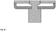
- the outer contact is made from a double or multiple layers in which one layer at least is made from a strong, elastic and conductive material like stainless steel, and at least a second layer made from high thermal conductivity material like copper.
- This combination offers both robustness and cost effectiveness criteria to the contact assembly and would guarantee a better thermal management during and after arcing (fast contacts cooling).
- the multi-layer cup-shaped contact may have several various arrangements on the superposition order of the layers depending on the intended application. For example for a double-layer:
- Figure 3a shows a double layer system with a stainless-steel inner layer and a copper outer layer.
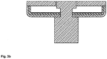
- Figure 3b shows a double layer system with a copper inner layer and a stainless steel outer layer.
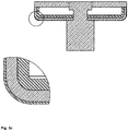
- Figure 3c shows a multilayer system with stainless steel inner layer, plus a copper outer layer with a thin coverage by steel/nickel layer.
- Figure 3d shows a multilayer system with a copper inner layer plus a stainless steel outer layer with a thin coverage by a thin copper layer.
Landscapes
- Contacts (AREA)
- High-Tension Arc-Extinguishing Switches Without Spraying Means (AREA)
Applications Claiming Priority (2)
| Application Number | Priority Date | Filing Date | Title |
|---|---|---|---|
| EP12004395 | 2012-06-11 | ||
| EP12007203.8A EP2674955B1 (en) | 2012-06-11 | 2012-10-18 | Vacuum interrupter with double coaxial contact arrangement at each side |
Related Parent Applications (2)
| Application Number | Title | Priority Date | Filing Date |
|---|---|---|---|
| EP12007203.8A Division-Into EP2674955B1 (en) | 2012-06-11 | 2012-10-18 | Vacuum interrupter with double coaxial contact arrangement at each side |
| EP12007203.8A Division EP2674955B1 (en) | 2012-06-11 | 2012-10-18 | Vacuum interrupter with double coaxial contact arrangement at each side |
Publications (1)
| Publication Number | Publication Date |
|---|---|
| EP3754684A1 true EP3754684A1 (en) | 2020-12-23 |
Family
ID=47044725
Family Applications (2)
| Application Number | Title | Priority Date | Filing Date |
|---|---|---|---|
| EP20189894.7A Pending EP3754684A1 (en) | 2012-06-11 | 2012-10-18 | Vacuum interrupter with double coaxial contact arrangement at each side |
| EP12007203.8A Active EP2674955B1 (en) | 2012-06-11 | 2012-10-18 | Vacuum interrupter with double coaxial contact arrangement at each side |
Family Applications After (1)
| Application Number | Title | Priority Date | Filing Date |
|---|---|---|---|
| EP12007203.8A Active EP2674955B1 (en) | 2012-06-11 | 2012-10-18 | Vacuum interrupter with double coaxial contact arrangement at each side |
Country Status (6)
| Country | Link |
|---|---|
| US (1) | US20150114931A1 (cg-RX-API-DMAC7.html) |
| EP (2) | EP3754684A1 (cg-RX-API-DMAC7.html) |
| JP (1) | JP2015519713A (cg-RX-API-DMAC7.html) |
| CN (1) | CN104488057A (cg-RX-API-DMAC7.html) |
| IN (1) | IN2014DN10567A (cg-RX-API-DMAC7.html) |
| WO (1) | WO2013185906A1 (cg-RX-API-DMAC7.html) |
Families Citing this family (1)
| Publication number | Priority date | Publication date | Assignee | Title |
|---|---|---|---|---|
| DE102020212377A1 (de) * | 2020-09-30 | 2022-03-31 | Siemens Aktiengesellschaft | Kompakte Vakuumschaltröhre |
Citations (5)
| Publication number | Priority date | Publication date | Assignee | Title |
|---|---|---|---|---|
| US3210505A (en) * | 1962-04-03 | 1965-10-05 | Gen Electric | Electrode structure for an electric circuit interrupter |
| DE9305125U1 (de) * | 1993-03-30 | 1994-08-04 | Siemens AG, 80333 München | Kontaktanordnung für eine Vakuumschaltröhre |
| EP0660353A2 (en) * | 1993-12-24 | 1995-06-28 | Hitachi, Ltd. | Vacuum valve and method of manufacturing the same |
| WO2003096364A1 (de) * | 2002-05-07 | 2003-11-20 | Siemens Aktiengesellschaft | Tropfförmiger schaltkontakt mit metalldampfabschirmung |
| EP2434513A1 (en) | 2010-09-24 | 2012-03-28 | ABB Technology AG | Electrical contact arrangement for vacuum interrupter arrangement |
Family Cites Families (8)
| Publication number | Priority date | Publication date | Assignee | Title |
|---|---|---|---|---|
| US3980850A (en) * | 1974-12-19 | 1976-09-14 | Westinghouse Electric Corporation | Vacuum interrupter with cup-shaped contact having an inner arc controlling electrode |
| JPS56138836A (en) * | 1980-03-31 | 1981-10-29 | Meidensha Electric Mfg Co Ltd | Vacuum breaker |
| JPS6065413A (ja) * | 1983-09-20 | 1985-04-15 | 株式会社東芝 | 真空遮断器 |
| US4847456A (en) * | 1987-09-23 | 1989-07-11 | Westinghouse Electric Corp. | Vacuum circuit interrupter with axial magnetic arc transfer mechanism |
| US6965089B2 (en) * | 2003-02-21 | 2005-11-15 | Mcgraw-Edison Company | Axial magnetic field vacuum fault interrupter |
| CN1981354B (zh) * | 2004-07-05 | 2011-10-26 | Abb研究有限公司 | 用于真空开关的真空开关室和接触件装置 |
| CN101164130A (zh) * | 2005-04-16 | 2008-04-16 | Abb技术股份公司 | 用于真空开关箱的接触件的制造方法 |
| DE102006042101B4 (de) * | 2006-09-07 | 2008-09-25 | Switchcraft Europe Gmbh | Vakuumschalter für Mittel- und Hochspannungen |
-
2012
- 2012-10-18 EP EP20189894.7A patent/EP3754684A1/en active Pending
- 2012-10-18 EP EP12007203.8A patent/EP2674955B1/en active Active
-
2013
- 2013-06-11 CN CN201380038542.1A patent/CN104488057A/zh active Pending
- 2013-06-11 IN IN10567DEN2014 patent/IN2014DN10567A/en unknown
- 2013-06-11 WO PCT/EP2013/001708 patent/WO2013185906A1/en not_active Ceased
- 2013-06-11 JP JP2015516506A patent/JP2015519713A/ja active Pending
-
2014
- 2014-12-11 US US14/567,489 patent/US20150114931A1/en not_active Abandoned
Patent Citations (5)
| Publication number | Priority date | Publication date | Assignee | Title |
|---|---|---|---|---|
| US3210505A (en) * | 1962-04-03 | 1965-10-05 | Gen Electric | Electrode structure for an electric circuit interrupter |
| DE9305125U1 (de) * | 1993-03-30 | 1994-08-04 | Siemens AG, 80333 München | Kontaktanordnung für eine Vakuumschaltröhre |
| EP0660353A2 (en) * | 1993-12-24 | 1995-06-28 | Hitachi, Ltd. | Vacuum valve and method of manufacturing the same |
| WO2003096364A1 (de) * | 2002-05-07 | 2003-11-20 | Siemens Aktiengesellschaft | Tropfförmiger schaltkontakt mit metalldampfabschirmung |
| EP2434513A1 (en) | 2010-09-24 | 2012-03-28 | ABB Technology AG | Electrical contact arrangement for vacuum interrupter arrangement |
Also Published As
| Publication number | Publication date |
|---|---|
| WO2013185906A1 (en) | 2013-12-19 |
| CN104488057A (zh) | 2015-04-01 |
| EP2674955B1 (en) | 2020-12-02 |
| EP2674955A1 (en) | 2013-12-18 |
| US20150114931A1 (en) | 2015-04-30 |
| IN2014DN10567A (cg-RX-API-DMAC7.html) | 2015-08-28 |
| JP2015519713A (ja) | 2015-07-09 |
Similar Documents
| Publication | Publication Date | Title |
|---|---|---|
| EP2434513B1 (en) | Electrical contact arrangement for vacuum interrupter arrangement | |
| EP2551878A1 (en) | Contact assembly for a vacuum circuit breaker | |
| JP2015525945A (ja) | 高速作動型回路遮断器を構成する電気スイッチ | |
| CN101459013B (zh) | 一种低回路电阻的纵向磁场电极的真空开关管 | |
| US9613769B2 (en) | Vacuum interrupter for a circuit breaker arrangement | |
| US4594489A (en) | Electrical switching element | |
| US20220013307A1 (en) | Dual parallel moveable electrical contacts/relays | |
| EP3360149A1 (en) | Switching device | |
| EP1149398B1 (en) | Vacuum switching device | |
| JP5274676B2 (ja) | 真空バルブ | |
| JP5019461B2 (ja) | 電気的スイッチング・デバイスのためのコンタクト・システム | |
| US20120312667A1 (en) | Power breaker | |
| US20240087822A1 (en) | Vacuum Interrupter | |
| EP2674955B1 (en) | Vacuum interrupter with double coaxial contact arrangement at each side | |
| CN102034640B (zh) | 具有并联额定电流路径的功率开关 | |
| JP5629589B2 (ja) | 開閉器 | |
| KR101015495B1 (ko) | 시퀀스 스위치용 부하시 탭 절환장치 | |
| JP3967387B2 (ja) | アーク切換開閉器 | |
| JP2018181681A (ja) | 補強リングおよび真空インタラプタ | |
| US3996438A (en) | Vacuum-type circuit interrupter with two sets of contacts electrically in parallel | |
| CN113178301A (zh) | 电磁致动器以及包括这种电磁致动器的电气开关单元 | |
| KR20160040585A (ko) | 전기 접점 및 접촉자 | |
| JP4684914B2 (ja) | 真空遮断器 | |
| JP2013004360A (ja) | ガス絶縁開閉装置用通電部材 | |
| JP2013115015A (ja) | ガス絶縁開閉機器 |
Legal Events
| Date | Code | Title | Description |
|---|---|---|---|
| PUAI | Public reference made under article 153(3) epc to a published international application that has entered the european phase |
Free format text: ORIGINAL CODE: 0009012 |
|
| STAA | Information on the status of an ep patent application or granted ep patent |
Free format text: STATUS: THE APPLICATION HAS BEEN PUBLISHED |
|
| AC | Divisional application: reference to earlier application |
Ref document number: 2674955 Country of ref document: EP Kind code of ref document: P |
|
| AK | Designated contracting states |
Kind code of ref document: A1 Designated state(s): AL AT BE BG CH CY CZ DE DK EE ES FI FR GB GR HR HU IE IS IT LI LT LU LV MC MK MT NL NO PL PT RO RS SE SI SK SM TR |
|
| STAA | Information on the status of an ep patent application or granted ep patent |
Free format text: STATUS: REQUEST FOR EXAMINATION WAS MADE |
|
| 17P | Request for examination filed |
Effective date: 20210510 |
|
| RBV | Designated contracting states (corrected) |
Designated state(s): AL AT BE BG CH CY CZ DE DK EE ES FI FR GB GR HR HU IE IS IT LI LT LU LV MC MK MT NL NO PL PT RO RS SE SI SK SM TR |
|
| STAA | Information on the status of an ep patent application or granted ep patent |
Free format text: STATUS: EXAMINATION IS IN PROGRESS |
|
| 17Q | First examination report despatched |
Effective date: 20221123 |