EP3754675A1 - Wireless power transmission system comprising transparent heating element, and head mounted device including same - Google Patents
Wireless power transmission system comprising transparent heating element, and head mounted device including same Download PDFInfo
- Publication number
- EP3754675A1 EP3754675A1 EP18905826.6A EP18905826A EP3754675A1 EP 3754675 A1 EP3754675 A1 EP 3754675A1 EP 18905826 A EP18905826 A EP 18905826A EP 3754675 A1 EP3754675 A1 EP 3754675A1
- Authority
- EP
- European Patent Office
- Prior art keywords
- bus bar
- transmission system
- power transmission
- wireless power
- base substrate
- Prior art date
- Legal status (The legal status is an assumption and is not a legal conclusion. Google has not performed a legal analysis and makes no representation as to the accuracy of the status listed.)
- Granted
Links
Images


Classifications
-
- A—HUMAN NECESSITIES
- A42—HEADWEAR
- A42B—HATS; HEAD COVERINGS
- A42B3/00—Helmets; Helmet covers ; Other protective head coverings
- A42B3/04—Parts, details or accessories of helmets
- A42B3/18—Face protection devices
- A42B3/22—Visors
- A42B3/24—Visors with means for avoiding fogging or misting
- A42B3/245—Visors with means for avoiding fogging or misting using means for heating, e.g. electric heating of the visor
-
- G—PHYSICS
- G01—MEASURING; TESTING
- G01D—MEASURING NOT SPECIALLY ADAPTED FOR A SPECIFIC VARIABLE; ARRANGEMENTS FOR MEASURING TWO OR MORE VARIABLES NOT COVERED IN A SINGLE OTHER SUBCLASS; TARIFF METERING APPARATUS; MEASURING OR TESTING NOT OTHERWISE PROVIDED FOR
- G01D21/00—Measuring or testing not otherwise provided for
- G01D21/02—Measuring two or more variables by means not covered by a single other subclass
-
- G—PHYSICS
- G02—OPTICS
- G02B—OPTICAL ELEMENTS, SYSTEMS OR APPARATUS
- G02B27/00—Optical systems or apparatus not provided for by any of the groups G02B1/00 - G02B26/00, G02B30/00
- G02B27/0006—Optical systems or apparatus not provided for by any of the groups G02B1/00 - G02B26/00, G02B30/00 with means to keep optical surfaces clean, e.g. by preventing or removing dirt, stains, contamination, condensation
-
- H—ELECTRICITY
- H01—ELECTRIC ELEMENTS
- H01F—MAGNETS; INDUCTANCES; TRANSFORMERS; SELECTION OF MATERIALS FOR THEIR MAGNETIC PROPERTIES
- H01F27/00—Details of transformers or inductances, in general
- H01F27/08—Cooling; Ventilating
- H01F27/22—Cooling by heat conduction through solid or powdered fillings
-
- H—ELECTRICITY
- H01—ELECTRIC ELEMENTS
- H01F—MAGNETS; INDUCTANCES; TRANSFORMERS; SELECTION OF MATERIALS FOR THEIR MAGNETIC PROPERTIES
- H01F27/00—Details of transformers or inductances, in general
- H01F27/28—Coils; Windings; Conductive connections
- H01F27/2804—Printed windings
-
- H—ELECTRICITY
- H01—ELECTRIC ELEMENTS
- H01F—MAGNETS; INDUCTANCES; TRANSFORMERS; SELECTION OF MATERIALS FOR THEIR MAGNETIC PROPERTIES
- H01F27/00—Details of transformers or inductances, in general
- H01F27/28—Coils; Windings; Conductive connections
- H01F27/2823—Wires
- H01F27/2828—Construction of conductive connections, of leads
-
- H—ELECTRICITY
- H01—ELECTRIC ELEMENTS
- H01F—MAGNETS; INDUCTANCES; TRANSFORMERS; SELECTION OF MATERIALS FOR THEIR MAGNETIC PROPERTIES
- H01F27/00—Details of transformers or inductances, in general
- H01F27/28—Coils; Windings; Conductive connections
- H01F27/32—Insulating of coils, windings, or parts thereof
- H01F27/324—Insulation between coil and core, between different winding sections, around the coil; Other insulation structures
-
- H—ELECTRICITY
- H01—ELECTRIC ELEMENTS
- H01F—MAGNETS; INDUCTANCES; TRANSFORMERS; SELECTION OF MATERIALS FOR THEIR MAGNETIC PROPERTIES
- H01F38/00—Adaptations of transformers or inductances for specific applications or functions
- H01F38/14—Inductive couplings
-
- H—ELECTRICITY
- H02—GENERATION; CONVERSION OR DISTRIBUTION OF ELECTRIC POWER
- H02J—ELECTRIC POWER NETWORKS; CIRCUIT ARRANGEMENTS OR SYSTEMS FOR SUPPLYING OR DISTRIBUTING ELECTRIC POWER; SYSTEMS FOR STORING ELECTRIC ENERGY
- H02J50/00—Circuit arrangements or systems for wireless supply or distribution of electric power
- H02J50/005—Mechanical details of housing or structure aiming to accommodate the power transfer means, e.g. mechanical integration of coils, antennas or transducers into emitting or receiving devices
-
- H—ELECTRICITY
- H02—GENERATION; CONVERSION OR DISTRIBUTION OF ELECTRIC POWER
- H02J—ELECTRIC POWER NETWORKS; CIRCUIT ARRANGEMENTS OR SYSTEMS FOR SUPPLYING OR DISTRIBUTING ELECTRIC POWER; SYSTEMS FOR STORING ELECTRIC ENERGY
- H02J50/00—Circuit arrangements or systems for wireless supply or distribution of electric power
- H02J50/10—Circuit arrangements or systems for wireless supply or distribution of electric power using inductive coupling
-
- H—ELECTRICITY
- H02—GENERATION; CONVERSION OR DISTRIBUTION OF ELECTRIC POWER
- H02J—ELECTRIC POWER NETWORKS; CIRCUIT ARRANGEMENTS OR SYSTEMS FOR SUPPLYING OR DISTRIBUTING ELECTRIC POWER; SYSTEMS FOR STORING ELECTRIC ENERGY
- H02J7/00—Circuit arrangements for charging or discharging batteries or for supplying loads from batteries
- H02J7/02—Circuit arrangements for charging or discharging batteries or for supplying loads from batteries for charging batteries from AC mains by converters
-
- H—ELECTRICITY
- H05—ELECTRIC TECHNIQUES NOT OTHERWISE PROVIDED FOR
- H05B—ELECTRIC HEATING; ELECTRIC LIGHT SOURCES NOT OTHERWISE PROVIDED FOR; CIRCUIT ARRANGEMENTS FOR ELECTRIC LIGHT SOURCES, IN GENERAL
- H05B3/00—Ohmic-resistance heating
- H05B3/84—Heating arrangements specially adapted for transparent or reflecting areas, e.g. for demisting or de-icing windows, mirrors or vehicle windshields
-
- H—ELECTRICITY
- H05—ELECTRIC TECHNIQUES NOT OTHERWISE PROVIDED FOR
- H05B—ELECTRIC HEATING; ELECTRIC LIGHT SOURCES NOT OTHERWISE PROVIDED FOR; CIRCUIT ARRANGEMENTS FOR ELECTRIC LIGHT SOURCES, IN GENERAL
- H05B6/00—Heating by electric, magnetic or electromagnetic fields
- H05B6/02—Induction heating
- H05B6/10—Induction heating apparatus, other than furnaces, for specific applications
-
- H—ELECTRICITY
- H05—ELECTRIC TECHNIQUES NOT OTHERWISE PROVIDED FOR
- H05B—ELECTRIC HEATING; ELECTRIC LIGHT SOURCES NOT OTHERWISE PROVIDED FOR; CIRCUIT ARRANGEMENTS FOR ELECTRIC LIGHT SOURCES, IN GENERAL
- H05B6/00—Heating by electric, magnetic or electromagnetic fields
- H05B6/02—Induction heating
- H05B6/36—Coil arrangements
-
- H—ELECTRICITY
- H05—ELECTRIC TECHNIQUES NOT OTHERWISE PROVIDED FOR
- H05B—ELECTRIC HEATING; ELECTRIC LIGHT SOURCES NOT OTHERWISE PROVIDED FOR; CIRCUIT ARRANGEMENTS FOR ELECTRIC LIGHT SOURCES, IN GENERAL
- H05B2203/00—Aspects relating to Ohmic resistive heating covered by group H05B3/00
- H05B2203/011—Heaters using laterally extending conductive material as connecting means
-
- H—ELECTRICITY
- H05—ELECTRIC TECHNIQUES NOT OTHERWISE PROVIDED FOR
- H05B—ELECTRIC HEATING; ELECTRIC LIGHT SOURCES NOT OTHERWISE PROVIDED FOR; CIRCUIT ARRANGEMENTS FOR ELECTRIC LIGHT SOURCES, IN GENERAL
- H05B2203/00—Aspects relating to Ohmic resistive heating covered by group H05B3/00
- H05B2203/013—Heaters using resistive films or coatings
Definitions
- the present invention relates to a wireless power transmission system including a transparent heat generating element and a head mount device having the same.
- Wireless power transmission or wireless energy transfer technology that wirelessly transmits electric energy to a desired device has already begun to use in electric motors or transformers using the electromagnetic induction principle since 1800s. After then, methods of transmitting electrical energy by radiating electromagnetic waves such as radio waves or lasers have also been attempted. Electric toothbrushes and some wireless shavers, which are commonly used, are actually charged using the electromagnetic induction principle. To date, energy transfer methods using the wireless system includes magnetic induction, magnetic resonance, and long-distance transmission technology using short-wavelength radio frequencies.
- a viewing part made of a transparent material and disposed in a front side thereof can be filled with moisture due to user's breathing, ambient temperature, or ambient humidity, etc., which prevents the user's view.
- An object of the present invention is to provide a head mount device including a wireless power transmission system that helps secure a user's view by using a wireless power transmission technology.
- a wireless power transmission system includes a power receiving module and a power transmitting module.
- the power receiving module may include a base substrate, a humidity sensor on the base substrate, a plurality of transparent heat generating elements on the base substrate, a first bus bar disposed on the base substrate and electrically connected to at least some of the plurality of transparent heat generating elements, a second bus bar disposed on the base substrate to be spaced apart from the first bus bar and electrically connected to at least some of the plurality of transparent heat generating elements, and a first coil pattern electrically connected to the first bus bar and the second bus bar.
- the power transmitting module may include a battery, a control circuit capable of controlling the battery and the humidity sensor, and a second coil pattern electrically connected to the control circuit and transmitting the power supplied from the battery to the first coil pattern in an electromagnetic inductive coupling method.
- a head mount device may include a frame part accommodating a user's head and a viewing part disposed at a position corresponding to user's eyes to allow the user to see outside.
- the viewing part may include a base substrate, a humidity sensor on the base substrate, a plurality of transparent heat generating elements on the base substrate, a first bus bar disposed on the base substrate and electrically connected to at least some of the plurality of transparent heat generating elements, a second bus bar disposed on the base substrate to be spaced apart from the first bus bar and electrically connected to at least some of the plurality of transparent heat generating elements, and a first coil pattern electrically connected to the first bus bar and the second bus bar.
- the frame part may include a battery, a control circuit capable of controlling the battery and the humidity sensor, and a second coil pattern electrically connected to the control circuit and transmitting the power supplied from the battery to the first coil pattern in an electromagnetic inductive coupling method.
- a head mount device including a wireless power transmission system capable of wirelessly providing power based on a measured ambient humidity to a transparent heat generating element.
- FIG. 1 and FIG. 2 are diagrams illustrating wireless power transmission systems WPT and WPT-1 according to an embodiment of the present invention.
- a wireless power transmission system WPT may include a power receiving module RU and a power transmitting module TU.
- the power receiving module RU may include a base substrate BS, a plurality of transparent heat generating elements TL, a first bus bar BB1, a second bus bar BB2, a first coil pattern L1, a first insulating part ISP1, and sensors SS1 and SS2.
- the base substrate BS may include a flexible film, glass, or plastic. Any material included in the base substrate BS may be sufficient as long as the plurality of transparent heat generating elements TL, the first bus bar BB1, and the second bus bar BB2 can be disposed. However, it is not limited thereto.
- the base substrate BS may have transparent properties. Accordingly, the base substrate BS may be able to transmit light incident from the outside.
- the transparent heat generating element TL may be disposed on the base substrate BS.
- the transparent heat generating element TL may be silver nanowire (AgNW), indium zinc oxide (IZO), or indium tin oxide (ITO).
- the transparent heat generating element TL may include a commonly used transparent heat generating element material or transparent electrode material. However, it is not limited thereto.
- At least some of the transparent heat generating elements TL may be electrically connected to other adjacent transparent heat generating elements.
- the first bus bar BB1 and the second bus bar BB2 may be disposed on the base substrate BS. Each of the first bus bar BB1 and the second bus bar BB2 may be electrically connected to at least some of the transparent heat generating elements TL.
- the first bus bar BB1 and the second bus bar BB2 may be spaced apart from each other.
- the second bus bar BB2 may be electrically connected to the first bus bar BB1 through the transparent heat generating elements TL.
- the first bus bar BB1 and the second bus bar BB2 may be printed circuit boards.
- conductive patterns disposed on each one surface of the first bus bar BB1 and the second bus bar BB2 may be electrically connected to the transparent heat generating elements TL.
- the first bus bar BB1 and the second bus bar BB2 may be silver nano paste.
- the first bus bar BB1 and the second bus bar BB2 may be any conductive material including copper (Cu).
- the first bus bar BB1 and the second bus bar BB2 may include various materials capable of transmitting power provided from the outside to the transparent heat generating elements TL. However, it is not limited thereto.
- the first coil pattern L1 may be electrically connected to the first bus bar BB1 and the second bus bar BB2.
- the first coil pattern L1 may be, for example, an inductor.
- the first coil pattern L1 may receive power provided from the outside by an electromagnetic inductive coupling method.
- the first coil pattern L1 may be arranged on the printed circuit board extending from the first bus bar BB1 or the second bus bar BB2.
- the first coil pattern L1 is formed by patterning a printed circuit board in a flat shape, there may be an advantage that the bus bars BB1 and BB2 and the first coil pattern L1 can be manufactured at once.
- the first insulating part ISP1 may cover the first coil pattern L1 to insulate the first coil pattern L1 from the power transmitting module TU.
- the first insulating part ISP1 may be resin, silicone, or polymer, but is not limited thereto.
- the sensors SS1 and SS2 may be disposed on the base substrate BS.
- the humidity sensor SS1 may measure an ambient humidity.
- the humidity sensor SS1 may determine whether moisture or fog is generated in the base substrate BS.
- the temperature sensor SS2 may measure an ambient temperature.
- the temperature sensor SS2 may be determine a temperature of the base substrate BS before being heated by the transparent heat generating elements TL or a temperature of the base substrate BS after being heated by the transparent heat generating elements TL.
- the humidity sensor SS1 and the temperature sensor SS2 may be disposed adjacent to the first bus bar BB1 or the second bus bar BB2.
- the humidity sensor SS1 and the temperature sensor SS2 unlike the transparent heat generating elements TL, may be well recognized by the human eye. Therefore, when the humidity sensor SS1 and the temperature sensor SS2 are disposed adjacent to the first bus bar BB1 or the second bus bar BB2, it may prevent the humidity sensor SS1 and the temperature sensor SS2 from being viewed even when the wireless power transmission system WPT according to an embodiment of the present invention is applied to a head mound device or the like.
- the power transmitting module TU may include a battery BT, a control circuit CC, a second coil pattern L2, and a second insulating part ISP2.
- the battery BT may provide power to the control circuit CC and the like.
- the control circuit CC may be electrically connected to the battery BT and the sensors SS1 and SS2. Accordingly, the control circuit CC may be able to control the battery BT and the sensors SS1 and SS2 and may exchange power with them.
- the control circuit CC may exchange signals with the sensors SS1 and SS2 by wire or wirelessly.
- the second coil pattern L2 may be electrically connected to the control circuit CC.
- the second coil pattern L2 may be, for example, an inductor.
- the second coil pattern L2 may transmit power supplied from the battery BT to the first coil pattern L1 in an electromagnetic inductive coupling method.
- the second insulating part ISP2 may cover the second coil pattern L2 to insulate the second coil pattern L2 from the first coil pattern L1.
- the second insulating part ISP2 may be resin, silicone, or polymer, but it is not limited thereto.
- the first coil pattern L1 and the second coil pattern L2 are covered by the first insulating part ISP1 and the second insulating part ISP2, respectively, even if the distance between the first coil pattern L1 and the second coil pattern L2 is close each other, the first coil pattern L1 and the second coil pattern L2 may not be shorted to each other. Thus, the distance between the first coil pattern L1 and the second coil pattern L2 may be made close, and, accordingly, power may be efficiency transferred from the second coil pattern L2 to the first coil pattern L1.
- a wireless power transmission system WPT-1 may include a power receiving module RU-1 and a power transmitting module TU-1.
- the humidity sensor SS1 may be included in the power transmitting module TU-1, not in the power receiving module RU-1.
- FIG. 3 is a diagram illustrating a battery BT and a wireless charging module WCM according to an embodiment of the present invention.
- the battery BT included in the power transmitting module (TU, TU-1, see FIGS. 1 and 2 ) may be charged by receiving wireless power from the wireless charging module WCM.
- the battery BT may include a third coil pattern L3 and the wireless charging module WCM may include a fourth coil pattern L4. Accordingly, the third coil pattern L3 may receive power in an electromagnetic inductive coupling method from the fourth coil pattern L4.
- Various techniques for charging an existing battery wirelessly may be applied. However, it is not limited thereto.
- FIG. 4A , FIG. 4B, FIG. 4C, and FIG. 4D are diagrams illustrating cross-sectional views taken along line I-I' in FIG. 1 , respectively.
- the first bus bar BB1 may be mounted directly on the base substrate BS to be electrically connected to the transparent heat generating elements TL.
- the second bus bar BB2 may also be mounted on the base substrate BS in the same manner as the first bus bar BB1.
- the first bus bar BB1 may be mounted on the base substrate BS by a conductive adhesive member ADH to be electrically connected to the transparent heat generating elements TL.
- the second bus bar BB2 may also be mounted on the base substrate BS in the same manner as the first bus bar BB1.
- the conductive adhesive member ADH may be an adhesive including silver (Ag), such as an anisotropic conductive film (ACF) and Ag adhesive, or any conductive material.
- a conductive line ML for adhesion may be added to the diagram of FIG. 4B .
- the conductive line ML may include a metal material capable of transmitting an electrical signal.
- the first bus bar BB1 may be electrically connected to the transparent heat generating elements TL by the conductive adhesive member ADH and the conductive line ML for adhesion.
- the second bus bar BB2 may also be disposed on the base substrate BS in the same manner as the first bus bar BB1.
- a concave groove HM may be defined in the base substrate BS.
- the first bus bar BB1 may be disposed to correspond to the groove HM to be electrically connected to the transparent heat generating elements TL.
- the second bus bar BB2 may also be disposed on the base substrate BS in the same manner as the first bus bar BB1.
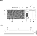
- FIG. 5A is a diagram illustrating a wireless power transmission system WPT-2 according to an embodiment of the present invention.
- FIG. 5B is a diagram illustrating a cross-sectional view taken along line II-II' in FIG. 5A .
- a first bus bar BB1 may be covered by a first sealing member EC1 and a second bus bar BB2 may be covered by a second sealing member EC2. Accordingly, as the bus bars BB1 and BB2 are sealed by the sealing members EC1 and EC2, the bus bars BB1 and BB2 may be protected from external moisture. In addition, generation of sparks may be prevented in the bus bars BB1 and BB2.
- FIG. 6A is a diagram illustrating a wireless power transmission system WPT-3 according to an embodiment of the present invention.
- FIG. 6B is a diagram illustrating a cross-sectional view taken along line II-II' in FIG. 5C .
- a base substrate BS, bus bars BB1 and BB2, and transparent heat generating elements TL may be entirely covered and sealed by a sealing member EC.
- the sealing member EC may be disposed on a front surface and/or a back surface of the base substrate BS.
- FIG. 7A , FIG. 7B , and FIG. 7C are flowcharts illustrating a process of operating a wireless power transmission system WPT, WPT-1, WPT-2, WPT-3 according to an embodiment of the present invention.
- a humidity sensor SS1 may measure an ambient relative humidity at a predetermined time interval (S10).
- the predetermined time interval may be, for example, 1 to 10 seconds.
- a control circuit CC may determine whether the relative humidity measured by the humidity sensor SS1 is greater than or equal to a predetermined humidity value (S20).
- the predetermined humidity value may be, for example, 50% to 70%.
- a power transmitting module TU may wirelessly transmit power to a power receiving module RU (S30).
- the power transmitting module TU does not wirelessly transmit power to the power receiving module RU (S40).
- the power may be transmitted wirelessly in advance to increase the temperature of the transparent heat generating elements TL of the power receiving module RU, thereby preventing the base substrate BS from being moisturized or fogged or eliminating moisture or fog quickly even if moisture or fog is generated. This may be defined as pre-heating.
- a temperature sensor SS2 may measure such a temperature change (S50).
- the control circuit CC may determine whether the temperature measured by the temperature sensor SS2 is equal to or higher than a predetermined temperature value (S60).
- the predetermined temperature value may be a fixed specific value.
- the predetermined temperature value may be a value that is about 4°C to 10°C greater than the temperature at which the power transmitting module TU starts transmitting power to the power receiving module RU..
- the power transmitting module TU may stop transmitting wireless power to the power receiving module RU (S70).
- the power transmitting module TU may continuously transmit wireless power to the power receiving module RU (S80).
- the predetermined temperature value may be 40°C or less.
- the temperature of the transparent heat generating elements TL is greater than 40°C, a user who uses it may feel discomfort or may be burned at a temperature higher than his/her body temperature.
- subsequent steps S90 to S110 may have been added from the steps of FIG. 7A .
- the power transmitting module TU may transmit a second power to the power receiving module RU. (S100).
- the power transmitting module TU may transmit a first power having a value less than the second power to the power receiving module RU.
- FIG. 8 is a diagram illustrating a head mount device HMD to which the wireless power transmission system WPT shown in FIG. 1 is applied.
- FIG. 9 is a diagram illustrating that the head mount device HMD shown in FIG. 8 is mounted.
- the head mount device HMD may include a frame part FRM and a viewing part VP.
- the frame FRM may accommodate a user's head, allowing the user to secure the head mount device HMD to the user's head.
- the sensor SS may include a humidity sensor SS1 and/or a temperature sensor SS2 and may be disposed on the viewing part VP.
- the frame part FRM may include a front part FF facing a user's face, a rear part RR facing a user's back head, and an upper part HH facing a user's head.
- the upper part HH may connect the front part FF and the rear part RR.
- the viewing part VP may include the power receiving module RU of the wireless power transmission system WPT illustrated in FIG. 1 .
- the viewing part VP may be implemented by attaching the power receiving module RU having a flexible property to a glass or transparent plastic substrate.
- the viewing part VP may be implemented as the power receiving module RU itself having a rigid property.
- the frame part FRM may include a power transmitting module TU.
- the power transmitting module TU is disposed on the upper part HH of the frame part FRM, but is not limited thereto.
- the position in which the power transmitting module TU is disposed may be changed as necessary.
- the battery BT may be charged by receiving wireless power by the wireless charging module WCM-1.
- the battery BT may be disposed on the upper part HH where the head mount device HMD comes into contact with the wireless charging module WCM-1 and, thus, may be easily and wirelessly supplied with power.
- the position where the battery BT is disposed may be changed.
- the present invention relating to a technology for removing fog or moisture formed in the surface of a transparent object has high industrial applicability.
Landscapes
- Engineering & Computer Science (AREA)
- Power Engineering (AREA)
- Physics & Mathematics (AREA)
- Electromagnetism (AREA)
- Computer Networks & Wireless Communication (AREA)
- General Physics & Mathematics (AREA)
- Optics & Photonics (AREA)
- Charge And Discharge Circuits For Batteries Or The Like (AREA)
Abstract
Description
- The present invention relates to a wireless power transmission system including a transparent heat generating element and a head mount device having the same.
- Wireless power transmission or wireless energy transfer technology that wirelessly transmits electric energy to a desired device has already begun to use in electric motors or transformers using the electromagnetic induction principle since 1800s. After then, methods of transmitting electrical energy by radiating electromagnetic waves such as radio waves or lasers have also been attempted. Electric toothbrushes and some wireless shavers, which are commonly used, are actually charged using the electromagnetic induction principle. To date, energy transfer methods using the wireless system includes magnetic induction, magnetic resonance, and long-distance transmission technology using short-wavelength radio frequencies.
- On the other hand, when a helmet, a gas mask, or a fire mask is used, a viewing part made of a transparent material and disposed in a front side thereof can be filled with moisture due to user's breathing, ambient temperature, or ambient humidity, etc., which prevents the user's view.
- This Summary is provided to introduce a selection of concepts in a simplified form that are further described below in the Detailed Description. This Summary is not intended to identify key features or essential features of the claimed subject matter, nor is it intended to be used as an aid in determining the scope of the claimed subject matter.
- An object of the present invention is to provide a head mount device including a wireless power transmission system that helps secure a user's view by using a wireless power transmission technology.
- A wireless power transmission system according to an embodiment of the present invention includes a power receiving module and a power transmitting module.
- The power receiving module may include a base substrate, a humidity sensor on the base substrate, a plurality of transparent heat generating elements on the base substrate, a first bus bar disposed on the base substrate and electrically connected to at least some of the plurality of transparent heat generating elements, a second bus bar disposed on the base substrate to be spaced apart from the first bus bar and electrically connected to at least some of the plurality of transparent heat generating elements, and a first coil pattern electrically connected to the first bus bar and the second bus bar.
- The power transmitting module may include a battery, a control circuit capable of controlling the battery and the humidity sensor, and a second coil pattern electrically connected to the control circuit and transmitting the power supplied from the battery to the first coil pattern in an electromagnetic inductive coupling method.
- A head mount device according to an embodiment of the present invention may include a frame part accommodating a user's head and a viewing part disposed at a position corresponding to user's eyes to allow the user to see outside.
- The viewing part may include a base substrate, a humidity sensor on the base substrate, a plurality of transparent heat generating elements on the base substrate, a first bus bar disposed on the base substrate and electrically connected to at least some of the plurality of transparent heat generating elements, a second bus bar disposed on the base substrate to be spaced apart from the first bus bar and electrically connected to at least some of the plurality of transparent heat generating elements, and a first coil pattern electrically connected to the first bus bar and the second bus bar.
- The frame part may include a battery, a control circuit capable of controlling the battery and the humidity sensor, and a second coil pattern electrically connected to the control circuit and transmitting the power supplied from the battery to the first coil pattern in an electromagnetic inductive coupling method.
- According to an embodiment of the present invention, there is provided a head mount device including a wireless power transmission system capable of wirelessly providing power based on a measured ambient humidity to a transparent heat generating element.
- Accordingly, generation of moisture may be prevented in a part of the wireless power transmission system and the head-mounted device and even if moisture is generated, the generated moisture may be quickly removed.
-
-
FIG. 1 andFIG. 2 are diagrams illustrating wireless power transmission systems according to an embodiment of the present invention. -
FIG. 3 is a diagram illustrating a battery and a wireless charging module according to an embodiment of the present invention. -
FIG. 4A ,FIG. 4B, FIG. 4C, and FIG. 4D are diagrams illustrating cross-sectional views taken along line I-I' inFIG. 1 , respectively. -
FIG. 5A is a diagram illustrating a wireless power transmission system according to an embodiment of the present invention. -
FIG. 5B is a diagram illustrating a cross-sectional view taken along line II-II' inFIG. 5A . -
FIG. 6A is a diagram illustrating a wireless power transmission system according to an embodiment of the present invention. -
FIG. 6B is a diagram illustrating a cross-sectional view taken along line II-II' inFIG. 5C . -
FIG. 7A ,FIG. 7B , andFIG. 7C are flowcharts illustrating a process of operating a wireless power transmission system according to an embodiment of the present invention. -
FIG. 8 is a diagram illustrating a head mount device to which the wireless power transmission system shown inFIG. 1 is applied. -
FIG. 9 is a diagram illustrating that the head mount device shown inFIG. 8 is mounted. - The following detailed description is provided to assist the reader in gaining a comprehensive understanding of the methods, apparatuses, and/or systems described herein. However, various changes, modifications, and equivalents of the methods, apparatuses, and/or systems described herein will be apparent to one of ordinary skill in the art. The sequences of operations described herein are merely examples, and are not limited to those set forth herein, but may be changed as will be apparent to one of ordinary skill in the art, with the exception of operations necessarily occurring in a certain order. Also, descriptions of functions and constructions that are well known to one of ordinary skill in the art may be omitted for increased clarity and conciseness.
- The terms used in the description are intended to describe certain embodiments only, and shall by no means restrict the present disclosure. Unless clearly used otherwise, expressions in the singular number include a plural meaning. In the present description, an expression such as "comprising" or "consisting of" is intended to designate a characteristic, a number, a step, an operation, an element, a part or combinations thereof, and shall not be construed to preclude any presence or possibility of one or more other characteristics, numbers, steps, operations, elements, parts or combinations thereof.
- In the drawings, the proportion and dimensions of components are exaggerated for effective description of technical content. The term of "and/or" includes all combinations of one or more that the associated configurations may define.
- Embodiments of the disclosure will be described below in more detail with reference to the accompanying drawings, in which those components are rendered the same reference number that are the same or are in correspondence, regardless of the figure number, and redundant explanations are omitted.
-
FIG. 1 andFIG. 2 are diagrams illustrating wireless power transmission systems WPT and WPT-1 according to an embodiment of the present invention. - Referring to
FIG. 1 , a wireless power transmission system WPT may include a power receiving module RU and a power transmitting module TU. - The power receiving module RU may include a base substrate BS, a plurality of transparent heat generating elements TL, a first bus bar BB1, a second bus bar BB2, a first coil pattern L1, a first insulating part ISP1, and sensors SS1 and SS2.
- The base substrate BS may include a flexible film, glass, or plastic. Any material included in the base substrate BS may be sufficient as long as the plurality of transparent heat generating elements TL, the first bus bar BB1, and the second bus bar BB2 can be disposed. However, it is not limited thereto.
- The base substrate BS may have transparent properties. Accordingly, the base substrate BS may be able to transmit light incident from the outside.
- The transparent heat generating element TL may be disposed on the base substrate BS. The transparent heat generating element TL may be silver nanowire (AgNW), indium zinc oxide (IZO), or indium tin oxide (ITO). The transparent heat generating element TL may include a commonly used transparent heat generating element material or transparent electrode material. However, it is not limited thereto.
- At least some of the transparent heat generating elements TL may be electrically connected to other adjacent transparent heat generating elements.
- The first bus bar BB1 and the second bus bar BB2 may be disposed on the base substrate BS. Each of the first bus bar BB1 and the second bus bar BB2 may be electrically connected to at least some of the transparent heat generating elements TL.
- The first bus bar BB1 and the second bus bar BB2 may be spaced apart from each other. The second bus bar BB2 may be electrically connected to the first bus bar BB1 through the transparent heat generating elements TL.
- In one embodiment of the present invention, the first bus bar BB1 and the second bus bar BB2 may be printed circuit boards. In this case, conductive patterns disposed on each one surface of the first bus bar BB1 and the second bus bar BB2 may be electrically connected to the transparent heat generating elements TL.
- In one embodiment of the present invention, the first bus bar BB1 and the second bus bar BB2 may be silver nano paste.
- In an embodiment of the present invention, the first bus bar BB1 and the second bus bar BB2 may be any conductive material including copper (Cu).
- The first bus bar BB1 and the second bus bar BB2 may include various materials capable of transmitting power provided from the outside to the transparent heat generating elements TL. However, it is not limited thereto.
- The first coil pattern L1 may be electrically connected to the first bus bar BB1 and the second bus bar BB2. The first coil pattern L1 may be, for example, an inductor. The first coil pattern L1 may receive power provided from the outside by an electromagnetic inductive coupling method.
- In one embodiment of the present invention, when the first bus bar BB1 and the second bus bar BB2 are respectively printed circuit boards, the first coil pattern L1 may be arranged on the printed circuit board extending from the first bus bar BB1 or the second bus bar BB2. When the first coil pattern L1 is formed by patterning a printed circuit board in a flat shape, there may be an advantage that the bus bars BB1 and BB2 and the first coil pattern L1 can be manufactured at once.
- The first insulating part ISP1 may cover the first coil pattern L1 to insulate the first coil pattern L1 from the power transmitting module TU. In one embodiment of the present invention, the first insulating part ISP1 may be resin, silicone, or polymer, but is not limited thereto.
- The sensors SS1 and SS2 may be disposed on the base substrate BS.
- The humidity sensor SS1 may measure an ambient humidity. The humidity sensor SS1 may determine whether moisture or fog is generated in the base substrate BS.
- The temperature sensor SS2 may measure an ambient temperature. The temperature sensor SS2 may be determine a temperature of the base substrate BS before being heated by the transparent heat generating elements TL or a temperature of the base substrate BS after being heated by the transparent heat generating elements TL.
- The humidity sensor SS1 and the temperature sensor SS2 may be disposed adjacent to the first bus bar BB1 or the second bus bar BB2. The humidity sensor SS1 and the temperature sensor SS2, unlike the transparent heat generating elements TL, may be well recognized by the human eye. Therefore, when the humidity sensor SS1 and the temperature sensor SS2 are disposed adjacent to the first bus bar BB1 or the second bus bar BB2, it may prevent the humidity sensor SS1 and the temperature sensor SS2 from being viewed even when the wireless power transmission system WPT according to an embodiment of the present invention is applied to a head mound device or the like.
- The power transmitting module TU may include a battery BT, a control circuit CC, a second coil pattern L2, and a second insulating part ISP2.
- The battery BT may provide power to the control circuit CC and the like.
- The control circuit CC may be electrically connected to the battery BT and the sensors SS1 and SS2. Accordingly, the control circuit CC may be able to control the battery BT and the sensors SS1 and SS2 and may exchange power with them.
- The control circuit CC may exchange signals with the sensors SS1 and SS2 by wire or wirelessly.
- The second coil pattern L2 may be electrically connected to the control circuit CC. The second coil pattern L2 may be, for example, an inductor. The second coil pattern L2 may transmit power supplied from the battery BT to the first coil pattern L1 in an electromagnetic inductive coupling method.
- The second insulating part ISP2 may cover the second coil pattern L2 to insulate the second coil pattern L2 from the first coil pattern L1. In one embodiment of the present invention, the second insulating part ISP2 may be resin, silicone, or polymer, but it is not limited thereto.
- As the first coil pattern L1 and the second coil pattern L2 are covered by the first insulating part ISP1 and the second insulating part ISP2, respectively, even if the distance between the first coil pattern L1 and the second coil pattern L2 is close each other, the first coil pattern L1 and the second coil pattern L2 may not be shorted to each other. Thus, the distance between the first coil pattern L1 and the second coil pattern L2 may be made close, and, accordingly, power may be efficiency transferred from the second coil pattern L2 to the first coil pattern L1.
- Referring to
FIG. 2 , a wireless power transmission system WPT-1 may include a power receiving module RU-1 and a power transmitting module TU-1. - In the wireless power transmission system WPT-1 shown in
FIG. 2 , unlikeFIG. 1 , the humidity sensor SS1 may be included in the power transmitting module TU-1, not in the power receiving module RU-1. - Descriptions of other components are substantially the same as those described in
FIG. 1 and thus are omitted. -
FIG. 3 is a diagram illustrating a battery BT and a wireless charging module WCM according to an embodiment of the present invention. - The battery BT included in the power transmitting module (TU, TU-1, see
FIGS. 1 and2 ) may be charged by receiving wireless power from the wireless charging module WCM. - For example, the battery BT may include a third coil pattern L3 and the wireless charging module WCM may include a fourth coil pattern L4. Accordingly, the third coil pattern L3 may receive power in an electromagnetic inductive coupling method from the fourth coil pattern L4. Various techniques for charging an existing battery wirelessly may be applied. However, it is not limited thereto.
-
FIG. 4A ,FIG. 4B, FIG. 4C, and FIG. 4D are diagrams illustrating cross-sectional views taken along line I-I' inFIG. 1 , respectively. - Referring to
FIG. 4A , the first bus bar BB1 may be mounted directly on the base substrate BS to be electrically connected to the transparent heat generating elements TL. Although not shown, the second bus bar BB2 may also be mounted on the base substrate BS in the same manner as the first bus bar BB1. - Referring to
FIG. 4B , the first bus bar BB1 may be mounted on the base substrate BS by a conductive adhesive member ADH to be electrically connected to the transparent heat generating elements TL. Although not shown, the second bus bar BB2 may also be mounted on the base substrate BS in the same manner as the first bus bar BB1. - Here, the conductive adhesive member ADH may be an adhesive including silver (Ag), such as an anisotropic conductive film (ACF) and Ag adhesive, or any conductive material.
- Referring to
FIG. 4C , a conductive line ML for adhesion may be added to the diagram ofFIG. 4B . The conductive line ML may include a metal material capable of transmitting an electrical signal. - The first bus bar BB1 may be electrically connected to the transparent heat generating elements TL by the conductive adhesive member ADH and the conductive line ML for adhesion. Although not shown, the second bus bar BB2 may also be disposed on the base substrate BS in the same manner as the first bus bar BB1.
- Referring to
FIG. 4D , a concave groove HM may be defined in the base substrate BS. The first bus bar BB1 may be disposed to correspond to the groove HM to be electrically connected to the transparent heat generating elements TL. Although not shown, the second bus bar BB2 may also be disposed on the base substrate BS in the same manner as the first bus bar BB1. -
FIG. 5A is a diagram illustrating a wireless power transmission system WPT-2 according to an embodiment of the present invention.FIG. 5B is a diagram illustrating a cross-sectional view taken along line II-II' inFIG. 5A . - A first bus bar BB1 may be covered by a first sealing member EC1 and a second bus bar BB2 may be covered by a second sealing member EC2. Accordingly, as the bus bars BB1 and BB2 are sealed by the sealing members EC1 and EC2, the bus bars BB1 and BB2 may be protected from external moisture. In addition, generation of sparks may be prevented in the bus bars BB1 and BB2.
-
FIG. 6A is a diagram illustrating a wireless power transmission system WPT-3 according to an embodiment of the present invention.FIG. 6B is a diagram illustrating a cross-sectional view taken along line II-II' inFIG. 5C . - Referring to
FIG. 6A and FIG. 6B , a base substrate BS, bus bars BB1 and BB2, and transparent heat generating elements TL may be entirely covered and sealed by a sealing member EC. Particularly, the sealing member EC may be disposed on a front surface and/or a back surface of the base substrate BS. -
FIG. 7A ,FIG. 7B , andFIG. 7C are flowcharts illustrating a process of operating a wireless power transmission system WPT, WPT-1, WPT-2, WPT-3 according to an embodiment of the present invention. - Referring to
FIG. 7A , a humidity sensor SS1 may measure an ambient relative humidity at a predetermined time interval (S10). The predetermined time interval may be, for example, 1 to 10 seconds. - A control circuit CC may determine whether the relative humidity measured by the humidity sensor SS1 is greater than or equal to a predetermined humidity value (S20). The predetermined humidity value may be, for example, 50% to 70%.
- When the relative humidity measured by the humidity sensor SS1 is greater than or equal to a predetermined humidity value, a power transmitting module TU may wirelessly transmit power to a power receiving module RU (S30). On the other hand, when the relative humidity measured by the humidity sensor SS1 is less than the predetermined humidity value, the power transmitting module TU does not wirelessly transmit power to the power receiving module RU (S40).
- When the humidity value is between 50% and 70% before reaching 100%, the power may be transmitted wirelessly in advance to increase the temperature of the transparent heat generating elements TL of the power receiving module RU, thereby preventing the base substrate BS from being moisturized or fogged or eliminating moisture or fog quickly even if moisture or fog is generated. This may be defined as pre-heating.
- Referring to
FIG. 7B , subsequent steps (S50 to S80) may have been added from the steps ofFIG. 7A . - When the power receiving module RU receives wireless power and the temperature of the transparent heat generating elements TL is increased, a temperature sensor SS2 may measure such a temperature change (S50).
- The control circuit CC may determine whether the temperature measured by the temperature sensor SS2 is equal to or higher than a predetermined temperature value (S60). In one embodiment of the present invention, the predetermined temperature value may be a fixed specific value. In another embodiment of the present invention, the predetermined temperature value may be a value that is about 4°C to 10°C greater than the temperature at which the power transmitting module TU starts transmitting power to the power receiving module RU..
- When the temperature measured by the temperature sensor SS2 is equal to or higher than the predetermined temperature value, the power transmitting module TU may stop transmitting wireless power to the power receiving module RU (S70). On the other hand, when the temperature measured by the temperature sensor SS2 is less than the predetermined temperature value, the power transmitting module TU may continuously transmit wireless power to the power receiving module RU (S80).
- In one embodiment of the present invention, the predetermined temperature value may be 40°C or less. When the temperature of the transparent heat generating elements TL is greater than 40°C, a user who uses it may feel discomfort or may be burned at a temperature higher than his/her body temperature.
- Referring to
FIG. 7C , subsequent steps S90 to S110 may have been added from the steps ofFIG. 7A . - When the relative humidity is periodically measured by the humidity sensor SS1 and an increasing rate of the relative humidity is greater than or equal to a predetermined rate value, the power transmitting module TU may transmit a second power to the power receiving module RU. (S100). On the other hand, when the increasing rate of the relative humidity is less than the predetermined rate value, the power transmitting module TU may transmit a first power having a value less than the second power to the power receiving module RU.
- In this way, it is possible to provide a wireless power transmission system that can be more actively optimized for changes in the surrounding environment by changing the amount of the power in response to the change rate of the relative humidity.
-
FIG. 8 is a diagram illustrating a head mount device HMD to which the wireless power transmission system WPT shown inFIG. 1 is applied. -
FIG. 9 is a diagram illustrating that the head mount device HMD shown inFIG. 8 is mounted. - Referring to
FIG. 8 , the head mount device HMD may include a frame part FRM and a viewing part VP. - The frame FRM may accommodate a user's head, allowing the user to secure the head mount device HMD to the user's head.
- A user wearing the head mount device HMD may see the outside through the viewing part VP. The sensor SS may include a humidity sensor SS1 and/or a temperature sensor SS2 and may be disposed on the viewing part VP.
- The frame part FRM may include a front part FF facing a user's face, a rear part RR facing a user's back head, and an upper part HH facing a user's head. The upper part HH may connect the front part FF and the rear part RR.
- The viewing part VP may include the power receiving module RU of the wireless power transmission system WPT illustrated in
FIG. 1 . - In one embodiment of the present invention, the viewing part VP may be implemented by attaching the power receiving module RU having a flexible property to a glass or transparent plastic substrate.
- In another embodiment of the present invention, the viewing part VP may be implemented as the power receiving module RU itself having a rigid property.
- The frame part FRM may include a power transmitting module TU. In
FIG. 8 , the power transmitting module TU is disposed on the upper part HH of the frame part FRM, but is not limited thereto. The position in which the power transmitting module TU is disposed may be changed as necessary. - Referring to
FIG. 9 , when the head mount device HMD according to an embodiment of the present invention is mounted on a pillar-shaped wireless charging module WCM-1, the battery BT may be charged by receiving wireless power by the wireless charging module WCM-1. - The battery BT may be disposed on the upper part HH where the head mount device HMD comes into contact with the wireless charging module WCM-1 and, thus, may be easily and wirelessly supplied with power.
- Depending on the mounting type between the wireless charging module WCM-1 and the head mount device HMD, the position where the battery BT is disposed may be changed.
- While it has been described with reference to particular embodiments, it is to be appreciated that various changes and modifications may be made by those skilled in the art without departing from the spirit and scope of the embodiment herein, as defined by the appended claims and their equivalents. Accordingly, examples described herein are only for explanation and there is no intention to limit the disclosure. The scope of the present disclosure should be interpreted by the following claims and it should be interpreted that all spirits equivalent to the following claims fall with the scope of the present disclosure.
- There are many problems in that light transmittance is poor due to fog or moisture formed on the surface of a transparent object. Therefore, the present invention relating to a technology for removing fog or moisture formed in the surface of a transparent object has high industrial applicability.
Claims (20)
- A wireless power transmission system comprising:a power receiving module; anda power transmitting module,wherein the power receiving module comprises:a base substrate;a humidity sensor disposed on the base substrate;a plurality of transparent heat generating elements disposed on the base substrate;a first bus bar disposed on the base substrate and electrically connected to at least some of the plurality of transparent heat generating elements;a second bus bar disposed on the base substrate to be spaced apart from the first bus bar and electrically connected to at least some of the plurality of transparent heat generating elements; anda first coil pattern electrically connected to the first bus bar and the second bus bar, andwherein the power transmitting module comprises:a battery;a control circuit capable of controlling the battery and the humidity sensor; anda second coil pattern electrically connected to the control circuit and transmitting power supplied from the battery to the first coil pattern in an electromagnetic inductive coupling method.
- The wireless power transmission system of claim 1, wherein the plurality of transparent heat generating elements are silver nanowires.
- The wireless power transmission system of claim 2, wherein the base substrate is a transparent member.
- The wireless power transmission system of claim 1, wherein the humidity sensor is disposed adjacent to the first bus bar or the second bus bar.
- The wireless power transmission system of claim 1, wherein each of the first bus bar and the second bus bar is a printed circuit board formed by a printed electronic method.
- The wireless power transmission system of claim 5, wherein the first coil pattern is patterned on a printed circuit board extending from the first bus bar and the second bus bar.
- The wireless power transmission system of claim 1, wherein the first bus bar and the second bus bar are adhered to the base substrate by a conductive adhesive member.
- The wireless power transmission system of claim 1, wherein two concave grooves are defined in the base substrate and the first bus bar and the second bus bar are respectively disposed in the two concave grooves.
- The wireless power transmission system of claim 1, further comprising a first insulating part covering the first coil pattern and a second insulating part covering the second coil pattern.
- The wireless power transmission system of claim 9, further comprising a first sealing member sealing the first bus bar and a second sealing member sealing the second bus bar.
- The wireless power transmission system of claim 10, wherein the first sealing member or the second sealing member covers the plurality of transparent heat generating elements and is disposed on a front part or a rear part of the base substrate.
- The wireless power transmission system of claim 1, further comprising a wireless charging module transmitting power to the battery wirelessly, wherein the battery is charged by the power received wirelessly.
- The wireless power transmission system of claim 1, wherein the humidity sensor measures an ambient relative humidity at a predetermined time interval.
- The wireless power transmission system of claim 13, wherein the power transmitting module does not transmit power to the power receiving module when the measured ambient relative humidity is less than a predetermined humidity value, while the power transmitting module transmits power to the power receiving module when the measured ambient relative humidity is equal to or greater than the predetermined humidity value.
- The wireless power transmission system of claim 14, wherein the predetermined humidity value is 50% to 70%.
- The wireless power transmission system of claim 14, wherein the power transmitting module transmits a first power to the power receiving module when an increasing rate of the measured ambient relative humidity is less than a predetermined rate value, while the power transmitting module transmits a second power having a value greater than the first power to the power receiving module when an increasing rate of the measured ambient relative humidity is greater than or equal to the predetermined rate value.
- The wireless power transmission system of claim 14, wherein the power receiving module further comprises a temperature sensor measuring an ambient temperature at a predetermined time interval, wherein when the measured ambient temperature is greater than or equal to a predetermined temperature value, the power transmitting module does not transmit power to the power receiving module even when the measured ambient relative humidity is greater than or equal to the predetermined humidity value.
- A head mount device comprising:a frame part accommodating a user's head; anda viewing part disposed at a position corresponding to user's eyes to see the outside,wherein the viewing part comprises:a base substrate;a humidity sensor disposed on the base substrate;a plurality of transparent heat generating elements disposed on the base substrate;a first bus bar disposed on the base substrate and electrically connected to at least some of the plurality of transparent heat generating elements;a second bus bar disposed on the base substrate to be spaced apart from the first bus bar and electrically connected to at least some of the plurality of transparent heat generating elements; anda first coil pattern electrically connected to the first bus bar and the second bus bar, andwherein the frame part comprises:a battery;a control circuit capable of controlling the battery and the humidity sensor; anda second coil pattern electrically connected to the control circuit and transmitting power supplied from the battery to the first coil pattern in an electromagnetic inductive coupling method.
- The head mount device of claim 18, wherein the frame part comprises a front part facing the user's face, a rear part facing the user's back head, and an upper part facing the user's head and connecting the front part and the rear part, and the battery is disposed at a position corresponding to the upper part.
- The head mount device of claim 19, wherein the battery is charged by power received wirelessly from an external charging device that contacts with the upper part.
Applications Claiming Priority (2)
| Application Number | Priority Date | Filing Date | Title |
|---|---|---|---|
| KR1020180017268A KR101844889B1 (en) | 2018-02-12 | 2018-02-12 | Wireless power transmission system and head mount device having the same |
| PCT/KR2018/006503 WO2019156290A1 (en) | 2018-02-12 | 2018-06-08 | Wireless power transmission system comprising transparent heating element, and head mounted device including same |
Publications (3)
| Publication Number | Publication Date |
|---|---|
| EP3754675A1 true EP3754675A1 (en) | 2020-12-23 |
| EP3754675A4 EP3754675A4 (en) | 2021-11-17 |
| EP3754675B1 EP3754675B1 (en) | 2022-12-07 |
Family
ID=61975266
Family Applications (1)
| Application Number | Title | Priority Date | Filing Date |
|---|---|---|---|
| EP18905826.6A Active EP3754675B1 (en) | 2018-02-12 | 2018-06-08 | Wireless power transmission system comprising transparent heating element, and head mounted device including same |
Country Status (7)
| Country | Link |
|---|---|
| US (1) | US11924951B2 (en) |
| EP (1) | EP3754675B1 (en) |
| JP (1) | JP7135093B2 (en) |
| KR (1) | KR101844889B1 (en) |
| CN (1) | CN111684553B (en) |
| RU (1) | RU2758912C1 (en) |
| WO (1) | WO2019156290A1 (en) |
Families Citing this family (3)
| Publication number | Priority date | Publication date | Assignee | Title |
|---|---|---|---|---|
| US10908428B2 (en) * | 2018-09-25 | 2021-02-02 | Facebook Technologies, Llc | Multiple-device system with multiple power and data configurations |
| KR102218003B1 (en) * | 2019-01-11 | 2021-02-19 | 정목근 | Heater for a hot-water mat |
| KR102169303B1 (en) * | 2019-10-31 | 2020-10-23 | 박준호 | Portable heating pad device and manufacturing method of heting pad applied to them |
Family Cites Families (31)
| Publication number | Priority date | Publication date | Assignee | Title |
|---|---|---|---|---|
| US4248015A (en) * | 1976-03-03 | 1981-02-03 | Anthony's Manufacturing Company, Inc. | Multi-pane glazed door defrosting system |
| JPH0333813A (en) * | 1989-06-30 | 1991-02-14 | Canon Inc | Lens barrel with anti-fog measures |
| US5459533A (en) * | 1993-11-12 | 1995-10-17 | See Clear Eyewear Inc. | Defogging eye wear |
| DE4444120C1 (en) | 1994-12-12 | 1996-05-15 | Mc Micro Compact Car Ag | Gear change transmission for a motor vehicle |
| JP2000262063A (en) * | 1999-03-12 | 2000-09-22 | Harness Syst Tech Res Ltd | Power supply system |
| JP2002161425A (en) * | 2000-11-27 | 2002-06-04 | Suzuki Motor Corp | Helmet with heater for anti-fog |
| US7968823B2 (en) * | 2006-06-07 | 2011-06-28 | Engineered Glass Products, Llc | Wireless inductive coupling assembly for a heated glass panel |
| JP2009196401A (en) * | 2008-02-19 | 2009-09-03 | Fuji Heavy Ind Ltd | Window-glass heating device |
| JP2010103041A (en) * | 2008-10-27 | 2010-05-06 | Konica Minolta Holdings Inc | Transparent film heater, glass with heater function, laminated glass with heater function, and automobile pane |
| JP5268690B2 (en) * | 2009-02-10 | 2013-08-21 | 富士フイルム株式会社 | Antenna-integrated heating film |
| JP5344346B2 (en) * | 2009-12-02 | 2013-11-20 | 山本光学株式会社 | Anti-fogging lenses and eye protection |
| US11205926B2 (en) * | 2009-12-22 | 2021-12-21 | View, Inc. | Window antennas for emitting radio frequency signals |
| KR101233012B1 (en) * | 2009-12-24 | 2013-02-13 | (주)엘지하우시스 | Heatable glass system and control method thereof for preventing dew condensation |
| KR101024622B1 (en) * | 2010-06-14 | 2011-03-23 | (주) 사람과나눔 | Heating mirror, heating mirror assembly, and a method for preventing condensation using the same |
| TWI575838B (en) * | 2012-01-08 | 2017-03-21 | 通路實業集團國際公司 | Induction cooking system and wireless power device thereof |
| US9743565B2 (en) * | 2012-01-08 | 2017-08-22 | Access Business Group International Llc | Wireless power transfer through conductive materials |
| JP5643250B2 (en) * | 2012-03-28 | 2014-12-17 | Necプラットフォームズ株式会社 | Planar heating element and planar heating element system |
| KR101443201B1 (en) * | 2012-07-19 | 2014-09-19 | 한전케이디엔주식회사 | System and method for controlling power facility |
| JP6169380B2 (en) * | 2013-03-19 | 2017-07-26 | 日東電工株式会社 | Wireless power transmission device, heat generation control method for wireless power transmission device, and method for manufacturing wireless power transmission device |
| EP3462570B1 (en) * | 2013-07-17 | 2020-09-09 | Koninklijke Philips N.V. | Wireless inductive power transfer |
| RU2666793C2 (en) * | 2013-10-30 | 2018-09-12 | Конинклейке Филипс Н.В. | Thermal barrier for wireless power transfer |
| KR101563317B1 (en) * | 2014-02-21 | 2015-10-26 | 한국과학기술원 | Adding up type pick up apparatus |
| KR101641253B1 (en) * | 2014-05-20 | 2016-07-20 | 엘지전자 주식회사 | Wireless power receiving apparatus and mobile terminal having thereof |
| KR101570425B1 (en) * | 2014-05-30 | 2015-11-20 | 엘지전자 주식회사 | Charging assembly of mobile terminal |
| JP6359909B2 (en) * | 2014-07-29 | 2018-07-18 | 京セラ株式会社 | Wearable device |
| US20170353996A1 (en) * | 2014-12-31 | 2017-12-07 | Kolon Industries, Inc. | Transparent sheet heater |
| KR102154779B1 (en) * | 2015-03-10 | 2020-09-10 | 삼성전자주식회사 | Method and apparatus for wireless charging |
| KR102410549B1 (en) * | 2015-04-09 | 2022-06-20 | 삼성전자주식회사 | Electronic Device with Bezel-less Screen |
| US10588178B1 (en) * | 2015-06-25 | 2020-03-10 | Amazon Technologies, Inc. | Window heater system |
| JP2017068253A (en) * | 2015-09-28 | 2017-04-06 | 鈴木 達也 | Glasses |
| JP6607123B2 (en) * | 2016-03-30 | 2019-11-20 | 大日本印刷株式会社 | Glass plate with heating electrode and vehicle |
-
2018
- 2018-02-12 KR KR1020180017268A patent/KR101844889B1/en not_active Expired - Fee Related
- 2018-06-08 CN CN201880088444.1A patent/CN111684553B/en active Active
- 2018-06-08 EP EP18905826.6A patent/EP3754675B1/en active Active
- 2018-06-08 RU RU2020126653A patent/RU2758912C1/en active
- 2018-06-08 JP JP2020541589A patent/JP7135093B2/en active Active
- 2018-06-08 WO PCT/KR2018/006503 patent/WO2019156290A1/en not_active Ceased
- 2018-06-08 US US16/964,930 patent/US11924951B2/en active Active
Also Published As
| Publication number | Publication date |
|---|---|
| RU2758912C1 (en) | 2021-11-03 |
| EP3754675B1 (en) | 2022-12-07 |
| CN111684553B (en) | 2022-03-01 |
| US20210045199A1 (en) | 2021-02-11 |
| WO2019156290A1 (en) | 2019-08-15 |
| EP3754675A4 (en) | 2021-11-17 |
| JP2021513314A (en) | 2021-05-20 |
| CN111684553A (en) | 2020-09-18 |
| US11924951B2 (en) | 2024-03-05 |
| JP7135093B2 (en) | 2022-09-12 |
| KR101844889B1 (en) | 2018-04-04 |
Similar Documents
| Publication | Publication Date | Title |
|---|---|---|
| US11953757B2 (en) | Eyewear | |
| CN102087424B (en) | Fog-resistant structure and protective device for eyes | |
| US10241549B2 (en) | Electronic apparatus | |
| EP3754675B1 (en) | Wireless power transmission system comprising transparent heating element, and head mounted device including same | |
| US11561412B2 (en) | Eyewear | |
| CN107025007B (en) | Touch panel and three-dimensional cover plate thereof | |
| CN112764220B (en) | Wearable electronic device and its opto-mechanical module | |
| JP6187776B2 (en) | Electronics | |
| CN112204802B (en) | Wearable accessory and circuit protection module arranged therein | |
| JP6791382B2 (en) | High frequency power circuit module | |
| CN210379235U (en) | Battery and wearable electronic equipment | |
| US11294199B2 (en) | Eyewear | |
| CN210353398U (en) | Transparent conductive heating antifogging lens and helmet shield lens | |
| CN111670404B (en) | Lens unit for optometry and lens assembly for optometry | |
| KR20180106306A (en) | Smart lenz module and Smart glasses using the same | |
| KR20200016327A (en) | Flexible composite film, flexible circuit film using the same |
Legal Events
| Date | Code | Title | Description |
|---|---|---|---|
| STAA | Information on the status of an ep patent application or granted ep patent |
Free format text: STATUS: THE INTERNATIONAL PUBLICATION HAS BEEN MADE |
|
| PUAI | Public reference made under article 153(3) epc to a published international application that has entered the european phase |
Free format text: ORIGINAL CODE: 0009012 |
|
| STAA | Information on the status of an ep patent application or granted ep patent |
Free format text: STATUS: REQUEST FOR EXAMINATION WAS MADE |
|
| 17P | Request for examination filed |
Effective date: 20200724 |
|
| AK | Designated contracting states |
Kind code of ref document: A1 Designated state(s): AL AT BE BG CH CY CZ DE DK EE ES FI FR GB GR HR HU IE IS IT LI LT LU LV MC MK MT NL NO PL PT RO RS SE SI SK SM TR |
|
| AX | Request for extension of the european patent |
Extension state: BA ME |
|
| DAV | Request for validation of the european patent (deleted) | ||
| DAX | Request for extension of the european patent (deleted) | ||
| A4 | Supplementary search report drawn up and despatched |
Effective date: 20211018 |
|
| RIC1 | Information provided on ipc code assigned before grant |
Ipc: H05B 3/84 20060101ALI20211012BHEP Ipc: A42B 3/24 20060101ALI20211012BHEP Ipc: G01D 21/02 20060101ALI20211012BHEP Ipc: H02J 50/00 20160101ALI20211012BHEP Ipc: H01F 27/32 20060101ALI20211012BHEP Ipc: H05B 6/36 20060101ALI20211012BHEP Ipc: H05B 6/10 20060101ALI20211012BHEP Ipc: H01F 27/28 20060101ALI20211012BHEP Ipc: H01F 27/22 20060101ALI20211012BHEP Ipc: H01F 38/14 20060101AFI20211012BHEP |
|
| GRAP | Despatch of communication of intention to grant a patent |
Free format text: ORIGINAL CODE: EPIDOSNIGR1 |
|
| STAA | Information on the status of an ep patent application or granted ep patent |
Free format text: STATUS: GRANT OF PATENT IS INTENDED |
|
| INTG | Intention to grant announced |
Effective date: 20220630 |
|
| GRAS | Grant fee paid |
Free format text: ORIGINAL CODE: EPIDOSNIGR3 |
|
| GRAA | (expected) grant |
Free format text: ORIGINAL CODE: 0009210 |
|
| STAA | Information on the status of an ep patent application or granted ep patent |
Free format text: STATUS: THE PATENT HAS BEEN GRANTED |
|
| AK | Designated contracting states |
Kind code of ref document: B1 Designated state(s): AL AT BE BG CH CY CZ DE DK EE ES FI FR GB GR HR HU IE IS IT LI LT LU LV MC MK MT NL NO PL PT RO RS SE SI SK SM TR |
|
| REG | Reference to a national code |
Ref country code: GB Ref legal event code: FG4D |
|
| REG | Reference to a national code |
Ref country code: CH Ref legal event code: EP Ref country code: AT Ref legal event code: REF Ref document number: 1536794 Country of ref document: AT Kind code of ref document: T Effective date: 20221215 |
|
| REG | Reference to a national code |
Ref country code: DE Ref legal event code: R096 Ref document number: 602018044129 Country of ref document: DE |
|
| REG | Reference to a national code |
Ref country code: IE Ref legal event code: FG4D |
|
| REG | Reference to a national code |
Ref country code: LT Ref legal event code: MG9D |
|
| REG | Reference to a national code |
Ref country code: NL Ref legal event code: MP Effective date: 20221207 |
|
| PG25 | Lapsed in a contracting state [announced via postgrant information from national office to epo] |
Ref country code: SE Free format text: LAPSE BECAUSE OF FAILURE TO SUBMIT A TRANSLATION OF THE DESCRIPTION OR TO PAY THE FEE WITHIN THE PRESCRIBED TIME-LIMIT Effective date: 20221207 Ref country code: NO Free format text: LAPSE BECAUSE OF FAILURE TO SUBMIT A TRANSLATION OF THE DESCRIPTION OR TO PAY THE FEE WITHIN THE PRESCRIBED TIME-LIMIT Effective date: 20230307 Ref country code: LT Free format text: LAPSE BECAUSE OF FAILURE TO SUBMIT A TRANSLATION OF THE DESCRIPTION OR TO PAY THE FEE WITHIN THE PRESCRIBED TIME-LIMIT Effective date: 20221207 Ref country code: FI Free format text: LAPSE BECAUSE OF FAILURE TO SUBMIT A TRANSLATION OF THE DESCRIPTION OR TO PAY THE FEE WITHIN THE PRESCRIBED TIME-LIMIT Effective date: 20221207 Ref country code: ES Free format text: LAPSE BECAUSE OF FAILURE TO SUBMIT A TRANSLATION OF THE DESCRIPTION OR TO PAY THE FEE WITHIN THE PRESCRIBED TIME-LIMIT Effective date: 20221207 |
|
| REG | Reference to a national code |
Ref country code: AT Ref legal event code: MK05 Ref document number: 1536794 Country of ref document: AT Kind code of ref document: T Effective date: 20221207 |
|
| PG25 | Lapsed in a contracting state [announced via postgrant information from national office to epo] |
Ref country code: RS Free format text: LAPSE BECAUSE OF FAILURE TO SUBMIT A TRANSLATION OF THE DESCRIPTION OR TO PAY THE FEE WITHIN THE PRESCRIBED TIME-LIMIT Effective date: 20221207 Ref country code: PL Free format text: LAPSE BECAUSE OF FAILURE TO SUBMIT A TRANSLATION OF THE DESCRIPTION OR TO PAY THE FEE WITHIN THE PRESCRIBED TIME-LIMIT Effective date: 20221207 Ref country code: LV Free format text: LAPSE BECAUSE OF FAILURE TO SUBMIT A TRANSLATION OF THE DESCRIPTION OR TO PAY THE FEE WITHIN THE PRESCRIBED TIME-LIMIT Effective date: 20221207 Ref country code: HR Free format text: LAPSE BECAUSE OF FAILURE TO SUBMIT A TRANSLATION OF THE DESCRIPTION OR TO PAY THE FEE WITHIN THE PRESCRIBED TIME-LIMIT Effective date: 20221207 Ref country code: GR Free format text: LAPSE BECAUSE OF FAILURE TO SUBMIT A TRANSLATION OF THE DESCRIPTION OR TO PAY THE FEE WITHIN THE PRESCRIBED TIME-LIMIT Effective date: 20230308 |
|
| PG25 | Lapsed in a contracting state [announced via postgrant information from national office to epo] |
Ref country code: NL Free format text: LAPSE BECAUSE OF FAILURE TO SUBMIT A TRANSLATION OF THE DESCRIPTION OR TO PAY THE FEE WITHIN THE PRESCRIBED TIME-LIMIT Effective date: 20221207 |
|
| PG25 | Lapsed in a contracting state [announced via postgrant information from national office to epo] |
Ref country code: SM Free format text: LAPSE BECAUSE OF FAILURE TO SUBMIT A TRANSLATION OF THE DESCRIPTION OR TO PAY THE FEE WITHIN THE PRESCRIBED TIME-LIMIT Effective date: 20221207 Ref country code: RO Free format text: LAPSE BECAUSE OF FAILURE TO SUBMIT A TRANSLATION OF THE DESCRIPTION OR TO PAY THE FEE WITHIN THE PRESCRIBED TIME-LIMIT Effective date: 20221207 Ref country code: PT Free format text: LAPSE BECAUSE OF FAILURE TO SUBMIT A TRANSLATION OF THE DESCRIPTION OR TO PAY THE FEE WITHIN THE PRESCRIBED TIME-LIMIT Effective date: 20230410 Ref country code: EE Free format text: LAPSE BECAUSE OF FAILURE TO SUBMIT A TRANSLATION OF THE DESCRIPTION OR TO PAY THE FEE WITHIN THE PRESCRIBED TIME-LIMIT Effective date: 20221207 Ref country code: CZ Free format text: LAPSE BECAUSE OF FAILURE TO SUBMIT A TRANSLATION OF THE DESCRIPTION OR TO PAY THE FEE WITHIN THE PRESCRIBED TIME-LIMIT Effective date: 20221207 Ref country code: AT Free format text: LAPSE BECAUSE OF FAILURE TO SUBMIT A TRANSLATION OF THE DESCRIPTION OR TO PAY THE FEE WITHIN THE PRESCRIBED TIME-LIMIT Effective date: 20221207 |
|
| PG25 | Lapsed in a contracting state [announced via postgrant information from national office to epo] |
Ref country code: SK Free format text: LAPSE BECAUSE OF FAILURE TO SUBMIT A TRANSLATION OF THE DESCRIPTION OR TO PAY THE FEE WITHIN THE PRESCRIBED TIME-LIMIT Effective date: 20221207 Ref country code: IS Free format text: LAPSE BECAUSE OF FAILURE TO SUBMIT A TRANSLATION OF THE DESCRIPTION OR TO PAY THE FEE WITHIN THE PRESCRIBED TIME-LIMIT Effective date: 20230407 Ref country code: AL Free format text: LAPSE BECAUSE OF FAILURE TO SUBMIT A TRANSLATION OF THE DESCRIPTION OR TO PAY THE FEE WITHIN THE PRESCRIBED TIME-LIMIT Effective date: 20221207 |
|
| REG | Reference to a national code |
Ref country code: DE Ref legal event code: R097 Ref document number: 602018044129 Country of ref document: DE |
|
| PLBE | No opposition filed within time limit |
Free format text: ORIGINAL CODE: 0009261 |
|
| STAA | Information on the status of an ep patent application or granted ep patent |
Free format text: STATUS: NO OPPOSITION FILED WITHIN TIME LIMIT |
|
| PG25 | Lapsed in a contracting state [announced via postgrant information from national office to epo] |
Ref country code: DK Free format text: LAPSE BECAUSE OF FAILURE TO SUBMIT A TRANSLATION OF THE DESCRIPTION OR TO PAY THE FEE WITHIN THE PRESCRIBED TIME-LIMIT Effective date: 20221207 |
|
| 26N | No opposition filed |
Effective date: 20230908 |
|
| PG25 | Lapsed in a contracting state [announced via postgrant information from national office to epo] |
Ref country code: SI Free format text: LAPSE BECAUSE OF FAILURE TO SUBMIT A TRANSLATION OF THE DESCRIPTION OR TO PAY THE FEE WITHIN THE PRESCRIBED TIME-LIMIT Effective date: 20221207 |
|
| PG25 | Lapsed in a contracting state [announced via postgrant information from national office to epo] |
Ref country code: MC Free format text: LAPSE BECAUSE OF FAILURE TO SUBMIT A TRANSLATION OF THE DESCRIPTION OR TO PAY THE FEE WITHIN THE PRESCRIBED TIME-LIMIT Effective date: 20221207 |
|
| PG25 | Lapsed in a contracting state [announced via postgrant information from national office to epo] |
Ref country code: MC Free format text: LAPSE BECAUSE OF FAILURE TO SUBMIT A TRANSLATION OF THE DESCRIPTION OR TO PAY THE FEE WITHIN THE PRESCRIBED TIME-LIMIT Effective date: 20221207 |
|
| REG | Reference to a national code |
Ref country code: CH Ref legal event code: PL |
|
| REG | Reference to a national code |
Ref country code: BE Ref legal event code: MM Effective date: 20230630 |
|
| GBPC | Gb: european patent ceased through non-payment of renewal fee |
Effective date: 20230608 |
|
| PG25 | Lapsed in a contracting state [announced via postgrant information from national office to epo] |
Ref country code: LU Free format text: LAPSE BECAUSE OF NON-PAYMENT OF DUE FEES Effective date: 20230608 |
|
| REG | Reference to a national code |
Ref country code: IE Ref legal event code: MM4A |
|
| PG25 | Lapsed in a contracting state [announced via postgrant information from national office to epo] |
Ref country code: LU Free format text: LAPSE BECAUSE OF NON-PAYMENT OF DUE FEES Effective date: 20230608 |
|
| PG25 | Lapsed in a contracting state [announced via postgrant information from national office to epo] |
Ref country code: IE Free format text: LAPSE BECAUSE OF NON-PAYMENT OF DUE FEES Effective date: 20230608 |
|
| PG25 | Lapsed in a contracting state [announced via postgrant information from national office to epo] |
Ref country code: IE Free format text: LAPSE BECAUSE OF NON-PAYMENT OF DUE FEES Effective date: 20230608 Ref country code: CH Free format text: LAPSE BECAUSE OF NON-PAYMENT OF DUE FEES Effective date: 20230630 Ref country code: GB Free format text: LAPSE BECAUSE OF NON-PAYMENT OF DUE FEES Effective date: 20230608 |
|
| PG25 | Lapsed in a contracting state [announced via postgrant information from national office to epo] |
Ref country code: IT Free format text: LAPSE BECAUSE OF FAILURE TO SUBMIT A TRANSLATION OF THE DESCRIPTION OR TO PAY THE FEE WITHIN THE PRESCRIBED TIME-LIMIT Effective date: 20221207 Ref country code: FR Free format text: LAPSE BECAUSE OF NON-PAYMENT OF DUE FEES Effective date: 20230630 Ref country code: BE Free format text: LAPSE BECAUSE OF NON-PAYMENT OF DUE FEES Effective date: 20230630 |
|
| PG25 | Lapsed in a contracting state [announced via postgrant information from national office to epo] |
Ref country code: BG Free format text: LAPSE BECAUSE OF FAILURE TO SUBMIT A TRANSLATION OF THE DESCRIPTION OR TO PAY THE FEE WITHIN THE PRESCRIBED TIME-LIMIT Effective date: 20221207 |
|
| PG25 | Lapsed in a contracting state [announced via postgrant information from national office to epo] |
Ref country code: BG Free format text: LAPSE BECAUSE OF FAILURE TO SUBMIT A TRANSLATION OF THE DESCRIPTION OR TO PAY THE FEE WITHIN THE PRESCRIBED TIME-LIMIT Effective date: 20221207 |
|
| PG25 | Lapsed in a contracting state [announced via postgrant information from national office to epo] |
Ref country code: CY Free format text: LAPSE BECAUSE OF FAILURE TO SUBMIT A TRANSLATION OF THE DESCRIPTION OR TO PAY THE FEE WITHIN THE PRESCRIBED TIME-LIMIT; INVALID AB INITIO Effective date: 20180608 |
|
| PG25 | Lapsed in a contracting state [announced via postgrant information from national office to epo] |
Ref country code: HU Free format text: LAPSE BECAUSE OF FAILURE TO SUBMIT A TRANSLATION OF THE DESCRIPTION OR TO PAY THE FEE WITHIN THE PRESCRIBED TIME-LIMIT; INVALID AB INITIO Effective date: 20180608 |
|
| PGFP | Annual fee paid to national office [announced via postgrant information from national office to epo] |
Ref country code: DE Payment date: 20250630 Year of fee payment: 8 |
|
| PG25 | Lapsed in a contracting state [announced via postgrant information from national office to epo] |
Ref country code: TR Free format text: LAPSE BECAUSE OF FAILURE TO SUBMIT A TRANSLATION OF THE DESCRIPTION OR TO PAY THE FEE WITHIN THE PRESCRIBED TIME-LIMIT Effective date: 20221207 |