EP3754656A1 - System and method for calculating cardiovascular heartbeat information from an electronic audio signal - Google Patents
System and method for calculating cardiovascular heartbeat information from an electronic audio signal Download PDFInfo
- Publication number
- EP3754656A1 EP3754656A1 EP20180436.6A EP20180436A EP3754656A1 EP 3754656 A1 EP3754656 A1 EP 3754656A1 EP 20180436 A EP20180436 A EP 20180436A EP 3754656 A1 EP3754656 A1 EP 3754656A1
- Authority
- EP
- European Patent Office
- Prior art keywords
- signal
- audio signal
- generating
- calculating
- phase
- Prior art date
- Legal status (The legal status is an assumption and is not a legal conclusion. Google has not performed a legal analysis and makes no representation as to the accuracy of the status listed.)
- Granted
Links
Images




Classifications
-
- G—PHYSICS
- G10—MUSICAL INSTRUMENTS; ACOUSTICS
- G10L—SPEECH ANALYSIS TECHNIQUES OR SPEECH SYNTHESIS; SPEECH RECOGNITION; SPEECH OR VOICE PROCESSING TECHNIQUES; SPEECH OR AUDIO CODING OR DECODING
- G10L25/00—Speech or voice analysis techniques not restricted to a single one of groups G10L15/00 - G10L21/00
- G10L25/48—Speech or voice analysis techniques not restricted to a single one of groups G10L15/00 - G10L21/00 specially adapted for particular use
- G10L25/51—Speech or voice analysis techniques not restricted to a single one of groups G10L15/00 - G10L21/00 specially adapted for particular use for comparison or discrimination
- G10L25/66—Speech or voice analysis techniques not restricted to a single one of groups G10L15/00 - G10L21/00 specially adapted for particular use for comparison or discrimination for extracting parameters related to health condition
-
- A—HUMAN NECESSITIES
- A61—MEDICAL OR VETERINARY SCIENCE; HYGIENE
- A61B—DIAGNOSIS; SURGERY; IDENTIFICATION
- A61B5/00—Measuring for diagnostic purposes; Identification of persons
- A61B5/02—Detecting, measuring or recording for evaluating the cardiovascular system, e.g. pulse, heart rate, blood pressure or blood flow
-
- A—HUMAN NECESSITIES
- A61—MEDICAL OR VETERINARY SCIENCE; HYGIENE
- A61B—DIAGNOSIS; SURGERY; IDENTIFICATION
- A61B5/00—Measuring for diagnostic purposes; Identification of persons
- A61B5/02—Detecting, measuring or recording for evaluating the cardiovascular system, e.g. pulse, heart rate, blood pressure or blood flow
- A61B5/024—Measuring pulse rate or heart rate
-
- A—HUMAN NECESSITIES
- A61—MEDICAL OR VETERINARY SCIENCE; HYGIENE
- A61B—DIAGNOSIS; SURGERY; IDENTIFICATION
- A61B5/00—Measuring for diagnostic purposes; Identification of persons
- A61B5/02—Detecting, measuring or recording for evaluating the cardiovascular system, e.g. pulse, heart rate, blood pressure or blood flow
- A61B5/024—Measuring pulse rate or heart rate
- A61B5/02405—Determining heart rate variability
-
- A—HUMAN NECESSITIES
- A61—MEDICAL OR VETERINARY SCIENCE; HYGIENE
- A61B—DIAGNOSIS; SURGERY; IDENTIFICATION
- A61B5/00—Measuring for diagnostic purposes; Identification of persons
- A61B5/72—Signal processing specially adapted for physiological signals or for diagnostic purposes
- A61B5/7203—Signal processing specially adapted for physiological signals or for diagnostic purposes for noise prevention, reduction or removal
- A61B5/7217—Signal processing specially adapted for physiological signals or for diagnostic purposes for noise prevention, reduction or removal of noise originating from a therapeutic or surgical apparatus, e.g. from a pacemaker
-
- A—HUMAN NECESSITIES
- A61—MEDICAL OR VETERINARY SCIENCE; HYGIENE
- A61B—DIAGNOSIS; SURGERY; IDENTIFICATION
- A61B5/00—Measuring for diagnostic purposes; Identification of persons
- A61B5/72—Signal processing specially adapted for physiological signals or for diagnostic purposes
- A61B5/7235—Details of waveform analysis
- A61B5/7253—Details of waveform analysis characterised by using transforms
-
- A—HUMAN NECESSITIES
- A61—MEDICAL OR VETERINARY SCIENCE; HYGIENE
- A61B—DIAGNOSIS; SURGERY; IDENTIFICATION
- A61B7/00—Instruments for auscultation
- A61B7/02—Stethoscopes
- A61B7/04—Electric stethoscopes
-
- A—HUMAN NECESSITIES
- A61—MEDICAL OR VETERINARY SCIENCE; HYGIENE
- A61B—DIAGNOSIS; SURGERY; IDENTIFICATION
- A61B8/00—Diagnosis using ultrasonic, sonic or infrasonic waves
- A61B8/02—Measuring pulse or heart rate
-
- G—PHYSICS
- G10—MUSICAL INSTRUMENTS; ACOUSTICS
- G10L—SPEECH ANALYSIS TECHNIQUES OR SPEECH SYNTHESIS; SPEECH RECOGNITION; SPEECH OR VOICE PROCESSING TECHNIQUES; SPEECH OR AUDIO CODING OR DECODING
- G10L25/00—Speech or voice analysis techniques not restricted to a single one of groups G10L15/00 - G10L21/00
- G10L25/90—Pitch determination of speech signals
Definitions
- the present description relates generally to electronic systems for calculating cardiovascular heartbeat information and more specifically to an electronic system for calculating cardiovascular heartbeat information from an electronic audio signal input.
- a new and improved system and method for calculating cardiovascular heartbeat information is proposed herein, which allows to calculate a subject's cardiovascular heartbeat information from an electronic audio signal recorded from said subject.
- the electronic system is advantageously able to calculate said subject's cardiovascular heartbeat information from an electronic audio signal using calculations in the time-domain.
- the electronic system advantageously provides cardiovascular heartbeat information in a beat by beat basis, thereby being able to provide heart rate (HR), heart rate variability (HRV) and other beat-by-beat metric information.
- the electronic system advantageously keeps the phase information of the signal and can identify when a specific heartbeat happens, in a time that can be related to absolute time.
- the electronic system can advantageously process the audio signal and provide heartbeat information in real-time, while the subject is generating the audio signal.
- the electronic system advantageously provides for a synchronous demodulation of the audio signal based on the fundamental frequency of a vowel audio sound.
- the system can automatically adapt to different subjects' voices, thus avoiding the need for training configuration phases.
- an electronic system for calculating cardiovascular heartbeat information from an electronic audio signal
- the electronic audio signal comprises information representative of a human voice signal in the time-domain, said human voice signal comprising a vowel audio sound of a certain duration and a fundamental frequency
- the electronic system comprises: a signal receiving module configured for receiving the electronic audio signal; an audio processing module configured for generating a power spectral profile of a section of the electronic audio signal, and for detecting the fundamental frequency in the generated power spectral profile; a denoising module configured for filtering the received audio signal within a band around at least the detected fundamental frequency and thereby generating a denoised audio signal; a signal transformation module configured for generating a time-domain intermediate signal that captures frequency, amplitude and/or phase of the denoised audio signal; and a beat detection module configured for detecting and calculating heartbeat information within a human cardiac band in the intermediate signal.
- the signal transformation module is configured for receiving the denoised audio signal and calculating the Hilbert transform; the complex autocorrelation with M samples delay; and the instantaneous frequency, thereby generating a time-domain intermediate signal capturing the frequency of the denoised audio signal.
- the signal transformation module is configured for generating an in-phase and quadrature signal of the denoised audio signal, with a carrier having a frequency that is the fundamental frequency; and calculating the L2 norm of the in-phase and quadrature signals, thereby generating a time-domain intermediate signal capturing the amplitude of the denoised audio signal.
- the signal transformation module is configured for generating an in-phase and quadrature signal of the denoised audio signal, with a carrier having a frequency that is the fundamental frequency; and calculating the phase of the in-phase and quadrature signals, thereby generating a time-domain intermediate signal capturing the phase of the denoised audio signal.
- the denoising module is further configured for filtering the received audio signal also within bands around one or more multiples of the detected fundamental frequency and for generating one or more denoised audio signals.
- the denoising module is configured for generating a plurality of denoised audio signals and the signal transformation module is configured for combining calculation results from each of the denoised audio signals.
- the system further comprises a heart rate information calculation module configured for calculating HR and/or HRV information based on said heartbeat information provided by the beat detection module.
- the invention also relates to an electronic device comprising the electronic system for calculating cardiovascular heartbeat information according to embodiments herein described.
- the invention also relates to a method for, in an electronic system or device, calculating cardiovascular heartbeat information from an electronic audio signal, wherein the electronic audio signal comprises information representative of a human voice signal in the time-domain, said human voice signal comprising a vowel audio sound of a certain duration and a fundamental frequency; and the method comprising: receiving the electronic audio signal; generating a power spectral profile of a section of the electronic audio signal, and detecting the fundamental frequency in the generated power spectral profile; filtering the received audio signal within a band around at least the detected fundamental frequency and thereby generating a denoised audio signal; generating a time-domain intermediate signal that captures frequency, amplitude and/or phase of the denoised audio signal; and detecting and calculating heartbeat information within a human cardiac band in the intermediate signal.
- the step of generating a time-domain intermediate signal that captures frequency of the denoised audio signal comprises: calculating a Hilbert transform; calculating a complex autocorrelation with M samples delay; and calculating the instantaneous frequency.
- the step of generating a time-domain intermediate signal that captures amplitude of the denoised audio signal comprises: generating an in-phase and a quadrature signal of the denoised audio signal, with a carrier having a frequency that is the fundamental frequency; and calculating the L2 norm of the in-phase and quadrature signals.
- the step of generating a time-domain intermediate signal that captures phase of the denoised audio signal (545) comprises: generating an in-phase and a quadrature signal of the denoised audio signal, with a carrier having a frequency that is the fundamental frequency; and calculating the phase of the in-phase and quadrature signals.
- the invention also relates to a computer program product comprising computer program code means adapted for calculating cardiovascular heartbeat information according to the methods herein described when said program is run on a computer, and to a computer readable storage medium comprising such computer program.
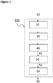
- Figure 1 shows a first general block diagram of an example system 100 for calculating cardiovascular heartbeat information from an electronic audio signal 10.
- the system comprises a signal receiving module 20, an audio processing module 30, a denoising module 40, a signal transformation module 50, and a beat detection module 60.
- the electronic audio signal 10 comprises information representative of a subject's voice signal in the time-domain.
- the subject's voice signal comprises a vowel audio sound of a certain duration and a fundamental frequency ( F0 in Figure 4 ).
- the electronic audio signal 10 may comprise a vowel audio sound that the subject has to sustain for a certain period or a vowel sound that is extracted from the subject's speech (e.g. by recognizing a vowel sound that has a certain duration or by stitching a plurality of vowel sounds).
- the electronic audio signal 10 may comprise a vowel audio sound having a certain minimum duration such as to comprise a detectable fundamental frequency characteristic of that subject.
- the electronic audio signal 10 may be a real-time signal or may be a non-real-time recorded signal that can be also postprocessed with a latency or in non-real-time.
- the signal receiving module 20 is configured for receiving the electronic audio signal 10, e.g. from an audio sensor or transducer, such as for example a microphone.
- the signal receiving module 20 may comprise wired or wireless transmission/receiving means to receive such electronic audio signal.
- the signal receiving module 20 may comprise a storage or memory in which such electronic audio signal is temporarily or permanently stored.
- the signal receiving module 20 may just comprise means to read the electronic audio signal from a memory or storage unit.
- the electronic audio signal is an analogue or digital audio signal in the kHz range.
- the signal receiving module 20 may comprise analogue to digital conversion and audio signal conditioning means.
- the audio processing module 30 is configured for generating a power spectral profile of a section of the electronic audio signal 10 and detecting the fundamental frequency (F0 in Figure 4 ) of the generated power spectral profile.
- a small portion of the voice is extracted from the electronic audio signal 10, and from it a power spectral profile is computed (see Figure 4 ).
- from the power spectral profile, around the first peak detected is considered the fundamental frequency of the voice signal.
- the audio processing module 30 may be also configured for calculating or detecting subsequent harmonics of the fundamental frequency, located at around 2, 3, 4, ...N times the fundamental frequency.
- the denoising module 40 is configured for filtering the received audio signal within a band around at least the detected fundamental frequency and thereby generating a denoised audio signal 45.
- the denoising unit performs a bandpass filtering of the electronic audio signal 10 around the fundamental frequency F0 to reduce the sources of noise and avoid aliasing.
- the bandpass filtering can be done up to about +/- 10Hz around the fundamental frequency.
- the denoising module may be further configured for filtering the received electronic audio signal 10 also within bands around one or more harmonics or multiples of the detected fundamental frequency (2F0,3F0, ...NF0 in Figure 4 ) and for generating one or more denoised audio signals.
- the bandpass filtering can be also done up to about +/- 10Hz around the harmonics.
- the denoising module 40 may generate a first denoised audio signal for the fundamental frequency and a second denoised audio signal for one of the corresponding harmonics.
- the denoising module 40 may generate also denoised audio signals for each of the harmonics (e.g. bandpass filtering the electronic audio signal 10 around the harmonic NF0 ).
- the denoising module may generate one denoised audio signal by bandpass filtering of the electronic audio signal 10 around the fundamental frequency F0 and around one or more harmonics.
- the signal transformation module 50 is configured for generating a time-domain intermediate signal 55 that captures frequency, amplitude and/or phase of the generated denoised audio signal 45.
- the signal transformation module may be configured for calculating the Hilbert transform of the denoised audio signal, the complex autocorrelation with M samples delay, and the instantaneous frequency, thereby generating a time-domain intermediate signal capturing the frequency of the denoised audio signal.
- the signal transformation module may be configured for generating an in-phase and quadrature signal of the denoised audio signal, with a carrier having a frequency that is the fundamental frequency, and calculating the L2 norm of the in-phase and quadrature signals over time, thereby generating a time-domain intermediate signal capturing the amplitude of the denoised audio signal.
- the signal transformation module may be configured for generating an in-phase and quadrature signal of the denoised audio signal, with a carrier having a frequency that is the fundamental frequency; and calculating the phase of the in-phase and quadrature signals, thereby generating a time-domain intermediate signal capturing the phase of the denoised audio signal.
- the signal transformation module is configured for combining calculated results from each of the denoised audio signals.
- the beat detection module 60 is configured for detecting and calculating heartbeat information 65 within a human cardiac band in the intermediate signal 55.
- said human cardiac band is around 40 to 200 bpm or 0.5Hz to 5.5Hz.
- the beat detection module is configured to detect heartbeat information within a human cardiac band in the intermediate signal, on the time-domain, the frequency domain and/or using wavelets techniques.
- said heartbeat information 65 comprises average heart rate, heartbeats and/or instantaneous heart rate.
- the beat detection module may be configured for performing a bandpass filtering of the intermediate signal around a human cardiac band.
- Figure 2A shows a block diagram of a first example signal transformation module 50 configured for generating a time-domain intermediate signal 55f that captures the frequency of the generated denoised audio signal 45.
- the signal transformation module is configured for calculating the Hilbert transform of the received denoised audio signal, calculating the complex autocorrelation of the Hilbert transform with M samples delay C M (t) , calculating the instantaneous frequency and low pass filtering the instantaneous frequency signal to avoid aliasing.
- the signal transformation module 50 may further be configured for down sampling the instantaneous frequency signal, which may be advantageous for real-time operation processing.
- the down-sampling is done to a human cardiac-like sampling frequency, e.g. 256 Hz.
- Figure 2B shows a block diagram of a second example signal transformation module 50 configured for generating a time-domain intermediate signal 55a that captures the amplitude of the generated denoised audio signal 45.
- the signal transformation module is configured for generating an in-phase I(t) and quadrature Q(t) signal of the denoised audio signal, with a carrier having a frequency that is the fundamental frequency and calculating the L2 norm of the in-phase and quadrature signals.
- the signal transformation module is configured for: generating a sine wave having the fundamental frequency, and multiplying the denoised audio signal by said sine wave, thereby generating the in-phase signal I(t); generating a cosine wave having the fundamental frequency, and multiplying the denoised audio signal by said cosine wave, thereby generating the quadrature signal Q(t); and calculating the sample-by-sample square root of the sum of the squares of the in-phase and quadrature signals over time.
- the signal transformation module 50 may further be configured for low pass filtering and/or down sampling the in-phase I(t) and/or the quadrature signal Q(t), which may be advantageous for avoiding aliasing or for real-time operation processing.
- the down-sampling is done to a human cardiac-like sampling frequency, e.g. 256 Hz.
- Figure 2C shows a block diagram of a third example signal transformation module 50 configured for generating a time-domain intermediate signal 55p that captures the amplitude of the generated denoised audio signal 45.
- the signal transformation module is configured for generating an in-phase I(t) and quadrature Q(t) signal of the denoised audio signal, with a carrier having a frequency that is the fundamental frequency and calculating the phase of the in-phase and quadrature signals.
- the signal transformation module is configured for: generating a sine wave having the fundamental frequency, and multiplying the denoised audio signal by said sine wave, thereby generating the in-phase signal I(t); generating a cosine wave having the fundamental frequency, and multiplying the denoised audio signal by said cosine wave, thereby generating the quadrature signal Q(t); and calculating the arctangent of the in-phase signal divided by the quadrature signal.
- the signal transformation module may be configured for compensating the phase by 2 pi shifts in order to enforce signal continuity.
- the signal transformation module 50 may further be configured for low pass filtering and/or down sampling the in-phase I(t) and/or the quadrature signal Q(t), which may be advantageous for avoiding aliasing or for real-time operation processing.
- the down-sampling is done to a human cardiac-like sampling frequency, e.g. 256 Hz.
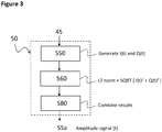
- Figure 3 shows a block diagram of a fourth example signal transformation module 50 configured for generating a time-domain intermediate signal 55a that captures the amplitude of a plurality of generated denoised audio signal 45.
- the signal transformation module is configured for: generating an in-phase I(t) and quadrature Q(t) signal for each of a plurality of denoised audio signals (e.g. one corresponding to the fundamental frequency and at least another one corresponding to one harmonic), with a carrier having a frequency that is the fundamental frequency; calculating the modulus of the in-phase and quadrature signals; and combining calculated amplitude results from each of the denoised audio signals.
- a plurality of denoised audio signals e.g. one corresponding to the fundamental frequency and at least another one corresponding to one harmonic
- the signal transformation module is configured for: generating an in-phase I(t) and quadrature Q(t) signal for each of a plurality of denoised audio signals (e.g. one corresponding to the fundamental frequency and at least another one corresponding to one harmonic), with a carrier having a frequency that is the fundamental frequency; combining generated in-phase I(t) and quadrature Q(t) signal values for each of the denoised audio signals; and calculating the modulus of the combined in-phase and quadrature signals.
- a plurality of denoised audio signals e.g. one corresponding to the fundamental frequency and at least another one corresponding to one harmonic
- Figure 3 only shows an example for a signal transformation module 50 configured for generating a time-domain intermediate signal 55a that captures the amplitude of a plurality of generated denoised audio signals 45, similar combinations can be done for a signal transformation module 50 configured for generating a time-domain intermediate signal 55p that captures the phase of a plurality of generated denoised audio signals 45.
- the signal transformation module is configured for: combining the received denoised audio signals; calculating the Hilbert transform of the combined audio signals; calculating the complex autocorrelation with M samples delay C M (t); calculating the instantaneous frequency, and low pass filtering the instantaneous frequency signal.
- the signal transformation module is configured for: calculating the Hilbert transform of each of the received denoised audio signals; calculating the complex autocorrelation with M samples delay C M (t) of each of the received denoised audio signals; calculating the instantaneous frequency for each of the C M (t); combining the instantaneous frequencies and low pass filtering the instantaneous frequency signal.
- Figure 4 illustrates a graph of an example electronic audio signal 10 in frequency domain, comprising a vowel audio sound having a fundamental frequency F0, and a plurality of harmonics 2F0, 3F0, 4F0, ...NF0.
- Further example demodulation signals generated by the signal transformation module 50 are also shown together with the synthetically generated cosine signal with frequencies F0 and a plurality of harmonics 2F0, 3F0, 4F0 used in the demodulation process.
- the frequency content of the input signal at the DC level is low to non-existing, whereas the demodulated signal levels in the DC area reflects the contents of the bands around the harmonics in the input signal. Such bandwidth contains the cardiac information to be decoded.
- Figure 5 illustrates a graph, in time-domain (left) and frequency domain (right), of an example intermediate signal 55p with phase information, generated by the signal transformation module 50.
- the intermediate signal 55p is compared with a reference cardiac pulse signal pz from a piezo-based sensor in the thumb measuring volumetric displacement.
- the time-domain graph (left) shows how the pulsatility of the signal 55p is similar to that of the reference cardiac pulse piezo signal pz.
- the frequency domain signal (right) reflects that the fundamental frequency of both the signals 55p (highest frequency peak) and reference pz (first peak) are in the exact same frequency location.
- FIG. 6 shows a second general block diagram of an example system 100 for calculating cardiovascular heartbeat information from an electronic audio signal 10, further comprising a heart rate information module 70.
- the heart rate information module is configured to receive heartbeat information 65 from the beat detection module 60 and calculate beat-to-beat information 75 such as beat-to-beat time delay, HRV and/or heart rate.
- the signal transformation beat detection module 60 and/or the heart rate information module 70 may provide information based on any of the time-domain intermediate signals 55 generated by the signal transformation module 50.
- the signal transformation beat detection module 60 and/or the heart rate information module 70 may provide multiple information based on a plurality of time-domain intermediate signals 55f, 55a, 55p generated by the signal transformation module 50.
- the signal transformation beat detection module 60 and/or the heart rate information module 70 may provide information based on a weighted or quality-related values derived from a plurality of time-domain intermediate signals 55f, 55a, 55p.
- system 100 for calculating cardiovascular heartbeat information may be implemented according to hardware and/or software state of the art techniques, comprising for example a microprocessor, microcontroller or digital signal processor that can understand and execute software program instructions. Some programmable hardware logic, ASIC and/or memory means may be specifically designed also for executing the method or parts of it according to example embodiments of the invention.
- the system may be implemented in an electronic device.
- the electronic device may be a wearable or a tethered device.
- the system may work in real-time, almost real-time (with a latency) or in post-processing.
- Figure 7 shows an example flow diagram 200 for calculating cardiovascular heartbeat information from an electronic audio signal 210.
- the method may be implemented in an electronic system or device, such as the ones described herein, or in a computer or processing unit.
- the electronic audio signal comprises information representative of a human voice signal in the time-domain, said human voice signal comprises a vowel audio sound of a certain duration and a fundamental frequency.
- the method comprises: 220, receiving the electronic audio signal; 230, generating a power spectral profile of a section of the electronic audio signal, and detecting the fundamental frequency of the generated power spectral profile; 240, filtering the received audio signal within a band around at least the detected fundamental frequency and thereby generating a denoised audio signal 245; 250, generating a time-domain intermediate signal 255 that captures frequency, amplitude and/or phase of the denoised audio signal; and 260, detecting and calculating heartbeat information 265 within a human cardiac band in the intermediate signal.
- said human cardiac band is around 40 to 200 bpm or 0.6Hz to 3.5Hz.
- the step 260 of detecting and calculating heartbeat information 265 within a human cardiac band in the intermediate signal can be performed, for example, on the time-domain, the frequency domain and/or using wavelets techniques.
- said heartbeat information 265 comprises average heart rate, heartbeats and/or instantaneous heart rate.
- the step 260 of detecting and calculating heartbeat information may comprise bandpass filtering of the intermediate signal 255 around a human cardiac band.
- Figure 8A shows a first example flow diagram for the step 250 of generating a time-domain intermediate signal 255f that captures frequency information.
- the method comprises: 2510, calculating a Hilbert transform of the denoised audio signal 245; 2520, calculating a complex autocorrelation with M samples delay of the Hilbert transform; and 2530, calculating the instantaneous frequency.
- Figure 8B shows a second example flow diagram for the step 250 of generating a time-domain intermediate signal 255a that captures amplitude information.
- the method comprises: 2550, generating an in-phase and a quadrature signal of the denoised audio signal 245, with a carrier having a frequency that is the fundamental frequency; and 2560, calculating the L2 norm of the in-phase and quadrature signals.
- Figure 8C shows a third example flow diagram for the step 250 of generating a time-domain intermediate signal 255p that captures phase information.
- the method comprises: 2550, generating an in-phase and a quadrature signal of the denoised audio signal, with a carrier having a frequency that is the fundamental frequency; and 2570, calculating the phase of the in-phase and quadrature signals.
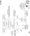
- Figure 9 shows a second example flow diagram 200' for calculating cardiovascular heartbeat information from an electronic audio signal 210.
- the electronic audio signal 210 may be generated by an audio acquisition module comprising a sensor (microphone), digitizer and signal conditioning of the audio signal. The output of the acquisition is a digital audio signal at a voice like sample rate (in the kHz range).
- the electronic audio signal 210 may be just stored on a memory or storage unit and read.
- the electronic audio signal 210 may be just received by wired or wireless transmission means.
- the method comprises extracting a power spectral profile of a small section of the electronic audio signal.
- a small portion of the voice is extracted and from it a power spectral profile is computed.
- the method comprises detecting the fundamental frequency of the voice signal from the power spectral profile.
- the first peak of the power spectral profile is the fundamental frequency.
- the subsequent harmonics should be at 2, 3, 4, etc times the fundamental frequency.
- the method comprises:
- Bandpass frequency, amplitude and phase signals the extracted frequency, amplitude and phase modulations in the voice are filtered in the bandwidth of interest of Cardiac systems. This is roughly in the bandwidth corresponding to heart rates between 40 and 200 beats per minute. It is key that the filtering delay of the pulse needs to be controlled and accounted for, as it needs to be compensated.
- the method further comprises: optionally, performing a bandpass of the frequency, amplitude and phase signals: the extracted frequency, amplitude and phase modulations in the voice are filtered in the bandwidth of interest of Cardiac systems. This is roughly in the bandwidth corresponding to heart rates between 40 and 200 beats per minute.
- bandpass filtering the filtering delay of the pulse needs to be controlled and accounted for, as it needs to be compensated. This delay may also be accounted for by design or compensated during a configuration phase.
- the method further comprises: extracting frequency, amplitude and phase relevant points from the signal related to heart beat information. This may be done in the time domain, frequency domain or using wavelets.
- a time fiducial points are extracted from the amplitude and phase, which is characteristic of every beat in the signal. Such fiducial point can be based on peak detection in the signal or its derivatives, zero crossings or other time domain fiducial points. It should be characteristic for each of the beats.
- the method further comprises calculating heartbeat information, e.g. calculating beat to beat time delay.
- heartbeat information e.g. calculating beat to beat time delay.
- the timing of point N is subtracted from the time in point N+1 to obtain the beat to beat time period.
- the method may further comprise calculating heart rate, e.g. the inverse is computed resulting in the heart rate.
- three different heart rate signals may be obtained: heart rate extracted from the voice frequency signal over time; heart rate extracted from the voice amplitude signal over time; heart rate extracted from the voice phase signal over time.
- Figure 10 shows a third example flow diagram 200" for calculating cardiovascular heartbeat information from an electronic audio signal 210.
- the denoised audio signal can be also processed at once (not per harmonic as in Figure 9 ).
- the step of filtering the received audio signal within a band around at least the detected fundamental frequency and thereby generating a denoised audio signal 245 comprises performing multiple band pass filters preserving the bandwidth around all the selected N harmonics (e.g. typically +/- 10Hz around each of the harmonics). This may be a composite filtering resulting from linearly combining filters for all the harmonics.
Landscapes
- Health & Medical Sciences (AREA)
- Life Sciences & Earth Sciences (AREA)
- Engineering & Computer Science (AREA)
- Physics & Mathematics (AREA)
- General Health & Medical Sciences (AREA)
- Public Health (AREA)
- Surgery (AREA)
- Biomedical Technology (AREA)
- Veterinary Medicine (AREA)
- Animal Behavior & Ethology (AREA)
- Molecular Biology (AREA)
- Medical Informatics (AREA)
- Cardiology (AREA)
- Heart & Thoracic Surgery (AREA)
- Signal Processing (AREA)
- Biophysics (AREA)
- Pathology (AREA)
- Physiology (AREA)
- Acoustics & Sound (AREA)
- Artificial Intelligence (AREA)
- Computer Vision & Pattern Recognition (AREA)
- Psychiatry (AREA)
- Computational Linguistics (AREA)
- Multimedia (AREA)
- Epidemiology (AREA)
- Audiology, Speech & Language Pathology (AREA)
- Human Computer Interaction (AREA)
- Nuclear Medicine, Radiotherapy & Molecular Imaging (AREA)
- Radiology & Medical Imaging (AREA)
- Measuring Pulse, Heart Rate, Blood Pressure Or Blood Flow (AREA)
Abstract
Description
- The present description relates generally to electronic systems for calculating cardiovascular heartbeat information and more specifically to an electronic system for calculating cardiovascular heartbeat information from an electronic audio signal input.
- There is an increasing need for providing cardiovascular heartbeat and heartrate information from human subjects. Some techniques advantageously provide such information using non-contact sensing techniques. An example method is shown in " Heart Rate Extraction from Vowel Speech Signals", by A. Mesleh et al, Journal of Computer Science and Technology 27(6): 1243-1251, Nov. 2012. Another known technique is described in " Automatic Recognition of Physiological Parameters in the Human Voice: Heart Rate and Skin Conductance", by B. Schuller et al, Proceedings of IEEE International Conference on Acoustics Speech and Signal Processing, pp. 7219-7223, 2013.
- There is a motivation to improve current state of the art electronic systems and methods for non-contact extraction of heart rate information from electronic human voice audio signals.
- A new and improved system and method for calculating cardiovascular heartbeat information is proposed herein, which allows to calculate a subject's cardiovascular heartbeat information from an electronic audio signal recorded from said subject. According to an example embodiment, the electronic system is advantageously able to calculate said subject's cardiovascular heartbeat information from an electronic audio signal using calculations in the time-domain. According to an example embodiment, the electronic system advantageously provides cardiovascular heartbeat information in a beat by beat basis, thereby being able to provide heart rate (HR), heart rate variability (HRV) and other beat-by-beat metric information. According to an example embodiment, the electronic system advantageously keeps the phase information of the signal and can identify when a specific heartbeat happens, in a time that can be related to absolute time. According to an example embodiment, the electronic system can advantageously process the audio signal and provide heartbeat information in real-time, while the subject is generating the audio signal. According to an example embodiment, the electronic system advantageously provides for a synchronous demodulation of the audio signal based on the fundamental frequency of a vowel audio sound. According to an example embodiment, the system can automatically adapt to different subjects' voices, thus avoiding the need for training configuration phases.
- According to an example embodiment, there is provided an electronic system for calculating cardiovascular heartbeat information from an electronic audio signal, wherein the electronic audio signal comprises information representative of a human voice signal in the time-domain, said human voice signal comprising a vowel audio sound of a certain duration and a fundamental frequency; and wherein the electronic system comprises: a signal receiving module configured for receiving the electronic audio signal; an audio processing module configured for generating a power spectral profile of a section of the electronic audio signal, and for detecting the fundamental frequency in the generated power spectral profile; a denoising module configured for filtering the received audio signal within a band around at least the detected fundamental frequency and thereby generating a denoised audio signal; a signal transformation module configured for generating a time-domain intermediate signal that captures frequency, amplitude and/or phase of the denoised audio signal; and a beat detection module configured for detecting and calculating heartbeat information within a human cardiac band in the intermediate signal.
- According to an example embodiment, the signal transformation module is configured for receiving the denoised audio signal and calculating the Hilbert transform; the complex autocorrelation with M samples delay; and the instantaneous frequency, thereby generating a time-domain intermediate signal capturing the frequency of the denoised audio signal.
- According to an example embodiment, the signal transformation module is configured for generating an in-phase and quadrature signal of the denoised audio signal, with a carrier having a frequency that is the fundamental frequency; and calculating the L2 norm of the in-phase and quadrature signals, thereby generating a time-domain intermediate signal capturing the amplitude of the denoised audio signal.
- According to an example embodiment, the signal transformation module is configured for generating an in-phase and quadrature signal of the denoised audio signal, with a carrier having a frequency that is the fundamental frequency; and calculating the phase of the in-phase and quadrature signals, thereby generating a time-domain intermediate signal capturing the phase of the denoised audio signal.
- According to an example embodiment, the denoising module is further configured for filtering the received audio signal also within bands around one or more multiples of the detected fundamental frequency and for generating one or more denoised audio signals.
- According to an example embodiment, the denoising module is configured for generating a plurality of denoised audio signals and the signal transformation module is configured for combining calculation results from each of the denoised audio signals.
- According to an example embodiment, the system further comprises a heart rate information calculation module configured for calculating HR and/or HRV information based on said heartbeat information provided by the beat detection module.
- The invention also relates to an electronic device comprising the electronic system for calculating cardiovascular heartbeat information according to embodiments herein described.
- The invention also relates to a method for, in an electronic system or device, calculating cardiovascular heartbeat information from an electronic audio signal, wherein the electronic audio signal comprises information representative of a human voice signal in the time-domain, said human voice signal comprising a vowel audio sound of a certain duration and a fundamental frequency; and the method comprising: receiving the electronic audio signal; generating a power spectral profile of a section of the electronic audio signal, and detecting the fundamental frequency in the generated power spectral profile; filtering the received audio signal within a band around at least the detected fundamental frequency and thereby generating a denoised audio signal; generating a time-domain intermediate signal that captures frequency, amplitude and/or phase of the denoised audio signal; and detecting and calculating heartbeat information within a human cardiac band in the intermediate signal.
- According to an example embodiment, the step of generating a time-domain intermediate signal that captures frequency of the denoised audio signal, comprises: calculating a Hilbert transform; calculating a complex autocorrelation with M samples delay; and calculating the instantaneous frequency.
- According to an example embodiment, the step of generating a time-domain intermediate signal that captures amplitude of the denoised audio signal, comprises: generating an in-phase and a quadrature signal of the denoised audio signal, with a carrier having a frequency that is the fundamental frequency; and calculating the L2 norm of the in-phase and quadrature signals.
- According to an example embodiment, the step of generating a time-domain intermediate signal that captures phase of the denoised audio signal (545), comprises: generating an in-phase and a quadrature signal of the denoised audio signal, with a carrier having a frequency that is the fundamental frequency; and calculating the phase of the in-phase and quadrature signals.
- The invention also relates to a computer program product comprising computer program code means adapted for calculating cardiovascular heartbeat information according to the methods herein described when said program is run on a computer, and to a computer readable storage medium comprising such computer program.
- The above and other aspects of the system and method according to the present description will be shown and explained with reference to the non-restrictive example embodiments described hereinafter.
-
Figure 1 shows a first general block diagram of an example system for calculating cardiovascular heartbeat information. -
Figure 2A shows a block diagram of a first example signal transformation module. -
Figure 2B shows a block diagram of a second example signal transformation module. -
Figure 2C shows a block diagram of a third example signal transformation module. -
Figure 3 shows a block diagram of a fourth example signal transformation module. -
Figure 4 illustrates a graph of an example electronic audio signal comprising a vowel audio sound having a fundamental frequency, in relation to other signals generated by the electronic system based on that fundamental frequency. -
Figure 5 illustrates a graph of an example time-domain intermediate signal with phase information, generated by the signal transformation module, and the comparison of the intermediate signal and a primary cardiac pulse signal in the frequency domain, showing the same location of the first harmonic. -
Figure 6 shows a second general block diagram of an example system for calculating cardiovascular heartbeat information, further comprising a heart rate information calculation module providing HR and/or HRV information. -
Figure 7 shows an example flow diagram for calculating cardiovascular heartbeat information from an electronic audio signal. -
Figure 8A shows a first example flow diagram for generating a time-domain intermediate signal that captures frequency information. -
Figure 8B shows a second example flow diagram for generating a time-domain intermediate signal that captures amplitude information. -
Figure 8C shows a third example flow diagram for generating a time-domain intermediate signal that captures phase information. -
Figure 9 shows a second example flow diagram for calculating cardiovascular heartbeat information from an electronic audio signal. -
Figure 10 shows a third example flow diagram for calculating cardiovascular heartbeat information from an electronic audio signal. - In the following, in the description of example embodiments, various features may be grouped together in a single embodiment, figure, or description thereof for the purpose of streamlining the disclosure and aiding in the understanding of one or more of the various inventive aspects. This is however not to be interpreted as the invention requiring more features than the ones expressly recited in the main claim. Furthermore, combinations of features of different embodiments are meant to be within the scope of the invention, as would be clearly understood by those skilled in the art. Additionally, in other instances, well-known methods, structures and techniques have not been shown in detail in order not to obscure the conciseness of the description.
-
Figure 1 shows a first general block diagram of anexample system 100 for calculating cardiovascular heartbeat information from anelectronic audio signal 10. The system comprises asignal receiving module 20, anaudio processing module 30, adenoising module 40, asignal transformation module 50, and abeat detection module 60. - The
electronic audio signal 10 comprises information representative of a subject's voice signal in the time-domain. The subject's voice signal comprises a vowel audio sound of a certain duration and a fundamental frequency (F0 inFigure 4 ). In some embodiments, theelectronic audio signal 10 may comprise a vowel audio sound that the subject has to sustain for a certain period or a vowel sound that is extracted from the subject's speech (e.g. by recognizing a vowel sound that has a certain duration or by stitching a plurality of vowel sounds). According to example embodiments, theelectronic audio signal 10 may comprise a vowel audio sound having a certain minimum duration such as to comprise a detectable fundamental frequency characteristic of that subject. Theelectronic audio signal 10 may be a real-time signal or may be a non-real-time recorded signal that can be also postprocessed with a latency or in non-real-time. - The
signal receiving module 20 is configured for receiving theelectronic audio signal 10, e.g. from an audio sensor or transducer, such as for example a microphone. In some embodiments, thesignal receiving module 20 may comprise wired or wireless transmission/receiving means to receive such electronic audio signal. In some embodiments, thesignal receiving module 20 may comprise a storage or memory in which such electronic audio signal is temporarily or permanently stored. In some embodiments, thesignal receiving module 20 may just comprise means to read the electronic audio signal from a memory or storage unit. In embodiments, the electronic audio signal is an analogue or digital audio signal in the kHz range. In some embodiments, thesignal receiving module 20 may comprise analogue to digital conversion and audio signal conditioning means. - The
audio processing module 30 is configured for generating a power spectral profile of a section of theelectronic audio signal 10 and detecting the fundamental frequency (F0 inFigure 4 ) of the generated power spectral profile. According to an example embodiment, a small portion of the voice is extracted from theelectronic audio signal 10, and from it a power spectral profile is computed (seeFigure 4 ). According to example embodiments, from the power spectral profile, around the first peak detected is considered the fundamental frequency of the voice signal. According to example embodiments, theaudio processing module 30 may be also configured for calculating or detecting subsequent harmonics of the fundamental frequency, located at around 2, 3, 4, ...N times the fundamental frequency. - The
denoising module 40 is configured for filtering the received audio signal within a band around at least the detected fundamental frequency and thereby generating adenoised audio signal 45. According to example embodiments, the denoising unit performs a bandpass filtering of theelectronic audio signal 10 around the fundamental frequency F0 to reduce the sources of noise and avoid aliasing. According to example embodiments, the bandpass filtering can be done up to about +/- 10Hz around the fundamental frequency. According to example embodiments, the denoising module may be further configured for filtering the receivedelectronic audio signal 10 also within bands around one or more harmonics or multiples of the detected fundamental frequency (2F0,3F0, ...NF0 inFigure 4 ) and for generating one or more denoised audio signals. According to example embodiments, the bandpass filtering can be also done up to about +/- 10Hz around the harmonics. For example, according to example embodiments, thedenoising module 40 may generate a first denoised audio signal for the fundamental frequency and a second denoised audio signal for one of the corresponding harmonics. Thedenoising module 40 may generate also denoised audio signals for each of the harmonics (e.g. bandpass filtering theelectronic audio signal 10 around the harmonic NF0). According to example embodiments, the denoising module may generate one denoised audio signal by bandpass filtering of theelectronic audio signal 10 around the fundamental frequency F0 and around one or more harmonics. - The
signal transformation module 50 is configured for generating a time-domainintermediate signal 55 that captures frequency, amplitude and/or phase of the generateddenoised audio signal 45. According to example embodiments, the signal transformation module may be configured for calculating the Hilbert transform of the denoised audio signal, the complex autocorrelation with M samples delay, and the instantaneous frequency, thereby generating a time-domain intermediate signal capturing the frequency of the denoised audio signal. According to example embodiments, the signal transformation module may be configured for generating an in-phase and quadrature signal of the denoised audio signal, with a carrier having a frequency that is the fundamental frequency, and calculating the L2 norm of the in-phase and quadrature signals over time, thereby generating a time-domain intermediate signal capturing the amplitude of the denoised audio signal. According to example embodiments, the signal transformation module may be configured for generating an in-phase and quadrature signal of the denoised audio signal, with a carrier having a frequency that is the fundamental frequency; and calculating the phase of the in-phase and quadrature signals, thereby generating a time-domain intermediate signal capturing the phase of the denoised audio signal. According to example embodiments, when thedenoising module 40 is configured for generating a plurality of denoisedaudio signal 45 corresponding to the detected fundamental frequency and one or more harmonics, the signal transformation module is configured for combining calculated results from each of the denoised audio signals. - The
beat detection module 60 is configured for detecting and calculatingheartbeat information 65 within a human cardiac band in theintermediate signal 55. According to example embodiments, said human cardiac band is around 40 to 200 bpm or 0.5Hz to 5.5Hz. According to example embodiments, the beat detection module is configured to detect heartbeat information within a human cardiac band in the intermediate signal, on the time-domain, the frequency domain and/or using wavelets techniques. According to example embodiments, saidheartbeat information 65 comprises average heart rate, heartbeats and/or instantaneous heart rate. According to example embodiments, the beat detection module may be configured for performing a bandpass filtering of the intermediate signal around a human cardiac band. -
Figure 2A shows a block diagram of a first examplesignal transformation module 50 configured for generating a time-domainintermediate signal 55f that captures the frequency of the generateddenoised audio signal 45. According to example embodiments, the signal transformation module is configured for calculating the Hilbert transform of the received denoised audio signal, calculating the complex autocorrelation of the Hilbert transform with M samples delay CM(t), calculating the instantaneous frequency and low pass filtering the instantaneous frequency signal to avoid aliasing. According to example embodiments, thesignal transformation module 50 may further be configured for down sampling the instantaneous frequency signal, which may be advantageous for real-time operation processing. According to example embodiments, the down-sampling is done to a human cardiac-like sampling frequency, e.g. 256 Hz. -
Figure 2B shows a block diagram of a second examplesignal transformation module 50 configured for generating a time-domainintermediate signal 55a that captures the amplitude of the generateddenoised audio signal 45. According to example embodiments, the signal transformation module is configured for generating an in-phase I(t) and quadrature Q(t) signal of the denoised audio signal, with a carrier having a frequency that is the fundamental frequency and calculating the L2 norm of the in-phase and quadrature signals. According to example embodiments, the signal transformation module is configured for: generating a sine wave having the fundamental frequency, and multiplying the denoised audio signal by said sine wave, thereby generating the in-phase signal I(t); generating a cosine wave having the fundamental frequency, and multiplying the denoised audio signal by said cosine wave, thereby generating the quadrature signal Q(t); and calculating the sample-by-sample square root of the sum of the squares of the in-phase and quadrature signals over time. According to example embodiments, thesignal transformation module 50 may further be configured for low pass filtering and/or down sampling the in-phase I(t) and/or the quadrature signal Q(t), which may be advantageous for avoiding aliasing or for real-time operation processing. According to example embodiments, the down-sampling is done to a human cardiac-like sampling frequency, e.g. 256 Hz. -
Figure 2C shows a block diagram of a third examplesignal transformation module 50 configured for generating a time-domainintermediate signal 55p that captures the amplitude of the generateddenoised audio signal 45. According to example embodiments, the signal transformation module is configured for generating an in-phase I(t) and quadrature Q(t) signal of the denoised audio signal, with a carrier having a frequency that is the fundamental frequency and calculating the phase of the in-phase and quadrature signals. According to example embodiments, the signal transformation module is configured for: generating a sine wave having the fundamental frequency, and multiplying the denoised audio signal by said sine wave, thereby generating the in-phase signal I(t); generating a cosine wave having the fundamental frequency, and multiplying the denoised audio signal by said cosine wave, thereby generating the quadrature signal Q(t); and calculating the arctangent of the in-phase signal divided by the quadrature signal. According to example embodiments, the signal transformation module may be configured for compensating the phase by 2 pi shifts in order to enforce signal continuity. According to example embodiments, thesignal transformation module 50 may further be configured for low pass filtering and/or down sampling the in-phase I(t) and/or the quadrature signal Q(t), which may be advantageous for avoiding aliasing or for real-time operation processing. According to example embodiments, the down-sampling is done to a human cardiac-like sampling frequency, e.g. 256 Hz. -
Figure 3 shows a block diagram of a fourth examplesignal transformation module 50 configured for generating a time-domainintermediate signal 55a that captures the amplitude of a plurality of generateddenoised audio signal 45. According to example embodiments, the signal transformation module is configured for: generating an in-phase I(t) and quadrature Q(t) signal for each of a plurality of denoised audio signals (e.g. one corresponding to the fundamental frequency and at least another one corresponding to one harmonic), with a carrier having a frequency that is the fundamental frequency; calculating the modulus of the in-phase and quadrature signals; and combining calculated amplitude results from each of the denoised audio signals. According to example embodiments, the signal transformation module is configured for: generating an in-phase I(t) and quadrature Q(t) signal for each of a plurality of denoised audio signals (e.g. one corresponding to the fundamental frequency and at least another one corresponding to one harmonic), with a carrier having a frequency that is the fundamental frequency; combining generated in-phase I(t) and quadrature Q(t) signal values for each of the denoised audio signals; and calculating the modulus of the combined in-phase and quadrature signals. - Although
Figure 3 only shows an example for asignal transformation module 50 configured for generating a time-domainintermediate signal 55a that captures the amplitude of a plurality of generated denoised audio signals 45, similar combinations can be done for asignal transformation module 50 configured for generating a time-domainintermediate signal 55p that captures the phase of a plurality of generated denoised audio signals 45. According to example embodiments, the signal transformation module is configured for: combining the received denoised audio signals; calculating the Hilbert transform of the combined audio signals; calculating the complex autocorrelation with M samples delay CM(t); calculating the instantaneous frequency, and low pass filtering the instantaneous frequency signal. According to example embodiments, the signal transformation module is configured for: calculating the Hilbert transform of each of the received denoised audio signals; calculating the complex autocorrelation with M samples delay CM(t) of each of the received denoised audio signals; calculating the instantaneous frequency for each of the CM(t); combining the instantaneous frequencies and low pass filtering the instantaneous frequency signal. -
Figure 4 illustrates a graph of an exampleelectronic audio signal 10 in frequency domain, comprising a vowel audio sound having a fundamental frequency F0, and a plurality of harmonics 2F0, 3F0, 4F0, ...NF0. Further example demodulation signals generated by thesignal transformation module 50 are also shown together with the synthetically generated cosine signal with frequencies F0 and a plurality of harmonics 2F0, 3F0, 4F0 used in the demodulation process. It shall be noted that the frequency content of the input signal at the DC level is low to non-existing, whereas the demodulated signal levels in the DC area reflects the contents of the bands around the harmonics in the input signal. Such bandwidth contains the cardiac information to be decoded. -
Figure 5 illustrates a graph, in time-domain (left) and frequency domain (right), of an exampleintermediate signal 55p with phase information, generated by thesignal transformation module 50. Theintermediate signal 55p is compared with a reference cardiac pulse signal pz from a piezo-based sensor in the thumb measuring volumetric displacement. The time-domain graph (left) shows how the pulsatility of thesignal 55p is similar to that of the reference cardiac pulse piezo signal pz. The frequency domain signal (right) reflects that the fundamental frequency of both thesignals 55p (highest frequency peak) and reference pz (first peak) are in the exact same frequency location. -
Figure 6 shows a second general block diagram of anexample system 100 for calculating cardiovascular heartbeat information from anelectronic audio signal 10, further comprising a heartrate information module 70. The heart rate information module is configured to receiveheartbeat information 65 from thebeat detection module 60 and calculate beat-to-beat information 75 such as beat-to-beat time delay, HRV and/or heart rate. According to example embodiments, the signal transformation beatdetection module 60 and/or the heartrate information module 70 may provide information based on any of the time-domainintermediate signals 55 generated by thesignal transformation module 50. According to example embodiments, the signal transformation beatdetection module 60 and/or the heartrate information module 70 may provide multiple information based on a plurality of time-domainintermediate signals signal transformation module 50. According to example embodiments, the signal transformation beatdetection module 60 and/or the heartrate information module 70 may provide information based on a weighted or quality-related values derived from a plurality of time-domainintermediate signals - It shall be noted that the
system 100 for calculating cardiovascular heartbeat information according to embodiments of the invention may be implemented according to hardware and/or software state of the art techniques, comprising for example a microprocessor, microcontroller or digital signal processor that can understand and execute software program instructions. Some programmable hardware logic, ASIC and/or memory means may be specifically designed also for executing the method or parts of it according to example embodiments of the invention. The system may be implemented in an electronic device. The electronic device may be a wearable or a tethered device. The system may work in real-time, almost real-time (with a latency) or in post-processing. -
Figure 7 shows an example flow diagram 200 for calculating cardiovascular heartbeat information from anelectronic audio signal 210. The method may be implemented in an electronic system or device, such as the ones described herein, or in a computer or processing unit. The electronic audio signal comprises information representative of a human voice signal in the time-domain, said human voice signal comprises a vowel audio sound of a certain duration and a fundamental frequency. The method comprises: 220, receiving the electronic audio signal; 230, generating a power spectral profile of a section of the electronic audio signal, and detecting the fundamental frequency of the generated power spectral profile; 240, filtering the received audio signal within a band around at least the detected fundamental frequency and thereby generating adenoised audio signal 245; 250, generating a time-domainintermediate signal 255 that captures frequency, amplitude and/or phase of the denoised audio signal; and 260, detecting and calculatingheartbeat information 265 within a human cardiac band in the intermediate signal. - According to example embodiments, said human cardiac band is around 40 to 200 bpm or 0.6Hz to 3.5Hz. According to example embodiments, the
step 260 of detecting and calculatingheartbeat information 265 within a human cardiac band in the intermediate signal, can be performed, for example, on the time-domain, the frequency domain and/or using wavelets techniques. According to example embodiments, saidheartbeat information 265 comprises average heart rate, heartbeats and/or instantaneous heart rate. According to example embodiments, thestep 260 of detecting and calculating heartbeat information may comprise bandpass filtering of theintermediate signal 255 around a human cardiac band. -
Figure 8A shows a first example flow diagram for thestep 250 of generating a time-domainintermediate signal 255f that captures frequency information. The method comprises: 2510, calculating a Hilbert transform of thedenoised audio signal 245; 2520, calculating a complex autocorrelation with M samples delay of the Hilbert transform; and 2530, calculating the instantaneous frequency. -
Figure 8B shows a second example flow diagram for thestep 250 of generating a time-domainintermediate signal 255a that captures amplitude information. The method comprises: 2550, generating an in-phase and a quadrature signal of thedenoised audio signal 245, with a carrier having a frequency that is the fundamental frequency; and 2560, calculating the L2 norm of the in-phase and quadrature signals. -
Figure 8C shows a third example flow diagram for thestep 250 of generating a time-domainintermediate signal 255p that captures phase information. The method comprises: 2550, generating an in-phase and a quadrature signal of the denoised audio signal, with a carrier having a frequency that is the fundamental frequency; and 2570, calculating the phase of the in-phase and quadrature signals. -
Figure 9 shows a second example flow diagram 200' for calculating cardiovascular heartbeat information from anelectronic audio signal 210. According to an example embodiment, theelectronic audio signal 210 may be generated by an audio acquisition module comprising a sensor (microphone), digitizer and signal conditioning of the audio signal. The output of the acquisition is a digital audio signal at a voice like sample rate (in the kHz range). According to embodiments, theelectronic audio signal 210 may be just stored on a memory or storage unit and read. According to embodiments, theelectronic audio signal 210 may be just received by wired or wireless transmission means. According to an example embodiment, the method comprises extracting a power spectral profile of a small section of the electronic audio signal. According to embodiments, a small portion of the voice is extracted and from it a power spectral profile is computed. According to an example embodiment, the method comprises detecting the fundamental frequency of the voice signal from the power spectral profile. According to an embodiment, the first peak of the power spectral profile is the fundamental frequency. Based on the detection of the fundamental frequency the subsequent harmonics should be at 2, 3, 4, etc times the fundamental frequency. The method can be performed up to N harmonics. According to preferred embodiments, the method is performed for N=4, as higher number of harmonics do not provide substantially better results but represent a higher computation expense. According to an example embodiment, for each of the harmonics until N, the method comprises: - 1. Denoising the signal around the harmonic to reduce the sources of noise, e.g. typically +/- 10Hz around the Harmonic;
- 2a. Demodulating the signal following these steps
- Generating a Sine of the frequency of the Harmonic;
- Multiplying the filtered harmonic signal by the Sine, which results in the I(t) signal (In-phase);
- Optionally: low pass filtering the I(t) signal to avoid aliasing
- Optionally: down sampling the I(t) signal to a Cardiac-like (256Hz for instance) sampling frequency.
- Generating a Cosine of the frequency of the Harmonic;
- Multiplying the filtered harmonic signal by the Cosine, which results in the Q(t) signal (Quadrature);
- Optionally: Low pass filtering the Q(t) signal to avoid aliasing;
- Optionally: Down sampling the Q(t) signal to a Cardiac-like (256Hz for instance) sampling frequency.
- 2b. Performing complex autocorrelation, as alternative or in addition to demodulation method 2a, following these steps:
- Calculating the Hilbert transform of the signal;
- Calculating the complex autocorrelation with m samples delay: CM (t);
- Calculating the phase, φ(t), of the complex autocorrelation signal, i.e. the arctangent of the real divided by the complex part of CM(t);
- Calculating the instantaneous frequency from the phase by f = fs∗φ(t) / (2π m), where fs is sampling frequency;
- Low pass filtering the Cm(t) signal to avoid aliasing;
- Optionally: Down sampling the Cm(t) signal to a cardiac-like (256Hz for instance) sampling frequency.
- 3. Combining Harmonic results. The results from the harmonics need to be combined to generate a consolidated amplitude and phase signals. Two of the possible options for combination are the following:
- 3.1 Option 1: summing all the results: get the sum of I(t) for all harmonics, and same for Q(t). Then compute the frequency, amplitude and phase. Amplitude is the square root of the sum of the squares of I(t) and Q(t). Phase is the arctangent of I(t)/Q(t), which may be compensated by 2 pi shifts. Instantaneous frequency: calculate the phase, φ(t), of the complex autocorrelation signal, i.e. the arctangent of the real divided by the complex part of Cm(t). The instantaneous frequency is calculated from phase, φ(t) by finst = fs∗φ(t) / (2π m). fs is sampling frequency.
- 3.2 Option 2: Calculating all amplitude and phase and sum: for each of the harmonics compute an amplitude and phase, sum the results.
- Bandpass frequency, amplitude and phase signals: the extracted frequency, amplitude and phase modulations in the voice are filtered in the bandwidth of interest of Cardiac systems. This is roughly in the bandwidth corresponding to heart rates between 40 and 200 beats per minute. It is key that the filtering delay of the pulse needs to be controlled and accounted for, as it needs to be compensated.
- According to an example embodiment, the method further comprises: optionally, performing a bandpass of the frequency, amplitude and phase signals: the extracted frequency, amplitude and phase modulations in the voice are filtered in the bandwidth of interest of Cardiac systems. This is roughly in the bandwidth corresponding to heart rates between 40 and 200 beats per minute. When bandpass filtering is applied, the filtering delay of the pulse needs to be controlled and accounted for, as it needs to be compensated. This delay may also be accounted for by design or compensated during a configuration phase.
- According to an example embodiment, the method further comprises: extracting frequency, amplitude and phase relevant points from the signal related to heart beat information. This may be done in the time domain, frequency domain or using wavelets. According to an example embodiment, a time fiducial points are extracted from the amplitude and phase, which is characteristic of every beat in the signal. Such fiducial point can be based on peak detection in the signal or its derivatives, zero crossings or other time domain fiducial points. It should be characteristic for each of the beats.
- According to an example embodiment, the method further comprises calculating heartbeat information, e.g. calculating beat to beat time delay. According to an example embodiment, once the signal points are detected for all the beats, the timing of point N is subtracted from the time in point N+1 to obtain the beat to beat time period.
- According to an example embodiment, the method may further comprise calculating heart rate, e.g. the inverse is computed resulting in the heart rate. According to an example embodiment, three different heart rate signals may be obtained: heart rate extracted from the voice frequency signal over time; heart rate extracted from the voice amplitude signal over time; heart rate extracted from the voice phase signal over time.
-
Figure 10 shows a third example flow diagram 200" for calculating cardiovascular heartbeat information from anelectronic audio signal 210. According to an example embodiment, as an alternative to the block diagram per harmonic as shown inFigure 9 , the denoised audio signal can be also processed at once (not per harmonic as inFigure 9 ). According to an example embodiment, the step of filtering the received audio signal within a band around at least the detected fundamental frequency and thereby generating adenoised audio signal 245, comprises performing multiple band pass filters preserving the bandwidth around all the selected N harmonics (e.g. typically +/- 10Hz around each of the harmonics). This may be a composite filtering resulting from linearly combining filters for all the harmonics. According to an example embodiment, for the demodulation option, demodulating the signal by - Generating a signal including the sum of sines of the first N harmonics:

- Generating a signal including the sum of cosines of the first N harmonics:

- Multiplying the filtered audio by x(t) to get I(t)
- Multiplying the filtered audio by y(t) to get Q(t)
- According to an example embodiment, for the complex autocorrelation: performing the Hilbert transform of the filtered signal containing all harmonics (instead of doing it per harmonic). The other processing steps are equal as described above for
Figure 9 .
Claims (14)
- An electronic system (100) for calculating cardiovascular heartbeat information from an electronic audio signal (10), wherein the electronic audio signal comprises information representative of a human voice signal in the time-domain, said human voice signal comprising a vowel audio sound of a certain duration and a fundamental frequency (F0); and wherein the electronic system comprises:a signal receiving module (20) configured for receiving the electronic audio signal;an audio processing module (30) configured for generating a power spectral profile of a section of the electronic audio signal, and for detecting the fundamental frequency (F0) in the generated power spectral profile;a denoising module (40) configured for filtering the received audio signal within a band around at least the detected fundamental frequency (F0) and thereby generating a denoised audio signal (45);a signal transformation module (50) configured for generating a time-domain intermediate signal (55) that captures a frequency, an amplitude and/or a phase of the denoised audio signal (45); anda beat detection module (60) configured for detecting and calculating heartbeat information (65) within a human cardiac band in the intermediate signal (55).
- The system (100) according to claim 1, wherein the signal transformation module (50) is configured for receiving the denoised audio signal (45) and calculating a Hilbert transform (501); a complex autocorrelation with M samples delay (520); and an instantaneous frequency (530), thereby generating a time domain intermediate signal (55f) capturing the frequency of the denoised audio signal (45).
- The system (100) according to any preceding claim, wherein the signal transformation module (50) is configured for generating (550) an in-phase (I) and quadrature (Q) signal of the denoised audio signal, with a carrier having a frequency that is the fundamental frequency (F0); and calculating the L2 norm (560) of the in-phase and quadrature signals, thereby generating a time domain intermediate signal (55a) capturing the amplitude of the denoised audio signal (45).
- The system (100) according to any preceding claim, wherein the signal transformation module (50) is configured for generating (550) an in-phase (I) and quadrature (Q) signal of the denoised audio signal, with a carrier having a frequency that is the fundamental frequency (F0); and calculating the phase (570) of the in-phase and quadrature signals, thereby generating a time domain intermediate signal (55p) capturing the phase of the denoised audio signal (45).
- The system (100) according to any preceding claim, wherein the denoising module (40) is further configured for filtering the received audio signal also within bands around one or more multiples of the detected fundamental frequency (F0) and for generating one or more denoised audio signals (45).
- The system (100) according to claim 5, wherein the denoising module (40) is configured for generating a plurality of denoised audio signals (45) and the signal transformation module (50) is configured for combining calculation results (580) from each of the denoised audio signals (45).
- The system (100) according to any preceding claim, further comprising a heart rate information calculation module (70) configured for calculating HR and/or HRV information (75) based on said heartbeat information (65).
- An electronic device comprising the electronic system (100) for calculating cardiovascular heartbeat information according to any of the preceding claims.
- A method (200) for, in an electronic system or device, calculating cardiovascular heartbeat information from an electronic audio signal (210), wherein the electronic audio signal comprises information representative of a human voice signal in the time-domain, said human voice signal comprising a vowel audio sound of a certain duration and a fundamental frequency (F0); and the method comprising:receiving the electronic audio signal (220);generating (230) a power spectral profile of a section of the electronic audio signal, and detecting the fundamental frequency (F0) in the generated power spectral profile;filtering (240) the received audio signal within a band around at least the detected fundamental frequency (F0) and thereby generating a denoised audio signal (245);generating (250) a time-domain intermediate signal (255) that captures frequency, amplitude and/or phase of the denoised audio signal (245); anddetecting and calculating (260) heartbeat information (265) within a human cardiac band in the intermediate signal (255).
- The method according to claim 9, wherein the step of generating (250) a time-domain intermediate signal (255f) that captures the frequency of the denoised audio signal (245) comprises: calculating (2510) a Hilbert transform; calculating (2520) a complex autocorrelation with M samples delay; and calculating (2530) an instantaneous frequency.
- The method according to claims 9 or 10, wherein the step of generating (250) a time domain intermediate signal (255a) that captures the amplitude of the denoised audio signal (245), comprises: generating (2550) an in-phase (I) and quadrature (Q) signal of the denoised audio signal, with a carrier having a frequency that is the fundamental frequency (F0); and calculating (2560) the L2 norm of the in-phase and quadrature signals.
- The method according to any of claims 9 to 11, wherein the step of generating (250) a time-domain intermediate signal (255p) that captures the phase of the denoised audio signal (545), comprises: generating (2550) an in-phase (I) and quadrature (Q) signal of the denoised audio signal, with a carrier having a frequency that is the fundamental frequency (F0); and calculating (2570) the phase of the in-phase and quadrature signals.
- A computer program product comprising computer program code means adapted for calculating cardiovascular heartbeat information according to the method of any of claims 9 to 12 when said program is run on a computer.
- A computer readable storage medium comprising a computer program according to claim 13.
Applications Claiming Priority (1)
| Application Number | Priority Date | Filing Date | Title |
|---|---|---|---|
| EP19180559 | 2019-06-17 |
Publications (2)
| Publication Number | Publication Date |
|---|---|
| EP3754656A1 true EP3754656A1 (en) | 2020-12-23 |
| EP3754656B1 EP3754656B1 (en) | 2022-11-30 |
Family
ID=67211480
Family Applications (1)
| Application Number | Title | Priority Date | Filing Date |
|---|---|---|---|
| EP20180436.6A Active EP3754656B1 (en) | 2019-06-17 | 2020-06-17 | System and method for calculating cardiovascular heartbeat information from an electronic audio signal |
Country Status (2)
| Country | Link |
|---|---|
| US (1) | US11721358B2 (en) |
| EP (1) | EP3754656B1 (en) |
Families Citing this family (1)
| Publication number | Priority date | Publication date | Assignee | Title |
|---|---|---|---|---|
| CN116098589B (en) * | 2023-02-17 | 2025-05-02 | 无锡健芯半导体科技有限公司 | Bioelectric signal separation and noise reduction method, device and electronic device |
Citations (2)
| Publication number | Priority date | Publication date | Assignee | Title |
|---|---|---|---|---|
| US20180153427A1 (en) * | 2015-06-26 | 2018-06-07 | Resmed Limited | Diagnosis and monitoring of cardio-respiratory disorders |
| WO2018146690A1 (en) * | 2017-02-12 | 2018-08-16 | Cardiokol Ltd. | Verbal periodic screening for heart disease |
Family Cites Families (4)
| Publication number | Priority date | Publication date | Assignee | Title |
|---|---|---|---|---|
| WO2003081578A1 (en) * | 2002-03-21 | 2003-10-02 | U.S. Army Medical Research And Materiel Command | Methods and systems for detecting, measuring, and monitoring stress in speech |
| US8784311B2 (en) * | 2010-10-05 | 2014-07-22 | University Of Florida Research Foundation, Incorporated | Systems and methods of screening for medical states using speech and other vocal behaviors |
| ES2364401B2 (en) * | 2011-06-27 | 2011-12-23 | Universidad Politécnica de Madrid | METHOD AND SYSTEM FOR ESTIMATING PHYSIOLOGICAL PARAMETERS OF THE FONATION. |
| US10643639B2 (en) * | 2017-06-21 | 2020-05-05 | Ajit Arun Zadgaonkar | System and method for determining cardiac parameters and physiological conditions by analysing speech samples |
-
2020
- 2020-06-17 US US16/903,895 patent/US11721358B2/en active Active
- 2020-06-17 EP EP20180436.6A patent/EP3754656B1/en active Active
Patent Citations (2)
| Publication number | Priority date | Publication date | Assignee | Title |
|---|---|---|---|---|
| US20180153427A1 (en) * | 2015-06-26 | 2018-06-07 | Resmed Limited | Diagnosis and monitoring of cardio-respiratory disorders |
| WO2018146690A1 (en) * | 2017-02-12 | 2018-08-16 | Cardiokol Ltd. | Verbal periodic screening for heart disease |
Non-Patent Citations (5)
| Title |
|---|
| A. MESLEH ET AL.: "Heart Rate Extraction from Vowel Speech Signals", JOURNAL OF COMPUTER SCIENCE AND TECHNOLOGY, vol. 27, no. 6, November 2012 (2012-11-01), pages 1243 - 1251, XP035147779, DOI: 10.1007/s11390-012-1300-6 |
| A.K BARROS ET AL: "Heart instantaneous frequency (HIF): an alternative approach to extract heart rate variability", IEEE TRANSACTIONS ON BIOMEDICAL ENGINEERING, August 2001 (2001-08-01), New York, pages 850 - 855, XP055395199, Retrieved from the Internet <URL:http://ieeexplore.ieee.org/ielx5/10/20272/00936361.pdf?tp=&arnumber=936361&isnumber=20272> DOI: 10.1109/10.936361 * |
| ABDELWADOOD MESLEH ET AL: "Heart Rate Extraction from Vowel Speech Signals", JOURNAL OF COMPUTER SCIENCE AND TECHNOLOGY, KLUWER ACADEMIC PUBLISHERS, BO, vol. 27, no. 6, 15 November 2012 (2012-11-15), pages 1243 - 1251, XP035147779, ISSN: 1860-4749, DOI: 10.1007/S11390-012-1300-6 * |
| B. SCHULLER ET AL.: "Automatic Recognition of Physiological Parameters in the Human Voice: Heart Rate and Skin Conductance", PROCEEDINGS OF IEEE INTERNATIONAL CONFERENCE ON ACOUSTICS SPEECH AND SIGNAL PROCESSING, 2013, pages 7219 - 7223, XP032509252, DOI: 10.1109/ICASSP.2013.6639064 |
| KUMAR D ET AL: "Noise detection during heart sound recording using periodicity signatures;Noise detection during heart sound recording using periodicity signatures", PHYSIOLOGICAL MEASUREMENT, INSTITUTE OF PHYSICS PUBLISHING, BRISTOL, GB, vol. 32, no. 5, 8 April 2011 (2011-04-08), pages 599 - 618, XP020190419, ISSN: 0967-3334, DOI: 10.1088/0967-3334/32/5/008 * |
Also Published As
| Publication number | Publication date |
|---|---|
| US20200395040A1 (en) | 2020-12-17 |
| US11721358B2 (en) | 2023-08-08 |
| EP3754656B1 (en) | 2022-11-30 |
Similar Documents
| Publication | Publication Date | Title |
|---|---|---|
| US20150150515A1 (en) | Respiration rate extraction from cardiac signals | |
| JP2006526460A5 (en) | ||
| EP3678553B1 (en) | Diagnosis of pathologies using infrasonic signatures | |
| US20180228468A1 (en) | Diagnosis of pathologies using infrasonic signatures | |
| JP6304691B2 (en) | Heart sound noise removing apparatus, method and program thereof | |
| CN106510674A (en) | Method and device for removing interference of blood pressure signal and blood pressure detection system | |
| CN106073783A (en) | A kind of method extracting breathing rate from photoplethysmographic | |
| Kong et al. | Heart rate tracking using a wearable photoplethysmographic sensor during treadmill exercise | |
| JP2016182165A (en) | Biological signal processing device, biological signal processing program, computer readable recording medium recording biological signal processing program and biological signal processing method | |
| EP3754656B1 (en) | System and method for calculating cardiovascular heartbeat information from an electronic audio signal | |
| JP6467044B2 (en) | Shunt sound analysis device, shunt sound analysis method, computer program, and recording medium | |
| JPH11128185A (en) | Heart rate variability analysis method and apparatus | |
| Xie et al. | Heart rate estimation from ballistocardiography based on hilbert transform and phase vocoder | |
| US20260065924A1 (en) | Heart sound signal quality assessment method, electronic device and readable storage medium | |
| US11911136B2 (en) | System and method for calculating cardiac pulse transit or arrival time information | |
| Salman et al. | Automatic segmentation and detection of heart sound components S1, S2, S3 and S4 | |
| JP2002330935A (en) | Pulse fluctuation analysis device, pulse fluctuation analysis method, program, and recording medium | |
| WO2016165220A1 (en) | Traffic safety detection method and apparatus | |
| Varghees et al. | Two-channel heart sound segmentation framework using phonocardiogram and pulsatile signals | |
| HAMID | Systolic Phase Detection from Pulsed Doppler Ultrasound Signalusing EMD-DHT based Approach | |
| US20220323023A1 (en) | Method for determining respiratory rate | |
| CN109009059B (en) | Heart rate calculation method based on heart sounds | |
| Kumari et al. | R Peak Detection using empirical mode decomposition with Shannon energy envelope | |
| Mohanty et al. | R-peak detection using efficient technique for tachycardia detection | |
| Karlen et al. | Photoplethysmogram processing using an adaptive single frequency phase vocoder algorithm |
Legal Events
| Date | Code | Title | Description |
|---|---|---|---|
| PUAI | Public reference made under article 153(3) epc to a published international application that has entered the european phase |
Free format text: ORIGINAL CODE: 0009012 |
|
| STAA | Information on the status of an ep patent application or granted ep patent |
Free format text: STATUS: THE APPLICATION HAS BEEN PUBLISHED |
|
| AK | Designated contracting states |
Kind code of ref document: A1 Designated state(s): AL AT BE BG CH CY CZ DE DK EE ES FI FR GB GR HR HU IE IS IT LI LT LU LV MC MK MT NL NO PL PT RO RS SE SI SK SM TR |
|
| AX | Request for extension of the european patent |
Extension state: BA ME |
|
| STAA | Information on the status of an ep patent application or granted ep patent |
Free format text: STATUS: REQUEST FOR EXAMINATION WAS MADE |
|
| 17P | Request for examination filed |
Effective date: 20210622 |
|
| RBV | Designated contracting states (corrected) |
Designated state(s): AL AT BE BG CH CY CZ DE DK EE ES FI FR GB GR HR HU IE IS IT LI LT LU LV MC MK MT NL NO PL PT RO RS SE SI SK SM TR |
|
| GRAP | Despatch of communication of intention to grant a patent |
Free format text: ORIGINAL CODE: EPIDOSNIGR1 |
|
| STAA | Information on the status of an ep patent application or granted ep patent |
Free format text: STATUS: GRANT OF PATENT IS INTENDED |
|
| RIC1 | Information provided on ipc code assigned before grant |
Ipc: G10L 25/90 20130101ALN20220518BHEP Ipc: A61B 8/02 20060101ALI20220518BHEP Ipc: A61B 5/02 20060101ALI20220518BHEP Ipc: G10L 25/66 20130101AFI20220518BHEP |
|
| INTG | Intention to grant announced |
Effective date: 20220621 |
|
| RIN1 | Information on inventor provided before grant (corrected) |
Inventor name: MIHAJLOVIC, VOJKAN Inventor name: HERMELING, EVELIEN Inventor name: AGELL, CARLOS |
|
| GRAS | Grant fee paid |
Free format text: ORIGINAL CODE: EPIDOSNIGR3 |
|
| GRAA | (expected) grant |
Free format text: ORIGINAL CODE: 0009210 |
|
| STAA | Information on the status of an ep patent application or granted ep patent |
Free format text: STATUS: THE PATENT HAS BEEN GRANTED |
|
| AK | Designated contracting states |
Kind code of ref document: B1 Designated state(s): AL AT BE BG CH CY CZ DE DK EE ES FI FR GB GR HR HU IE IS IT LI LT LU LV MC MK MT NL NO PL PT RO RS SE SI SK SM TR |
|
| REG | Reference to a national code |
Ref country code: CH Ref legal event code: EP Ref country code: GB Ref legal event code: FG4D |
|
| REG | Reference to a national code |
Ref country code: AT Ref legal event code: REF Ref document number: 1535294 Country of ref document: AT Kind code of ref document: T Effective date: 20221215 Ref country code: DE Ref legal event code: R096 Ref document number: 602020006565 Country of ref document: DE |
|
| REG | Reference to a national code |
Ref country code: IE Ref legal event code: FG4D |
|
| REG | Reference to a national code |
Ref country code: LT Ref legal event code: MG9D |
|
| REG | Reference to a national code |
Ref country code: NL Ref legal event code: MP Effective date: 20221130 |
|
| PG25 | Lapsed in a contracting state [announced via postgrant information from national office to epo] |
Ref country code: SE Free format text: LAPSE BECAUSE OF FAILURE TO SUBMIT A TRANSLATION OF THE DESCRIPTION OR TO PAY THE FEE WITHIN THE PRESCRIBED TIME-LIMIT Effective date: 20221130 Ref country code: PT Free format text: LAPSE BECAUSE OF FAILURE TO SUBMIT A TRANSLATION OF THE DESCRIPTION OR TO PAY THE FEE WITHIN THE PRESCRIBED TIME-LIMIT Effective date: 20230331 Ref country code: NO Free format text: LAPSE BECAUSE OF FAILURE TO SUBMIT A TRANSLATION OF THE DESCRIPTION OR TO PAY THE FEE WITHIN THE PRESCRIBED TIME-LIMIT Effective date: 20230228 Ref country code: LT Free format text: LAPSE BECAUSE OF FAILURE TO SUBMIT A TRANSLATION OF THE DESCRIPTION OR TO PAY THE FEE WITHIN THE PRESCRIBED TIME-LIMIT Effective date: 20221130 Ref country code: FI Free format text: LAPSE BECAUSE OF FAILURE TO SUBMIT A TRANSLATION OF THE DESCRIPTION OR TO PAY THE FEE WITHIN THE PRESCRIBED TIME-LIMIT Effective date: 20221130 Ref country code: ES Free format text: LAPSE BECAUSE OF FAILURE TO SUBMIT A TRANSLATION OF THE DESCRIPTION OR TO PAY THE FEE WITHIN THE PRESCRIBED TIME-LIMIT Effective date: 20221130 |
|
| REG | Reference to a national code |
Ref country code: AT Ref legal event code: MK05 Ref document number: 1535294 Country of ref document: AT Kind code of ref document: T Effective date: 20221130 |
|
| PG25 | Lapsed in a contracting state [announced via postgrant information from national office to epo] |
Ref country code: RS Free format text: LAPSE BECAUSE OF FAILURE TO SUBMIT A TRANSLATION OF THE DESCRIPTION OR TO PAY THE FEE WITHIN THE PRESCRIBED TIME-LIMIT Effective date: 20221130 Ref country code: PL Free format text: LAPSE BECAUSE OF FAILURE TO SUBMIT A TRANSLATION OF THE DESCRIPTION OR TO PAY THE FEE WITHIN THE PRESCRIBED TIME-LIMIT Effective date: 20221130 Ref country code: LV Free format text: LAPSE BECAUSE OF FAILURE TO SUBMIT A TRANSLATION OF THE DESCRIPTION OR TO PAY THE FEE WITHIN THE PRESCRIBED TIME-LIMIT Effective date: 20221130 Ref country code: IS Free format text: LAPSE BECAUSE OF FAILURE TO SUBMIT A TRANSLATION OF THE DESCRIPTION OR TO PAY THE FEE WITHIN THE PRESCRIBED TIME-LIMIT Effective date: 20230330 Ref country code: HR Free format text: LAPSE BECAUSE OF FAILURE TO SUBMIT A TRANSLATION OF THE DESCRIPTION OR TO PAY THE FEE WITHIN THE PRESCRIBED TIME-LIMIT Effective date: 20221130 Ref country code: GR Free format text: LAPSE BECAUSE OF FAILURE TO SUBMIT A TRANSLATION OF THE DESCRIPTION OR TO PAY THE FEE WITHIN THE PRESCRIBED TIME-LIMIT Effective date: 20230301 |
|
| P01 | Opt-out of the competence of the unified patent court (upc) registered |
Effective date: 20230513 |
|
| PG25 | Lapsed in a contracting state [announced via postgrant information from national office to epo] |
Ref country code: NL Free format text: LAPSE BECAUSE OF FAILURE TO SUBMIT A TRANSLATION OF THE DESCRIPTION OR TO PAY THE FEE WITHIN THE PRESCRIBED TIME-LIMIT Effective date: 20221130 |
|
| PG25 | Lapsed in a contracting state [announced via postgrant information from national office to epo] |
Ref country code: SM Free format text: LAPSE BECAUSE OF FAILURE TO SUBMIT A TRANSLATION OF THE DESCRIPTION OR TO PAY THE FEE WITHIN THE PRESCRIBED TIME-LIMIT Effective date: 20221130 Ref country code: RO Free format text: LAPSE BECAUSE OF FAILURE TO SUBMIT A TRANSLATION OF THE DESCRIPTION OR TO PAY THE FEE WITHIN THE PRESCRIBED TIME-LIMIT Effective date: 20221130 Ref country code: EE Free format text: LAPSE BECAUSE OF FAILURE TO SUBMIT A TRANSLATION OF THE DESCRIPTION OR TO PAY THE FEE WITHIN THE PRESCRIBED TIME-LIMIT Effective date: 20221130 Ref country code: DK Free format text: LAPSE BECAUSE OF FAILURE TO SUBMIT A TRANSLATION OF THE DESCRIPTION OR TO PAY THE FEE WITHIN THE PRESCRIBED TIME-LIMIT Effective date: 20221130 Ref country code: CZ Free format text: LAPSE BECAUSE OF FAILURE TO SUBMIT A TRANSLATION OF THE DESCRIPTION OR TO PAY THE FEE WITHIN THE PRESCRIBED TIME-LIMIT Effective date: 20221130 Ref country code: AT Free format text: LAPSE BECAUSE OF FAILURE TO SUBMIT A TRANSLATION OF THE DESCRIPTION OR TO PAY THE FEE WITHIN THE PRESCRIBED TIME-LIMIT Effective date: 20221130 |
|
| PG25 | Lapsed in a contracting state [announced via postgrant information from national office to epo] |
Ref country code: SK Free format text: LAPSE BECAUSE OF FAILURE TO SUBMIT A TRANSLATION OF THE DESCRIPTION OR TO PAY THE FEE WITHIN THE PRESCRIBED TIME-LIMIT Effective date: 20221130 Ref country code: AL Free format text: LAPSE BECAUSE OF FAILURE TO SUBMIT A TRANSLATION OF THE DESCRIPTION OR TO PAY THE FEE WITHIN THE PRESCRIBED TIME-LIMIT Effective date: 20221130 |
|
| REG | Reference to a national code |
Ref country code: DE Ref legal event code: R097 Ref document number: 602020006565 Country of ref document: DE |
|
| PLBE | No opposition filed within time limit |
Free format text: ORIGINAL CODE: 0009261 |
|
| STAA | Information on the status of an ep patent application or granted ep patent |
Free format text: STATUS: NO OPPOSITION FILED WITHIN TIME LIMIT |
|
| 26N | No opposition filed |
Effective date: 20230831 |
|
| PG25 | Lapsed in a contracting state [announced via postgrant information from national office to epo] |
Ref country code: SI Free format text: LAPSE BECAUSE OF FAILURE TO SUBMIT A TRANSLATION OF THE DESCRIPTION OR TO PAY THE FEE WITHIN THE PRESCRIBED TIME-LIMIT Effective date: 20221130 |
|
| PG25 | Lapsed in a contracting state [announced via postgrant information from national office to epo] |
Ref country code: MC Free format text: LAPSE BECAUSE OF FAILURE TO SUBMIT A TRANSLATION OF THE DESCRIPTION OR TO PAY THE FEE WITHIN THE PRESCRIBED TIME-LIMIT Effective date: 20221130 |
|
| PG25 | Lapsed in a contracting state [announced via postgrant information from national office to epo] |
Ref country code: MC Free format text: LAPSE BECAUSE OF FAILURE TO SUBMIT A TRANSLATION OF THE DESCRIPTION OR TO PAY THE FEE WITHIN THE PRESCRIBED TIME-LIMIT Effective date: 20221130 |
|
| REG | Reference to a national code |
Ref country code: CH Ref legal event code: PL |
|
| REG | Reference to a national code |
Ref country code: BE Ref legal event code: MM Effective date: 20230630 |
|
| PG25 | Lapsed in a contracting state [announced via postgrant information from national office to epo] |
Ref country code: LU Free format text: LAPSE BECAUSE OF NON-PAYMENT OF DUE FEES Effective date: 20230617 |
|
| REG | Reference to a national code |
Ref country code: IE Ref legal event code: MM4A |
|
| PG25 | Lapsed in a contracting state [announced via postgrant information from national office to epo] |
Ref country code: LU Free format text: LAPSE BECAUSE OF NON-PAYMENT OF DUE FEES Effective date: 20230617 |
|
| PG25 | Lapsed in a contracting state [announced via postgrant information from national office to epo] |
Ref country code: IE Free format text: LAPSE BECAUSE OF NON-PAYMENT OF DUE FEES Effective date: 20230617 |
|
| PG25 | Lapsed in a contracting state [announced via postgrant information from national office to epo] |
Ref country code: IE Free format text: LAPSE BECAUSE OF NON-PAYMENT OF DUE FEES Effective date: 20230617 Ref country code: CH Free format text: LAPSE BECAUSE OF NON-PAYMENT OF DUE FEES Effective date: 20230630 |
|
| PG25 | Lapsed in a contracting state [announced via postgrant information from national office to epo] |
Ref country code: IT Free format text: LAPSE BECAUSE OF FAILURE TO SUBMIT A TRANSLATION OF THE DESCRIPTION OR TO PAY THE FEE WITHIN THE PRESCRIBED TIME-LIMIT Effective date: 20221130 Ref country code: BE Free format text: LAPSE BECAUSE OF NON-PAYMENT OF DUE FEES Effective date: 20230630 |
|
| PG25 | Lapsed in a contracting state [announced via postgrant information from national office to epo] |
Ref country code: BG Free format text: LAPSE BECAUSE OF FAILURE TO SUBMIT A TRANSLATION OF THE DESCRIPTION OR TO PAY THE FEE WITHIN THE PRESCRIBED TIME-LIMIT Effective date: 20221130 |
|
| PG25 | Lapsed in a contracting state [announced via postgrant information from national office to epo] |
Ref country code: BG Free format text: LAPSE BECAUSE OF FAILURE TO SUBMIT A TRANSLATION OF THE DESCRIPTION OR TO PAY THE FEE WITHIN THE PRESCRIBED TIME-LIMIT Effective date: 20221130 |
|
| GBPC | Gb: european patent ceased through non-payment of renewal fee |
Effective date: 20240617 |
|
| PG25 | Lapsed in a contracting state [announced via postgrant information from national office to epo] |
Ref country code: GB Free format text: LAPSE BECAUSE OF NON-PAYMENT OF DUE FEES Effective date: 20240617 |
|
| PGFP | Annual fee paid to national office [announced via postgrant information from national office to epo] |
Ref country code: DE Payment date: 20250520 Year of fee payment: 6 |
|
| PGFP | Annual fee paid to national office [announced via postgrant information from national office to epo] |
Ref country code: FR Payment date: 20250520 Year of fee payment: 6 |
|
| PG25 | Lapsed in a contracting state [announced via postgrant information from national office to epo] |
Ref country code: CY Free format text: LAPSE BECAUSE OF FAILURE TO SUBMIT A TRANSLATION OF THE DESCRIPTION OR TO PAY THE FEE WITHIN THE PRESCRIBED TIME-LIMIT; INVALID AB INITIO Effective date: 20200617 |
|
| PG25 | Lapsed in a contracting state [announced via postgrant information from national office to epo] |
Ref country code: HU Free format text: LAPSE BECAUSE OF FAILURE TO SUBMIT A TRANSLATION OF THE DESCRIPTION OR TO PAY THE FEE WITHIN THE PRESCRIBED TIME-LIMIT; INVALID AB INITIO Effective date: 20200617 |
|
| PG25 | Lapsed in a contracting state [announced via postgrant information from national office to epo] |
Ref country code: TR Free format text: LAPSE BECAUSE OF FAILURE TO SUBMIT A TRANSLATION OF THE DESCRIPTION OR TO PAY THE FEE WITHIN THE PRESCRIBED TIME-LIMIT Effective date: 20221130 |