EP3754647B1 - Instabilitätsminderung in einem system zur aktiven lärmreduzierung (anr) mit einem durchhörmodus - Google Patents
Instabilitätsminderung in einem system zur aktiven lärmreduzierung (anr) mit einem durchhörmodus Download PDFInfo
- Publication number
- EP3754647B1 EP3754647B1 EP20176467.7A EP20176467A EP3754647B1 EP 3754647 B1 EP3754647 B1 EP 3754647B1 EP 20176467 A EP20176467 A EP 20176467A EP 3754647 B1 EP3754647 B1 EP 3754647B1
- Authority
- EP
- European Patent Office
- Prior art keywords
- pass
- signal path
- anr
- signal
- variable gain
- Prior art date
- Legal status (The legal status is an assumption and is not a legal conclusion. Google has not performed a legal analysis and makes no representation as to the accuracy of the status listed.)
- Active
Links
Images


Classifications
-
- G—PHYSICS
- G10—MUSICAL INSTRUMENTS; ACOUSTICS
- G10K—SOUND-PRODUCING DEVICES; METHODS OR DEVICES FOR PROTECTING AGAINST, OR FOR DAMPING, NOISE OR OTHER ACOUSTIC WAVES IN GENERAL; ACOUSTICS NOT OTHERWISE PROVIDED FOR
- G10K11/00—Methods or devices for transmitting, conducting or directing sound in general; Methods or devices for protecting against, or for damping, noise or other acoustic waves in general
- G10K11/16—Methods or devices for protecting against, or for damping, noise or other acoustic waves in general
- G10K11/175—Methods or devices for protecting against, or for damping, noise or other acoustic waves in general using interference effects; Masking sound
- G10K11/178—Methods or devices for protecting against, or for damping, noise or other acoustic waves in general using interference effects; Masking sound by electro-acoustically regenerating the original acoustic waves in anti-phase
- G10K11/1781—Methods or devices for protecting against, or for damping, noise or other acoustic waves in general using interference effects; Masking sound by electro-acoustically regenerating the original acoustic waves in anti-phase characterised by the analysis of input or output signals, e.g. frequency range, modes, transfer functions
- G10K11/17821—Methods or devices for protecting against, or for damping, noise or other acoustic waves in general using interference effects; Masking sound by electro-acoustically regenerating the original acoustic waves in anti-phase characterised by the analysis of input or output signals, e.g. frequency range, modes, transfer functions characterised by the analysis of the input signals only
- G10K11/17827—Desired external signals, e.g. pass-through audio such as music or speech
-
- G—PHYSICS
- G10—MUSICAL INSTRUMENTS; ACOUSTICS
- G10K—SOUND-PRODUCING DEVICES; METHODS OR DEVICES FOR PROTECTING AGAINST, OR FOR DAMPING, NOISE OR OTHER ACOUSTIC WAVES IN GENERAL; ACOUSTICS NOT OTHERWISE PROVIDED FOR
- G10K11/00—Methods or devices for transmitting, conducting or directing sound in general; Methods or devices for protecting against, or for damping, noise or other acoustic waves in general
- G10K11/16—Methods or devices for protecting against, or for damping, noise or other acoustic waves in general
- G10K11/175—Methods or devices for protecting against, or for damping, noise or other acoustic waves in general using interference effects; Masking sound
- G10K11/178—Methods or devices for protecting against, or for damping, noise or other acoustic waves in general using interference effects; Masking sound by electro-acoustically regenerating the original acoustic waves in anti-phase
- G10K11/1781—Methods or devices for protecting against, or for damping, noise or other acoustic waves in general using interference effects; Masking sound by electro-acoustically regenerating the original acoustic waves in anti-phase characterised by the analysis of input or output signals, e.g. frequency range, modes, transfer functions
- G10K11/17821—Methods or devices for protecting against, or for damping, noise or other acoustic waves in general using interference effects; Masking sound by electro-acoustically regenerating the original acoustic waves in anti-phase characterised by the analysis of input or output signals, e.g. frequency range, modes, transfer functions characterised by the analysis of the input signals only
- G10K11/17823—Reference signals, e.g. ambient acoustic environment
-
- G—PHYSICS
- G10—MUSICAL INSTRUMENTS; ACOUSTICS
- G10K—SOUND-PRODUCING DEVICES; METHODS OR DEVICES FOR PROTECTING AGAINST, OR FOR DAMPING, NOISE OR OTHER ACOUSTIC WAVES IN GENERAL; ACOUSTICS NOT OTHERWISE PROVIDED FOR
- G10K11/00—Methods or devices for transmitting, conducting or directing sound in general; Methods or devices for protecting against, or for damping, noise or other acoustic waves in general
- G10K11/16—Methods or devices for protecting against, or for damping, noise or other acoustic waves in general
- G10K11/175—Methods or devices for protecting against, or for damping, noise or other acoustic waves in general using interference effects; Masking sound
- G10K11/178—Methods or devices for protecting against, or for damping, noise or other acoustic waves in general using interference effects; Masking sound by electro-acoustically regenerating the original acoustic waves in anti-phase
- G10K11/1783—Methods or devices for protecting against, or for damping, noise or other acoustic waves in general using interference effects; Masking sound by electro-acoustically regenerating the original acoustic waves in anti-phase handling or detecting of non-standard events or conditions, e.g. changing operating modes under specific operating conditions
- G10K11/17833—Methods or devices for protecting against, or for damping, noise or other acoustic waves in general using interference effects; Masking sound by electro-acoustically regenerating the original acoustic waves in anti-phase handling or detecting of non-standard events or conditions, e.g. changing operating modes under specific operating conditions by using a self-diagnostic function or a malfunction prevention function, e.g. detecting abnormal output levels
-
- G—PHYSICS
- G10—MUSICAL INSTRUMENTS; ACOUSTICS
- G10K—SOUND-PRODUCING DEVICES; METHODS OR DEVICES FOR PROTECTING AGAINST, OR FOR DAMPING, NOISE OR OTHER ACOUSTIC WAVES IN GENERAL; ACOUSTICS NOT OTHERWISE PROVIDED FOR
- G10K11/00—Methods or devices for transmitting, conducting or directing sound in general; Methods or devices for protecting against, or for damping, noise or other acoustic waves in general
- G10K11/16—Methods or devices for protecting against, or for damping, noise or other acoustic waves in general
- G10K11/175—Methods or devices for protecting against, or for damping, noise or other acoustic waves in general using interference effects; Masking sound
- G10K11/178—Methods or devices for protecting against, or for damping, noise or other acoustic waves in general using interference effects; Masking sound by electro-acoustically regenerating the original acoustic waves in anti-phase
- G10K11/1783—Methods or devices for protecting against, or for damping, noise or other acoustic waves in general using interference effects; Masking sound by electro-acoustically regenerating the original acoustic waves in anti-phase handling or detecting of non-standard events or conditions, e.g. changing operating modes under specific operating conditions
- G10K11/17837—Methods or devices for protecting against, or for damping, noise or other acoustic waves in general using interference effects; Masking sound by electro-acoustically regenerating the original acoustic waves in anti-phase handling or detecting of non-standard events or conditions, e.g. changing operating modes under specific operating conditions by retaining part of the ambient acoustic environment, e.g. speech or alarm signals that the user needs to hear
-
- G—PHYSICS
- G10—MUSICAL INSTRUMENTS; ACOUSTICS
- G10K—SOUND-PRODUCING DEVICES; METHODS OR DEVICES FOR PROTECTING AGAINST, OR FOR DAMPING, NOISE OR OTHER ACOUSTIC WAVES IN GENERAL; ACOUSTICS NOT OTHERWISE PROVIDED FOR
- G10K11/00—Methods or devices for transmitting, conducting or directing sound in general; Methods or devices for protecting against, or for damping, noise or other acoustic waves in general
- G10K11/16—Methods or devices for protecting against, or for damping, noise or other acoustic waves in general
- G10K11/175—Methods or devices for protecting against, or for damping, noise or other acoustic waves in general using interference effects; Masking sound
- G10K11/178—Methods or devices for protecting against, or for damping, noise or other acoustic waves in general using interference effects; Masking sound by electro-acoustically regenerating the original acoustic waves in anti-phase
- G10K11/1785—Methods, e.g. algorithms; Devices
- G10K11/17853—Methods, e.g. algorithms; Devices of the filter
-
- G—PHYSICS
- G10—MUSICAL INSTRUMENTS; ACOUSTICS
- G10K—SOUND-PRODUCING DEVICES; METHODS OR DEVICES FOR PROTECTING AGAINST, OR FOR DAMPING, NOISE OR OTHER ACOUSTIC WAVES IN GENERAL; ACOUSTICS NOT OTHERWISE PROVIDED FOR
- G10K11/00—Methods or devices for transmitting, conducting or directing sound in general; Methods or devices for protecting against, or for damping, noise or other acoustic waves in general
- G10K11/16—Methods or devices for protecting against, or for damping, noise or other acoustic waves in general
- G10K11/175—Methods or devices for protecting against, or for damping, noise or other acoustic waves in general using interference effects; Masking sound
- G10K11/178—Methods or devices for protecting against, or for damping, noise or other acoustic waves in general using interference effects; Masking sound by electro-acoustically regenerating the original acoustic waves in anti-phase
- G10K11/1787—General system configurations
- G10K11/17879—General system configurations using both a reference signal and an error signal
- G10K11/17881—General system configurations using both a reference signal and an error signal the reference signal being an acoustic signal, e.g. recorded with a microphone
-
- G—PHYSICS
- G10—MUSICAL INSTRUMENTS; ACOUSTICS
- G10K—SOUND-PRODUCING DEVICES; METHODS OR DEVICES FOR PROTECTING AGAINST, OR FOR DAMPING, NOISE OR OTHER ACOUSTIC WAVES IN GENERAL; ACOUSTICS NOT OTHERWISE PROVIDED FOR
- G10K11/00—Methods or devices for transmitting, conducting or directing sound in general; Methods or devices for protecting against, or for damping, noise or other acoustic waves in general
- G10K11/16—Methods or devices for protecting against, or for damping, noise or other acoustic waves in general
- G10K11/175—Methods or devices for protecting against, or for damping, noise or other acoustic waves in general using interference effects; Masking sound
- G10K11/178—Methods or devices for protecting against, or for damping, noise or other acoustic waves in general using interference effects; Masking sound by electro-acoustically regenerating the original acoustic waves in anti-phase
- G10K11/1787—General system configurations
- G10K11/17885—General system configurations additionally using a desired external signal, e.g. pass-through audio such as music or speech
-
- H—ELECTRICITY
- H04—ELECTRIC COMMUNICATION TECHNIQUE
- H04R—LOUDSPEAKERS, MICROPHONES, GRAMOPHONE PICK-UPS OR LIKE ACOUSTIC ELECTROMECHANICAL TRANSDUCERS; ELECTRIC HEARING AIDS; PUBLIC ADDRESS SYSTEMS
- H04R1/00—Details of transducers, loudspeakers or microphones
- H04R1/10—Earpieces; Attachments therefor ; Earphones; Monophonic headphones
- H04R1/1083—Reduction of ambient noise
-
- G—PHYSICS
- G10—MUSICAL INSTRUMENTS; ACOUSTICS
- G10K—SOUND-PRODUCING DEVICES; METHODS OR DEVICES FOR PROTECTING AGAINST, OR FOR DAMPING, NOISE OR OTHER ACOUSTIC WAVES IN GENERAL; ACOUSTICS NOT OTHERWISE PROVIDED FOR
- G10K11/00—Methods or devices for transmitting, conducting or directing sound in general; Methods or devices for protecting against, or for damping, noise or other acoustic waves in general
- G10K11/16—Methods or devices for protecting against, or for damping, noise or other acoustic waves in general
- G10K11/175—Methods or devices for protecting against, or for damping, noise or other acoustic waves in general using interference effects; Masking sound
-
- G—PHYSICS
- G10—MUSICAL INSTRUMENTS; ACOUSTICS
- G10K—SOUND-PRODUCING DEVICES; METHODS OR DEVICES FOR PROTECTING AGAINST, OR FOR DAMPING, NOISE OR OTHER ACOUSTIC WAVES IN GENERAL; ACOUSTICS NOT OTHERWISE PROVIDED FOR
- G10K2210/00—Details of active noise control [ANC] covered by G10K11/178 but not provided for in any of its subgroups
- G10K2210/10—Applications
- G10K2210/108—Communication systems, e.g. where useful sound is kept and noise is cancelled
- G10K2210/1081—Earphones, e.g. for telephones, ear protectors or headsets
-
- G—PHYSICS
- G10—MUSICAL INSTRUMENTS; ACOUSTICS
- G10K—SOUND-PRODUCING DEVICES; METHODS OR DEVICES FOR PROTECTING AGAINST, OR FOR DAMPING, NOISE OR OTHER ACOUSTIC WAVES IN GENERAL; ACOUSTICS NOT OTHERWISE PROVIDED FOR
- G10K2210/00—Details of active noise control [ANC] covered by G10K11/178 but not provided for in any of its subgroups
- G10K2210/30—Means
- G10K2210/301—Computational
- G10K2210/3028—Filtering, e.g. Kalman filters or special analogue or digital filters
-
- G—PHYSICS
- G10—MUSICAL INSTRUMENTS; ACOUSTICS
- G10K—SOUND-PRODUCING DEVICES; METHODS OR DEVICES FOR PROTECTING AGAINST, OR FOR DAMPING, NOISE OR OTHER ACOUSTIC WAVES IN GENERAL; ACOUSTICS NOT OTHERWISE PROVIDED FOR
- G10K2210/00—Details of active noise control [ANC] covered by G10K11/178 but not provided for in any of its subgroups
- G10K2210/30—Means
- G10K2210/301—Computational
- G10K2210/3056—Variable gain
-
- G—PHYSICS
- G10—MUSICAL INSTRUMENTS; ACOUSTICS
- G10K—SOUND-PRODUCING DEVICES; METHODS OR DEVICES FOR PROTECTING AGAINST, OR FOR DAMPING, NOISE OR OTHER ACOUSTIC WAVES IN GENERAL; ACOUSTICS NOT OTHERWISE PROVIDED FOR
- G10K2210/00—Details of active noise control [ANC] covered by G10K11/178 but not provided for in any of its subgroups
- G10K2210/50—Miscellaneous
- G10K2210/503—Diagnostics; Stability; Alarms; Failsafe
-
- H—ELECTRICITY
- H04—ELECTRIC COMMUNICATION TECHNIQUE
- H04R—LOUDSPEAKERS, MICROPHONES, GRAMOPHONE PICK-UPS OR LIKE ACOUSTIC ELECTROMECHANICAL TRANSDUCERS; ELECTRIC HEARING AIDS; PUBLIC ADDRESS SYSTEMS
- H04R1/00—Details of transducers, loudspeakers or microphones
- H04R1/10—Earpieces; Attachments therefor ; Earphones; Monophonic headphones
- H04R1/1041—Mechanical or electronic switches, or control elements
-
- H—ELECTRICITY
- H04—ELECTRIC COMMUNICATION TECHNIQUE
- H04R—LOUDSPEAKERS, MICROPHONES, GRAMOPHONE PICK-UPS OR LIKE ACOUSTIC ELECTROMECHANICAL TRANSDUCERS; ELECTRIC HEARING AIDS; PUBLIC ADDRESS SYSTEMS
- H04R2460/00—Details of hearing devices, i.e. of ear- or headphones covered by H04R1/10 or H04R5/033 but not provided for in any of their subgroups, or of hearing aids covered by H04R25/00 but not provided for in any of its subgroups
- H04R2460/01—Hearing devices using active noise cancellation
Definitions
- This disclosure generally relates to active noise reduction (ANR) devices having an operating mode in which external sounds from a user's environment are passed through, or reproduced, to the user.
- ANR active noise reduction
- Acoustic devices such as headphones can include active noise reduction (ANR) capabilities that block at least portions of ambient noise from reaching the ear of a user. Therefore, ANR devices create an acoustic isolation effect, which isolates the user, at least in part, from the environment.
- ANR devices have an operating mode referred to as aware mode, in which at least some ambient noise is deliberately passed through, or reproduced, to the user. In some cases, this operating mode may also be called “hear-through” mode, "talk-through” mode, or "pass-through” mode.
- US2013163775 A1 discloses that a gain of a signal representing sounds detected by a talk-through and/or feedforward ANR microphone of a talk-through function provided by a communications headset is reduced in response to a user of the communications headset speaking detected by a microphone.
- ANR Active Noise Reduction
- a pass-through signal flow path can be included to implement a feature that may be referred to as "aware mode.”
- this feature may also be called “hear-through” mode, "talk-through” mode, or "pass-through” mode.
- the ANR system is configured to detect external sounds that the user might want to hear and pass such sounds through to be heard by the user.
- Example ANR systems with aware mode are described in further detail below with reference to FIG. 1 .
- an ANR system with aware mode when deployed, for example, in noise canceling headphones, certain unstable conditions can cause the headphones to generate an acoustic artifact (e.g., a loud noise) that is uncomfortable for the user.
- Such unstable conditions can be caused by coupling between a driver and a feedforward microphone of the ANR system, for example, when adjusting the position of the headphones.
- the one or more actions taken can include adjusting the gain of the pass-through signal flow path using a variable gain amplifier, adjusting the coefficients for a filter disposed in the pass-through signal flow path, and disabling/enabling the pass-through signal flow path.
- the sensor-based approach described herein prevents unstable conditions before they occur and may provide additional improvements to the cost, weight, and assembly of ANR systems with aware mode.
- ANR Active Noise Reduction
- ANR headphones can provide potentially immersive listening experiences by reducing the effects of ambient noise and sounds.
- the term headphone includes various types of such personal acoustic devices such as in-ear, around-ear or over-the-ear headphones, earphones, earbuds, and hearing aids, as well as open-ear audio devices like audio eyeglasses, and shoulder or body-worn audio devices.
- ANR systems can also be used in automotive or other transportation systems (e.g., in cars, trucks, buses, aircrafts, boats or other vehicles) to cancel or attenuate unwanted noise produced by, for example, mechanical vibrations or engine harmonics.
- an ANR system can include an electroacoustic or electromechanical system that can be configured to cancel at least some of the unwanted noise (often referred to as "primary noise") based on the principle of superposition.
- the ANR system can identify an amplitude and phase of the primary noise and produce another signal (often referred to as an "anti-noise signal") of approximately equal amplitude and opposite phase.
- the anti-noise signal can then be combined with the primary noise such that both are substantially canceled at a desired location.
- the term substantially canceled, as used herein, may include reducing the "canceled" noise to a specified level or to within an acceptable tolerance, and does not require complete cancellation of all noise.
- ANR systems can be used in attenuating a wide range of noise signals, including, for example, broadband noise and/or low-frequency noise that may not be easily attenuated using passive noise control systems.
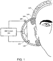
- FIG. 1 shows an example of an ANR system 100 deployed in a headphone 102.
- the headphone 102 includes an ear-cup 104 on each side, which fits on, around or over the ear of a user.
- the ear-cup 104 may include a layer 106 of soft material (e.g., soft foam) for a comfortable fit over the ear of the user.
- the ANR system 100 can include or otherwise be coupled with a feedforward sensor 108, a feedback sensor 110, and an acoustic transducer 112.
- the feedforward sensor 108 may be a microphone or another acoustic sensor and may be disposed on or near the outside of the ear-cup 104 to detect ambient noise.
- the feedback sensor 110 may be a microphone or another acoustic sensor and may be deployed proximate (e.g., within a few millimeters) to the user's ear canal and/or the transducer 112.
- the transducer 112 can be an acoustic transducer that radiates audio signals from an audio source device (not shown) that the headphone 102 is connected to and/or other signals from the ANR system 100.
- FIG. 1 illustrates an example where the ANR system is deployed in an around-ear headphone
- the ANR system could also be deployed in other form-factors, including in-ear headphones, on-ear headphones, or off-ear personal acoustic devices (e.g., devices that are designed to not contact a wearer's ears, but may be worn in the vicinity of the wearer's ears on the wearer's head or body).
- the ANR system 100 can be configured to process the signals detected by the feedforward sensor 108 and/or the feedback sensor 110 to produce an anti-noise signal that is provided to the transducer 112.
- the ANR system 100 can be of various types.
- the ANR system 100 is based on feedforward noise cancellation, in which the primary noise is sensed by the feedforward sensor 108 before the noise reaches a secondary source such as the transducer 112.
- the ANR system 100 can be based on feedback noise cancellation, where the ANR system 100 cancels the primary noise based on the residual noise detected by the feedback sensor 110 and without the benefit of the feedforward sensor 108.
- both feedforward and feedback noise cancellation are used.
- the ANR system 100 can be configured to control noise in various frequency bands. In some implementations, the ANR system 100 can be configured to control broadband noise such as white noise. In some implementations, the ANR system 100 can be configured to control narrow band noise such as harmonic noise from a vehicle engine.
- the ANR system 100 can include a configurable digital signal processor (DSP) and other circuitry for implementing various signal flow topologies and filter configurations. Examples of such DSPs are described in U.S. Patents 8,073,150 and 8,073,151 .
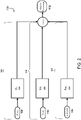
- the various signal flow topologies can be implemented in the ANR system 100 to enable functionalities such as audio equalization, feedback noise cancellation, and feedforward noise cancellation, among others.
- the signal flow topologies of the ANR system 100 can include a feedforward signal flow path 114 that drives the transducer 112 to generate an anti-noise signal (using, for example, a feedforward compensator 116) to reduce the effects of a noise signal picked up by the feedforward sensor 108.
- the signal flow topologies can include a feedback signal flow path 118 that drives the transducer 112 to generate an anti-noise signal (using, for example, a feedback compensator 120) to reduce the effects of a noise signal picked up by the feedback sensor 110.
- the signal flow topologies can also include an audio path 122 that includes circuitry (e.g., an equalizer 124) for processing input audio signals 126 such as music or communication signals, for playback over the transducer 112.
- the headphone 102 includes a feature that may be referred to as "aware mode.” In some cases, this feature may also be called “hear-through” mode, "talk-through” mode, or “pass-through” mode. In such a mode, the feedforward sensor 108 or other detection means can be used to detect external sounds that the user might want to hear, and the ANR system 100 can be configured to pass such sounds through to be reproduced by the transducer 112.
- the sensor used for the aware mode feature can be a sensor, such as a microphone, that is separate from the feedforward sensor 108.
- signals captured by multiple sensors can be used (e.g., using a beamforming process) to focus, for example, on the user's voice or another source of ambient sound.
- the headphone 102 can allow for multi-mode operations including a wideband aware mode in which the ANR functionality may be switched off or at least reduced, over at least a range of frequencies, to allow relatively wideband ambient sounds to reach the user.
- the ANR system 100 can also be used to shape a frequency response of the signals passing through the headphones.
- the feedforward compensator 116 and/or the feedback compensator 120 may be used to change an acoustic experience of having an earbud blocking the ear canal to one where ambient sounds (e.g., the user's own voice) sound more natural to the user.
- the ANR system 100 can allow a user to control the amount of ambient noise passed through the device while maintaining ANR functionalities, such as described in U.S. Patent No. 10,096,313 .
- the feedforward compensator 116 can include an ANR filter 302 and a pass-through filter 304 disposed in parallel, with the gain of the pass-through filter being adjustable by a factor C, as shown in FIG. 3 .
- the adjustable gain C may be implemented using a variable gain amplifier (VGA) 306 disposed in the pass-through signal flow path of the feedforward compensator 116.
- VGA variable gain amplifier
- the adjustable gain C may be implemented by selecting a set of coefficients for the pass-through filter 304. In some cases, the adjustable gain C may be implemented using a combination of adjustments to a variable gain amplifier 306 and the pass-through filter 304, each disposed in the pass-through signal flow path of the feedforward compensator 116.
- some conditions can lead to the onset of an unstable condition. For example, if the output of the transducer 112 gets fed back to the feedforward sensor 108, and the ANR system 100 passes the signal back to the transducer 112, a fast-deteriorating unstable condition could occur, resulting in an objectionable sound emanating from the transducer 112.
- This condition may be demonstrated, for example, by cupping a hand around a headphone to facilitate a feedback path between the transducer 112 and the feedback sensor 108.
- a feedback path may be established during use of the headphone, for example, if the user puts on a headgear (e.g., a head sock or winter hat) over the headphone 102.
- the unstable condition could occur due to changes in the transfer function of a secondary path (e.g., an acoustic path between the feedback sensor 110 and the transducer 112) of the ANR system 100. This can happen, for example, if the acoustic path between the transducer 112 and the feedback sensor 110 is changed in size or shape. This condition may be demonstrated, for example, by blocking the opening (e.g., using a finger or palm) through which sound emanates out of the headphone 102.
- a secondary path e.g., an acoustic path between the feedback sensor 110 and the transducer 112
- This condition may be demonstrated, for example, by blocking the opening (e.g., using a finger or palm) through which sound emanates out of the headphone 102.
- this condition may be referred to as a blocked-nozzle condition.
- This condition can result in practice, for example, during placement/removal of the headphone in the ear.
- This effect may be particularly observable in smaller headphones (e.g., in-ear earphones) or in-ear hearing aids, where the secondary path can change if the earphone or hearing-aid is moved while being worn. For example, moving an in-ear earphone or hearing aid can cause the volume of air in the corresponding secondary path to change, thereby causing the ANR system to be rendered unstable.
- pressure fluctuations in the ambient air can also cause the ANR system to go unstable.
- a vehicle e.g., a bus door
- an accompanying pressure change may cause an ANR system to become unstable.
- Another example of pressure fluctuations that can result in an unstable condition is a significant change in the ambient pressure of air relative to normal atmospheric pressures at sea level.
- Additional situations that may lead to an unstable condition in the ANR system can include deformation of the layer 106 of soft material of the headphone 102, temporarily adjusting the positioning of the headphone 102, or displacing the headphone 102, for example, by lying one's head down to fall asleep.
- ANR systems with aware mode are particularly prone to unstable conditions due to the relatively high levels of gain used to provide this feature, particularly for the feedforward signal flow path 114. If an unstable condition is not quickly detected and addressed, the unstable condition may cause the transducer 112 to produce acoustic artifacts (e.g., a loud audible noise, a squeal, a chirp, etc.), which may be uncomfortable for the wearer.
- acoustic artifacts e.g., a loud audible noise, a squeal, a chirp, etc.
- signal processing approaches can be used to detect and address existing instabilities in the ANR system 100. While such approaches can prevent the production of undesired acoustic artifacts in the presence of an instability, in some cases, they do not prevent the instability itself.
- Another approach to inhibiting the production of acoustic artifacts is to prevent unstable conditions from occurring at all.
- the technology described herein uses a sensor-based approach to detect the presence or absence of potential causes of unstable conditions and then takes one or more actions accordingly to prevent the occurrence of instabilities and acoustic artifacts in the ANR system.
- the one or more actions can include adjusting the gain of the pass-through signal flow path using a variable gain amplifier, adjusting the coefficients for a filter disposed in the pass-through signal flow path, and disabling/enabling the pass-through signal flow path.
- This sensor-based approach may provide the following benefits. First, rather than addressing existing instabilities, the technology described herein can prevent unstable conditions from occurring at all.
- the technology described herein may provide information about the cause of the unstable condition and allow the ANR system to learn to improve future performance. Furthermore, in some cases, the technology described herein may be less expensive, lighter, and less complex to implement than alternative approaches to preventing the production of acoustic artifacts.
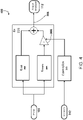
- FIG. 4 shows a block diagram of an ANR system 400 with sensor-based control of the gain for the pass-through signal flow path in accordance with technology described herein.
- the ANR system 400 includes an ANR filter 302 and a pass-through filter 304 disposed in parallel, with the gain of the pass-through filter being adjustable by a factor C.
- the outputs of the ANR filter 302 and the amplified pass-through filter 304 are summed to generate an output signal 308.
- the output signal 308 is used to drive an output transducer (e.g., output transducer 112) of the ANR system 400.
- the ANR system 304 further includes a controller 310, which modifies the adjustable gain C in response to receiving input from one or more sensors 312.
- the one or more sensors 312 provide information indicative of the existence (or absence) of a condition that is likely to cause instability in the pass-through signal path.
- the one or more sensors 312 may include an object sensor or proximity sensor that can detect an approaching hand, indicating that the ANR system 400 (e.g. a headphone) is about to be moved, which is likely to cause instability in the pass-through signal path.
- the one or more sensors 312 may detect that the ANR system 400 (e.g. a set of earbuds) is being removed from a user's ears, which may also be likely to cause instability in the pass-through signal flow path.
- the one or more sensors 312 may include capacitive proximity sensors, infrared (IR) sensors, light proximity sensors, etc. In some cases, the one or more sensors may also include the feedforward sensor 108 and/or a feedback sensor (e.g., feedback sensor 110). In some cases, the one or more sensors 312 may further include location sensors, accelerometers, date/time sensors, contact sensors etc.
- IR infrared
- the one or more sensors 312 may further include location sensors, accelerometers, date/time sensors, contact sensors etc.
- the controller 310 receives input signals captured from the one or more sensors 312 and determines whether or not the signals are indicative of the existence of a condition likely to cause instability in the pass-through signal flow path. In some cases, the controller may determine that a condition likely to cause instability exists if the one or more sensors 312 include a proximity sensor that detects that an object is less than a threshold distance from the one or more sensors 312, the feedforward sensor 108, a feedback sensor (e.g., feedback sensor 110), or the body of the ANR system 400 (e.g. headphone 102).
- the threshold distance may be a predetermined distance in the range of 0ft - 3ft (e.g., 1 inch, 2 inches, 3 inches, 6 inches, 1 foot, 2 feet, etc.). 1 foot corresponds to approximately 0,3048 meter. 1 inch corresponds to approximately 0,0254 meter.
- the controller 310 may determine that a condition likely to cause instability exists if the one or more sensors 312 include a proximity or contact sensor (e.g., a capacitive touch sensor) that detects that an object has made contact with a surface.
- a proximity or contact sensor e.g., a capacitive touch sensor
- one or more forms of artificial intelligence can be employed such that the controller 310 may learn to determine a condition's likelihood to cause instability in the ANR system 400 from training data, without being explicitly programmed for the task.
- machine learning may employ techniques such as regression to estimate the probability that the data collected by the one or more sensors 312 is indicative of the existence of a condition that will cause instability.
- one or more quantities may be defined to indicate the probability that instabilities will be present in the ANR system 400.
- a learning machine upon being trained, may be capable of outputting a numerical value that represents the probability of an instability occurring in the ANR system 400.
- one or more machine learning techniques may be employed.
- supervised learning techniques may be implemented in which training is based on a desired output (e.g., whether or not an instability occurred) that is known for an input (e.g., the data collected by the one or more sensors 312).
- Supervised learning can be considered an attempt to map inputs to outputs and then estimate outputs for previously unused inputs.
- Unsupervised learning techniques may also be used in which training is provided from known inputs but unknown outputs.
- Reinforcement learning techniques may also be employed in which the system can be considered as learning from consequences of actions taken (e.g., inputs values are known and feedback provides a performance measure).
- the implemented technique may employ two or more of these methodologies.
- the learning applied can be considered as not exactly supervised learning since the presence of instabilities in the ANR system 400 can be considered unknown prior to receiving feedback from a user.
- a reinforcement learning technique can be implemented.
- neural network techniques may be implemented using the information from the one or more sensors 312 (e.g., proximity data, audio data, etc.) to invoke training algorithms for automatically learning the likelihood that a condition exists that will cause an instability in the ANR system 400.
- Such neural networks typically employ a number of layers. Once the layers and number of units for each layer is defined, weights and thresholds of the neural network are typically set to minimize the prediction error through training of the network. Such techniques for minimizing error can be considered as fitting a model (represented by the network) to the training data.
- a function may be defined that quantifies error (e.g., a squared error function used in regression techniques).
- a neural network may be developed that is capable of estimating the likelihood that a condition will cause an instability in the ANR system 400.
- Other factors may also be accounted for during neutral network development. For example, a model may too closely attempt to fit data (e.g., fitting a curve to the extent that the modeling of an overall function is degraded). Such overfitting of a neural network may occur during the model training and one or more techniques may be implemented to reduce its effects.
- features may be used for training and using a machine learning system.
- Features may include, for example, data from the one or more sensors 312 including proximity data, audio data, date/time information, location data, etc.
- the features may be processed prior to being used for machine training (or for use by a pre-trained machine).
- a vector that represents a collection of sensor data may be normalized so that training data used can be considered as being placed on an equal basis.
- Such normalizing operations may take many forms. For example, an estimated value (e.g., average) and standard deviation (or variance) may be calculated for each feature. Once these quantities are calculated (e.g., the average and standard deviation), each feature is normalized using the data.
- the controller 310 may be used to determine the likelihood that a condition exists that will cause instabilities in the ANR system 400. Using any of the methods described above, if the controller 310 determines that a condition is likely to cause instability in the pass-through signal flow path, the controller 310 may reduce the variable gain C. By reducing the variable gain C, the controller 310 creates more headroom in the ANR system 400, which results in fewer opportunities for clipping, and provides more margin to prevent instabilities, for example, due to coupling between the feedforward sensors and the transducer.
- headroom refers to the difference between the signal-handling capabilities of an electrical component and the maximum level of the signal in the signal path, such as the feedforward signal path.
- reducing the variable gain C can be done by setting the variable gain C to zero, or a value substantially equal to zero, effectively shutting off any contribution from the pass-through signal flow path. This can be considered equivalent to "turning off" the aware mode.
- reducing the variable gain can be done by adjusting the gain of a variable gain amplifier (e.g., VGA 306).
- reducing the variable gain C can include selecting a set of coefficients for a filter disposed in the pass-through signal path, such as pass-through filter 304.
- the controller 310 may increase the variable gain C.
- Increasing the variable gain C can be achieved by setting the variable gain C to a value substantially different from zero (i.e., "turning on” aware mode), adjusting the gain of a VGA, and/or selecting a new set of coefficients for a filter disposed in the pass-through signal path, such as pass-through filter 304.
- the controller 310 may disable or enable the pass-through signal flow path.
- the controller 310 may disable and enable the pass-through signal flow path by controlling a switch (not shown).
- the switch may be disposed anywhere along the pass-through signal flow path (e.g., immediately before pass-through filter 304, immediately after pass-through filter 304, immediately after variable gain amplifier 306, etc.).
- the switch can be implemented as a hardware switch, as a software switch, or as a combination of both hardware and software components. When the pass-through signal flow path is disabled, this can be considered equivalent to "turning off" the aware mode. When the pass-through signal flow path is enabled, this can be considered equivalent to "turning on” the aware mode.
- the sensor-based approach disclosed herein may be combined with signal processing approaches (in which unstable conditions are mitigated upon occurrence) for detecting and addressing instabilities in the ANR system 400.
- a signal processing approach may be implemented to detect and address existing instabilities in the ANR system 400.
- the controller 310 can turn off aware mode by setting the adjustable gain C to zero.
- the data from the one or more sensors 312 can be recorded, and when the data from the one or more sensors 312 changes significantly (indicating a change in the condition that caused the instability), the sensor-based approach can then be used to enter aware mode once again (e.g., by increasing the adjustable gain C). Additional examples of signal-processing based approaches of instability mitigation can be found in US Applications 16/423,776 and 16/424,063 .
- a signal processing approach and a sensor-based approach can be implemented simultaneously.
- the sensor-based approach may act as a first defense to prevent the occurrence of any unstable conditions in the ANR system 400; however, in cases where the sensor-based approach does not succeed in detecting a condition likely to cause instability, a signal processing approach can then detect and address the existing instability, such that an acoustic artifact is never produced for the user.
- combining the disclosed sensor-based approach with signal processing approaches can enable active learning of the controller 310. Since signal processing approaches are able to detect existing instabilities, these approaches can provide automatic feedback to the controller 310 regarding the accuracy of its assessment about a condition's likelihood to cause instability in the ANR system 400. This can be used as additional and automatically generated training data for the machine learning techniques described above, enabling the ANR system 400 to continually learn and improve performance without requiring explicit feedback from the user.
- the arrangement of components along a feedforward path can include an analog microphone, an amplifier, an analog to digital converter (ADC), a feedforward compensator, in that order.
- ADC analog to digital converter
- This arrangement is similar to the arrangement of components depicted in FIG. 4 with the addition of an ADC between each feedforward microphone 108 and the feedforward compensator 116 (which, in this example, includes a variable gain amplifier (VGA)).
- VGA variable gain amplifier
- the arrangement of components along a feedforward path can include an analog microphone, an ADC, a VGA, and a feedforward compensator.
- FIG. 5 is a flowchart of an example process 500 for generating an output signal in an ANR system having a pass-through signal flow path with adjustable gain. At least a portion of the process 500 can be implemented using one or more processing devices such as DSPs described in U.S. Pat. Nos. 8,073,150 and 8,073,151 . Operations of the process 500 include receiving an input signal captured by one or more first sensors associated with an active noise reduction (ANR) device (502).
- the one or more first sensors include a feedforward sensor and/or a feedback sensor, such as the feedforward sensor 108 and the feedback sensor 112 described with reference to FIG.1 .
- the feedforward sensor is a feedforward microphone
- the feedback sensor is a feedback microphone.
- the ANR device can be an around-ear headphone such as the one described with reference to FIG. 1 .
- the ANR device can include, for example, in-ear headphones, on-ear headphones, open headphones, hearing aids, or other personal acoustic devices.
- the input signal captured by the one or more first sensors can be an audio signal representative of ambient noise associated with the ANR device.
- Operations of the process 500 further include processing the input signal using a first filter disposed in an ANR signal flow path to generate a first signal for an acoustic transducer of the ANR device (504).
- the first filter can be an ANR filter 302 such as the one described with reference to FIG. 3 and FIG. 4 .
- the first filter is disposed in a feedforward signal flow path of the ANR device, such as the feedforward signal flow path 114 described with reference to FIG. 2 .
- the acoustic transducer of the ANR device can be an acoustic speaker or other output transducer 112 such as the one described with reference to FIG. 4 .
- Operations of the process 500 further include processing the input signal in a pass-through signal flow path disposed in parallel with the ANR signal flow path to generate a second signal for the acoustic transducer, wherein the pass-through signal flow path is configured to allow at least a portion of the input signal to pass through to the acoustic transducer in accordance with a variable gain associated with the pass-through signal flow path (506).
- the pass-through signal flow path can be a signal flow path that includes a pass-through filter 304 such as the one described with reference to FIG. 3 and FIG. 4 .
- the pass-through signal flow path is disposed in parallel with the ANR signal flow path in a feedforward signal flow path of the ANR device, such as the feedforward signal flow path 114 described with reference to FIG. 2 .
- the variable gain associated with the pass-through signal flow path can be an adjustable gain such as the adjustable gain C described with reference to FIG. 3 and FIG. 4 .
- the portion of the input signal allowed to pass through to the acoustic transducer can correspond to a portion of ambient noise in the user's environment that the user may wish to hear, such as human voices, the sound of an approaching car, etc.
- Operations of the process 500 further include detecting using, one or more second sensors, an existence of a condition likely to cause instability in the pass-through signal flow path (508).
- the one or more second sensors can correspond to the one or more sensors 312 described with reference to FIG. 4 and can include capacity proximity sensors, infrared (IR) sensors, light proximity sensors, feedforward sensors (e.g. feedforward sensor 108), feedback sensors (e.g., feedback sensor 110), location sensors, accelerometers, date/time sensors, etc.
- detecting the condition likely to cause instability in the pass-through signal flow path can include detecting that an object is less than a threshold distance from the one or more second sensors (e.g. sensors 312) or the body of the ANR device.
- detecting the condition likely to cause instability in the pass-through signal flow path can include using one or more forms of artificial intelligence, such as machine learning to determine a condition's likelihood to cause instability in the ANR device from training data, without being explicitly programmed for the task.
- artificial intelligence such as machine learning
- Operations of the process 500 further include, responsive to detecting the existence of the condition likely to cause instability in the pass-through signal path, adjusting the variable gain associated with the pass-through signal path (510).
- adjusting the variable gain associated with the pass-through signal path can include reducing the variable gain.
- reducing the variable gain can include setting the variable gain to zero or a value substantially equal to zero; adjusting the gain of a variable gain amplifier (e.g., VGA 306); and/or selecting a set of coefficients for a filter disposed in the pass-through signal path, such as pass-through filter 304
- Operations of the process 500 further include generating a driver signal for the acoustic transducer using an output of the pass-through signal path, the output being based on the adjusted gain (512).
- the driver signal for the acoustic transducer can be the output signal 308 described with reference to FIG. 4 .
- the output of the pass-through signal path is used to generate the driver signal by summing the output with signals from other flow paths (e.g., an ANR signal flow path including ANR filter 302, a feedback signal flow path 118, an audio path 122, etc.).
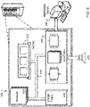
- FIG. 6 is block diagram of an example computer system 600 that can be used to perform operations described above.
- the system 600 includes a processor 610, a memory 620, a storage device 630, and an input/output device 640.
- Each of the components 610, 620, 630, and 640 can be interconnected, for example, using a system bus 650.
- the processor 610 is capable of processing instructions for execution within the system 600. In one implementation, the processor 610 is a single-threaded processor. In another implementation, the processor 610 is a multi-threaded processor.
- the processor 610 is capable of processing instructions stored in the memory 620 or on the storage device 630.
- the memory 620 stores information within the system 600.
- the memory 620 is a computer-readable medium.
- the memory 620 is a volatile memory unit.
- the memory 620 is a non-volatile memory unit.
- the storage device 630 is capable of providing mass storage for the system 600.
- the storage device 630 is a computer-readable medium.
- the storage device 630 can include, for example, a hard disk device, an optical disk device, a storage device that is shared over a network by multiple computing devices (e.g., a cloud storage device), or some other large capacity storage device.
- the input/output device 640 provides input/output operations for the system 600.
- the input/output device 640 can include one or more network interface devices, e.g., an Ethernet card, a serial communication device, e.g., and RS-232 port, and/or a wireless interface device, e.g., and 802.11 card.
- the input/output device can include driver devices configured to receive input data and send output data to other input/output devices, e.g., keyboard, printer and display devices 660, and acoustic transducers/speakers 670.
- Embodiments of the subject matter and the functional operations described in this specification can be implemented in digital electronic circuitry, in tangibly-embodied computer software or firmware, in computer hardware, including the structures disclosed in this specification and their structural equivalents, or in combinations of one or more of them.
- Embodiments of the subject matter described in this specification can be implemented as one or more computer programs, i.e., one or more modules of computer program instructions encoded on a tangible non transitory storage medium for execution by, or to control the operation of, data processing apparatus.
- the computer storage medium can be a machine-readable storage device, a machine-readable storage substrate, a random or serial access memory device, or a combination of one or more of them.
- the program instructions can be encoded on an artificially generated propagated signal, e.g., a machine-generated electrical, optical, or electromagnetic signal, which is generated to encode information for transmission to suitable receiver apparatus for execution by a data processing apparatus.
- data processing apparatus refers to data processing hardware and encompasses all kinds of apparatus, devices, and machines for processing data, including by way of example a programmable processor, a computer, or multiple processors or computers.
- the apparatus can also be, or further include, special purpose logic circuitry, e.g., an FPGA (field programmable gate array) or an ASIC (application specific integrated circuit).
- the apparatus can optionally include, in addition to hardware, code that creates an execution environment for computer programs, e.g., code that constitutes processor firmware, a protocol stack, a database management system, an operating system, or a combination of one or more of them.
- a computer program which may also be referred to or described as a program, software, a software application, an app, a module, a software module, a script, or code, can be written in any form of programming language, including compiled or interpreted languages, or declarative or procedural languages, and it can be deployed in any form, including as a stand-alone program or as a module, component, subroutine, or other unit suitable for use in a computing environment.
- a program may, but need not, correspond to a file in a file system.
- a program can be stored in a portion of a file that holds other programs or data, e.g., one or more scripts stored in a markup language document, in a single file dedicated to the program in question, or in multiple coordinated files, e.g., files that store one or more modules, sub programs, or portions of code.
- a computer program can be deployed to be executed on one computer or on multiple computers that are located at one site or distributed across multiple sites and interconnected by a data communication network.
- the processes and logic flows described in this specification can be performed by one or more programmable computers executing one or more computer programs to perform functions by operating on input data and generating output.
- the processes and logic flows can also be performed by special purpose logic circuitry, e.g., an FPGA or an ASIC, or by a combination of special purpose logic circuitry and one or more programmed computers.
- embodiments of the subject matter described in this specification can be implemented on a computer having a display device, e.g., a light emitting diode (LED) or liquid crystal display (LCD) monitor, for displaying information to the user and a keyboard and a pointing device, e.g., a mouse or a trackball, by which the user can provide input to the computer.
- a display device e.g., a light emitting diode (LED) or liquid crystal display (LCD) monitor
- a keyboard and a pointing device e.g., a mouse or a trackball
- Other kinds of devices can be used to provide for interaction with a user as well; for example, feedback provided to the user can be any form of sensory feedback, e.g., visual feedback, auditory feedback, or tactile feedback; and input from the user can be received in any form, including acoustic, speech, or tactile input.
- a computer can interact with a user by sending documents to and receiving documents from a device that is used by the user; for example, by sending web pages to a web browser on a user's device in response to requests received from the web browser.
- a computer can interact with a user by sending text messages or other forms of message to a personal device, e.g., a smartphone that is running a messaging application, and receiving responsive messages from the user in return.
- Embodiments of the subject matter described in this specification can be implemented in a computing system that includes a back end component, e.g., as a data server, or that includes a middleware component, e.g., an application server, or that includes a front end component, e.g., a client computer having a graphical user interface, a web browser, or an app through which a user can interact with an implementation of the subject matter described in this specification, or any combination of one or more such back end, middleware, or front end components.
- the components of the system can be interconnected by any form or medium of digital data communication, e.g., a communication network. Examples of communication networks include a local area network (LAN) and a wide area network (WAN), e.g., the Internet.
- LAN local area network
- WAN wide area network
- the computing system can include clients and servers.
- a client and server are generally remote from each other and typically interact through a communication network. The relationship of client and server arises by virtue of computer programs running on the respective computers and having a client-server relationship to each other.
- a server transmits data, e.g., an HTML page, to a user device, e.g., for purposes of displaying data to and receiving user input from a user interacting with the device, which acts as a client.
- Data generated at the user device e.g., a result of the user interaction, can be received at the server from the device.
Landscapes
- Physics & Mathematics (AREA)
- Engineering & Computer Science (AREA)
- Acoustics & Sound (AREA)
- Multimedia (AREA)
- Health & Medical Sciences (AREA)
- Audiology, Speech & Language Pathology (AREA)
- General Health & Medical Sciences (AREA)
- Signal Processing (AREA)
- Soundproofing, Sound Blocking, And Sound Damping (AREA)
Claims (11)
- Verfahren, umfassend:Empfangen (502) eines Eingangssignals, das durch einen oder mehrere erste Sensoren (108) erfasst wird, die einer aktiven Geräuschminderungs-, ANR-Vorrichtung (100) zugeordnet sind;Verarbeiten (504) des Eingangssignals durch Verwenden eines ersten Filters (302), das in einem ANR-Signalpfad angeordnet ist, um ein erstes Signal für einen akustischen Wandler (112) der ANR-Vorrichtung (100) zu generieren;Verarbeiten (506) des Eingangssignals in einem Durchgangssignalpfad, der parallel zu dem ANR-Signalpfad angeordnet ist, um ein zweites Signal für den akustischen Wandler (112) zu generieren, wobei der Durchgangssignalpfad konfiguriert ist, um mindestens einem Abschnitt des Eingangssignals zu erlauben, entsprechend einer variablen Verstärkung (306), die dem Durchgangssignalpfad zugeordnet ist, zum akustischen Wandler (112) durchzugehen;Erkennen (508), durch Verwenden eines oder mehrerer zweiter Sensoren (312) einer Existenz einer Bedingung, die vermutlich eine Instabilität in dem Durchgangssignalpfad bewirkt, die bewirken kann, dass der akustische Wandler (112) akustische Artefakte erzeugt, wobei der eine oder mehrere Sensoren (312) mindestens eines umfassen aus: einem Infrarot-, IR-Sensor, einem Objektsensor und einem Näherungssensor der ANR-Vorrichtung (100);als Reaktion auf das Erkennen der Existenz der Bedingung, die vermutlich eine Instabilität in dem Durchgangssignalpfad bewirkt, Anpassen (510) der variablen Verstärkung, die dem Durchgangssignalpfad zugeordnet ist, wobei das Erkennen und Anpassen der variablen Verstärkung, die dem Durchgangssignalpfad zugeordnet ist, ausgeführt werden, um die Instabilität und die akustischen Artefakte zu verhindern, bevor sie auftreten; undGenerieren (512) eines Treibersignals (308) für den akustischen Wandler (112) durch Verwenden eines Ausgangs des Durchgangssignalpfads, wobei der Ausgang auf der angepassten Verstärkung basiert.
- Verfahren nach Anspruch 1, wobei der ANR-Signalpfad, der das erste Signal generiert, ein Vorwärtskopplungs-ANR-Signalpfad ist.
- Verfahren nach Anspruch 1, wobei das Erkennen der Existenz einer Bedingung, die vermutlich eine Instabilität in dem Durchgangssignalpfad bewirkt, Erkennen durch einen Näherungssensor umfasst, dass sich ein Objekt innerhalb eines vorbestimmten Abstands von einem befindet, aus: dem Näherungssensor, oder einem der ersten Sensoren (108).
- Verfahren nach Anspruch 1, wobei Anpassen der variablen Verstärkung, die dem Durchgangssignalpfad zugeordnet ist, Senken der variablen Verstärkung umfasst.
- Verfahren nach Anspruch 4, wobei Anpassen der variablen Verstärkung, die dem Durchgangssignalpfad zugeordnet ist, Einstellen der variablen Verstärkung auf im Wesentlichen gleich Null umfasst.
- Verfahren nach Anspruch 1, wobei Anpassen der variablen Verstärkung, die dem Durchgangssignalpfad zugeordnet ist, Anpassen eines Verstärkers mit variabler Verstärkung, VGA, umfasst, der in dem Durchgangssignalpfad angeordnet ist.
- Verfahren nach Anspruch 1, wobei Anpassen der variablen Verstärkung, die dem Durchgangssignalpfad zugeordnet ist, Auswählen einer Reihe von Koeffizienten für ein Filter umfasst, das in dem Durchgangssignalpfad angeordnet ist.
- Verfahren nach Anspruch 1, weiter umfassend:Erkennen, durch Verwenden eines oder mehrerer zweiter Sensoren (312), dass die Bedingung, die vermutlich eine Instabilität in dem Durchgangssignalpfad bewirkt, nicht mehr vorhanden ist; undals Reaktion auf das Erkennen der Existenz der Bedingung, die vermutlich eine Instabilität in dem Durchgangssignalpfad bewirkt, nicht mehr vorhanden ist, Erhöhen der variablen Verstärkung, die dem Durchgangssignalpfad zugeordnet ist.
- Aktive Geräuschminderungs-, ANR-Vorrichtung (100), umfassend:einen oder mehrere erste Sensoren (108), die konfiguriert sind, um ein Eingangssignal zu generieren, das auf eine äußere Umgebung der ANR-Vorrichtung (100) hinweist;einen akustischen Wandler (112), der konfiguriert ist, um Ausgangs-Audio zu generieren;ein erstes Filter (302), das in einem ANR-Signalpfad der ANR-Vorrichtung (100) angeordnet ist, wobei das erste Filter (302) konfiguriert ist, um das Eingangssignal zu verarbeiten, um ein erstes Signal für den akustischen Wandler (112) der ANR-Vorrichtung (100) zu generieren;einen Durchgangssignalpfad, der parallel zu dem ANR-Signalpfad angeordnet ist, wobei der Durchgangssignalpfad konfiguriert ist, um basierend auf dem einen oder mehreren ersten Sensoren (108) ein zweites Signal für den akustischen Wandler (112) zu generieren, wobei der Durchgangssignalpfad konfiguriert ist, um mindestens einem Abschnitt des Eingangssignals zu erlauben, entsprechend einer variablen Verstärkung (306), die dem Durchgangssignalpfad zugeordnet ist, zum akustischen Wandler (112) durchzugehen;einen oder mehrere zweite Sensoren (312), mindestens eines umfassend aus: einem Infrarot-, IR-Sensor, einem Objektsensor und einem Näherungssensor der ANR-Vorrichtung (100); undeine Steuerung (310), eine oder mehrere Verarbeitungsvorrichtungen umfassend, wobei die Steuerung konfiguriert ist, zum:Erkennen basierend auf einem Eingang von einem oder mehreren zweiten Sensoren (312) einer Existenz einer Bedingung, die vermutlich eine Instabilität in dem Durchgangssignalpfad bewirkt, die bewirken kann, dass der akustische Wandler (112) akustische Artefakte erzeugt, undals Reaktion auf das Erkennen der Existenz der Bedingung, die vermutlich eine Instabilität in dem Durchgangssignalpfad bewirkt, Anpassen der variablen Verstärkung, die dem Durchgangssignalpfad zugeordnet ist,wobei das Erkennen und Anpassen der variablen Verstärkung, die dem Durchgangssignalpfad zugeordnet ist, ausgeführt wird, um die Instabilität und die akustischen Artefakte zu verhindern, bevor sie auftreten, undwobei der akustische Wandler (112) durch ein Treibersignal (308) abgetrieben wird, das auf einem Ausgang des Durchgangssignalpfads basiert, wobei der Ausgang auf der angepassten Verstärkung basiert.
- Vorrichtung nach Anspruch 9, wobei der ANR-Signalpfad ein Vorwärtskopplungs-ANR-Signalpfad ist.
- Vorrichtung nach Anspruch 9, wobei die Steuerung konfiguriert ist, um die Existenz der Bedingung, die vermutlich eine Instabilität in dem Durchgangssignalpfad bewirkt, durch Erkennen basierend auf einem Eingang von dem Näherungssensor zu erkennen, dass sich ein Objekt innerhalb eines vorbestimmten Abstands von einem befindet, aus: dem Näherungssensor, oder einem der ersten Sensoren (108).
Applications Claiming Priority (1)
| Application Number | Priority Date | Filing Date | Title |
|---|---|---|---|
| US16/446,932 US10964304B2 (en) | 2019-06-20 | 2019-06-20 | Instability mitigation in an active noise reduction (ANR) system having a hear-through mode |
Publications (2)
| Publication Number | Publication Date |
|---|---|
| EP3754647A1 EP3754647A1 (de) | 2020-12-23 |
| EP3754647B1 true EP3754647B1 (de) | 2022-05-11 |
Family
ID=70857046
Family Applications (1)
| Application Number | Title | Priority Date | Filing Date |
|---|---|---|---|
| EP20176467.7A Active EP3754647B1 (de) | 2019-06-20 | 2020-05-26 | Instabilitätsminderung in einem system zur aktiven lärmreduzierung (anr) mit einem durchhörmodus |
Country Status (2)
| Country | Link |
|---|---|
| US (4) | US10964304B2 (de) |
| EP (1) | EP3754647B1 (de) |
Families Citing this family (10)
| Publication number | Priority date | Publication date | Assignee | Title |
|---|---|---|---|---|
| US10681458B2 (en) * | 2018-06-11 | 2020-06-09 | Cirrus Logic, Inc. | Techniques for howling detection |
| US10964304B2 (en) | 2019-06-20 | 2021-03-30 | Bose Corporation | Instability mitigation in an active noise reduction (ANR) system having a hear-through mode |
| US11556787B2 (en) * | 2020-05-27 | 2023-01-17 | International Business Machines Corporation | AI-assisted detection and prevention of unwanted noise |
| US11483655B1 (en) * | 2021-03-31 | 2022-10-25 | Bose Corporation | Gain-adaptive active noise reduction (ANR) device |
| CN114339513B (zh) * | 2021-10-21 | 2024-12-17 | 深圳市中科蓝讯科技股份有限公司 | 主动降噪滤波器的生成方法、存储介质及耳机 |
| US11790882B2 (en) * | 2022-03-15 | 2023-10-17 | Shenzhen GOODIX Technology Co., Ltd. | Active noise cancellation filter adaptation with ear cavity frequency response compensation |
| US11996078B2 (en) | 2022-08-05 | 2024-05-28 | Bose Corporation | Real-time detection of feedback instability |
| US20250124912A1 (en) * | 2023-10-16 | 2025-04-17 | Dae Hyun Baek | System for removing a noise in an active way |
| EP4576827A1 (de) * | 2023-12-20 | 2025-06-25 | Starkey Laboratories, Inc. | Näherungssensor zur rückkopplungsunterdrückungseinstellung in einem hörgerät |
| EP4576830A1 (de) * | 2023-12-20 | 2025-06-25 | Starkey Laboratories, Inc. | Näherungssensor zur rückkopplungsunterdrückungseinstellung in einem hörgerät |
Family Cites Families (23)
| Publication number | Priority date | Publication date | Assignee | Title |
|---|---|---|---|---|
| JP5651923B2 (ja) * | 2009-04-07 | 2015-01-14 | ソニー株式会社 | 信号処理装置及び信号処理方法 |
| US8073150B2 (en) * | 2009-04-28 | 2011-12-06 | Bose Corporation | Dynamically configurable ANR signal processing topology |
| US8184822B2 (en) * | 2009-04-28 | 2012-05-22 | Bose Corporation | ANR signal processing topology |
| US8073151B2 (en) | 2009-04-28 | 2011-12-06 | Bose Corporation | Dynamically configurable ANR filter block topology |
| US8416959B2 (en) | 2009-08-17 | 2013-04-09 | SPEAR Labs, LLC. | Hearing enhancement system and components thereof |
| US8909524B2 (en) * | 2011-06-07 | 2014-12-09 | Analog Devices, Inc. | Adaptive active noise canceling for handset |
| DE102011116991B4 (de) * | 2011-10-26 | 2018-12-06 | Austriamicrosystems Ag | Geräuschunterdrückungssystem und Verfahren zur Geräuschunterdrückung |
| US9208772B2 (en) | 2011-12-23 | 2015-12-08 | Bose Corporation | Communications headset speech-based gain control |
| US9208773B2 (en) | 2011-12-23 | 2015-12-08 | Bose Corporation | Headset noise-based pulsed attenuation |
| EP2677765B1 (de) * | 2012-06-20 | 2018-11-28 | AKG Acoustics GmbH | Kopfhörer zur aktiven Rauschunterdrückung |
| JP2015173369A (ja) * | 2014-03-12 | 2015-10-01 | ソニー株式会社 | 信号処理装置、信号処理方法、およびプログラム |
| US9922636B2 (en) | 2016-06-20 | 2018-03-20 | Bose Corporation | Mitigation of unstable conditions in an active noise control system |
| US10034092B1 (en) * | 2016-09-22 | 2018-07-24 | Apple Inc. | Spatial headphone transparency |
| CN109791760A (zh) * | 2016-09-30 | 2019-05-21 | 索尼公司 | 信号处理装置、信号处理方法和程序 |
| US10553195B2 (en) | 2017-03-30 | 2020-02-04 | Bose Corporation | Dynamic compensation in active noise reduction devices |
| EP3654895B1 (de) * | 2017-07-18 | 2024-03-27 | Invisio A/S | Audiovorrichtung mit adaptiver autoverstärkung |
| US10096313B1 (en) | 2017-09-20 | 2018-10-09 | Bose Corporation | Parallel active noise reduction (ANR) and hear-through signal flow paths in acoustic devices |
| GB201719041D0 (en) * | 2017-10-10 | 2018-01-03 | Cirrus Logic Int Semiconductor Ltd | Dynamic on ear headset detection |
| US10339913B2 (en) | 2017-12-27 | 2019-07-02 | Intel Corporation | Context-based cancellation and amplification of acoustical signals in acoustical environments |
| US10657950B2 (en) * | 2018-07-16 | 2020-05-19 | Apple Inc. | Headphone transparency, occlusion effect mitigation and wind noise detection |
| US11651759B2 (en) | 2019-05-28 | 2023-05-16 | Bose Corporation | Gain adjustment in ANR system with multiple feedforward microphones |
| US10741164B1 (en) | 2019-05-28 | 2020-08-11 | Bose Corporation | Multipurpose microphone in acoustic devices |
| US10964304B2 (en) | 2019-06-20 | 2021-03-30 | Bose Corporation | Instability mitigation in an active noise reduction (ANR) system having a hear-through mode |
-
2019
- 2019-06-20 US US16/446,932 patent/US10964304B2/en active Active
-
2020
- 2020-05-26 EP EP20176467.7A patent/EP3754647B1/de active Active
-
2021
- 2021-03-29 US US17/215,796 patent/US11640817B2/en active Active
-
2023
- 2023-04-21 US US18/137,533 patent/US12087266B2/en active Active
-
2024
- 2024-09-09 US US18/828,112 patent/US20250069580A1/en active Pending
Also Published As
| Publication number | Publication date |
|---|---|
| EP3754647A1 (de) | 2020-12-23 |
| US12087266B2 (en) | 2024-09-10 |
| US20250069580A1 (en) | 2025-02-27 |
| US20230368768A1 (en) | 2023-11-16 |
| US10964304B2 (en) | 2021-03-30 |
| US20210217400A1 (en) | 2021-07-15 |
| US11640817B2 (en) | 2023-05-02 |
| US20200402493A1 (en) | 2020-12-24 |
Similar Documents
| Publication | Publication Date | Title |
|---|---|---|
| US12087266B2 (en) | Instability mitigation in an active noise reduction (ANR) system having a hear-through mode | |
| EP3472830B1 (de) | Abschwächung von unbeständigen bedingungen in einem system zur aktiven rauschunterdrückung | |
| US11862140B2 (en) | Audio system and signal processing method for an ear mountable playback device | |
| US12243507B2 (en) | Gain adjustment in ANR system with multiple feedforward microphones | |
| US12249312B2 (en) | Synchronization of instability mitigation in audio devices | |
| CN103026405A (zh) | 自适应有源噪声消除系统 | |
| CN114450745B (zh) | 用于耳戴式播放设备的音频系统和信号处理方法 | |
| JP2022029451A (ja) | ロバストな適応ノイズキャンセリングシステムおよび方法 | |
| US12394402B2 (en) | Audio device having aware mode auto-leveler | |
| US20250349279A1 (en) | Audio device having aware mode auto-leveler | |
| WO2024205790A1 (en) | Interface control via body-conducted sound |
Legal Events
| Date | Code | Title | Description |
|---|---|---|---|
| PUAI | Public reference made under article 153(3) epc to a published international application that has entered the european phase |
Free format text: ORIGINAL CODE: 0009012 |
|
| STAA | Information on the status of an ep patent application or granted ep patent |
Free format text: STATUS: THE APPLICATION HAS BEEN PUBLISHED |
|
| AK | Designated contracting states |
Kind code of ref document: A1 Designated state(s): AL AT BE BG CH CY CZ DE DK EE ES FI FR GB GR HR HU IE IS IT LI LT LU LV MC MK MT NL NO PL PT RO RS SE SI SK SM TR |
|
| AX | Request for extension of the european patent |
Extension state: BA ME |
|
| STAA | Information on the status of an ep patent application or granted ep patent |
Free format text: STATUS: REQUEST FOR EXAMINATION WAS MADE |
|
| 17P | Request for examination filed |
Effective date: 20210416 |
|
| RBV | Designated contracting states (corrected) |
Designated state(s): AL AT BE BG CH CY CZ DE DK EE ES FI FR GB GR HR HU IE IS IT LI LT LU LV MC MK MT NL NO PL PT RO RS SE SI SK SM TR |
|
| RAP3 | Party data changed (applicant data changed or rights of an application transferred) |
Owner name: BOSE CORPORATION |
|
| STAA | Information on the status of an ep patent application or granted ep patent |
Free format text: STATUS: EXAMINATION IS IN PROGRESS |
|
| 17Q | First examination report despatched |
Effective date: 20210831 |
|
| GRAP | Despatch of communication of intention to grant a patent |
Free format text: ORIGINAL CODE: EPIDOSNIGR1 |
|
| STAA | Information on the status of an ep patent application or granted ep patent |
Free format text: STATUS: GRANT OF PATENT IS INTENDED |
|
| INTG | Intention to grant announced |
Effective date: 20220225 |
|
| GRAS | Grant fee paid |
Free format text: ORIGINAL CODE: EPIDOSNIGR3 |
|
| GRAA | (expected) grant |
Free format text: ORIGINAL CODE: 0009210 |
|
| STAA | Information on the status of an ep patent application or granted ep patent |
Free format text: STATUS: THE PATENT HAS BEEN GRANTED |
|
| AK | Designated contracting states |
Kind code of ref document: B1 Designated state(s): AL AT BE BG CH CY CZ DE DK EE ES FI FR GB GR HR HU IE IS IT LI LT LU LV MC MK MT NL NO PL PT RO RS SE SI SK SM TR |
|
| REG | Reference to a national code |
Ref country code: GB Ref legal event code: FG4D |
|
| REG | Reference to a national code |
Ref country code: CH Ref legal event code: EP |
|
| REG | Reference to a national code |
Ref country code: AT Ref legal event code: REF Ref document number: 1492137 Country of ref document: AT Kind code of ref document: T Effective date: 20220515 |
|
| REG | Reference to a national code |
Ref country code: DE Ref legal event code: R096 Ref document number: 602020003125 Country of ref document: DE |
|
| REG | Reference to a national code |
Ref country code: IE Ref legal event code: FG4D |
|
| REG | Reference to a national code |
Ref country code: LT Ref legal event code: MG9D |
|
| REG | Reference to a national code |
Ref country code: NL Ref legal event code: MP Effective date: 20220511 |
|
| REG | Reference to a national code |
Ref country code: AT Ref legal event code: MK05 Ref document number: 1492137 Country of ref document: AT Kind code of ref document: T Effective date: 20220511 |
|
| PG25 | Lapsed in a contracting state [announced via postgrant information from national office to epo] |
Ref country code: SE Free format text: LAPSE BECAUSE OF FAILURE TO SUBMIT A TRANSLATION OF THE DESCRIPTION OR TO PAY THE FEE WITHIN THE PRESCRIBED TIME-LIMIT Effective date: 20220511 Ref country code: PT Free format text: LAPSE BECAUSE OF FAILURE TO SUBMIT A TRANSLATION OF THE DESCRIPTION OR TO PAY THE FEE WITHIN THE PRESCRIBED TIME-LIMIT Effective date: 20220912 Ref country code: NO Free format text: LAPSE BECAUSE OF FAILURE TO SUBMIT A TRANSLATION OF THE DESCRIPTION OR TO PAY THE FEE WITHIN THE PRESCRIBED TIME-LIMIT Effective date: 20220811 Ref country code: NL Free format text: LAPSE BECAUSE OF FAILURE TO SUBMIT A TRANSLATION OF THE DESCRIPTION OR TO PAY THE FEE WITHIN THE PRESCRIBED TIME-LIMIT Effective date: 20220511 Ref country code: LT Free format text: LAPSE BECAUSE OF FAILURE TO SUBMIT A TRANSLATION OF THE DESCRIPTION OR TO PAY THE FEE WITHIN THE PRESCRIBED TIME-LIMIT Effective date: 20220511 Ref country code: HR Free format text: LAPSE BECAUSE OF FAILURE TO SUBMIT A TRANSLATION OF THE DESCRIPTION OR TO PAY THE FEE WITHIN THE PRESCRIBED TIME-LIMIT Effective date: 20220511 Ref country code: GR Free format text: LAPSE BECAUSE OF FAILURE TO SUBMIT A TRANSLATION OF THE DESCRIPTION OR TO PAY THE FEE WITHIN THE PRESCRIBED TIME-LIMIT Effective date: 20220812 Ref country code: FI Free format text: LAPSE BECAUSE OF FAILURE TO SUBMIT A TRANSLATION OF THE DESCRIPTION OR TO PAY THE FEE WITHIN THE PRESCRIBED TIME-LIMIT Effective date: 20220511 Ref country code: BG Free format text: LAPSE BECAUSE OF FAILURE TO SUBMIT A TRANSLATION OF THE DESCRIPTION OR TO PAY THE FEE WITHIN THE PRESCRIBED TIME-LIMIT Effective date: 20220811 Ref country code: AT Free format text: LAPSE BECAUSE OF FAILURE TO SUBMIT A TRANSLATION OF THE DESCRIPTION OR TO PAY THE FEE WITHIN THE PRESCRIBED TIME-LIMIT Effective date: 20220511 |
|
| PG25 | Lapsed in a contracting state [announced via postgrant information from national office to epo] |
Ref country code: RS Free format text: LAPSE BECAUSE OF FAILURE TO SUBMIT A TRANSLATION OF THE DESCRIPTION OR TO PAY THE FEE WITHIN THE PRESCRIBED TIME-LIMIT Effective date: 20220511 Ref country code: PL Free format text: LAPSE BECAUSE OF FAILURE TO SUBMIT A TRANSLATION OF THE DESCRIPTION OR TO PAY THE FEE WITHIN THE PRESCRIBED TIME-LIMIT Effective date: 20220511 Ref country code: LV Free format text: LAPSE BECAUSE OF FAILURE TO SUBMIT A TRANSLATION OF THE DESCRIPTION OR TO PAY THE FEE WITHIN THE PRESCRIBED TIME-LIMIT Effective date: 20220511 Ref country code: IS Free format text: LAPSE BECAUSE OF FAILURE TO SUBMIT A TRANSLATION OF THE DESCRIPTION OR TO PAY THE FEE WITHIN THE PRESCRIBED TIME-LIMIT Effective date: 20220911 |
|
| REG | Reference to a national code |
Ref country code: BE Ref legal event code: MM Effective date: 20220531 |
|
| PG25 | Lapsed in a contracting state [announced via postgrant information from national office to epo] |
Ref country code: SM Free format text: LAPSE BECAUSE OF FAILURE TO SUBMIT A TRANSLATION OF THE DESCRIPTION OR TO PAY THE FEE WITHIN THE PRESCRIBED TIME-LIMIT Effective date: 20220511 Ref country code: SK Free format text: LAPSE BECAUSE OF FAILURE TO SUBMIT A TRANSLATION OF THE DESCRIPTION OR TO PAY THE FEE WITHIN THE PRESCRIBED TIME-LIMIT Effective date: 20220511 Ref country code: RO Free format text: LAPSE BECAUSE OF FAILURE TO SUBMIT A TRANSLATION OF THE DESCRIPTION OR TO PAY THE FEE WITHIN THE PRESCRIBED TIME-LIMIT Effective date: 20220511 Ref country code: LU Free format text: LAPSE BECAUSE OF NON-PAYMENT OF DUE FEES Effective date: 20220526 Ref country code: ES Free format text: LAPSE BECAUSE OF FAILURE TO SUBMIT A TRANSLATION OF THE DESCRIPTION OR TO PAY THE FEE WITHIN THE PRESCRIBED TIME-LIMIT Effective date: 20220511 Ref country code: EE Free format text: LAPSE BECAUSE OF FAILURE TO SUBMIT A TRANSLATION OF THE DESCRIPTION OR TO PAY THE FEE WITHIN THE PRESCRIBED TIME-LIMIT Effective date: 20220511 Ref country code: DK Free format text: LAPSE BECAUSE OF FAILURE TO SUBMIT A TRANSLATION OF THE DESCRIPTION OR TO PAY THE FEE WITHIN THE PRESCRIBED TIME-LIMIT Effective date: 20220511 Ref country code: CZ Free format text: LAPSE BECAUSE OF FAILURE TO SUBMIT A TRANSLATION OF THE DESCRIPTION OR TO PAY THE FEE WITHIN THE PRESCRIBED TIME-LIMIT Effective date: 20220511 |
|
| REG | Reference to a national code |
Ref country code: DE Ref legal event code: R097 Ref document number: 602020003125 Country of ref document: DE |
|
| PG25 | Lapsed in a contracting state [announced via postgrant information from national office to epo] |
Ref country code: MC Free format text: LAPSE BECAUSE OF FAILURE TO SUBMIT A TRANSLATION OF THE DESCRIPTION OR TO PAY THE FEE WITHIN THE PRESCRIBED TIME-LIMIT Effective date: 20220511 |
|
| PLBE | No opposition filed within time limit |
Free format text: ORIGINAL CODE: 0009261 |
|
| STAA | Information on the status of an ep patent application or granted ep patent |
Free format text: STATUS: NO OPPOSITION FILED WITHIN TIME LIMIT |
|
| PG25 | Lapsed in a contracting state [announced via postgrant information from national office to epo] |
Ref country code: AL Free format text: LAPSE BECAUSE OF FAILURE TO SUBMIT A TRANSLATION OF THE DESCRIPTION OR TO PAY THE FEE WITHIN THE PRESCRIBED TIME-LIMIT Effective date: 20220511 |
|
| 26N | No opposition filed |
Effective date: 20230214 |
|
| PG25 | Lapsed in a contracting state [announced via postgrant information from national office to epo] |
Ref country code: IE Free format text: LAPSE BECAUSE OF NON-PAYMENT OF DUE FEES Effective date: 20220526 |
|
| PG25 | Lapsed in a contracting state [announced via postgrant information from national office to epo] |
Ref country code: SI Free format text: LAPSE BECAUSE OF FAILURE TO SUBMIT A TRANSLATION OF THE DESCRIPTION OR TO PAY THE FEE WITHIN THE PRESCRIBED TIME-LIMIT Effective date: 20220511 Ref country code: BE Free format text: LAPSE BECAUSE OF NON-PAYMENT OF DUE FEES Effective date: 20220531 |
|
| REG | Reference to a national code |
Ref country code: CH Ref legal event code: PL |
|
| PG25 | Lapsed in a contracting state [announced via postgrant information from national office to epo] |
Ref country code: LI Free format text: LAPSE BECAUSE OF NON-PAYMENT OF DUE FEES Effective date: 20230531 Ref country code: IT Free format text: LAPSE BECAUSE OF FAILURE TO SUBMIT A TRANSLATION OF THE DESCRIPTION OR TO PAY THE FEE WITHIN THE PRESCRIBED TIME-LIMIT Effective date: 20220511 Ref country code: CH Free format text: LAPSE BECAUSE OF NON-PAYMENT OF DUE FEES Effective date: 20230531 |
|
| PG25 | Lapsed in a contracting state [announced via postgrant information from national office to epo] |
Ref country code: MK Free format text: LAPSE BECAUSE OF FAILURE TO SUBMIT A TRANSLATION OF THE DESCRIPTION OR TO PAY THE FEE WITHIN THE PRESCRIBED TIME-LIMIT Effective date: 20220511 Ref country code: CY Free format text: LAPSE BECAUSE OF FAILURE TO SUBMIT A TRANSLATION OF THE DESCRIPTION OR TO PAY THE FEE WITHIN THE PRESCRIBED TIME-LIMIT Effective date: 20220511 |
|
| PG25 | Lapsed in a contracting state [announced via postgrant information from national office to epo] |
Ref country code: HU Free format text: LAPSE BECAUSE OF FAILURE TO SUBMIT A TRANSLATION OF THE DESCRIPTION OR TO PAY THE FEE WITHIN THE PRESCRIBED TIME-LIMIT; INVALID AB INITIO Effective date: 20200526 |
|
| PG25 | Lapsed in a contracting state [announced via postgrant information from national office to epo] |
Ref country code: MT Free format text: LAPSE BECAUSE OF FAILURE TO SUBMIT A TRANSLATION OF THE DESCRIPTION OR TO PAY THE FEE WITHIN THE PRESCRIBED TIME-LIMIT Effective date: 20220511 |
|
| PG25 | Lapsed in a contracting state [announced via postgrant information from national office to epo] |
Ref country code: BG Free format text: LAPSE BECAUSE OF FAILURE TO SUBMIT A TRANSLATION OF THE DESCRIPTION OR TO PAY THE FEE WITHIN THE PRESCRIBED TIME-LIMIT Effective date: 20220511 |
|
| PG25 | Lapsed in a contracting state [announced via postgrant information from national office to epo] |
Ref country code: BG Free format text: LAPSE BECAUSE OF FAILURE TO SUBMIT A TRANSLATION OF THE DESCRIPTION OR TO PAY THE FEE WITHIN THE PRESCRIBED TIME-LIMIT Effective date: 20220511 |
|
| PGFP | Annual fee paid to national office [announced via postgrant information from national office to epo] |
Ref country code: DE Payment date: 20250423 Year of fee payment: 6 |
|
| PGFP | Annual fee paid to national office [announced via postgrant information from national office to epo] |
Ref country code: GB Payment date: 20250423 Year of fee payment: 6 |
|
| PGFP | Annual fee paid to national office [announced via postgrant information from national office to epo] |
Ref country code: FR Payment date: 20250423 Year of fee payment: 6 |
|
| PG25 | Lapsed in a contracting state [announced via postgrant information from national office to epo] |
Ref country code: TR Free format text: LAPSE BECAUSE OF FAILURE TO SUBMIT A TRANSLATION OF THE DESCRIPTION OR TO PAY THE FEE WITHIN THE PRESCRIBED TIME-LIMIT Effective date: 20220511 |