EP3754606B1 - Computerimplementiertes verfahren, system und computerprogramme zum berechnen gleichzeitiger geradliniger bahnen unter verwendung medizinischer bilder - Google Patents
Computerimplementiertes verfahren, system und computerprogramme zum berechnen gleichzeitiger geradliniger bahnen unter verwendung medizinischer bilder Download PDFInfo
- Publication number
- EP3754606B1 EP3754606B1 EP19382502.3A EP19382502A EP3754606B1 EP 3754606 B1 EP3754606 B1 EP 3754606B1 EP 19382502 A EP19382502 A EP 19382502A EP 3754606 B1 EP3754606 B1 EP 3754606B1
- Authority
- EP
- European Patent Office
- Prior art keywords
- distance
- value
- path
- interest
- image
- Prior art date
- Legal status (The legal status is an assumption and is not a legal conclusion. Google has not performed a legal analysis and makes no representation as to the accuracy of the status listed.)
- Active
Links
Images


Classifications
-
- G—PHYSICS
- G06—COMPUTING OR CALCULATING; COUNTING
- G06T—IMAGE DATA PROCESSING OR GENERATION, IN GENERAL
- G06T7/00—Image analysis
- G06T7/10—Segmentation; Edge detection
- G06T7/155—Segmentation; Edge detection involving morphological operators
-
- G—PHYSICS
- G06—COMPUTING OR CALCULATING; COUNTING
- G06T—IMAGE DATA PROCESSING OR GENERATION, IN GENERAL
- G06T15/00—3D [Three Dimensional] image rendering
- G06T15/08—Volume rendering
-
- G—PHYSICS
- G06—COMPUTING OR CALCULATING; COUNTING
- G06T—IMAGE DATA PROCESSING OR GENERATION, IN GENERAL
- G06T7/00—Image analysis
- G06T7/0002—Inspection of images, e.g. flaw detection
- G06T7/0012—Biomedical image inspection
- G06T7/0014—Biomedical image inspection using an image reference approach
-
- G—PHYSICS
- G06—COMPUTING OR CALCULATING; COUNTING
- G06T—IMAGE DATA PROCESSING OR GENERATION, IN GENERAL
- G06T7/00—Image analysis
- G06T7/10—Segmentation; Edge detection
- G06T7/11—Region-based segmentation
-
- G—PHYSICS
- G06—COMPUTING OR CALCULATING; COUNTING
- G06T—IMAGE DATA PROCESSING OR GENERATION, IN GENERAL
- G06T2200/00—Indexing scheme for image data processing or generation, in general
- G06T2200/08—Indexing scheme for image data processing or generation, in general involving all processing steps from image acquisition to 3D model generation
-
- G—PHYSICS
- G06—COMPUTING OR CALCULATING; COUNTING
- G06T—IMAGE DATA PROCESSING OR GENERATION, IN GENERAL
- G06T2207/00—Indexing scheme for image analysis or image enhancement
- G06T2207/10—Image acquisition modality
- G06T2207/10072—Tomographic images
-
- G—PHYSICS
- G06—COMPUTING OR CALCULATING; COUNTING
- G06T—IMAGE DATA PROCESSING OR GENERATION, IN GENERAL
- G06T2207/00—Indexing scheme for image analysis or image enhancement
- G06T2207/10—Image acquisition modality
- G06T2207/10072—Tomographic images
- G06T2207/10076—4D tomography; Time-sequential 3D tomography
-
- G—PHYSICS
- G06—COMPUTING OR CALCULATING; COUNTING
- G06T—IMAGE DATA PROCESSING OR GENERATION, IN GENERAL
- G06T2207/00—Indexing scheme for image analysis or image enhancement
- G06T2207/20—Special algorithmic details
- G06T2207/20036—Morphological image processing
- G06T2207/20041—Distance transform
-
- G—PHYSICS
- G06—COMPUTING OR CALCULATING; COUNTING
- G06T—IMAGE DATA PROCESSING OR GENERATION, IN GENERAL
- G06T2207/00—Indexing scheme for image analysis or image enhancement
- G06T2207/30—Subject of image; Context of image processing
- G06T2207/30004—Biomedical image processing
-
- G—PHYSICS
- G06—COMPUTING OR CALCULATING; COUNTING
- G06T—IMAGE DATA PROCESSING OR GENERATION, IN GENERAL
- G06T2207/00—Indexing scheme for image analysis or image enhancement
- G06T2207/30—Subject of image; Context of image processing
- G06T2207/30004—Biomedical image processing
- G06T2207/30016—Brain
Definitions
- the present invention is directed, in general, to the field of medical images analysis.
- the invention relates to a computer implemented method, a system and computer programs for computing simultaneous rectilinear paths, which traverse a given portion/area of a patient, using medical images.
- Go zone it should be understood a zone with anatomical objects or structures which are desirable for a path to traverse, for example Broca's area
- No-Go zone it should be understood a zone in which anatomical objects or structures are present which should not be traversed by the path, for example a vessel or a ventricle.
- paths are usually first planned to reach some target structure (usually located at the beginning - cortical- or the end of the path - hippocampus- referred as Go zone). After an initial planning, paths are then checked to be free of so called No-Go zones which could impose a surgical risk.
- each path is modelled as a cylinder surrounding the trajectory with a certain radius. This cylindrical shape is commonly referred to as the security zone, and must be free of No-Go zones in order for the trajectory to be validated.
- US 2014003696-A discloses methods and apparatus for identifying and evaluating surgical stereotactic trajectories to a target area. Entry points and trajectories are evaluated based on segmented images. The segmentation process may involve segmenting the anatomical region into discrete regions. Candidate entry points are evaluated according to image intensity following segmentation of the anatomical region. Candidate entry points may be refined according to various angle corridors. Following identification of a target area, for each candidate entry point, the proposed trajectory is evaluated using segmented image data (e.g., identifying tissue types) and image intensity. The final proposed trajectory is based on derivation of a statistic for each trajectory indicating the deviation at each point from the mean region of interest image intensity and selection of trajectory with the lowest statistic value. The proposed trajectory is then presented to a computer user.
- segmented image data e.g., identifying tissue types
- WO 2018055395 discloses a computer system and corresponding method to assist in planning a trajectory for a surgical insertion into a skull to a target representing an anatomical region.
- the computer system is configured to: provide the computer system with a three-dimensional image representation of the skull and brain which has been parcellated into anatomical regions, including an identification of critical objects comprising structures within the brain to be avoided during the surgical insertion; provide the computer system with a region of interest comprising an anatomical region within the brain representing the target of the trajectory for the surgical insertion; determine a metric for voxel locations within the anatomical region corresponding to the region of interest, the metric representing the suitability of each of the voxel locations to be a target location for the trajectory; select a set of one or more voxel locations having the greatest suitability according to the metric within the region of interest, each of the one or more selected voxel locations representing a potential target location for the trajectory; and identify a trajectory for the surgical insertion to a
- US 10123841-B2 discloses a method for generating an insertion trajectory of a medical device such as an electrode.
- the method uses brain images, and segments mask regions that should not be damaged (invasion prohibited regions), for example vessels, ventricles, etc.
- the method then takes as starting point an initial insertion region defined by an entry range marked on the surface of the patient scalp.
- the initial insertion region connects to a target (as shown in FIG. 22(a)) and defines a truncated cone shape having a progressively diminishing cross-sectional towards the target. If the entry range is not circular, a cone fitting process may be performed.
- This initial truncated cone may partially run across the invasion prohibited regions and needs to be adjusted in 3D, to obtain a safe entry region which is another truncated cone.
- This new truncated cone is obtained by resizing the cone radius and adjusting its angle, solving a 3D problem, to avoiding the invasion prohibited regions.
- One way to do this is to calculate the distance from the boundary of the initial entry region to the invasion prohibited area. For instance, as shown in FIG. 22(a), a distance map from the boundary of the initial entry region to the voxels of the invasion prohibited regions is generated by ray casting from the target.
- the term 'distance map' means the different radius of the cone that result in the size of the cone, located on regularly spaced planes with respect to the selected insertion trajectory as shown in FIG. 8.
- the distance map is relative to the trajectory of a truncated cone, and not a distance map made from the volume of data, generated from a segmented area of interest such as a Go or No-Go zone.
- [1] proposes a method to assist surgeons during trajectory planning of electrodes in SEEG.
- Maximum Intensity Projection (MIP) images are used to enhance vessel structures around the electrode, while an automatic segmentation method allows eliminating possible unconnected noisy pixels.
- MIP Maximum Intensity Projection
- Advanced trajectories verification module reference is made to the use of MIP in which it is specified that only a portion of the original volume is projected (not the distance map volume), and this module is used only for visualization (not for calculation): "The user can select an electrode and apply a probe eye view, which allows the visualization on the plane perpendicular to the electrode trajectory on the original angiography dataset. In addition, a volume portion can be selected to generate maximum intensity projection (MIP) images on that plane”.
- MIP maximum intensity projection
- [2] proposes a semi-automated GPU accelerated method to process, visualize, and plan interventions at interactive or nearly real-time speed.
- the method has two main components: it embeds the geometrical structures representing critical-tissue areas pertinent to the procedure in spatial data structures, this speeds up computation of the geometric queries involved in estimating the risk for paths, and it implements computation on GPUs, which exploits the problem's parallel nature while effectively handling the involved irregular workload.
- the related work only considers methods to check trajectories one at a time against certain criteria for collisions (constraints, metrics, segmented voxels in 3D, etc.).
- the trajectory is checked to meet the criteria for inclusion as safe paths. If the trajectory does not fulfil the criteria, it needs to be adjusted in 3D space, solving a non-trivial problem that may be computationally expensive and slow.
- the adjustment may not lead to a solution, for a given trajectory, and a new trajectory would have to be processed again. This is a repetitive process of trial and error, that is tedious and time-consuming, and the faster and easier to perform the checking and adjustment of the trajectories, the better it would lead to a solution.
- the method described by [2] is mesh based -instead of voxel based-, and requires as input one single point, the target point.
- present invention requires two points, the entry and the target point, and is completely symmetric. That is, it could be either used to compute alternative paths with the same entry point, or with the same target point, while [2] only allows for the latter.
- embodiments of the present invention provide a computer implemented for computing simultaneous rectilinear paths using medical images, which can be used for planning SEEG intracranial electrodes, for introducing a biopsy needle into a given body portion of a patient or for radiotherapy, among others.
- the method is executed by a processor of a computer system and comprises receiving, as inputs, a 3D medical image having voxels representing a volume of an anatomical region of a patient and a preliminary path determined by two points (a first point and a second point) traversing the 3D medical image.
- the 3D medical image has segmented therein at least one area of interest and the preliminary path comprises a security zone with a given distance that defines how far the path should be from the cited area of interest to decide if the path should be accepted or rejected.
- the method further comprises: computing a distance map of the area of interest, said distance map providing a new 3D image with the same dimensions of the original 3D medical image and comprising voxels, each voxel indicating a distance value to the area of interest; mapping the voxels having a distance value greater than a distance threshold to a first value and mapping the voxels having a distance value equal or smaller than the distance threshold to a second value, wherein the distance threshold is equal to said given distance of the security zone; selecting the voxels having said second value; and projecting the selected voxels using a frustum that projects the preliminary path onto a single point (or pixel), so that obtaining a 2D projected image that includes a plurality of rectilinear paths, that can serve as alternatives to the preliminary path.
- the 2D projected image comprises pixels each having one of said first or second values.
- the pixels having the second value indicate that the rectilinear path associated with that pixel traverses the area of interest at a distance less than or equal to the distance threshold (and thus is likely to hit the area of interest, for example a vessel), whereas the pixels having the first value indicate that the rectilinear path traverses the area of interest at a distance greater than the distance threshold.
- the 3D computation is transformed into a 2D computation, which requires less memory and computational power. Moreover, it can be visually inspected if the preliminary path traverses the area of interest by checking the value of a single point in the 2D projected image.
- the proposed method by combining a distance map and volume rendering can check multiple security zones efficiently, allowing for assessing if the preliminary path provided by the doctor is safe, and at the same time, computing multiple safe alternatives to it.
- the method can check paths parallel to the original one, or confocal paths sharing either the same beginning or end with the original path, depending on the projection used.
- the received 3D medical image can be any of a Computed Tomography (CT) image, a Magnetic Resonance Imaging (MRI) image, an Angiography, or even a nuclear medicine functional image such as a Positron-emission tomography (PET).
- CT Computed Tomography
- MRI Magnetic Resonance Imaging
- PET Positron-emission tomography
- the plurality of rectilinear paths all traverse said first point of the preliminary path.
- the rectilinear paths all can traverse a point which lies in a plane defined by the first point of the preliminary path. In both these cases, the paths have different lengths.
- the rectilinear paths all have the same length as the preliminary path and are parallel to each other.
- the rectilinear paths all traverse the first point of the preliminary path and have the same length. The requirement is for the projection to project the preliminary path onto a single point/pixel.
- the cited area of interest can be a Go, e.g. an area of the brain that has to be traversed, or a No-Go zone, e.g. an area containing a vessel, hence to avoid major risk hitting of the vessel should be avoided.
- Go e.g. an area of the brain that has to be traversed
- No-Go zone e.g. an area containing a vessel
- the first and second values are color values, wherein the first value is a transparent color and the second value is an opaque color.
- the method further selects one rectilinear path.
- the processor can select the rectilinear path having the transparent pixel at a smallest distance from the pixel of the preliminary path.
- the method described herein for a single 3D medical image can be easily extended to multiple medical images.
- the same projection is performed on several 3D images (which can be achieved if the medical images are co-registered) to obtain a 2D projected image from each one.
- the processor would check the values for the same pixel location on all 2D projected images.
- a computer program product is one embodiment that has a computer-readable medium including computer program instructions encoded thereon that when executed on at least one processor in a computer system causes the processor to perform the operations indicated herein as embodiments of the invention.
- Fig. 1 shows an embodiment of the proposed method.
- a computer receives a 3D medical image 100 comprising voxels representing a volume of an anatomical region of a patient, for example the brain, where the 3D medical image 100 have segmented therein at least one area of interest 101.
- the computer further receives a preliminary path 110 determined by two points, a first point P1 and a second point P2, traversing said 3D medical image 100, where the preliminary path 110 (i.e. the path indicated by the doctor) comprises a security zone 111 with a given distance.
- the computer computes a distance map 120 of said area of interest 101, said distance map 120 providing a new 3D image where each voxel thereof indicates a distance value to the area of interest 101.
- the computer maps the voxels that has a distance value greater than a distance threshold to a first value, in particular to a transparent color, and maps the voxels that has a distance value equal or smaller than the distance threshold to a second value, in particular to an opaque color.
- the distance threshold is equal to said given distance of the security zone 111.
- the computer selects those voxels that has said second value and projects 130 the selected voxels, step 1006, using a frustum 131 that projects the preliminary path 110 onto a single point (or pixel), so that a 2D projected image 140 that includes a plurality of rectilinear paths is obtained.
- Fig. 2 graphically illustrates the above detailed steps of Fig. 1 .
- Fig. 2A and 2B graphically depicts steps 1001 and 1002, respectively.
- Fig. 2C illustrates step 1003, i.e. the computation of the distance map 120.
- Fig. 2D illustrates step 1006, i.e. the projection 130 of the preliminary path 110 onto a single point/pixel, in this particular case a perspective projection.
- the 2D projected image comprises pixels each one having one of said transparent or opaque color.
- the pixels comprising the second value/opaque color indicate that the rectilinear path traverses the area of interest 101 at a distance less than or equal to the distance threshold and the pixels comprising the first value/transparent color indicate that the rectilinear path traverses the area of interest 101 at a distance greater than the distance threshold.
- the criteria selection chosen by the computer is to select the rectilinear path having the transparent pixel which is at the smallest distance (measured in the 2D projected image) from the pixel of the preliminary path 110. It should be noted that other criteria selection is possible.
- the cited area of interest 101 can be a Go zone or a No-Go zone.
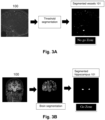
- Fig. 3A shows an example of a 3D X-ray Angiography medical image (depicted only as a 2D plane for simplicity), and some areas of interest 101 from that medical image 100 corresponding to vessels. Hitting a vessel with the preliminary path 110 could provoke bleeding, and thus is a major risk which should be avoided.
- Fig. 3B shows an example of a T1 Magnetic resonance image giving anatomical information of the inside of the brain. With this image some areas of interest 101 can be segmented and the preliminary path 110 should traverse them.
- Different type of projections 130 can be used for executing said step 1006, for example a perspective projection technique, an orthogonal projection technique or a spherical projection technique.
- a perspective projection is used.
- the plurality of rectilinear paths all traverse said first point of the preliminary path 110.
- another perspective projection can be used, see Fig. 4B , but in this latter case with one point on a near clip plane and the other in a far clip plane.
- the paths in this case will have different length.
- the different alternative paths do not cross at the first point P1 of the preliminary path 110, but at another point which lies in the line defined by the first point P1 and the second point P2.
- an orthogonal projection is used.
- an orthographic camera is used.
- the plurality of rectilinear paths now contain paths which are the same length as the preliminary one, and parallel to each other.
- a spherical projection is used. This case is similar to the perspective projection of the first detailed embodiment but yields rectilinear paths which are all the same length.
- Program aspects of the technology may be thought of as "products” or “articles of manufacture” typically in the form of executable code and/or associated data that is carried on or embodied in a type of machine readable medium.
- Tangible non-transitory “storage” type media include any or all of the memory or other storage for the computers, processors, or the like, or associated modules thereof, such as various semiconductor memories, tape drives, disk drives and the like, which may provide storage at any time for the software programming.
- All or portions of the software may at times be communicated through a network such as the Internet or various other telecommunication networks.
- Such communications may enable loading of the software from one computer or processor into another, for example, from a management server or host computer of a scheduling system into the hardware platform(s) of a computing environment or other system implementing a computing environment or similar functionalities in connection with image processing.
- another type of media that may bear the software elements includes optical, electrical and electromagnetic waves, such as used across physical interfaces between local devices, through wired and optical landline networks and over various air-links.
- the physical elements that carry such waves, such as wired or wireless links, optical links or the like, also may be considered as media bearing the software.
- terms such as computer or machine "readable medium” refer to any medium that participates in providing instructions to a processor for execution.
- a machine-readable medium may take many forms, including but not limited to, a tangible storage medium, a carrier wave medium or physical transmission medium.
- Non-volatile storage media include, for example, optical or magnetic disks, such as any of the storage devices in any computer(s), or the like, which may be used to implement the system or any of its components shown in the drawings.
- Volatile storage media may include dynamic memory, such as a main memory of such a computer platform.
- Tangible transmission media may include coaxial cables; copper wire and fiber optics, including the wires that form a bus within a computer system.
- Carrier-wave transmission media may take the form of electric or electromagnetic signals, or acoustic or light waves such as those generated during radio frequency (RF) and infrared (IR) data communications.
- RF radio frequency
- IR infrared
- Computer-readable media may include, for example: a floppy disk, a flexible disk, hard disk, magnetic tape, any other magnetic medium, a CD-ROM, DVD or DVD-ROM, any other optical medium, punch cards paper tape, any other physical storage medium with patterns of holes, a RAM, a PROM and EPROM, a FLASH-EPROM, any other memory chip or cartridge, a carrier wave transporting data or instructions, cables or links transporting such a carrier wave, or any other medium from which a computer may read programming code and/or data. Many of these forms of computer readable media may be involved in carrying one or more sequences of one or more instructions to a physical processor for execution.
Landscapes
- Engineering & Computer Science (AREA)
- Physics & Mathematics (AREA)
- General Physics & Mathematics (AREA)
- Theoretical Computer Science (AREA)
- Computer Vision & Pattern Recognition (AREA)
- General Health & Medical Sciences (AREA)
- Health & Medical Sciences (AREA)
- Medical Informatics (AREA)
- Nuclear Medicine, Radiotherapy & Molecular Imaging (AREA)
- Radiology & Medical Imaging (AREA)
- Quality & Reliability (AREA)
- Computer Graphics (AREA)
- Magnetic Resonance Imaging Apparatus (AREA)
- Apparatus For Radiation Diagnosis (AREA)
Claims (14)
- Computerimplementiertes Verfahren zum Berechnen gleichzeitiger geradliniger Bahnen unter Verwendung medizinischer Bilder, wobei das Verfahren das Durchführen der folgenden Schritte durch einen Prozessor eines Computersystems umfasst:- Empfangen eines medizinischen 3D-Bildes (100), umfassend Voxel, die ein Volumen einer anatomischen Region eines Patienten darstellen, und einer vorläufigen Bahn (110), die durch zwei Punkte, einen ersten Punkt (P1) und einen zweiten Punkt (P2), bestimmt wird, die das das medizinische 3D-Bild (100) durchläuft, wobei das medizinische 3D-Bild (100) darin mindestens einen Bereich von Interesse (101) segmentiert aufweist, und die vorläufige Bahn (110) eine Sicherheitszone (111) mit einem gegebenen Abstand umfasst;- Bereitstellen eines neuen 3D-Bildes durch Berechnen einer Abstandskarte (120) des Bereichs von Interesse (101), wobei das neue 3D-Bild die gleichen Abmessungen wie das medizinische 3D-Bild (100) aufweist und Voxel umfasst, wobei jedes Voxel einen Abstandswert zu dem Bereich von Interesse (101) angibt;- Zuordnen der Voxel, die einen Abstandswert aufweisen, der größer als ein Abstandsschwellenwert ist, zu einem ersten Wert und Zuordnen der Voxel, die einen Abstandswert aufweisen, der gleich dem oder kleiner als der Abstandsschwellenwert ist, zu einem zweiten Wert, wobei der Abstandsschwellenwert gleich dem gegebenen Abstand der Sicherheitszone (111) ist;- Auswählen der Voxel, die den zweiten Wert aufweisen; und- Erhalten eines projizierten 2D-Bildes, das eine Vielzahl geradliniger Bahnen beinhaltet, durch Projizieren (130) der ausgewählten Voxel unter Verwendung eines Kegelstumpfes (131), der die vorläufige Bahn (110) auf einen einzelnen Punkt projiziert,wobei das projizierte 2D-Bild Pixel umfasst, die jeweils einen ersten oder zweiten Wert aufweisen, wobei die Pixel, die den zweiten Wert aufweisen, angeben, dass die geradlinige Bahn das medizinische 3D-Bild in einem Abstand durchläuft, der kleiner oder gleich dem Abstandsschwellenwert von dem Bereich von Interesse (101) ist, und die Pixel, die den ersten Wert aufweisen, angeben, dass die geradlinige Bahn das medizinische 3D-Bild in einem Abstand durchläuft, der größer als der Abstandsschwellenwert von dem Bereich von Interesse (101) ist.
- Verfahren nach Anspruch 1, wobei das Projizieren (130) unter Verwendung einer Perspektivenprojektionstechnik durchgeführt wird, wobei die Vielzahl geradliniger Bahnen alle einen ersten Punkt (P1) der vorläufigen Bahn (110) durchlaufen.
- Verfahren nach Anspruch 1, wobei das Projizieren (130) unter Verwendung einer Perspektivenprojektionstechnik durchgeführt wird, wobei die Vielzahl geradliniger Bahnen alle einen Punkt durchlaufen, der in einer Ebene liegt, die durch den ersten Punkt (P1) der vorläufigen Bahn (110) definiert ist.
- Verfahren nach Anspruch 1, wobei das Projizieren (130) unter Verwendung einer Orthogonalprojektionstechnik durchgeführt wird, wobei die Vielzahl geradliniger Bahnen alle die gleiche Länge wie die vorläufige Bahn (110) aufweisen und parallel zueinander sind.
- Verfahren nach Anspruch 1, wobei das Projizieren (130) unter Verwendung einer sphärischen Projektionstechnik durchgeführt wird, wobei die Vielzahl geradliniger Bahnen alle den ersten Punkt (P1) der vorläufigen Bahn (110) durchlaufen und die gleiche Länge aufweisen.
- Verfahren nach Anspruch 1, wobei eine vordere Clip-Ebene des Kegelstumpfes (131) einen der beiden Punkte (P1, P2) der vorläufigen Bahn (110) enthält und eine hintere Clip-Ebene des Kegelstumpfes (131) den anderen Punkt (P1, P2) der vorläufigen Bahn (110) enthält.
- Verfahren nach einem der vorhergehenden Ansprüche, wobei der mindestens eine Bereich von Interesse (101) eine Go- oder eine No-Go-Zone ist.
- Verfahren nach Anspruch 7, wobei der erste und der zweite Wert Farbwerte sind, wobei der erste Wert eine transparente Farbe und der zweite Wert eine lichtundurchlässige Farbe ist.
- Verfahren nach Anspruch 8, ferner umfassend das Auswählen einer von einer Vielzahl geradliniger Bahnen, wobei die ausgewählte geradlinige Bahn die Bahn ist, die eine transparente Pixelfarbe aufweist, die sich in dem geringsten Abstand von dem Pixel der vorläufigen Bahn (110) befindet.
- Verfahren nach einem der vorhergehenden Ansprüche, wobei die anatomische Region des Patienten das Gehirn ist.
- Verfahren nach einem der vorhergehenden Ansprüche, wobei das medizinische 3D-Bild (100) ein Computertomographie-Bild, CT, ein Magnetresonanzbild, MRI, ein Angiographie-Bild oder ein nuklearmedizinisches Funktionsbild ist, einschließlich eines Positronenemissionstomographie-Bildes, PET.
- System zum Berechnen gleichzeitiger geradliniger Bahnen unter Verwendung medizinischer Bilder, umfassend:einen Prozessor;Software, die auf dem Prozessor zu Folgendem ausführbar ist:- Empfangen eines medizinischen 3D-Bildes (100), umfassend Voxel, die ein Volumen einer anatomischen Region eines Patienten darstellen, und einer vorläufigen Bahn (110), die durch zwei Punkte, einen ersten Punkt (P1) und einen zweiten Punkt (P2), bestimmt wird, die das das medizinische 3D-Bild (100) durchläuft, wobei das medizinische 3D-Bild (100) darin mindestens einen Bereich von Interesse (101) segmentiert aufweist und wobei die vorläufige Bahn (110) eine Sicherheitszone (111) mit einem gegebenen Abstand umfasst;- Bereitstellen eines neuen 3D-Bildes durch Berechnen einer Abstandskarte (120) des Bereichs von Interesse (101), wobei das neue 3D-Bild die gleichen Abmessungen wie das medizinische 3D-Bild (100) aufweist und Voxel umfasst, wobei jedes Voxel einen Abstandswert zu dem Bereich von Interesse (101) angibt;- Zuordnen der Voxel, die einen Abstandswert aufweisen, der größer als ein Abstandsschwellenwert ist, zu einem ersten Wert und Zuordnen der Voxel, die einen Abstandswert aufweisen, der gleich dem oder kleiner als der Abstandsschwellenwert ist, zu einem zweiten Wert, wobei der Abstandsschwellenwert gleich dem gegebenen Abstand der Sicherheitszone (111) ist;- Auswählen der Voxel, die den zweiten Wert aufweisen; und- Erhalten eines projizierten 2D-Bildes, das eine Vielzahl geradliniger Bahnen beinhaltet, durch Projizieren (130) der ausgewählten Voxel unter Verwendung eines Kegelstumpfes (131), der die vorläufige Bahn (110) auf einen einzelnen Punkt projiziert,wobei das projizierte 2D-Bild Pixel umfasst, die jeweils einen ersten oder zweiten Wert aufweisen, wobei die Pixel, die den zweiten Wert aufweisen, angeben, dass die geradlinige Bahn das medizinische 3D-Bild in einem Abstand durchläuft, der kleiner oder gleich dem Abstandsschwellenwert von dem Bereich von Interesse (101) ist, und die Pixel, die den ersten Wert aufweisen, angeben, dass die geradlinige Bahn das medizinische 3D-Bild in einem Abstand durchläuft, der größer als der Abstandsschwellenwert von dem Bereich von Interesse (101) ist.
- System nach Anspruch 12, wobei der mindestens eine Bereich von Interesse (101) eine Go- oder eine No-Go-Zone ist und wobei der erste und der zweite Wert Farbwerte sind, wobei der erste Farbwert eine transparente Farbe und der zweite Farbwert eine lichtundurchlässige Farbe ist, und wobei die Software ferner eine von einer Vielzahl geradliniger Bahnen auswählt, indem sie die Bahn auswählt, die eine transparente Pixelfarbe aufweist, die der vorläufigen Bahn (110) ähnlicher ist.
- Nichttransitorisches computerlesbares Medium, das Code-Anweisungen beinhaltet, die bei Ausführung in einem Computersystem die Schritte des Verfahrens nach einem der vorhergehenden Ansprüche 1 bis 11 implementieren.
Priority Applications (3)
| Application Number | Priority Date | Filing Date | Title |
|---|---|---|---|
| EP19382502.3A EP3754606B1 (de) | 2019-06-17 | 2019-06-17 | Computerimplementiertes verfahren, system und computerprogramme zum berechnen gleichzeitiger geradliniger bahnen unter verwendung medizinischer bilder |
| ES19382502T ES3015162T3 (en) | 2019-06-17 | 2019-06-17 | A computer implemented method, a system and computer programs for computing simultaneous rectilinear paths using medical images |
| US16/902,912 US11282263B2 (en) | 2019-06-17 | 2020-06-16 | Computer implemented method, a system and computer programs for computing simultaneous rectilinear paths using medical images |
Applications Claiming Priority (1)
| Application Number | Priority Date | Filing Date | Title |
|---|---|---|---|
| EP19382502.3A EP3754606B1 (de) | 2019-06-17 | 2019-06-17 | Computerimplementiertes verfahren, system und computerprogramme zum berechnen gleichzeitiger geradliniger bahnen unter verwendung medizinischer bilder |
Publications (3)
| Publication Number | Publication Date |
|---|---|
| EP3754606A1 EP3754606A1 (de) | 2020-12-23 |
| EP3754606C0 EP3754606C0 (de) | 2024-12-25 |
| EP3754606B1 true EP3754606B1 (de) | 2024-12-25 |
Family
ID=67003426
Family Applications (1)
| Application Number | Title | Priority Date | Filing Date |
|---|---|---|---|
| EP19382502.3A Active EP3754606B1 (de) | 2019-06-17 | 2019-06-17 | Computerimplementiertes verfahren, system und computerprogramme zum berechnen gleichzeitiger geradliniger bahnen unter verwendung medizinischer bilder |
Country Status (3)
| Country | Link |
|---|---|
| US (1) | US11282263B2 (de) |
| EP (1) | EP3754606B1 (de) |
| ES (1) | ES3015162T3 (de) |
Families Citing this family (2)
| Publication number | Priority date | Publication date | Assignee | Title |
|---|---|---|---|---|
| EP4318393A4 (de) * | 2021-04-23 | 2025-01-08 | Wuhan United Imaging Healthcare Surgical Technology Co., Ltd. | Chirurgisches wegverarbeitungssystem, verfahren, gerät und vorrichtung sowie speichermedium |
| CN114638962A (zh) * | 2022-03-29 | 2022-06-17 | 联影智能医疗科技(成都)有限公司 | 一种对医学成像中的感兴趣区域进行标注的方法和系统 |
Family Cites Families (10)
| Publication number | Priority date | Publication date | Assignee | Title |
|---|---|---|---|---|
| US8385971B2 (en) * | 2008-08-19 | 2013-02-26 | Digimarc Corporation | Methods and systems for content processing |
| US8641621B2 (en) * | 2009-02-17 | 2014-02-04 | Inneroptic Technology, Inc. | Systems, methods, apparatuses, and computer-readable media for image management in image-guided medical procedures |
| US20130278631A1 (en) * | 2010-02-28 | 2013-10-24 | Osterhout Group, Inc. | 3d positioning of augmented reality information |
| GB201012519D0 (en) * | 2010-07-26 | 2010-09-08 | Ucl Business Plc | Method and system for anomaly detection in data sets |
| WO2012092511A2 (en) | 2010-12-29 | 2012-07-05 | The Ohio State University | Automated trajectory planning for stereotactic procedures |
| WO2013116240A1 (en) * | 2012-01-30 | 2013-08-08 | Inneroptic Technology, Inc. | Multiple medical device guidance |
| WO2015099427A1 (ko) | 2013-12-23 | 2015-07-02 | 재단법인 아산사회복지재단 | 의료용 바늘의 삽입 경로의 생성 방법 |
| US9901406B2 (en) * | 2014-10-02 | 2018-02-27 | Inneroptic Technology, Inc. | Affected region display associated with a medical device |
| KR101758741B1 (ko) * | 2015-09-09 | 2017-08-11 | 울산대학교 산학협력단 | 의료영상을 사용하는 중재시술 가이드 방법 및 이를 위한 중재시술 시스템 |
| GB201616283D0 (en) | 2016-09-26 | 2016-11-09 | Ucl Business Plc | A system and method for computer assisted planning of a trajectory for a surgical insertion into a skull |
-
2019
- 2019-06-17 EP EP19382502.3A patent/EP3754606B1/de active Active
- 2019-06-17 ES ES19382502T patent/ES3015162T3/es active Active
-
2020
- 2020-06-16 US US16/902,912 patent/US11282263B2/en active Active
Also Published As
| Publication number | Publication date |
|---|---|
| EP3754606C0 (de) | 2024-12-25 |
| US11282263B2 (en) | 2022-03-22 |
| EP3754606A1 (de) | 2020-12-23 |
| US20200394833A1 (en) | 2020-12-17 |
| ES3015162T3 (en) | 2025-04-29 |
Similar Documents
| Publication | Publication Date | Title |
|---|---|---|
| EP3142589B1 (de) | System und verfahren zum rechnergestützten planung von trajektorien für ein chirurgisches einsetzen in einen schädel | |
| EP3516629B1 (de) | System und verfahren zur computerunterstützten planung einer trajektorie für einen chirurgischen eingriff in einen schädel | |
| EP2810598B1 (de) | Chirurgische hilfsvorrichtung, chirurgisches hilfsverfahren und chirurgisches hilfsprogramm | |
| US10049467B2 (en) | Apparatus and method for reconstructing medical image | |
| US10524823B2 (en) | Surgery assistance apparatus, method and program | |
| US7773786B2 (en) | Method and apparatus for three-dimensional interactive tools for semi-automatic segmentation and editing of image objects | |
| EP3025303B1 (de) | Multimodale segmentierung von bilddaten | |
| EP4132405B1 (de) | Rasterschablonenpositionierung in der interventionellen medizin | |
| US12141966B2 (en) | AI-based atlas mapping slice localizer for deep learning autosegmentation | |
| US9489736B2 (en) | Visualization of image transformation | |
| US11282263B2 (en) | Computer implemented method, a system and computer programs for computing simultaneous rectilinear paths using medical images | |
| Cao et al. | Automated catheter detection in volumetric ultrasound | |
| US11423553B2 (en) | Calibration of image-registration based tracking procedures | |
| CN119136880A (zh) | 用于量化放射治疗中患者设置误差的方法 | |
| Avrunin | Ismail Saied H F.“Planning Method for Safety Neurosurgical and Computed Tomography Contrast-Data Set Visualization” | |
| EP4345747A1 (de) | Verfahren zur verarbeitung medizinischer bilddaten | |
| CN110428489B (zh) | 弧形通道规划方法及装置 | |
| WO2010079394A1 (en) | Concurrent multiple model segmentation with collision detection | |
| Šušteršič et al. | Application of active contours method in assessment of optimal approach trajectory to brain tumor | |
| Аврунін et al. | Planning Method for Safety Neurosurgical and Computed Tomography Contrast-Data Set Visualization |
Legal Events
| Date | Code | Title | Description |
|---|---|---|---|
| PUAI | Public reference made under article 153(3) epc to a published international application that has entered the european phase |
Free format text: ORIGINAL CODE: 0009012 |
|
| STAA | Information on the status of an ep patent application or granted ep patent |
Free format text: STATUS: THE APPLICATION HAS BEEN PUBLISHED |
|
| AK | Designated contracting states |
Kind code of ref document: A1 Designated state(s): AL AT BE BG CH CY CZ DE DK EE ES FI FR GB GR HR HU IE IS IT LI LT LU LV MC MK MT NL NO PL PT RO RS SE SI SK SM TR |
|
| AX | Request for extension of the european patent |
Extension state: BA ME |
|
| STAA | Information on the status of an ep patent application or granted ep patent |
Free format text: STATUS: REQUEST FOR EXAMINATION WAS MADE |
|
| 17P | Request for examination filed |
Effective date: 20210505 |
|
| RBV | Designated contracting states (corrected) |
Designated state(s): AL AT BE BG CH CY CZ DE DK EE ES FI FR GB GR HR HU IE IS IT LI LT LU LV MC MK MT NL NO PL PT RO RS SE SI SK SM TR |
|
| GRAP | Despatch of communication of intention to grant a patent |
Free format text: ORIGINAL CODE: EPIDOSNIGR1 |
|
| STAA | Information on the status of an ep patent application or granted ep patent |
Free format text: STATUS: GRANT OF PATENT IS INTENDED |
|
| INTG | Intention to grant announced |
Effective date: 20241014 |
|
| GRAS | Grant fee paid |
Free format text: ORIGINAL CODE: EPIDOSNIGR3 |
|
| GRAA | (expected) grant |
Free format text: ORIGINAL CODE: 0009210 |
|
| STAA | Information on the status of an ep patent application or granted ep patent |
Free format text: STATUS: THE PATENT HAS BEEN GRANTED |
|
| AK | Designated contracting states |
Kind code of ref document: B1 Designated state(s): AL AT BE BG CH CY CZ DE DK EE ES FI FR GB GR HR HU IE IS IT LI LT LU LV MC MK MT NL NO PL PT RO RS SE SI SK SM TR |
|
| REG | Reference to a national code |
Ref country code: GB Ref legal event code: FG4D |
|
| REG | Reference to a national code |
Ref country code: CH Ref legal event code: EP |
|
| REG | Reference to a national code |
Ref country code: DE Ref legal event code: R096 Ref document number: 602019063906 Country of ref document: DE |
|
| REG | Reference to a national code |
Ref country code: IE Ref legal event code: FG4D |
|
| U01 | Request for unitary effect filed |
Effective date: 20250121 |
|
| U07 | Unitary effect registered |
Designated state(s): AT BE BG DE DK EE FI FR IT LT LU LV MT NL PT RO SE SI Effective date: 20250127 |
|
| PG25 | Lapsed in a contracting state [announced via postgrant information from national office to epo] |
Ref country code: NO Free format text: LAPSE BECAUSE OF FAILURE TO SUBMIT A TRANSLATION OF THE DESCRIPTION OR TO PAY THE FEE WITHIN THE PRESCRIBED TIME-LIMIT Effective date: 20250325 |
|
| PG25 | Lapsed in a contracting state [announced via postgrant information from national office to epo] |
Ref country code: GR Free format text: LAPSE BECAUSE OF FAILURE TO SUBMIT A TRANSLATION OF THE DESCRIPTION OR TO PAY THE FEE WITHIN THE PRESCRIBED TIME-LIMIT Effective date: 20250326 |
|
| PG25 | Lapsed in a contracting state [announced via postgrant information from national office to epo] |
Ref country code: RS Free format text: LAPSE BECAUSE OF FAILURE TO SUBMIT A TRANSLATION OF THE DESCRIPTION OR TO PAY THE FEE WITHIN THE PRESCRIBED TIME-LIMIT Effective date: 20250325 |
|
| REG | Reference to a national code |
Ref country code: ES Ref legal event code: FG2A Ref document number: 3015162 Country of ref document: ES Kind code of ref document: T3 Effective date: 20250429 |
|
| PG25 | Lapsed in a contracting state [announced via postgrant information from national office to epo] |
Ref country code: SM Free format text: LAPSE BECAUSE OF FAILURE TO SUBMIT A TRANSLATION OF THE DESCRIPTION OR TO PAY THE FEE WITHIN THE PRESCRIBED TIME-LIMIT Effective date: 20241225 |
|
| PG25 | Lapsed in a contracting state [announced via postgrant information from national office to epo] |
Ref country code: PL Free format text: LAPSE BECAUSE OF FAILURE TO SUBMIT A TRANSLATION OF THE DESCRIPTION OR TO PAY THE FEE WITHIN THE PRESCRIBED TIME-LIMIT Effective date: 20241225 |
|
| PGFP | Annual fee paid to national office [announced via postgrant information from national office to epo] |
Ref country code: GB Payment date: 20250626 Year of fee payment: 7 |
|
| PG25 | Lapsed in a contracting state [announced via postgrant information from national office to epo] |
Ref country code: IS Free format text: LAPSE BECAUSE OF FAILURE TO SUBMIT A TRANSLATION OF THE DESCRIPTION OR TO PAY THE FEE WITHIN THE PRESCRIBED TIME-LIMIT Effective date: 20250425 |
|
| U20 | Renewal fee for the european patent with unitary effect paid |
Year of fee payment: 7 Effective date: 20250617 |
|
| PG25 | Lapsed in a contracting state [announced via postgrant information from national office to epo] |
Ref country code: SK Free format text: LAPSE BECAUSE OF FAILURE TO SUBMIT A TRANSLATION OF THE DESCRIPTION OR TO PAY THE FEE WITHIN THE PRESCRIBED TIME-LIMIT Effective date: 20241225 |
|
| PG25 | Lapsed in a contracting state [announced via postgrant information from national office to epo] |
Ref country code: CZ Free format text: LAPSE BECAUSE OF FAILURE TO SUBMIT A TRANSLATION OF THE DESCRIPTION OR TO PAY THE FEE WITHIN THE PRESCRIBED TIME-LIMIT Effective date: 20241225 |
|
| PGFP | Annual fee paid to national office [announced via postgrant information from national office to epo] |
Ref country code: ES Payment date: 20250710 Year of fee payment: 7 |
|
| PLBE | No opposition filed within time limit |
Free format text: ORIGINAL CODE: 0009261 |
|
| STAA | Information on the status of an ep patent application or granted ep patent |
Free format text: STATUS: NO OPPOSITION FILED WITHIN TIME LIMIT |
|
| REG | Reference to a national code |
Ref country code: CH Ref legal event code: L10 Free format text: ST27 STATUS EVENT CODE: U-0-0-L10-L00 (AS PROVIDED BY THE NATIONAL OFFICE) Effective date: 20251105 |
|
| 26N | No opposition filed |
Effective date: 20250926 |
|
| REG | Reference to a national code |
Ref country code: CH Ref legal event code: H13 Free format text: ST27 STATUS EVENT CODE: U-0-0-H10-H13 (AS PROVIDED BY THE NATIONAL OFFICE) Effective date: 20260127 |
|
| PG25 | Lapsed in a contracting state [announced via postgrant information from national office to epo] |
Ref country code: MC Free format text: LAPSE BECAUSE OF FAILURE TO SUBMIT A TRANSLATION OF THE DESCRIPTION OR TO PAY THE FEE WITHIN THE PRESCRIBED TIME-LIMIT Effective date: 20241225 |