EP3754590A1 - Image enhancement method, data processing device, and storage medium - Google Patents
Image enhancement method, data processing device, and storage medium Download PDFInfo
- Publication number
- EP3754590A1 EP3754590A1 EP19754702.9A EP19754702A EP3754590A1 EP 3754590 A1 EP3754590 A1 EP 3754590A1 EP 19754702 A EP19754702 A EP 19754702A EP 3754590 A1 EP3754590 A1 EP 3754590A1
- Authority
- EP
- European Patent Office
- Prior art keywords
- window
- image
- determining
- representing
- processed image
- Prior art date
- Legal status (The legal status is an assumption and is not a legal conclusion. Google has not performed a legal analysis and makes no representation as to the accuracy of the status listed.)
- Granted
Links
Images








Classifications
-
- G—PHYSICS
- G06—COMPUTING OR CALCULATING; COUNTING
- G06T—IMAGE DATA PROCESSING OR GENERATION, IN GENERAL
- G06T5/00—Image enhancement or restoration
- G06T5/70—Denoising; Smoothing
-
- G—PHYSICS
- G06—COMPUTING OR CALCULATING; COUNTING
- G06T—IMAGE DATA PROCESSING OR GENERATION, IN GENERAL
- G06T5/00—Image enhancement or restoration
- G06T5/73—Deblurring; Sharpening
-
- G—PHYSICS
- G06—COMPUTING OR CALCULATING; COUNTING
- G06T—IMAGE DATA PROCESSING OR GENERATION, IN GENERAL
- G06T5/00—Image enhancement or restoration
- G06T5/50—Image enhancement or restoration using two or more images, e.g. averaging or subtraction
-
- G—PHYSICS
- G06—COMPUTING OR CALCULATING; COUNTING
- G06T—IMAGE DATA PROCESSING OR GENERATION, IN GENERAL
- G06T5/00—Image enhancement or restoration
- G06T5/90—Dynamic range modification of images or parts thereof
- G06T5/92—Dynamic range modification of images or parts thereof based on global image properties
-
- G—PHYSICS
- G06—COMPUTING OR CALCULATING; COUNTING
- G06T—IMAGE DATA PROCESSING OR GENERATION, IN GENERAL
- G06T2207/00—Indexing scheme for image analysis or image enhancement
- G06T2207/10—Image acquisition modality
- G06T2207/10016—Video; Image sequence
-
- G—PHYSICS
- G06—COMPUTING OR CALCULATING; COUNTING
- G06T—IMAGE DATA PROCESSING OR GENERATION, IN GENERAL
- G06T2207/00—Indexing scheme for image analysis or image enhancement
- G06T2207/10—Image acquisition modality
- G06T2207/10024—Color image
-
- G—PHYSICS
- G06—COMPUTING OR CALCULATING; COUNTING
- G06T—IMAGE DATA PROCESSING OR GENERATION, IN GENERAL
- G06T2207/00—Indexing scheme for image analysis or image enhancement
- G06T2207/20—Special algorithmic details
- G06T2207/20076—Probabilistic image processing
-
- G—PHYSICS
- G06—COMPUTING OR CALCULATING; COUNTING
- G06T—IMAGE DATA PROCESSING OR GENERATION, IN GENERAL
- G06T2207/00—Indexing scheme for image analysis or image enhancement
- G06T2207/20—Special algorithmic details
- G06T2207/20172—Image enhancement details
- G06T2207/20192—Edge enhancement; Edge preservation
-
- G—PHYSICS
- G06—COMPUTING OR CALCULATING; COUNTING
- G06T—IMAGE DATA PROCESSING OR GENERATION, IN GENERAL
- G06T2207/00—Indexing scheme for image analysis or image enhancement
- G06T2207/20—Special algorithmic details
- G06T2207/20212—Image combination
- G06T2207/20224—Image subtraction
Definitions
- This disclosure relates to the field of image processing technologies, and in particular, to an image enhancement method, a data processing device, and a storage medium.
- image enhancement may be performed on an image frame sequence in a video in some application scenarios.
- some image processing applications may use smooth filtering or the like for image enhancement.
- the related art technologies for image enhancement need to improve an image enhancement effect.
- This disclosure provides an image enhancement solution to improve an image enhancement effect.
- an image enhancement method including: performing edge-preserving filtering on an original image to obtain a first processed image; obtaining a detail feature of the original image; determining a second processed image according to the detail feature and the first processed image; and processing the second processed image in a guidance image filtering manner by using the original image as a guidance image to obtain a third processed image.
- an image enhancement apparatus including: a first smoothing unit configured to perform edge-preserving filtering on an original image to obtain a first processed image; a detail obtaining unit configured to obtain a detail feature of the original image; an image superimposing unit configured to determine a second processed image according to the detail feature and the first processed image; and an image enhancement unit configured to process the second processed image in a guidance image filtering manner by using the original image as a guidance image to obtain a third processed image.
- a video service system including the image enhancement apparatus according to this disclosure.
- a terminal device including the image enhancement apparatus according to this disclosure.
- a data processing device including: one or more processors, a memory, and one or more programs.
- One or more programs are stored in the memory and are configured to be executed by the one or more processors, the one or more programs including an instruction for performing the image enhancement method according to this disclosure.
- a storage medium storing one or more programs
- the one or more programs including an instruction, the instruction, when executed by a data processing device, causing the data processing device to perform the image enhancement method according to this disclosure.
- the third processed image with a high smoothness degree and an enhanced detail feature can be obtained.
- a noise reduction degree of an image is improved and a detail feature is enhanced, so that pictures are clearer, overall brightness is more uniform, a sense of layering is stronger, a contrast is higher, and colors are more vivid.
- FIG. 1A is a schematic diagram of an application scenario according to some embodiments of this disclosure.
- the application scenario includes a terminal device 110 and a video service system 120.
- the terminal device 110 may be, for example, various devices such as a desktop computer, a mobile phone, a tablet computer, a smart television (TV), or a laptop computer.
- the terminal device 110 may include a video application 111.
- the terminal device 110 may download and install the video application 111.
- the video application 111 may be alternatively pre-installed in the terminal device 110.
- the video service system 120 may include, for example, one or more servers. In some embodiments, the video service system 120 may store video content.
- the video application 111 may obtain the video content from the video service system 120 through a network 130.
- the video application 111 may perform video enhancement on the video content from the local or from the video service system 120.
- the video application 111 may be, for example, various applications that include a video play function such as a video play client (for example, a Tencent video client or an iQiyi video client), a social application, or a browser. These are merely examples and the disclosure is not limited thereto.
- FIG. 1B is a schematic diagram of an application scenario according to some embodiments of this disclosure.
- the application scenario includes a terminal device 140 and a video service system 150.
- the video service system 150 may include a video processing application 151.
- the video processing application 151 may perform image enhancement on a video.
- the terminal device 140 may include a video play application 141.
- the video play application 141 is, for example, various applications including a video play function such as a video play client, a social application, or a browser.
- the video play application 141 may obtain and play back an image-enhanced video from the video service system 150.
- both the terminal device 110 and the video service system 150 may be used to enhance a video.
- various devices for video enhancement may perform image enhancement on each image frame in a video. An image enhancement manner according to this disclosure is described in detail below with reference to FIG. 2 .
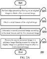
- FIG. 2A is a flowchart of an image enhancement method 200 according to some embodiments of this disclosure.
- the image enhancement method 200 is performed by, for example, a data processing device such as a terminal device 110 or a video service system 150.
- the image enhancement method 200 may include step S201: edge-preserving filtering is performed on an original image to obtain a first processed image.
- the original image is processed in a guidance image filtering manner by using the original image as a guidance image to obtain the first processed image.
- various edge-preserving filtering manners such as median filtering, bilateral filtering, or weighted least square filtering may be used.
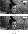
- FIG. 2B and FIG. 2C respectively show the original image and the first processed image in some embodiments.
- the first processed image has a higher smoothness degree than the original image.
- a detail feature of the original image is obtained.
- the detail feature may include, for example, an edge feature and a texture feature.
- a color difference between the original image and the first processed image may be first determined, and then the detail feature is determined according to the color difference.
- a difference between the original image and the first processed image on one or more color channels may be determined, and the difference on the one or more color channels is determined as the color difference.
- step S202 when the original image is a grayscale image, in step S202, a grayscale value difference between the original image and the first processed image may be determined, and the grayscale value is determined as the color difference.
- the original image may include a plurality of color channels.
- a difference between the original image and the first processed image on the plurality of color channels may be determined, and the difference is determined as the color difference.
- the original image is in a red, green and blue (RGB) format.
- the color difference obtained in step S202 may include a difference of a red channel, a difference of a green channel, and a difference of a blue channel.
- the color difference determined in step S202 may include, for example, feature information such as an edge and a texture in the original image.
- the detail feature of the original image may be determined according to the color difference in step S202.
- the color difference may be directly used as the detail feature in step S202.
- the color difference may be enhanced according to an adjustment coefficient to obtain an enhanced color difference, and the enhanced color difference is determined as the detail feature corresponding to the original image.
- the detail feature of the original image may be obtained in other manners in step S202.
- step S203 may be performed in the image enhancement method 200.
- a second processed image is determined according to the detail feature and the first processed image.
- the detail feature may be superimposed on the first processed image to obtain the second processed image.
- the second processed image may be determined by using the detail feature and the first processed image in other manners in step S203.
- the second processed image is determined by using the detail feature and the first processed image in step S203, so that the second processed image can maintain a smoothness degree (or a noise reduction degree) close to the first processed image, and the second processed image can have an enhanced detail feature.
- details of the second processed image are easier to distinguish than in the first processed image.
- FIG. 2D shows the second processed image obtained through processing in step S202 on the first processed image in FIG. 2C . In comparison with FIG. 2C , details of the second processed image in FIG. 2D are easier to distinguish.
- step S204 the second processed image is processed in the guidance image filtering manner by using the original image as a guidance image to obtain a third processed image.
- noise reduction may be performed on the second processed image in step S204, to improve a noise reduction degree of the third processed image.
- the original image is used as a guidance image, and when smoothing processing is performed on the second processed image in step S204, a detail feature of the second processed image may be retained according to the detail feature of the original image.
- image enhancement is performed on the second processed image by using the original image as a guidance image in step S204, so that a detail feature of the third processed image can be more consistent with an overall overview of the original image.
- FIG. 2E shows the third processed image corresponding to the second processed image in FIG. 2D .
- FIG. 2F is a diagram of comparison between a zone Z2 in FIG. 2E and Z1 in FIG. 2B .
- Content of the zone Z1 is the same as content of the zone Z2.
- Z2 representing the third processed image has a clearer picture, more uniform overall brightness, a stronger sense of layering, and a higher contrast.
- FIG. 2D and FIG. 2F are displayed as grayscale images, which may be actually color images.
- the colored third processed image can be more vivid in step S204.
- the third processed image with a high smoothness degree and an enhanced detail feature can be obtained through a combination of the foregoing steps.
- a noise reduction degree of an image is improved and a detail feature is enhanced, so that a picture become clearer, overall brightness is more uniform, a sense of layering is stronger, a contrast is higher, and colors are more vivid. If a contrast is higher, a color level of an image is higher, and a picture is fuller.
- adaptive processing of image content can be achieved through a combination of the foregoing steps, thereby improving robustness of image processing.
- brightness of the third processed image can be more uniform in the guidance image filtering manner.
- the guidance image filtering manner in step S201 and step S204 may be: performing filtering processing on each color channel (for example, RGB).
- a result of the filtering processing is a result of superimposing a processing result of each color channel.
- the processing process of step S204 is used as an example to further describe guidance image filtering below.
- FIG. 3 is a flowchart of a method 300 for obtaining a third processed image according to some embodiments of this disclosure.
- the pixel in the guidance image is referred to as a first pixel
- the pixel in the second processed image is referred to as a second pixel
- the pixel in the third processed image is referred to as a third pixel in this embodiment.
- the method 300 for obtaining the third processed image may include step S301: a first linear relationship between each first window including the first pixel and a second window at a corresponding position in the third processed image is determined for each first pixel in the guidance image.
- a first linear relationship corresponding to any first window is used to describe a linear relationship between each first pixel in the first window and a pixel at a corresponding position in a corresponding second window.
- Both a size of each first window and a size of the second window at the corresponding position are a first size.
- the first size is used to describe a side length of a window.
- the first size may also be represented by a radius. For example, if the radius is r, the first size may be expressed as (2r+1).
- a window satisfying the first size may include (2r+1) ⁇ (2r+1) pixels.
- the slope of the first linear relationship may be determined by using a method 400 in step S301.
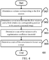
- FIG. 4 is a flowchart of a method 400 for determining a slope of a first linear relationship according to some embodiments of this disclosure.
- step S401 a variance corresponding to the first window is determined.
- step S402 a covariance between the first window and a third window at a corresponding position in the second processed image is determined.
- step S403 a sum of the variance and a regularization coefficient threshold is determined.
- the regularization coefficient threshold is a very small positive number.
- step S404 a ratio of the covariance obtained in step S402 to the sum obtained in step S403 is determined as the slope.
- the slope of the first linear relationship may be determined by using a method 500 in step S301.
- FIG. 5 is a flowchart of a method 500 for determining a slope of a first linear relationship according to some embodiments of this disclosure.
- a variance corresponding to the first window is determined.
- the variance corresponding to the first window is a variance of color information of all pixels in the first window.
- step S502 a covariance between the first window and a third window at a corresponding position in the second processed image is determined.
- step S503 a weight value of a detail feature of the first window in the first processed image is determined.
- step S503 may be implemented as a method 600.
- FIG. 6 is a flowchart of a weight value determining method 600 according to some embodiments of this disclosure.
- step S601 a first variance corresponding to each first pixel in the guidance image and a corresponding second variance are determined.
- a first variance corresponding to one first pixel represents a variance corresponding to a window using the first pixel as a center and satisfying a second size.
- a second variance corresponding to one first pixel represents a variance corresponding to a window using the first pixel as a center and satisfying the first size.
- the second size may represent a minimum window size used in an image processing process, for example, 3, that is, the radius is 1, but is not limited thereto.
- step S602 a product of a first variance corresponding to a center point of the first window and a corresponding second variance is determined, and the one-half power of the product is determined as a third value.
- step S603 a product of the first variance corresponding to each first pixel in the guidance image and the corresponding second variance is determined, and an average value of the one-half power of a product corresponding to each first pixel is determined as a fourth value.
- step S604 a ratio of the third value to the fourth value is determined as the weight value.
- step S504 a first ratio of the regularization coefficient threshold to the weight value is determined.
- step S505 a sum of the covariance in step S502 and the first ratio in step S504 is determined as a first value, a sum of the variance in step S502 and the first ratio in step S504 is determined as a second value, and a ratio of the first value to the second value is determined as the to-be-determined slope.
- the weight value is determined by using the second variance (a variance of a color value within a window satisfying the second size) and the slope is determined by using the weight value.
- the third processed image when the third processed image is obtained by using a second linear relationship related to the slope, the third processed image can always retain a strongest detail feature in the original image.
- the strongest detail feature in the original image can be always retained.
- r 1 2 ⁇ ⁇ k
- r n 2 1 w I ⁇ i ⁇ I ⁇ i
- r 1 2 ⁇ ⁇ i
- r n 2 , wherein n representing a window radius of the first window, ⁇ k
- r n 2 representing the color value variance of all the pixels in the first window, ⁇ k
- r 1 2 representing a color value variance of all pixels in a window using the pixel k as a center and whose radius is 1, ⁇ i
- r 1 2 representing a color value variance of all pixels in a window using the i th pixel in the first window as a center and whose radius is 1, ⁇ i
- r n 2 representing a color value variance of all pixels in a window using the pixel k as a center and whose radius is 1, I representing the guidance image, and
- intercept of the first linear relationship may be determined according to the slope.
- a second linear relationship corresponding to the first pixel is determined according to the first linear relationship corresponding to each first window.
- the second linear relationship is used to describe a linear relationship between the first pixel and a pixel at a corresponding position in the third processed image.
- a slope of the second linear relationship is an average value of a slope of a first linear relationship corresponding to each first window.
- a color value of each pixel in the third processed image is determined according to the color value of each first pixel in the guidance image and the second linear relationship corresponding to each first pixel. Accordingly, the third processed image is obtained.
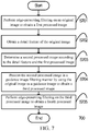
- FIG. 7 is a flowchart of an image enhancement method 700 according to some embodiments of this disclosure.
- the image enhancement method 700 may be performed by, for example, a data processing device such as a terminal device 110 or a video service system 150.
- the image enhancement method 700 may include step S701 to step S704. Implementations of step S701 to step S704 are the same as those of step S201 to step S204, and details are not described herein again.
- the image enhancement method 700 may further include step S705: edge-preserving filtering is performed on the third processed image to obtain a fourth processed image.
- step S705 the third processed image is processed in a guidance image filtering manner by using the third processed image as a guidance image to obtain the fourth processed image.
- edge-preserving filtering is performed by using the third processed image as a guidance image in step S705, so that a noise reduction degree can be further improved, thereby enhancing an image enhancement effect.
- FIG. 8 is a schematic diagram of an image enhancement apparatus 800 according to some embodiments of this disclosure.
- a data processing device such as a terminal device 110 or a video service system 150 may include the image enhancement apparatus 800.
- the image enhancement apparatus 800 may include a first smoothing unit 801, a detail obtaining unit 802, an image superimposing unit 803, and an image enhancement unit 804.
- the first smoothing unit 801 is configured to perform edge-preserving filtering on an original image to obtain a first processed image.
- the first smoothing unit 801 processes the original image in a guidance image filtering manner by using the original image as a guidance image to obtain the first processed image.
- the detail obtaining unit 802 is configured to obtain a detail feature of the original image.
- the detail obtaining unit 802 may determine a color difference between the original image and the first processed image, and determine the detail feature according to the color difference. In some embodiments, the detail obtaining unit 802 may determine a difference between the original image and the first processed image on one or more color channels, and use the difference as the color difference. In some embodiments, the original image is a grayscale image. The detail obtaining unit 802 may determine a grayscale value difference between the original image and the first processed image, and use the grayscale value difference as the color difference. In some other embodiments, the detail obtaining unit 802 may enhance the color difference according to an adjustment coefficient to obtain an enhanced color difference, and use the enhanced color difference as the detail feature. In some other embodiments, the detail obtaining unit 802 may use the color difference as the detail feature.
- the image superimposing unit 803 is configured to determine a second processed image according to the detail feature and the first processed image.
- the image enhancement unit 804 processes the second processed image in a guidance image filtering manner by using the original image as a guidance image to obtain a third processed image.
- the image enhancement unit 804 may determine, for each first pixel in the guidance image, a first linear relationship between each first window including the first pixel and a second window at a corresponding position in the third processed image. Both a size of each first window and a size of the second window at the corresponding position are a first size.
- the image enhancement unit 804 may determine a variance corresponding to the first window. Based on this, the image enhancement unit 804 may determine a sum of the variance and a regularization coefficient threshold. In addition, the image enhancement unit 804 may further determine a covariance between the first window and a third window at a corresponding position in the second processed image. In this way, the image enhancement unit 804 may determine a ratio of the covariance to the sum as a slope of the first linear relationship corresponding to the first window.
- the image enhancement unit 804 may determine a variance corresponding to the first window.
- the image enhancement unit 804 may determine a covariance between the first window and a second window at a corresponding position in the second processed image.
- the image enhancement unit 804 may determine a weight value of a detail feature of the first window in the first processed image.
- the image enhancement unit 804 may determine a first variance corresponding to each first pixel in the guidance image and a corresponding second variance.
- the first variance represents a variance of a window using the first pixel as a center and satisfying a second size.
- the second variance represents a variance of a window using the first pixel as a center and satisfying the first size. Based on this, the image enhancement unit 804 may determine a product of a first variance corresponding to a center point of the first window and a corresponding second variance, and determine the one-half power of the product as a third value.
- the image enhancement unit 804 may determine a product of the first variance corresponding to each first pixel in the guidance image and the corresponding second variance, and determines an average value of the one-half power of a product corresponding to each first pixel as a fourth value. In this way, the image enhancement unit 804 determines a ratio of the third value to the fourth value as the weight value.
- the image enhancement unit 804 may determine a first ratio of a regularization coefficient threshold to the weight value.
- the image enhancement unit 804 may use a sum of the covariance and the first ratio as a first value, and use a sum of the variance and the first ratio as a second value. In this way, the image enhancement unit 804 may determine a ratio of the first value to the second value as a slope of the first linear relationship corresponding to the first window.
- r 1 2 ⁇ ⁇ k
- r n 2 1 w I ⁇ i ⁇ I ⁇ i
- r 1 2 ⁇ ⁇ i
- r n 2 wherein n representing a window radius of the first window, ⁇ k
- r n 2 representing the color value variance of all the pixels in the first window, ⁇ k
- r 1 2 representing a color value variance of all pixels in a window using the pixel k as a center and whose radius is 1, ⁇ i
- r 1 2 representing a color value variance of all pixels in a window using the i th pixel in the first window as a center and whose radius is 1, ⁇ i
- r n 2 representing a color value variance of all pixels in a window using the pixel k as a center and whose radius is 1, I representing the guidance image, and
- the image enhancement unit 804 may determine a second linear relationship corresponding to the first pixel according to the first linear relationship corresponding to each first window.
- the second linear relationship is used to describe a linear relationship between the first pixel and a pixel at a corresponding position in the third processed image.
- the image enhancement unit 804 may determine a color value of each pixel in the third processed image according to a color value of each first pixel in the guidance image and the second linear relationship corresponding to each first pixel.
- the image enhancement apparatus 800 can obtain a third processed image with a high smoothness degree and an enhanced detail feature.
- a noise reduction degree of an image is improved and a detail feature is enhanced, so that pictures are clearer, overall brightness is more uniform, a sense of layering is stronger, a contrast is higher, and colors are more vivid. If a contrast is higher, a color level of an image is higher, and a picture is fuller.
- the image enhancement apparatus 800 can achieve adaptive processing of image content, thereby improving robustness of image processing.
- brightness of the third processed image can be more uniform in the guidance image filtering manner.
- FIG. 9 is a schematic diagram of an image enhancement apparatus 900 according to some embodiments of this disclosure.
- a data processing device such as a terminal device 110 or a video service system 150 may include the image enhancement apparatus 900.
- the image enhancement apparatus 900 may include a first smoothing unit 901, a detail obtaining unit 902, an image superimposing unit 903, and an image enhancement unit 904.
- implementations of the first smoothing unit 901, the detail obtaining unit 902, the image superimposing unit 903, and the image enhancement unit 904 are consistent with the implementations of the first smoothing unit 801, the detail obtaining unit 802, the image superimposing unit 803, and the image enhancement unit 804, and details are not described herein again.
- the image enhancement apparatus 900 may further include a second smoothing unit 905 configured to perform edge-preserving filtering on the third processed image to obtain a fourth processed image.
- the second smoothing unit 905 processes the third processed image in a guidance image filtering manner by using the third processed image as a guidance image to obtain the fourth processed image. In this way, edge-preserving filtering is performed by using the third processed image as a guidance image, so that the image enhancement apparatus 900 can further improve a noise reduction degree, thereby enhancing an image enhancement effect.
- FIG. 10 shows a structural composition diagram of a data processing device.
- the data processing device may be implemented as a terminal device 110 or a video service system 150.
- the data processing device includes one or more processors (CPU) 1002, a communications module 1004, a memory 1006, a user interface 1010, and a communications bus 1008 for interconnecting these components.
- processors CPU
- communications module 1004
- memory 1006
- user interface 1010 a user interface 1010
- a communications bus 1008 for interconnecting these components.
- the processor 1002 may receive and send data by using the communications module 1004 to implement network communication and/or local communication.
- the user interface 1010 includes one or more output devices 1012, including one or more speakers and/or one or more visualization displays.
- the user interface 1010 further includes one or more input devices 1014.
- the user interface 1010 may, for example, receive an instruction of a remote control, but is not limited thereto.
- the memory 1006 may be a high-speed random access memory such as a DRAM, an SRAM, a DDR RAM, or other random access solid-state memory devices; or a non-volatile memory such as one or more magnetic disk storage devices, optical disc storage devices, flash memory devices, or other non-volatile solid-state memory devices.
- a high-speed random access memory such as a DRAM, an SRAM, a DDR RAM, or other random access solid-state memory devices
- a non-volatile memory such as one or more magnetic disk storage devices, optical disc storage devices, flash memory devices, or other non-volatile solid-state memory devices.
- the memory 1006 stores a set of instructions executable by the processor 1002, including:
- each embodiment of this disclosure may be implemented by a data processing program executed by a data processing device such as a computer.
- a data processing program executed by a data processing device such as a computer.
- the data processing program constitutes this disclosure.
- a data processing program stored in a storage medium is directly read from the storage medium for execution or the program is installed on or replicated to a storage device (such as a hard disk or memory) of a data processing device for execution. Therefore, such a storage medium also constitutes the present invention.
- the storage medium may use any type of recording manner, for example, a paper storage medium (such as paper tape), a magnetic storage medium (such as a floppy disk, a hard disk, and a flash memory), an optical storage medium (such as CD-ROM), and a magneto-optical storage medium (such as MO).
- this disclosure further provides a non-volatile storage medium, which stores a data processing program.
- the data processing program is used for executing any one or part of the embodiments of the foregoing image enhancement method of this disclosure.
- the steps of the method of this disclosure may be implemented not only by the data processing program, but also by hardware, such as a logic gate, a switch, an Application Specific Integrated Circuit (ASIC), a programmable logic controller, and an embedded microcontroller. Therefore, the hardware that may implement the image enhancement method of this disclosure may also constitute this disclosure.
- hardware such as a logic gate, a switch, an Application Specific Integrated Circuit (ASIC), a programmable logic controller, and an embedded microcontroller. Therefore, the hardware that may implement the image enhancement method of this disclosure may also constitute this disclosure.
Landscapes
- Physics & Mathematics (AREA)
- General Physics & Mathematics (AREA)
- Engineering & Computer Science (AREA)
- Theoretical Computer Science (AREA)
- Image Processing (AREA)
Abstract
Description
- This application claims the priority to Chinese patent application No.
201810149722.1 - This disclosure relates to the field of image processing technologies, and in particular, to an image enhancement method, a data processing device, and a storage medium.
- With the development of multimedia technologies, there is a great demand for videos in various fields. In order to provide a high-quality video, image enhancement may be performed on an image frame sequence in a video in some application scenarios. For example, some image processing applications may use smooth filtering or the like for image enhancement. However, the related art technologies for image enhancement need to improve an image enhancement effect.
- This disclosure provides an image enhancement solution to improve an image enhancement effect.
- According to one aspect of this disclosure, an image enhancement method is provided, including: performing edge-preserving filtering on an original image to obtain a first processed image; obtaining a detail feature of the original image; determining a second processed image according to the detail feature and the first processed image; and processing the second processed image in a guidance image filtering manner by using the original image as a guidance image to obtain a third processed image.
- According to another aspect of this disclosure, an image enhancement apparatus is provided, including: a first smoothing unit configured to perform edge-preserving filtering on an original image to obtain a first processed image; a detail obtaining unit configured to obtain a detail feature of the original image; an image superimposing unit configured to determine a second processed image according to the detail feature and the first processed image; and an image enhancement unit configured to process the second processed image in a guidance image filtering manner by using the original image as a guidance image to obtain a third processed image.
- According to another aspect of this disclosure, a video service system is provided, including the image enhancement apparatus according to this disclosure.
- According to another aspect of this disclosure, a terminal device is provided, including the image enhancement apparatus according to this disclosure. According to another aspect of this disclosure, a data processing device is provided, including: one or more processors, a memory, and one or more programs. One or more programs are stored in the memory and are configured to be executed by the one or more processors, the one or more programs including an instruction for performing the image enhancement method according to this disclosure.
- According to another aspect of this disclosure, a storage medium storing one or more programs is provided, the one or more programs including an instruction, the instruction, when executed by a data processing device, causing the data processing device to perform the image enhancement method according to this disclosure.
- In view of the above, according to the image enhancement solution in this disclosure, the third processed image with a high smoothness degree and an enhanced detail feature can be obtained. Herein, in the image enhancement solution, a noise reduction degree of an image is improved and a detail feature is enhanced, so that pictures are clearer, overall brightness is more uniform, a sense of layering is stronger, a contrast is higher, and colors are more vivid.
- To describe the technical solutions in embodiments of this disclosure more clearly, the following briefly describes the accompanying drawings required for describing the embodiments. Apparently, the accompanying drawings in the following description show merely some embodiments of this disclosure, and a person of ordinary skill in the art may derive other drawings from these accompanying drawings without creative efforts.
-
FIG. 1A is a schematic diagram of an application scenario according to some embodiments of this disclosure. -
FIG. 1B is a schematic diagram of an application scenario according to some embodiments of this disclosure. -
FIG. 2A is a flowchart of animage enhancement method 200 according to some embodiments of this disclosure. -
FIG. 2B and FIG. 2C respectively show an original image and a first processed image according to some embodiments of this disclosure. -
FIG. 2D shows a second processed image according to some embodiments of this disclosure. -
FIG. 2E shows a third processed image according to some embodiments of this disclosure. -
FIG. 2F is a diagram of comparison between a zone Z2 inFIG. 2E and Z1 inFIG. 2B . -
FIG. 3 is a flowchart of amethod 300 for obtaining a third processed image according to some embodiments of this disclosure. -
FIG. 4 is a flowchart of amethod 400 for determining a slope of a first linear relationship according to some embodiments of this disclosure. -
FIG. 5 is a flowchart of amethod 500 for determining a slope of a first linear relationship according to some embodiments of this disclosure. -
FIG. 6 is a flowchart of a weightvalue determining method 600 according to some embodiments of this disclosure. -
FIG. 7 is a flowchart of animage enhancement method 700 according to some embodiments of this disclosure. -
FIG. 8 is a schematic diagram of an image enhancement apparatus 800 according to some embodiments of this disclosure. -
FIG. 9 is a schematic diagram of an image enhancement apparatus 900 according to some embodiments of this disclosure. -
FIG. 10 shows a structural composition diagram of a data processing device. - The technical solutions in the embodiments of this disclosure will be clearly and completely described in the following with reference to the accompanying drawings in the embodiments of this disclosure. It is obvious that the embodiments to be described are only some rather than all of the embodiments of this disclosure. All other embodiments obtained by a person of ordinary skill in the art based on the embodiments of this disclosure without creative efforts shall fall within the protection scope of this disclosure.
-
FIG. 1A is a schematic diagram of an application scenario according to some embodiments of this disclosure. As shown inFIG. 1A , the application scenario includes aterminal device 110 and avideo service system 120. Herein, theterminal device 110 may be, for example, various devices such as a desktop computer, a mobile phone, a tablet computer, a smart television (TV), or a laptop computer. Theterminal device 110 may include avideo application 111. For example, theterminal device 110 may download and install thevideo application 111. Thevideo application 111 may be alternatively pre-installed in theterminal device 110. Thevideo service system 120 may include, for example, one or more servers. In some embodiments, thevideo service system 120 may store video content. Thevideo application 111 may obtain the video content from thevideo service system 120 through anetwork 130. Thevideo application 111 may perform video enhancement on the video content from the local or from thevideo service system 120. Thevideo application 111 may be, for example, various applications that include a video play function such as a video play client (for example, a Tencent video client or an iQiyi video client), a social application, or a browser. These are merely examples and the disclosure is not limited thereto. -
FIG. 1B is a schematic diagram of an application scenario according to some embodiments of this disclosure. As shown inFIG. 1B , the application scenario includes aterminal device 140 and avideo service system 150. Thevideo service system 150 may include avideo processing application 151. Thevideo processing application 151 may perform image enhancement on a video. Theterminal device 140 may include avideo play application 141. Thevideo play application 141 is, for example, various applications including a video play function such as a video play client, a social application, or a browser. Thevideo play application 141 may obtain and play back an image-enhanced video from thevideo service system 150. - In view of the above, both the
terminal device 110 and thevideo service system 150 may be used to enhance a video. In addition, various devices for video enhancement may perform image enhancement on each image frame in a video. An image enhancement manner according to this disclosure is described in detail below with reference toFIG. 2 . -
FIG. 2A is a flowchart of animage enhancement method 200 according to some embodiments of this disclosure. Theimage enhancement method 200 is performed by, for example, a data processing device such as aterminal device 110 or avideo service system 150. As shown inFIG. 2A , theimage enhancement method 200 may include step S201: edge-preserving filtering is performed on an original image to obtain a first processed image. In an embodiment, in step S201, the original image is processed in a guidance image filtering manner by using the original image as a guidance image to obtain the first processed image. In some embodiments, in step S201, various edge-preserving filtering manners such as median filtering, bilateral filtering, or weighted least square filtering may be used. Through edge-preserving filtering, denoising processing may be performed on the original image in step S201. For example,FIG. 2B and FIG. 2C respectively show the original image and the first processed image in some embodiments. As shown inFIG. 2B and FIG. 2C , the first processed image has a higher smoothness degree than the original image. - In step S202, a detail feature of the original image is obtained. Herein, the detail feature may include, for example, an edge feature and a texture feature. In some embodiments, in step S202, a color difference between the original image and the first processed image may be first determined, and then the detail feature is determined according to the color difference. In some embodiments, in step S202, a difference between the original image and the first processed image on one or more color channels may be determined, and the difference on the one or more color channels is determined as the color difference.
- In some embodiments, when the original image is a grayscale image, in step S202, a grayscale value difference between the original image and the first processed image may be determined, and the grayscale value is determined as the color difference.
- In some embodiments, the original image may include a plurality of color channels. In step S202, a difference between the original image and the first processed image on the plurality of color channels may be determined, and the difference is determined as the color difference. For example, the original image is in a red, green and blue (RGB) format. Correspondingly, the color difference obtained in step S202 may include a difference of a red channel, a difference of a green channel, and a difference of a blue channel. Herein, the color difference determined in step S202 may include, for example, feature information such as an edge and a texture in the original image.
- After the color difference is determined, the detail feature of the original image may be determined according to the color difference in step S202. For example, the color difference may be directly used as the detail feature in step S202. For another example, in step S202, the color difference may be enhanced according to an adjustment coefficient to obtain an enhanced color difference, and the enhanced color difference is determined as the detail feature corresponding to the original image. Herein, if a value of the adjustment coefficient is larger, a degree of enhancement is higher. In addition, the detail feature of the original image may be obtained in other manners in step S202.
- After the detail feature is determined in step S202, step S203 may be performed in the
image enhancement method 200. In step S203, a second processed image is determined according to the detail feature and the first processed image. For example, in step S203, the detail feature may be superimposed on the first processed image to obtain the second processed image. In addition, the second processed image may be determined by using the detail feature and the first processed image in other manners in step S203. Herein, the second processed image is determined by using the detail feature and the first processed image in step S203, so that the second processed image can maintain a smoothness degree (or a noise reduction degree) close to the first processed image, and the second processed image can have an enhanced detail feature. In other words, details of the second processed image are easier to distinguish than in the first processed image. For example,FIG. 2D shows the second processed image obtained through processing in step S202 on the first processed image inFIG. 2C . In comparison withFIG. 2C , details of the second processed image inFIG. 2D are easier to distinguish. - In step S204, the second processed image is processed in the guidance image filtering manner by using the original image as a guidance image to obtain a third processed image. In this way, noise reduction may be performed on the second processed image in step S204, to improve a noise reduction degree of the third processed image. In addition, the original image is used as a guidance image, and when smoothing processing is performed on the second processed image in step S204, a detail feature of the second processed image may be retained according to the detail feature of the original image. In other words, image enhancement is performed on the second processed image by using the original image as a guidance image in step S204, so that a detail feature of the third processed image can be more consistent with an overall overview of the original image. In short, the detail feature of the third processed image can be closer to the overall overview of the original image in step S204, that is, details are more integrated with an overall image of the original image. For example,
FIG. 2E shows the third processed image corresponding to the second processed image inFIG. 2D .FIG. 2F is a diagram of comparison between a zone Z2 inFIG. 2E and Z1 inFIG. 2B . Content of the zone Z1 is the same as content of the zone Z2. Compared with Z1 representing the original image, Z2 representing the third processed image has a clearer picture, more uniform overall brightness, a stronger sense of layering, and a higher contrast.FIG. 2D andFIG. 2F are displayed as grayscale images, which may be actually color images. The colored third processed image can be more vivid in step S204. - In view of the above, according to the
image enhancement method 200, the third processed image with a high smoothness degree and an enhanced detail feature can be obtained through a combination of the foregoing steps. Herein, in theimage enhancement method 200, a noise reduction degree of an image is improved and a detail feature is enhanced, so that a picture become clearer, overall brightness is more uniform, a sense of layering is stronger, a contrast is higher, and colors are more vivid. If a contrast is higher, a color level of an image is higher, and a picture is fuller. In particular, in theimage enhancement method 200, adaptive processing of image content can be achieved through a combination of the foregoing steps, thereby improving robustness of image processing. In addition, in theimage enhancement method 200, brightness of the third processed image can be more uniform in the guidance image filtering manner. - In addition, the guidance image filtering manner in step S201 and step S204 may be: performing filtering processing on each color channel (for example, RGB). A result of the filtering processing is a result of superimposing a processing result of each color channel. In this way, color cast of an image after detail enhancement can be avoided in the
image enhancement method 200. The processing process of step S204 is used as an example to further describe guidance image filtering below.FIG. 3 is a flowchart of amethod 300 for obtaining a third processed image according to some embodiments of this disclosure. - First, in order to better distinguish a pixel in the guidance image (e.g., the original image), a pixel in the second processed image, and a pixel in the third processed image of this embodiment, the pixel in the guidance image is referred to as a first pixel, the pixel in the second processed image is referred to as a second pixel, and the pixel in the third processed image is referred to as a third pixel in this embodiment.
- As shown in
FIG. 3 , themethod 300 for obtaining the third processed image may include step S301: a first linear relationship between each first window including the first pixel and a second window at a corresponding position in the third processed image is determined for each first pixel in the guidance image. Herein, a first linear relationship corresponding to any first window is used to describe a linear relationship between each first pixel in the first window and a pixel at a corresponding position in a corresponding second window. Both a size of each first window and a size of the second window at the corresponding position are a first size. Herein, the first size is used to describe a side length of a window. The first size may also be represented by a radius. For example, if the radius is r, the first size may be expressed as (2r+1). Correspondingly, a window satisfying the first size may include (2r+1) × (2r+1) pixels. - In some embodiments, the first linear relationship determined in step S301 may be expressed as the following formula:

- In some embodiments, the slope of the first linear relationship may be determined by using a
method 400 in step S301.FIG. 4 is a flowchart of amethod 400 for determining a slope of a first linear relationship according to some embodiments of this disclosure. - In step S401, a variance corresponding to the first window is determined.
- In step S402, a covariance between the first window and a third window at a corresponding position in the second processed image is determined.
- In step S403, a sum of the variance and a regularization coefficient threshold is determined. The regularization coefficient threshold is a very small positive number.
- In step S404, a ratio of the covariance obtained in step S402 to the sum obtained in step S403 is determined as the slope.
- In some embodiments, the slope of the first linear relationship may be determined according to the following formula in step S301:

p k representing an average color value of all pixels in the third window,
- In some embodiments, the slope of the first linear relationship may be determined by using a
method 500 in step S301.FIG. 5 is a flowchart of amethod 500 for determining a slope of a first linear relationship according to some embodiments of this disclosure. - As shown in
FIG. 5 , in step S501, a variance corresponding to the first window is determined. Herein, the variance corresponding to the first window is a variance of color information of all pixels in the first window. - In step S502, a covariance between the first window and a third window at a corresponding position in the second processed image is determined.
- In step S503, a weight value of a detail feature of the first window in the first processed image is determined. In some embodiments, step S503 may be implemented as a
method 600.FIG. 6 is a flowchart of a weightvalue determining method 600 according to some embodiments of this disclosure. In step S601, a first variance corresponding to each first pixel in the guidance image and a corresponding second variance are determined. A first variance corresponding to one first pixel represents a variance corresponding to a window using the first pixel as a center and satisfying a second size. A second variance corresponding to one first pixel represents a variance corresponding to a window using the first pixel as a center and satisfying the first size. Herein, the second size may represent a minimum window size used in an image processing process, for example, 3, that is, the radius is 1, but is not limited thereto. In step S602, a product of a first variance corresponding to a center point of the first window and a corresponding second variance is determined, and the one-half power of the product is determined as a third value. In step S603, a product of the first variance corresponding to each first pixel in the guidance image and the corresponding second variance is determined, and an average value of the one-half power of a product corresponding to each first pixel is determined as a fourth value. In step S604, a ratio of the third value to the fourth value is determined as the weight value. - In step S504, a first ratio of the regularization coefficient threshold to the weight value is determined.
- In step S505, a sum of the covariance in step S502 and the first ratio in step S504 is determined as a first value, a sum of the variance in step S502 and the first ratio in step S504 is determined as a second value, and a ratio of the first value to the second value is determined as the to-be-determined slope. In the process of determining the weight value in the
method 500, the weight value is determined by using the second variance (a variance of a color value within a window satisfying the second size) and the slope is determined by using the weight value. In this way, in theimage enhancement method 200, when the third processed image is obtained by using a second linear relationship related to the slope, the third processed image can always retain a strongest detail feature in the original image. Herein, if a detail gradient value is larger, detail intensity is higher. In other words, the detail feature may be distinguished according to the detail intensity. In theimage enhancement method 200, the strongest detail feature in the original image can be always retained. - In some other embodiments, the slope of the first linear relationship may be determined according to the following formula in step S301:

p k representing an average color value of all pixels in the third window,
- The weight value of the first window may be determined according to the following formula in step S301:

- After a slope of a first linear relationship corresponding to each first window including one first pixel in step S301 is determined, intercept of the first linear relationship may be determined according to the slope. In some embodiments, the intercept may be determined according to the following formula in step S301:

p k representing an average color value of pixels in the third window relative to a position of the first window in the second processed image ak representing the slope, and uk representing an average color value of all pixels in the first window. - In step S302, a second linear relationship corresponding to the first pixel is determined according to the first linear relationship corresponding to each first window. The second linear relationship is used to describe a linear relationship between the first pixel and a pixel at a corresponding position in the third processed image. Herein, a slope of the second linear relationship is an average value of a slope of a first linear relationship corresponding to each first window.
- In step S303, a color value of each pixel in the third processed image is determined according to the color value of each first pixel in the guidance image and the second linear relationship corresponding to each first pixel. Accordingly, the third processed image is obtained. In some embodiments, the color value of each pixel may be determined according to the following formula in step S303:


a representing an average value of a slope of each first window including a pixel i, that is, the slope of the second linear relationship, andbi representing an average value of intercept of each first window including the pixel i, that is, intercept of the second linear relationship. -
FIG. 7 is a flowchart of animage enhancement method 700 according to some embodiments of this disclosure. Theimage enhancement method 700 may be performed by, for example, a data processing device such as aterminal device 110 or avideo service system 150. - As shown in
FIG. 7 , theimage enhancement method 700 may include step S701 to step S704. Implementations of step S701 to step S704 are the same as those of step S201 to step S204, and details are not described herein again. - In addition, the
image enhancement method 700 may further include step S705: edge-preserving filtering is performed on the third processed image to obtain a fourth processed image. In some embodiments, in step S705, the third processed image is processed in a guidance image filtering manner by using the third processed image as a guidance image to obtain the fourth processed image. In this way, edge-preserving filtering is performed by using the third processed image as a guidance image in step S705, so that a noise reduction degree can be further improved, thereby enhancing an image enhancement effect. -
FIG. 8 is a schematic diagram of an image enhancement apparatus 800 according to some embodiments of this disclosure. A data processing device such as aterminal device 110 or avideo service system 150 may include the image enhancement apparatus 800. - As shown in
FIG. 8 , the image enhancement apparatus 800 may include afirst smoothing unit 801, adetail obtaining unit 802, animage superimposing unit 803, and animage enhancement unit 804. - The
first smoothing unit 801 is configured to perform edge-preserving filtering on an original image to obtain a first processed image. In some embodiments, thefirst smoothing unit 801 processes the original image in a guidance image filtering manner by using the original image as a guidance image to obtain the first processed image. - The
detail obtaining unit 802 is configured to obtain a detail feature of the original image. - In some embodiments, the
detail obtaining unit 802 may determine a color difference between the original image and the first processed image, and determine the detail feature according to the color difference. In some embodiments, thedetail obtaining unit 802 may determine a difference between the original image and the first processed image on one or more color channels, and use the difference as the color difference. In some embodiments, the original image is a grayscale image. Thedetail obtaining unit 802 may determine a grayscale value difference between the original image and the first processed image, and use the grayscale value difference as the color difference. In some other embodiments, thedetail obtaining unit 802 may enhance the color difference according to an adjustment coefficient to obtain an enhanced color difference, and use the enhanced color difference as the detail feature. In some other embodiments, thedetail obtaining unit 802 may use the color difference as the detail feature. - The
image superimposing unit 803 is configured to determine a second processed image according to the detail feature and the first processed image. - The
image enhancement unit 804 processes the second processed image in a guidance image filtering manner by using the original image as a guidance image to obtain a third processed image. - In some embodiments, the
image enhancement unit 804 may determine, for each first pixel in the guidance image, a first linear relationship between each first window including the first pixel and a second window at a corresponding position in the third processed image. Both a size of each first window and a size of the second window at the corresponding position are a first size. - In some embodiments, the
image enhancement unit 804 may determine a variance corresponding to the first window. Based on this, theimage enhancement unit 804 may determine a sum of the variance and a regularization coefficient threshold. In addition, theimage enhancement unit 804 may further determine a covariance between the first window and a third window at a corresponding position in the second processed image. In this way, theimage enhancement unit 804 may determine a ratio of the covariance to the sum as a slope of the first linear relationship corresponding to the first window. In some embodiments, theimage enhancement unit 804 may determine the slope of the first linear relationship according to the following formula:
p k representing an average color value of all pixels in the third window,
image enhancement unit 804 may determine intercept of the first linear relationship according to the slope. - In some other embodiments, the
image enhancement unit 804 may determine a variance corresponding to the first window. Theimage enhancement unit 804 may determine a covariance between the first window and a second window at a corresponding position in the second processed image. In addition, theimage enhancement unit 804 may determine a weight value of a detail feature of the first window in the first processed image. - In some embodiments, the
image enhancement unit 804 may determine a first variance corresponding to each first pixel in the guidance image and a corresponding second variance. The first variance represents a variance of a window using the first pixel as a center and satisfying a second size. The second variance represents a variance of a window using the first pixel as a center and satisfying the first size. Based on this, theimage enhancement unit 804 may determine a product of a first variance corresponding to a center point of the first window and a corresponding second variance, and determine the one-half power of the product as a third value. In addition, theimage enhancement unit 804 may determine a product of the first variance corresponding to each first pixel in the guidance image and the corresponding second variance, and determines an average value of the one-half power of a product corresponding to each first pixel as a fourth value. In this way, theimage enhancement unit 804 determines a ratio of the third value to the fourth value as the weight value. - Based on this, the
image enhancement unit 804 may determine a first ratio of a regularization coefficient threshold to the weight value. Theimage enhancement unit 804 may use a sum of the covariance and the first ratio as a first value, and use a sum of the variance and the first ratio as a second value. In this way, theimage enhancement unit 804 may determine a ratio of the first value to the second value as a slope of the first linear relationship corresponding to the first window. - In some embodiments, the
image enhancement unit 804 may determine the slope of the first linear relationship according to the following formula: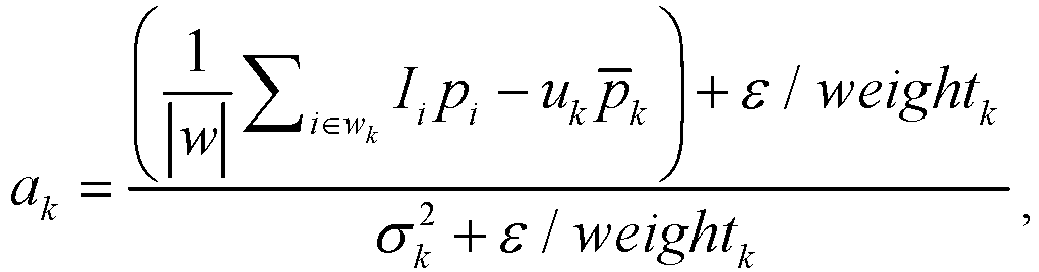
p k representing an average color value of all pixels in the third window,
- The
image enhancement unit 804 may determine the weight value of the first window according to the following formula:
- After determining the first linear relationship corresponding to each first window, the
image enhancement unit 804 may determine a second linear relationship corresponding to the first pixel according to the first linear relationship corresponding to each first window. The second linear relationship is used to describe a linear relationship between the first pixel and a pixel at a corresponding position in the third processed image. - Based on this, the
image enhancement unit 804 may determine a color value of each pixel in the third processed image according to a color value of each first pixel in the guidance image and the second linear relationship corresponding to each first pixel. In view of the above, the image enhancement apparatus 800 can obtain a third processed image with a high smoothness degree and an enhanced detail feature. Herein, according to the image enhancement apparatus 800, a noise reduction degree of an image is improved and a detail feature is enhanced, so that pictures are clearer, overall brightness is more uniform, a sense of layering is stronger, a contrast is higher, and colors are more vivid. If a contrast is higher, a color level of an image is higher, and a picture is fuller. In particular, the image enhancement apparatus 800 can achieve adaptive processing of image content, thereby improving robustness of image processing. In addition, in the image enhancement apparatus 800, brightness of the third processed image can be more uniform in the guidance image filtering manner. -
FIG. 9 is a schematic diagram of an image enhancement apparatus 900 according to some embodiments of this disclosure. A data processing device such as aterminal device 110 or avideo service system 150 may include the image enhancement apparatus 900. - As shown in
FIG. 9 , the image enhancement apparatus 900 may include afirst smoothing unit 901, adetail obtaining unit 902, an image superimposing unit 903, and animage enhancement unit 904. Herein, implementations of thefirst smoothing unit 901, thedetail obtaining unit 902, the image superimposing unit 903, and theimage enhancement unit 904 are consistent with the implementations of thefirst smoothing unit 801, thedetail obtaining unit 802, theimage superimposing unit 803, and theimage enhancement unit 804, and details are not described herein again. - In addition, the image enhancement apparatus 900 may further include a
second smoothing unit 905 configured to perform edge-preserving filtering on the third processed image to obtain a fourth processed image. In some embodiments, thesecond smoothing unit 905 processes the third processed image in a guidance image filtering manner by using the third processed image as a guidance image to obtain the fourth processed image. In this way, edge-preserving filtering is performed by using the third processed image as a guidance image, so that the image enhancement apparatus 900 can further improve a noise reduction degree, thereby enhancing an image enhancement effect. -
FIG. 10 shows a structural composition diagram of a data processing device. The data processing device may be implemented as aterminal device 110 or avideo service system 150. As shown inFIG. 10 , the data processing device includes one or more processors (CPU) 1002, acommunications module 1004, amemory 1006, a user interface 1010, and acommunications bus 1008 for interconnecting these components. - The
processor 1002 may receive and send data by using thecommunications module 1004 to implement network communication and/or local communication. - The user interface 1010 includes one or
more output devices 1012, including one or more speakers and/or one or more visualization displays. The user interface 1010 further includes one ormore input devices 1014. The user interface 1010 may, for example, receive an instruction of a remote control, but is not limited thereto. - The
memory 1006 may be a high-speed random access memory such as a DRAM, an SRAM, a DDR RAM, or other random access solid-state memory devices; or a non-volatile memory such as one or more magnetic disk storage devices, optical disc storage devices, flash memory devices, or other non-volatile solid-state memory devices. - The
memory 1006 stores a set of instructions executable by theprocessor 1002, including: - an
operating system 1016 including programs for handling various basic system services and executing a hardware-related task; and - an
application 1018 including various programs for implementing the above-mentioned image enhancement method, the programs implementing the processing procedure in the foregoing embodiment, for example, including the image enhancement apparatus 800 shown inFIG. 8 or the image enhancement apparatus 900 shown inFIG. 9 . In this way, the image enhancement apparatus can obtain a third processed image with a high smoothness degree and an enhanced detail feature. Herein, according to the image enhancement apparatus, a noise reduction degree of an image is improved and a detail feature is enhanced, so that pictures are clearer, overall brightness is more uniform, a sense of layering is stronger, a contrast is higher, and colors are more vivid. - In addition, each embodiment of this disclosure may be implemented by a data processing program executed by a data processing device such as a computer. Apparently, the data processing program constitutes this disclosure.
- In addition, generally, a data processing program stored in a storage medium is directly read from the storage medium for execution or the program is installed on or replicated to a storage device (such as a hard disk or memory) of a data processing device for execution. Therefore, such a storage medium also constitutes the present invention. The storage medium may use any type of recording manner, for example, a paper storage medium (such as paper tape), a magnetic storage medium (such as a floppy disk, a hard disk, and a flash memory), an optical storage medium (such as CD-ROM), and a magneto-optical storage medium (such as MO).
- Therefore, this disclosure further provides a non-volatile storage medium, which stores a data processing program. The data processing program is used for executing any one or part of the embodiments of the foregoing image enhancement method of this disclosure.
- In addition, the steps of the method of this disclosure may be implemented not only by the data processing program, but also by hardware, such as a logic gate, a switch, an Application Specific Integrated Circuit (ASIC), a programmable logic controller, and an embedded microcontroller. Therefore, the hardware that may implement the image enhancement method of this disclosure may also constitute this disclosure.
- The foregoing descriptions are merely exemplary embodiments of this disclosure, but are not intended to limit this disclosure. Any modification, equivalent replacement, or improvement made without departing from the spirit and principle of this disclosure falls within the protection scope of this disclosure.
Claims (20)
- An image enhancement method, performed by a data processing device, the method comprising:performing edge-preserving filtering on an original image to obtain a first processed image;obtaining a detail feature of the original image;determining a second processed image according to the detail feature and the first processed image; andprocessing the second processed image in a guidance image filtering manner by using the original image as a guidance image to obtain a third processed image.
- The method according to claim 1, the method further comprising:
performing edge-preserving filtering on the third processed image to obtain a fourth processed image. - The method according to claim 2, the performing edge-preserving filtering on the third processed image to obtain the fourth processed image comprising:
processing the third processed image in the guidance image filtering manner by using the third processed image as a guidance image to obtain the fourth processed image. - The method according to claim 1, the performing edge-preserving filtering on the original image to obtain the first processed image comprising:
processing the original image in the guidance image filtering manner by using the original image as a guidance image to obtain the first processed image. - The method according to claim 1, the obtaining the detail feature of the original image comprising:
determining a color difference between the original image and the first processed image, and determining the detail feature according to the color difference. - The method according to claim 5, the determining the color difference between the original image and the first processed image comprising:
determining a difference between the original image and the first processed image on one or more color channels, and determining the difference as the color difference. - The method according to claim 6, wherein the original image is a grayscale image, and the determining the difference between the original image and the first processed image on one or more color channels, and determining the difference as the color difference comprising:
determining a grayscale value difference between the original image and the first processed image, and determining the grayscale value difference as the color difference. - The method according to claim 5, the determining the detail feature according to the color difference comprising:
enhancing the color difference according to an adjustment coefficient to obtain an enhanced color difference, and determining the enhanced color difference as the detail feature. - The method according to claim 5, the determining the detail feature according to the color difference comprising:
determining the color difference as the detail feature. - The method according to claim 1, the processing the second processed image in the guidance image filtering manner by using the original image as the guidance image to obtain a third processed image comprising:determining, for each first pixel in the guidance image, a first linear relationship between each first window comprising the first pixel and a second window at a corresponding position in the third processed image, both a size of each first window and a size of the second window at the corresponding position being a first size;determining a second linear relationship corresponding to the first pixel according to the first linear relationship corresponding to each first window, the second linear relationship describing a linear relationship between the first pixel and a pixel at the corresponding position in the third processed image; anddetermining a color value of each pixel in the third processed image according to a color value of each first pixel in the guidance image and the second linear relationship corresponding to each first pixel.
- The method according to claim 10, the determining the first linear relationship between each first window comprising the first pixel and the second window at a corresponding position in the third processed image comprising:determining a variance corresponding to the first window for any first window comprising the first pixel;determining a covariance between the first window and a third window at a corresponding position in the second processed image;determining a sum of the variance and a regularization coefficient threshold; anddetermining a ratio of the covariance to the sum as a slope of the first linear relationship corresponding to the first window.
- The method according to claim 10, the determining the first linear relationship between each first window comprising the first pixel and the second window at a corresponding position in the third processed image comprising:determining a variance corresponding to the first window;determining a covariance between the first window and the second window at a corresponding position in the second processed image;determining a weight value of a detail feature of the first window in the first processed image;determining a first ratio of a regularization coefficient threshold to the weight value; andbased on a sum of the covariance and the first ratio as a first value, and a sum of the variance and the first ratio as a second value, determining a ratio of the first value to the second value as a slope of the first linear relationship corresponding to the first window.
- The method according to claim 12, the determining the weight value of the detail feature of the first window in the first processed image comprising:determining a first variance corresponding to each first pixel in the guidance image and a corresponding second variance, the first variance representing a variance of a window that uses the first pixel as a center and whose size satisfies a second size, and the second variance representing a variance of a window that uses the first pixel as a center and whose size satisfies the first size;determining a product of a first variance corresponding to a center point of the first window and a corresponding second variance, and determining the one-half power of the product as a third value;determining a product of the first variance corresponding to each first pixel in the guidance image and the corresponding second variance, and determining an average value of the one-half power of a product corresponding to each first pixel as a fourth value; anddetermining a ratio of the third value to the fourth value as the weight value.
- The method according to claim 10, the determining the first linear relationship between each first window comprising the first pixel and the second window at a corresponding position in the third processed image comprising:
determining a slope of the first linear relationship according to the following formula:
p k representing an average color value of all pixels in the third window,
- The method according to claim 10, the determining the first linear relationship between each first window comprising the first pixel and the second window at a corresponding position in the third processed image comprising:determining a slope of the first linear relationship according to the following formula:

p k representing an average color value of all pixels in the third window, determining the weight value weightk of the first window according to the following formula:
- An image enhancement apparatus, comprising:a first smoothing unit configured to perform edge-preserving filtering on an original image to obtain a first processed image;a detail obtaining unit configured to obtain a detail feature of the original image;an image superimposing unit configured to determine a second processed image according to the detail feature and the first processed image; andan image enhancement unit configured to process the second processed image in a guidance image filtering manner by using the original image as a guidance image to obtain a third processed image.
- A video service system, comprising the image enhancement apparatus according to claim 16.
- A terminal device, comprising the image enhancement apparatus according to claim 16.
- A data processing device, comprising:one or more processors;a memory; andone or more programs stored in the memory and configured to be executed by the one or more processors, the one or more programs comprising an instruction for performing the image enhancement method according to any one of claims 1 to 15.
- A storage medium storing one or more programs, the one or more programs comprising an instruction, the instruction, when executed by a data processing device, causing the data processing device to perform the image enhancement method according to any one of claims 1 to 15.
Applications Claiming Priority (2)
| Application Number | Priority Date | Filing Date | Title |
|---|---|---|---|
| CN201810149722.1A CN108335275B (en) | 2018-02-13 | 2018-02-13 | Image enhancement method and device, computing equipment and storage medium |
| PCT/CN2019/074067 WO2019157966A1 (en) | 2018-02-13 | 2019-01-31 | Image enhancement method, data processing device, and storage medium |
Publications (3)
| Publication Number | Publication Date |
|---|---|
| EP3754590A1 true EP3754590A1 (en) | 2020-12-23 |
| EP3754590A4 EP3754590A4 (en) | 2021-03-24 |
| EP3754590B1 EP3754590B1 (en) | 2022-04-20 |
Family
ID=62929638
Family Applications (1)
| Application Number | Title | Priority Date | Filing Date |
|---|---|---|---|
| EP19754702.9A Active EP3754590B1 (en) | 2018-02-13 | 2019-01-31 | Image enhancement method, data processing device, and storage medium |
Country Status (4)
| Country | Link |
|---|---|
| US (1) | US11263727B2 (en) |
| EP (1) | EP3754590B1 (en) |
| CN (1) | CN108335275B (en) |
| WO (1) | WO2019157966A1 (en) |
Families Citing this family (4)
| Publication number | Priority date | Publication date | Assignee | Title |
|---|---|---|---|---|
| CN108335275B (en) | 2018-02-13 | 2019-12-13 | 腾讯科技(深圳)有限公司 | Image enhancement method and device, computing equipment and storage medium |
| CN111899197B (en) * | 2020-08-05 | 2024-04-30 | 广州市百果园信息技术有限公司 | Image brightening and denoising method and device, mobile terminal and storage medium |
| CN115797238A (en) * | 2022-11-08 | 2023-03-14 | 北京极感科技有限公司 | image processing method |
| CN115937054A (en) * | 2022-12-12 | 2023-04-07 | 青岛海信日立空调系统有限公司 | An air conditioning system and its control method |
Family Cites Families (22)
| Publication number | Priority date | Publication date | Assignee | Title |
|---|---|---|---|---|
| CN102064796B (en) * | 2010-11-15 | 2014-09-17 | 中南大学 | Simplified weighted repeat pseudo-median filtering method with negative coefficients |
| WO2013038333A2 (en) * | 2011-09-18 | 2013-03-21 | Forus Health Pvt. Ltd. | Method and system for enhancing image quality |
| KR101401916B1 (en) | 2012-05-02 | 2014-06-10 | 민진식 | Upright rotation bicycle supporter |
| KR101341616B1 (en) * | 2012-05-10 | 2013-12-13 | 중앙대학교 산학협력단 | Apparatus and method for improving image by detail estimation |
| KR101736468B1 (en) * | 2012-12-24 | 2017-05-29 | 한화테크윈 주식회사 | Apparatus and method for processing image |
| JP6587317B2 (en) * | 2013-03-22 | 2019-10-09 | シナプティクス インコーポレイテッド | Guided filter-based detail enhancement |
| US9754356B2 (en) * | 2013-04-12 | 2017-09-05 | Agency For Science, Technology And Research | Method and system for processing an input image based on a guidance image and weights determined thereform |
| CN103337061B (en) * | 2013-07-18 | 2016-02-17 | 厦门大学 | A kind of based on repeatedly guiding the image of filtering to go sleet method |
| JP6287100B2 (en) * | 2013-11-20 | 2018-03-07 | 株式会社リコー | Image processing apparatus, image processing method, program, and storage medium |
| US9911179B2 (en) * | 2014-07-18 | 2018-03-06 | Dolby Laboratories Licensing Corporation | Image decontouring in high dynamic range video processing |
| US9779491B2 (en) * | 2014-08-15 | 2017-10-03 | Nikon Corporation | Algorithm and device for image processing |
| CN104318527A (en) * | 2014-10-21 | 2015-01-28 | 浙江工业大学 | Method for de-noising medical ultrasonic image based on wavelet transformation and guide filter |
| US20160241884A1 (en) * | 2015-02-13 | 2016-08-18 | Tandent Vision Science, Inc. | Selective perceptual masking via scale separation in the spatial and temporal domains for use in data compression with motion compensation |
| LU92673B1 (en) * | 2015-03-05 | 2016-09-06 | Iee Int Electronics & Eng Sa | Method and system for real-time noise removal and image enhancement of high-dynamic range images |
| JP6164238B2 (en) * | 2015-03-18 | 2017-07-19 | カシオ計算機株式会社 | Diagnostic device, image processing method in the diagnostic device, and program thereof |
| US20170109867A1 (en) * | 2015-10-16 | 2017-04-20 | Motorola Mobility Llc | Camera array for performing non-local means image processing over multiple sequential images |
| JP6635799B2 (en) * | 2016-01-20 | 2020-01-29 | キヤノン株式会社 | Image processing apparatus, image processing method, and program |
| US10223772B2 (en) * | 2016-03-22 | 2019-03-05 | Algolux Inc. | Method and system for denoising and demosaicing artifact suppression in digital images |
| US11113800B2 (en) * | 2017-01-18 | 2021-09-07 | Nvidia Corporation | Filtering image data using a neural network |
| CN107316279B (en) * | 2017-05-23 | 2019-11-22 | 天津大学 | Low-light Image Enhancement Method Based on Tone Mapping and Regularization Model |
| CN107481203B (en) * | 2017-08-14 | 2020-05-15 | 厦门美图之家科技有限公司 | Image-oriented filtering method and computing device |
| CN108335275B (en) * | 2018-02-13 | 2019-12-13 | 腾讯科技(深圳)有限公司 | Image enhancement method and device, computing equipment and storage medium |
-
2018
- 2018-02-13 CN CN201810149722.1A patent/CN108335275B/en active Active
-
2019
- 2019-01-31 WO PCT/CN2019/074067 patent/WO2019157966A1/en not_active Ceased
- 2019-01-31 EP EP19754702.9A patent/EP3754590B1/en active Active
-
2020
- 2020-06-16 US US16/902,481 patent/US11263727B2/en active Active
Also Published As
| Publication number | Publication date |
|---|---|
| CN108335275B (en) | 2019-12-13 |
| CN108335275A (en) | 2018-07-27 |
| US11263727B2 (en) | 2022-03-01 |
| WO2019157966A1 (en) | 2019-08-22 |
| EP3754590B1 (en) | 2022-04-20 |
| US20200311880A1 (en) | 2020-10-01 |
| EP3754590A4 (en) | 2021-03-24 |
Similar Documents
| Publication | Publication Date | Title |
|---|---|---|
| US12182979B2 (en) | Brightness and contrast enhancement for video | |
| US11263727B2 (en) | Image enhancement method, data processing device, and storage medium | |
| US10861133B1 (en) | Super-resolution video reconstruction method, device, apparatus and computer-readable storage medium | |
| US9652829B2 (en) | Video super-resolution by fast video segmentation for boundary accuracy control | |
| US12063335B2 (en) | Image processing method, image processing device, and computer device | |
| TW202032425A (en) | Method, apparatus and electronic device for image processing and storage medium | |
| US20200099823A1 (en) | System and method for image dynamic range adjusting | |
| US20180270489A1 (en) | Contrast optimization and local adaptation approach for high dynamic range compression | |
| CN109121000A (en) | A kind of method for processing video frequency and client | |
| US10043298B2 (en) | Enhanced document readability on devices | |
| US20110025701A1 (en) | Method and system for creating an image | |
| US20140198987A1 (en) | Structure Descriptors for Image Processing | |
| CN110097520B (en) | Image processing method and device | |
| CN113989404B (en) | Image processing method, device, equipment, storage medium and program product | |
| CN110858388B (en) | Method and device for enhancing video quality | |
| US11233970B2 (en) | Electronic apparatus and control method thereof | |
| US11348553B2 (en) | Color gamut mapping in the CIE 1931 color space | |
| US20150249843A1 (en) | Strong intra smoothing for in rext | |
| US10992873B2 (en) | Systems and methods for color matching for realistic flash images | |
| CN108470547B (en) | Backlight control method of display panel, computer readable medium and display device | |
| Hsia et al. | High‐performance high dynamic range image generation by inverted local patterns | |
| US10079981B2 (en) | Image dynamic range adjustment method, terminal, and storage medium | |
| US20170069063A1 (en) | Image processing apparatus and method, and decoding apparatus | |
| US20180047367A1 (en) | Adaptive color grade interpolation method and device | |
| EP3345084B1 (en) | Modification of graphical command tokens |
Legal Events
| Date | Code | Title | Description |
|---|---|---|---|
| STAA | Information on the status of an ep patent application or granted ep patent |
Free format text: STATUS: THE INTERNATIONAL PUBLICATION HAS BEEN MADE |
|
| PUAI | Public reference made under article 153(3) epc to a published international application that has entered the european phase |
Free format text: ORIGINAL CODE: 0009012 |
|
| STAA | Information on the status of an ep patent application or granted ep patent |
Free format text: STATUS: REQUEST FOR EXAMINATION WAS MADE |
|
| 17P | Request for examination filed |
Effective date: 20200812 |
|
| AK | Designated contracting states |
Kind code of ref document: A1 Designated state(s): AL AT BE BG CH CY CZ DE DK EE ES FI FR GB GR HR HU IE IS IT LI LT LU LV MC MK MT NL NO PL PT RO RS SE SI SK SM TR |
|
| AX | Request for extension of the european patent |
Extension state: BA ME |
|
| A4 | Supplementary search report drawn up and despatched |
Effective date: 20210223 |
|
| RIC1 | Information provided on ipc code assigned before grant |
Ipc: G06T 5/00 20060101AFI20210217BHEP |
|
| DAV | Request for validation of the european patent (deleted) | ||
| DAX | Request for extension of the european patent (deleted) | ||
| GRAP | Despatch of communication of intention to grant a patent |
Free format text: ORIGINAL CODE: EPIDOSNIGR1 |
|
| STAA | Information on the status of an ep patent application or granted ep patent |
Free format text: STATUS: GRANT OF PATENT IS INTENDED |
|
| INTG | Intention to grant announced |
Effective date: 20220126 |
|
| GRAS | Grant fee paid |
Free format text: ORIGINAL CODE: EPIDOSNIGR3 |
|
| GRAA | (expected) grant |
Free format text: ORIGINAL CODE: 0009210 |
|
| STAA | Information on the status of an ep patent application or granted ep patent |
Free format text: STATUS: THE PATENT HAS BEEN GRANTED |
|
| AK | Designated contracting states |
Kind code of ref document: B1 Designated state(s): AL AT BE BG CH CY CZ DE DK EE ES FI FR GB GR HR HU IE IS IT LI LT LU LV MC MK MT NL NO PL PT RO RS SE SI SK SM TR |
|
| REG | Reference to a national code |
Ref country code: GB Ref legal event code: FG4D |
|
| REG | Reference to a national code |
Ref country code: CH Ref legal event code: EP |
|
| REG | Reference to a national code |
Ref country code: DE Ref legal event code: R096 Ref document number: 602019013951 Country of ref document: DE |
|
| REG | Reference to a national code |
Ref country code: IE Ref legal event code: FG4D |
|
| REG | Reference to a national code |
Ref country code: AT Ref legal event code: REF Ref document number: 1485782 Country of ref document: AT Kind code of ref document: T Effective date: 20220515 |
|
| RAP4 | Party data changed (patent owner data changed or rights of a patent transferred) |
Owner name: TENCENT TECHNOLOGY (SHENZHEN) COMPANY LIMITED |
|
| REG | Reference to a national code |
Ref country code: LT Ref legal event code: MG9D |
|
| REG | Reference to a national code |
Ref country code: NL Ref legal event code: MP Effective date: 20220420 |
|
| REG | Reference to a national code |
Ref country code: AT Ref legal event code: MK05 Ref document number: 1485782 Country of ref document: AT Kind code of ref document: T Effective date: 20220420 |
|
| PG25 | Lapsed in a contracting state [announced via postgrant information from national office to epo] |
Ref country code: NL Free format text: LAPSE BECAUSE OF FAILURE TO SUBMIT A TRANSLATION OF THE DESCRIPTION OR TO PAY THE FEE WITHIN THE PRESCRIBED TIME-LIMIT Effective date: 20220420 |
|
| PG25 | Lapsed in a contracting state [announced via postgrant information from national office to epo] |
Ref country code: SE Free format text: LAPSE BECAUSE OF FAILURE TO SUBMIT A TRANSLATION OF THE DESCRIPTION OR TO PAY THE FEE WITHIN THE PRESCRIBED TIME-LIMIT Effective date: 20220420 Ref country code: PT Free format text: LAPSE BECAUSE OF FAILURE TO SUBMIT A TRANSLATION OF THE DESCRIPTION OR TO PAY THE FEE WITHIN THE PRESCRIBED TIME-LIMIT Effective date: 20220822 Ref country code: NO Free format text: LAPSE BECAUSE OF FAILURE TO SUBMIT A TRANSLATION OF THE DESCRIPTION OR TO PAY THE FEE WITHIN THE PRESCRIBED TIME-LIMIT Effective date: 20220720 Ref country code: LT Free format text: LAPSE BECAUSE OF FAILURE TO SUBMIT A TRANSLATION OF THE DESCRIPTION OR TO PAY THE FEE WITHIN THE PRESCRIBED TIME-LIMIT Effective date: 20220420 Ref country code: HR Free format text: LAPSE BECAUSE OF FAILURE TO SUBMIT A TRANSLATION OF THE DESCRIPTION OR TO PAY THE FEE WITHIN THE PRESCRIBED TIME-LIMIT Effective date: 20220420 Ref country code: GR Free format text: LAPSE BECAUSE OF FAILURE TO SUBMIT A TRANSLATION OF THE DESCRIPTION OR TO PAY THE FEE WITHIN THE PRESCRIBED TIME-LIMIT Effective date: 20220721 Ref country code: FI Free format text: LAPSE BECAUSE OF FAILURE TO SUBMIT A TRANSLATION OF THE DESCRIPTION OR TO PAY THE FEE WITHIN THE PRESCRIBED TIME-LIMIT Effective date: 20220420 Ref country code: ES Free format text: LAPSE BECAUSE OF FAILURE TO SUBMIT A TRANSLATION OF THE DESCRIPTION OR TO PAY THE FEE WITHIN THE PRESCRIBED TIME-LIMIT Effective date: 20220420 Ref country code: BG Free format text: LAPSE BECAUSE OF FAILURE TO SUBMIT A TRANSLATION OF THE DESCRIPTION OR TO PAY THE FEE WITHIN THE PRESCRIBED TIME-LIMIT Effective date: 20220720 Ref country code: AT Free format text: LAPSE BECAUSE OF FAILURE TO SUBMIT A TRANSLATION OF THE DESCRIPTION OR TO PAY THE FEE WITHIN THE PRESCRIBED TIME-LIMIT Effective date: 20220420 |
|
| PG25 | Lapsed in a contracting state [announced via postgrant information from national office to epo] |
Ref country code: RS Free format text: LAPSE BECAUSE OF FAILURE TO SUBMIT A TRANSLATION OF THE DESCRIPTION OR TO PAY THE FEE WITHIN THE PRESCRIBED TIME-LIMIT Effective date: 20220420 Ref country code: PL Free format text: LAPSE BECAUSE OF FAILURE TO SUBMIT A TRANSLATION OF THE DESCRIPTION OR TO PAY THE FEE WITHIN THE PRESCRIBED TIME-LIMIT Effective date: 20220420 Ref country code: LV Free format text: LAPSE BECAUSE OF FAILURE TO SUBMIT A TRANSLATION OF THE DESCRIPTION OR TO PAY THE FEE WITHIN THE PRESCRIBED TIME-LIMIT Effective date: 20220420 Ref country code: IS Free format text: LAPSE BECAUSE OF FAILURE TO SUBMIT A TRANSLATION OF THE DESCRIPTION OR TO PAY THE FEE WITHIN THE PRESCRIBED TIME-LIMIT Effective date: 20220820 |
|
| REG | Reference to a national code |
Ref country code: DE Ref legal event code: R097 Ref document number: 602019013951 Country of ref document: DE |
|
| PG25 | Lapsed in a contracting state [announced via postgrant information from national office to epo] |
Ref country code: SM Free format text: LAPSE BECAUSE OF FAILURE TO SUBMIT A TRANSLATION OF THE DESCRIPTION OR TO PAY THE FEE WITHIN THE PRESCRIBED TIME-LIMIT Effective date: 20220420 Ref country code: SK Free format text: LAPSE BECAUSE OF FAILURE TO SUBMIT A TRANSLATION OF THE DESCRIPTION OR TO PAY THE FEE WITHIN THE PRESCRIBED TIME-LIMIT Effective date: 20220420 Ref country code: RO Free format text: LAPSE BECAUSE OF FAILURE TO SUBMIT A TRANSLATION OF THE DESCRIPTION OR TO PAY THE FEE WITHIN THE PRESCRIBED TIME-LIMIT Effective date: 20220420 Ref country code: EE Free format text: LAPSE BECAUSE OF FAILURE TO SUBMIT A TRANSLATION OF THE DESCRIPTION OR TO PAY THE FEE WITHIN THE PRESCRIBED TIME-LIMIT Effective date: 20220420 Ref country code: DK Free format text: LAPSE BECAUSE OF FAILURE TO SUBMIT A TRANSLATION OF THE DESCRIPTION OR TO PAY THE FEE WITHIN THE PRESCRIBED TIME-LIMIT Effective date: 20220420 Ref country code: CZ Free format text: LAPSE BECAUSE OF FAILURE TO SUBMIT A TRANSLATION OF THE DESCRIPTION OR TO PAY THE FEE WITHIN THE PRESCRIBED TIME-LIMIT Effective date: 20220420 |
|
| PLBE | No opposition filed within time limit |
Free format text: ORIGINAL CODE: 0009261 |
|
| STAA | Information on the status of an ep patent application or granted ep patent |
Free format text: STATUS: NO OPPOSITION FILED WITHIN TIME LIMIT |
|
| 26N | No opposition filed |
Effective date: 20230123 |
|
| PG25 | Lapsed in a contracting state [announced via postgrant information from national office to epo] |
Ref country code: AL Free format text: LAPSE BECAUSE OF FAILURE TO SUBMIT A TRANSLATION OF THE DESCRIPTION OR TO PAY THE FEE WITHIN THE PRESCRIBED TIME-LIMIT Effective date: 20220420 |
|
| PG25 | Lapsed in a contracting state [announced via postgrant information from national office to epo] |
Ref country code: SI Free format text: LAPSE BECAUSE OF FAILURE TO SUBMIT A TRANSLATION OF THE DESCRIPTION OR TO PAY THE FEE WITHIN THE PRESCRIBED TIME-LIMIT Effective date: 20220420 |
|
| REG | Reference to a national code |
Ref country code: CH Ref legal event code: PL |
|
| PG25 | Lapsed in a contracting state [announced via postgrant information from national office to epo] |
Ref country code: LU Free format text: LAPSE BECAUSE OF NON-PAYMENT OF DUE FEES Effective date: 20230131 |
|
| REG | Reference to a national code |
Ref country code: BE Ref legal event code: MM Effective date: 20230131 |
|
| PG25 | Lapsed in a contracting state [announced via postgrant information from national office to epo] |
Ref country code: LI Free format text: LAPSE BECAUSE OF NON-PAYMENT OF DUE FEES Effective date: 20230131 Ref country code: CH Free format text: LAPSE BECAUSE OF NON-PAYMENT OF DUE FEES Effective date: 20230131 |
|
| PG25 | Lapsed in a contracting state [announced via postgrant information from national office to epo] |
Ref country code: BE Free format text: LAPSE BECAUSE OF NON-PAYMENT OF DUE FEES Effective date: 20230131 |
|
| PG25 | Lapsed in a contracting state [announced via postgrant information from national office to epo] |
Ref country code: IT Free format text: LAPSE BECAUSE OF FAILURE TO SUBMIT A TRANSLATION OF THE DESCRIPTION OR TO PAY THE FEE WITHIN THE PRESCRIBED TIME-LIMIT Effective date: 20220420 Ref country code: IE Free format text: LAPSE BECAUSE OF NON-PAYMENT OF DUE FEES Effective date: 20230131 |
|
| PG25 | Lapsed in a contracting state [announced via postgrant information from national office to epo] |
Ref country code: MC Free format text: LAPSE BECAUSE OF FAILURE TO SUBMIT A TRANSLATION OF THE DESCRIPTION OR TO PAY THE FEE WITHIN THE PRESCRIBED TIME-LIMIT Effective date: 20220420 |
|
| PG25 | Lapsed in a contracting state [announced via postgrant information from national office to epo] |
Ref country code: MC Free format text: LAPSE BECAUSE OF FAILURE TO SUBMIT A TRANSLATION OF THE DESCRIPTION OR TO PAY THE FEE WITHIN THE PRESCRIBED TIME-LIMIT Effective date: 20220420 |
|
| PG25 | Lapsed in a contracting state [announced via postgrant information from national office to epo] |
Ref country code: BG Free format text: LAPSE BECAUSE OF FAILURE TO SUBMIT A TRANSLATION OF THE DESCRIPTION OR TO PAY THE FEE WITHIN THE PRESCRIBED TIME-LIMIT Effective date: 20220420 |
|
| PG25 | Lapsed in a contracting state [announced via postgrant information from national office to epo] |
Ref country code: BG Free format text: LAPSE BECAUSE OF FAILURE TO SUBMIT A TRANSLATION OF THE DESCRIPTION OR TO PAY THE FEE WITHIN THE PRESCRIBED TIME-LIMIT Effective date: 20220420 |
|
| PG25 | Lapsed in a contracting state [announced via postgrant information from national office to epo] |
Ref country code: CY Free format text: LAPSE BECAUSE OF FAILURE TO SUBMIT A TRANSLATION OF THE DESCRIPTION OR TO PAY THE FEE WITHIN THE PRESCRIBED TIME-LIMIT; INVALID AB INITIO Effective date: 20190131 |
|
| PG25 | Lapsed in a contracting state [announced via postgrant information from national office to epo] |
Ref country code: HU Free format text: LAPSE BECAUSE OF FAILURE TO SUBMIT A TRANSLATION OF THE DESCRIPTION OR TO PAY THE FEE WITHIN THE PRESCRIBED TIME-LIMIT; INVALID AB INITIO Effective date: 20190131 |
|
| PG25 | Lapsed in a contracting state [announced via postgrant information from national office to epo] |
Ref country code: TR Free format text: LAPSE BECAUSE OF FAILURE TO SUBMIT A TRANSLATION OF THE DESCRIPTION OR TO PAY THE FEE WITHIN THE PRESCRIBED TIME-LIMIT Effective date: 20220420 |
|
| PGFP | Annual fee paid to national office [announced via postgrant information from national office to epo] |
Ref country code: GB Payment date: 20260122 Year of fee payment: 8 |
|
| PGFP | Annual fee paid to national office [announced via postgrant information from national office to epo] |
Ref country code: DE Payment date: 20260120 Year of fee payment: 8 |
|
| PGFP | Annual fee paid to national office [announced via postgrant information from national office to epo] |
Ref country code: FR Payment date: 20260121 Year of fee payment: 8 |