EP3754394A1 - Optical fiber - Google Patents
Optical fiber Download PDFInfo
- Publication number
- EP3754394A1 EP3754394A1 EP20180220.4A EP20180220A EP3754394A1 EP 3754394 A1 EP3754394 A1 EP 3754394A1 EP 20180220 A EP20180220 A EP 20180220A EP 3754394 A1 EP3754394 A1 EP 3754394A1
- Authority
- EP
- European Patent Office
- Prior art keywords
- cladding layer
- optical fiber
- core
- refractive index
- index difference
- Prior art date
- Legal status (The legal status is an assumption and is not a legal conclusion. Google has not performed a legal analysis and makes no representation as to the accuracy of the status listed.)
- Granted
Links
Images




Classifications
-
- G—PHYSICS
- G02—OPTICS
- G02B—OPTICAL ELEMENTS, SYSTEMS OR APPARATUS
- G02B6/00—Light guides; Structural details of arrangements comprising light guides and other optical elements, e.g. couplings
- G02B6/02—Optical fibres with cladding with or without a coating
- G02B6/028—Optical fibres with cladding with or without a coating with core or cladding having graded refractive index
- G02B6/0288—Multimode fibre, e.g. graded index core for compensating modal dispersion
-
- G—PHYSICS
- G02—OPTICS
- G02B—OPTICAL ELEMENTS, SYSTEMS OR APPARATUS
- G02B6/00—Light guides; Structural details of arrangements comprising light guides and other optical elements, e.g. couplings
- G02B6/02—Optical fibres with cladding with or without a coating
- G02B6/036—Optical fibres with cladding with or without a coating core or cladding comprising multiple layers
- G02B6/03616—Optical fibres characterised both by the number of different refractive index layers around the central core segment, i.e. around the innermost high index core layer, and their relative refractive index difference
- G02B6/03622—Optical fibres characterised both by the number of different refractive index layers around the central core segment, i.e. around the innermost high index core layer, and their relative refractive index difference having 2 layers only
- G02B6/03627—Optical fibres characterised both by the number of different refractive index layers around the central core segment, i.e. around the innermost high index core layer, and their relative refractive index difference having 2 layers only arranged - +
-
- C—CHEMISTRY; METALLURGY
- C03—GLASS; MINERAL OR SLAG WOOL
- C03B—MANUFACTURE, SHAPING, OR SUPPLEMENTARY PROCESSES
- C03B37/00—Manufacture or treatment of flakes, fibres, or filaments from softened glass, minerals, or slags
- C03B37/01—Manufacture of glass fibres or filaments
- C03B37/02—Manufacture of glass fibres or filaments by drawing or extruding, e.g. direct drawing of molten glass from nozzles; Cooling fins therefor
- C03B37/025—Manufacture of glass fibres or filaments by drawing or extruding, e.g. direct drawing of molten glass from nozzles; Cooling fins therefor from reheated softened tubes, rods, fibres or filaments, e.g. drawing fibres from preforms
- C03B37/027—Fibres composed of different sorts of glass, e.g. glass optical fibres
-
- C—CHEMISTRY; METALLURGY
- C03—GLASS; MINERAL OR SLAG WOOL
- C03C—CHEMICAL COMPOSITION OF GLASSES, GLAZES OR VITREOUS ENAMELS; SURFACE TREATMENT OF GLASS; SURFACE TREATMENT OF FIBRES OR FILAMENTS MADE FROM GLASS, MINERALS OR SLAGS; JOINING GLASS TO GLASS OR OTHER MATERIALS
- C03C3/00—Glass compositions
- C03C3/04—Glass compositions containing silica
-
- G—PHYSICS
- G02—OPTICS
- G02B—OPTICAL ELEMENTS, SYSTEMS OR APPARATUS
- G02B6/00—Light guides; Structural details of arrangements comprising light guides and other optical elements, e.g. couplings
- G02B6/02—Optical fibres with cladding with or without a coating
- G02B6/02004—Optical fibres with cladding with or without a coating characterised by the core effective area or mode field radius
- G02B6/02009—Large effective area or mode field radius, e.g. to reduce nonlinear effects in single mode fibres
- G02B6/02014—Effective area greater than 60 square microns in the C band, i.e. 1530-1565 nm
- G02B6/02019—Effective area greater than 90 square microns in the C band, i.e. 1530-1565 nm
-
- G—PHYSICS
- G02—OPTICS
- G02B—OPTICAL ELEMENTS, SYSTEMS OR APPARATUS
- G02B6/00—Light guides; Structural details of arrangements comprising light guides and other optical elements, e.g. couplings
- G02B6/02—Optical fibres with cladding with or without a coating
- G02B6/028—Optical fibres with cladding with or without a coating with core or cladding having graded refractive index
- G02B6/0283—Graded index region external to the central core segment, e.g. sloping layer or triangular or trapezoidal layer
-
- G—PHYSICS
- G02—OPTICS
- G02B—OPTICAL ELEMENTS, SYSTEMS OR APPARATUS
- G02B6/00—Light guides; Structural details of arrangements comprising light guides and other optical elements, e.g. couplings
- G02B6/02—Optical fibres with cladding with or without a coating
- G02B6/036—Optical fibres with cladding with or without a coating core or cladding comprising multiple layers
- G02B6/03694—Multiple layers differing in properties other than the refractive index, e.g. attenuation, diffusion, stress properties
-
- C—CHEMISTRY; METALLURGY
- C03—GLASS; MINERAL OR SLAG WOOL
- C03B—MANUFACTURE, SHAPING, OR SUPPLEMENTARY PROCESSES
- C03B2201/00—Type of glass produced
- C03B2201/06—Doped silica-based glasses
- C03B2201/08—Doped silica-based glasses doped with boron or fluorine or other refractive index decreasing dopant
- C03B2201/12—Doped silica-based glasses doped with boron or fluorine or other refractive index decreasing dopant doped with fluorine
-
- C—CHEMISTRY; METALLURGY
- C03—GLASS; MINERAL OR SLAG WOOL
- C03B—MANUFACTURE, SHAPING, OR SUPPLEMENTARY PROCESSES
- C03B2201/00—Type of glass produced
- C03B2201/06—Doped silica-based glasses
- C03B2201/30—Doped silica-based glasses doped with metals, e.g. Ga, Sn, Sb, Pb or Bi
- C03B2201/50—Doped silica-based glasses doped with metals, e.g. Ga, Sn, Sb, Pb or Bi doped with alkali metals
-
- C—CHEMISTRY; METALLURGY
- C03—GLASS; MINERAL OR SLAG WOOL
- C03B—MANUFACTURE, SHAPING, OR SUPPLEMENTARY PROCESSES
- C03B2201/00—Type of glass produced
- C03B2201/06—Doped silica-based glasses
- C03B2201/30—Doped silica-based glasses doped with metals, e.g. Ga, Sn, Sb, Pb or Bi
- C03B2201/54—Doped silica-based glasses doped with metals, e.g. Ga, Sn, Sb, Pb or Bi doped with beryllium, magnesium or alkaline earth metals
-
- C—CHEMISTRY; METALLURGY
- C03—GLASS; MINERAL OR SLAG WOOL
- C03B—MANUFACTURE, SHAPING, OR SUPPLEMENTARY PROCESSES
- C03B2203/00—Fibre product details, e.g. structure, shape
- C03B2203/10—Internal structure or shape details
- C03B2203/22—Radial profile of refractive index, composition or softening point
-
- C—CHEMISTRY; METALLURGY
- C03—GLASS; MINERAL OR SLAG WOOL
- C03B—MANUFACTURE, SHAPING, OR SUPPLEMENTARY PROCESSES
- C03B2203/00—Fibre product details, e.g. structure, shape
- C03B2203/10—Internal structure or shape details
- C03B2203/22—Radial profile of refractive index, composition or softening point
- C03B2203/23—Double or multiple optical cladding profiles
Definitions
- the present disclosure relates to an optical fiber.
- An optical fiber for transmitting signal light is desired to have a low transmission loss.
- a waveguide structure is formed by a core of which a refractive index is increased by adding germanium (Ge).
- Ge germanium
- F fluorine
- Patent Literature 1 discloses a method of reducing a transmission loss by reducing the viscosity difference (stress difference) between the core and the cladding adjacent to the core in the optical fiber in which the core does not contain Ge.
- the optical fiber described in Patent Literature 1 includes a core containing chlorine (Cl) without containing Ge and a cladding containing F. This optical fiber further includes a stress relaxation layer containing F between the core and the cladding.
- the optical fiber described in Patent Literature 2 includes a core and a cladding whose softening point difference is adjusted to 50°C or less so that the viscosities match.
- An optical fiber includes a core and a cladding which surrounds the core.
- the cladding includes an inner cladding layer which surrounds the core and an outer cladding layer which surrounds the inner cladding layer.
- a maximum value ⁇ n1max of a relative refractive index difference of the core, a minimum value ⁇ n2min of a relative refractive index difference of the inner cladding layer, and a maximum value ⁇ n3max of a relative refractive index difference of the outer cladding layer satisfy a relationship of ⁇ n2min ⁇ ⁇ n3max ⁇ ⁇ n1max.
- a residual stress ⁇ (r) at a radial position r satisfies
- An optical fiber includes a core and a cladding which surrounds the core.
- the cladding includes an inner cladding layer which surrounds the core and an outer cladding layer which surrounds the inner cladding layer.
- a maximum value ⁇ n1max of a relative refractive index difference of the core, a minimum value ⁇ n2min of a relative refractive index difference of the inner cladding layer, and a maximum value ⁇ n3max of a relative refractive index difference of the outer cladding layer respectively satisfy relationships of -0.15% ⁇ ⁇ n1max ⁇ 0.05%, - 0.5% ⁇ ⁇ n2min ⁇ -0.2%, and 0.02% ⁇ ⁇ n3max - ⁇ n2min ⁇ 0.2%.
- the core and the inner cladding layer contain an alkali metal element or an alkaline earth metal element.
- the outer cladding layer does not contain an alkali metal element and an alkaline earth metal element.
- An absolute value of a derivative of the relative refractive index difference with respect to a radial direction in the inner cladding layer and the outer cladding layer is 0.2%/ ⁇ m or less.
- a residual stress ⁇ (r) at a radial position r satisfies
- an optical fiber that reduces nonlinearity by increasing an effective area and an optical fiber that propagates multiple modes to a core have been proposed. These transmission optical fibers are also required to have low bending loss characteristics.
- an optical fiber having a refractive index distribution called a W-type or a trench-type in which a cladding is composed of two or more layers is generally used.
- the conventional method of reducing a transmission loss by viscous matching focuses on a difference in viscosity (stress) between the core and the cladding where optical power is concentrated, but the optical power actually has a wide distribution.
- a stress difference may be large in the cladding.
- a transmission loss increases due to structural irregularities. Therefore, in such an optical fiber, a sufficient transmission loss reduction effect cannot be obtained unless the viscosity (stress) difference in the cladding is taken into consideration.
- An object of the present disclosure is to provide an optical fiber having a low transmission loss while improving bending loss characteristics.
- An optical fiber includes a core and a cladding which surrounds the core.
- the cladding includes an inner cladding layer which surrounds the core and an outer cladding layer which surrounds the inner cladding layer.
- a maximum value ⁇ n1max of a relative refractive index difference of the core, a minimum value ⁇ n2min of a relative refractive index difference of the inner cladding layer, and a maximum value ⁇ n3max of a relative refractive index difference of the outer cladding layer satisfy a relationship of ⁇ n2min ⁇ ⁇ n3max ⁇ ⁇ n1max.
- a residual stress ⁇ (r) at a radial position r satisfies
- bending loss characteristics can be improved. Further, since a change in the residual stress is gentle as
- An effective area of a fundamental mode at a wavelength of 1550 nm may be 100 ⁇ m 2 or more. In this case, the communication capacity can be increased.
- a cable cutoff wavelength may be 1530 nm or less. In this case, it is possible to perform a single mode operation in the entire C band.
- a compressive stress may remain in the entire area of the core.
- a tensile stress remains in the core, a peripheral glass including the core is pulled.
- glass defects increase, and thus a transmission loss increases.
- the compressive stress remains in the entire area of the core, an increase in the transmission loss is suppressed.
- the core may contain an alkali metal element or an alkaline earth metal element.
- the viscosity of the core can be reduced when an optical fiber is manufactured by drawing an optical fiber preform. Accordingly, the relaxation of the glass structure is promoted and the transmission loss can be reduced.
- the transmission loss at the wavelength of 1550 nm may be 0.174 dB/km or less, 0.164 dB/km or less, or 0.154 dB/km or less.
- An optical fiber includes a core and a cladding which surrounds the core.
- the cladding includes an inner cladding layer which surrounds the core and an outer cladding layer which surrounds the inner cladding layer.
- a maximum value ⁇ n1max of a relative refractive index difference of the core, a minimum value ⁇ n2min of a relative refractive index difference of the inner cladding layer, and a maximum value ⁇ n3max of a relative refractive index difference of the outer cladding layer respectively satisfy relationships of -0.15% ⁇ ⁇ n1max ⁇ 0.05%, -0.5% ⁇ ⁇ n2min ⁇ -0.2%, and 0.02% ⁇ ⁇ n3max - ⁇ n2min ⁇ 0.2%.
- the core and the inner cladding layer contain an alkali metal element or an alkaline earth metal element.
- the outer cladding layer does not contain an alkali metal element and an alkaline earth metal element.
- An absolute value of a derivative of the relative refractive index difference with respect to a radial direction in the inner cladding layer and the outer cladding layer is 0.2%/ ⁇ m or less.
- a residual stress ⁇ (r) at a radial position r satisfies
- bending loss characteristics can be improved. Further, since a change in the residual stress is gentle as
- FIG. 1 is a cross-sectional view of an optical fiber according to an embodiment.
- an optical fiber 1 according to this embodiment includes a core 10, a cladding 20 surrounding the core 10, and a resin coating surrounding the cladding 20. The resin coating is not shown in Fig.1 .
- the cladding 20 has a multilayer structure having two or more layers.
- the cladding 20 includes an inner cladding layer 21 which surrounds the core 10 and an outer cladding layer 22 which surrounds the inner cladding layer 21.
- the cross-sectional view of FIG. 1 shows a cross-section perpendicular to the axial direction of the optical fiber 1.
- a core diameter (an outer diameter of the core 10) is, for example, 15 ⁇ m.
- An inner cladding layer diameter (an outer diameter of the inner cladding layer 21) is, for example, 50 ⁇ m.
- An outer cladding layer diameter (an outer diameter of the outer cladding layer 22) is, for example, 125 ⁇ m.
- the outer cladding layer diameter is also a cladding diameter (an outer diameter of the cladding 20).
- a compressive stress remains in the entire area of the core 10.
- the maximum value of the relative refractive index difference of the core 10 is ⁇ n1max
- the minimum value of the relative refractive index difference of the inner cladding layer 21 is ⁇ n2min
- the maximum value of the relative refractive index difference of the outer cladding layer 22 is ⁇ n3max
- a relationship of ⁇ n2min ⁇ ⁇ n3max ⁇ ⁇ n1max is satisfied and a W-type refractive index distribution is obtained.
- the relative refractive index difference is based on the refractive index of pure silica glass.
- the optical fiber 1 may have a "trench-type" refractive index distribution including a pedestal between the core 10 and the inner cladding layer 21.
- the pedestal has a relative refractive index difference substantially equal to the relative refractive index difference of the outer cladding layer 22.
- the optical fiber 1 may have a "vacancy imparting type" refractive index distribution in which the inner cladding layer 21 includes pores.
- the residual stress of the optical fiber can be measured using the phase change of light transmitted through the optical fiber.
- the residual stress indicates a stress component acting on a cross-section perpendicular to the axis of the optical fiber unless otherwise specified.
- the effective area (Aeff) (hereinafter, simply the "effective area") of the fundamental mode at the wavelength of 1550 nm is, for example, 100 ⁇ m 2 or more. Accordingly, the communication capacity can be increased.
- a cable cutoff wavelength is, for example, 1530 nm or less. For this reason, it is possible to perform a single mode operation in the entire C band.
- the transmission loss at the wavelength of 1550 nm may be 0.174 dB/km or less, 0.164 dB/km or less, or 0.154 dB/km or less.
- the core 10 contains an alkali metal element or an alkaline earth metal element. It can be said that the core 10 contains at least one or more elements from an element group consisting of an alkali metal element and an alkaline earth metal element.
- the core 10 contains, for example, potassium (K).
- the inner cladding layer 21 contains am alkali metal element or an alkaline earth metal element. It can be said that the inner cladding layer 21 contains at least one or more elements from an element group consisting of an alkali metal element and an alkaline earth metal element.
- the inner cladding layer 21 contains, for example, potassium (K).
- the outer cladding layer 22 does not contain an alkali metal element and an alkaline earth metal element.
- An absolute value of a derivative of the relative refractive index difference with respect to the radial direction in the inner cladding layer 21 and the outer cladding layer 22 is 0.2%/ ⁇ m or less. That is, when the relative refractive index difference of the optical fiber 1 is ⁇ n and the radial position is r, the inner cladding layer 21 and the outer cladding layer 22 have a relationship of
- of a derivative of the residual stress with respect to the radial direction is 30 MPa/ ⁇ m or less in the cladding 20. That is, a relationship of
- may be 20 MPa/ ⁇ m or less in the cladding 20. That is, a relationship of
- the optical fiber 1 is, for example, a single mode fiber (SMF).
- SMF single mode fiber
- the optical fiber 1 is not limited to the single mode fiber, and may be an optical fiber that propagates a plurality of modes as signal light. In higher-order modes, the effective cross-sectional area is large. Thus, in the transmission loss of the higher-order mode, the influence of the transmission loss due to the residual stress distribution of the cladding 20 tends to increase. As a result, the mode-dependent loss tends to increase. However, according to the optical fiber 1, mode-dependent loss can be reduced.
- the core 10 may have a ring core shape having a refractive index depression provided in the center and a ring surrounding the refractive index depression.
- the effective area can be increased while maintaining a mode field diameter (MFD). That is, it is possible to reduce nonlinearity while suppressing an increase in connection loss with a general-purpose single mode fiber.
- the cladding 20 may have three or more cladding layers as in the case of a trench-type refractive index profile.
- FIG. 2 is a diagram showing a refractive index distribution of an optical fiber according to a first example.
- a horizontal axis indicates a radial position r and a vertical axis indicates a relative refractive index difference based on a refractive index of pure silica glass.
- reference numerals "10", “20”, “21”, and “22” are given to the positions corresponding to the core, the cladding, the inner cladding layer, and the outer cladding layer.
- the optical fiber of the first example has a W-type refractive index distribution.
- the effective area is 150 ⁇ m 2 and the cable cutoff wavelength is 1420 nm or less.
- the core contains 100 ppm of potassium by mass.
- the core diameter is 15 ⁇ m and the inner cladding layer diameter is 50 ⁇ m.
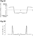
- FIG. 3A is a diagram showing a residual stress distribution of the optical fiber according to the first example.
- a horizontal axis indicates a radial position (r) and a vertical axis indicates a residual stress ( ⁇ ).
- FIG. 3B is a diagram showing a distribution of an absolute value of a derivative of the residual stress of the optical fiber according to the first example with respect to the radial direction.
- the horizontal axis indicates a radial position (r) and a vertical axis indicates an absolute value (
- minus corresponds to a compressive stress and plus corresponds to a tensile stress.
- a compressive stress remains in the entire area of the core.
- a compressive stress remains in the inner cladding layer and a tensile stress remains in the outer cladding layer.
- is 42 MPa/ ⁇ m.
- a refractive index difference is provided between the inner cladding layer and the outer cladding layer by adjusting the fluorine concentration.
- a viscosity difference also occurs between the inner cladding layer and the outer cladding layer.
- the residual stress sharply changes (in an interface) between the inner cladding layer and the outer cladding layer.
- a sharp change in the residual stress increases the transmission loss due to glass defects or structural irregularities.
- the transmission loss of the optical fiber of the first example is 0.156 dB/km.
- FIG. 4 is a diagram showing a refractive index distribution of an optical fiber according to a second example.
- a horizontal axis indicates a radial position r and a vertical axis indicates a relative refractive index difference based on a refractive index of pure silica glass.
- reference numerals "10", “20”, “21”, and “22” are given to the positions corresponding to the core, the cladding, the inner cladding layer, and the outer cladding layer.
- the optical fiber of the second example was manufactured from a preform whose fluorine concentration distribution was adjusted so that the residual stress gradually changed between the inner cladding layer and the outer cladding layer.
- the optical fiber of the second example has a W-type refractive index distribution.
- the effective area is 150 ⁇ m 2 and the cable cutoff wavelength is 1420 nm or less.
- the core contains 100 ppm of potassium by mass.
- the core diameter is 15 ⁇ m and the inner cladding layer diameter is 50 ⁇ m.
- FIG. 5A is a diagram showing a residual stress distribution of the optical fiber according to the second example.
- a horizontal axis indicates a radial position (r) and a vertical axis indicates a residual stress ( ⁇ ).
- minus corresponds to a compressive stress and plus corresponds to a tensile stress.
- FIG. 5B is a diagram showing a distribution of an absolute value of a derivative of the residual stress of the optical fiber according to the second example with respect to the radial direction.
- a horizontal axis indicates a radial position (r) and a vertical axis indicates an absolute value (
- a compressive stress remains in the entire area of the core.
- a compressive stress remains in a portion near the core of the inner cladding layer.
- a residual stress gently changes from a compressive stress to a tensile stress in a portion near the outer cladding layer of the inner cladding layer.
- a tensile stress remains in the outer cladding layer.
- is 24 MPa/ ⁇ m.
- the transmission loss of the optical fiber of the second example is 0.152 dB/km.
- FIG. 6 is a graph showing a relationship between a transmission loss and an absolute value of a maximum derivative of a residual stress.
- a horizontal axis indicates a maximum value of
- the transmission loss can be reduced by setting
- the transmission loss can be further reduced by setting
- the fluorine concentration in the cladding was adjusted, but the method of adjusting the residual stress is not limited thereto.
- concentration distribution of another halogen element such as chlorine or bromine, germanium, phosphorus (P), an alkali metal element, or an alkaline earth metal element may be adjusted.
- an element such as sodium (Na) or potassium having a high diffusion rate in glass can have a desired residual stress distribution by adjusting conditions such as a drawing tension or a drawing speed to control the diffusion.
- a case in which a core portion of an optical fiber preform (glass preform) contains potassium is considered.
- the diffusion speed of potassium is relatively fast. Accordingly, even if potassium is distributed in a center portion of the core portion in the optical fiber preform, potassium is diffused by heating during drawing particularly in a drawdown portion (a portion where the outer diameter decreases). As a result, potassium is distributed in the entire area in the fiber state.
- the residence time of potassium in the drawdown portion where diffusion easily occurs is shortened by increasing the drawing speed. Accordingly, it is possible to suppress the diffusion of potassium. Further, it is possible to suppress the diffusion of potassium by increasing a tension during drawing. This is because the effect of heat diffusion becomes weak when the temperature required for drawing the optical fiber from the optical fiber preform becomes lower as the tension becomes higher.
- FIG. 7 is a diagram showing a refractive index distribution and a potassium distribution of optical fibers according to a third example and a fourth example.
- a horizontal axis indicates a radial position r and a vertical axis indicates a relative refractive index difference based on a refractive index of pure silica glass.
- the vertical axis indicates a concentration (a.u.) of potassium.
- reference numerals "10", “20”, “21”, and “22” are given to the positions corresponding to the core, the cladding, the inner cladding layer, and the outer cladding layer.
- the refractive index distribution of the optical fibers of the third and fourth examples are indicated by a solid line, the potassium distribution of the optical fiber of the third example is indicated by a dashed line, and the potassium distribution of the optical fiber of the fourth example is indicated by a one-dotted chain line.
- the optical fibers of the third and fourth examples have a W-type refractive index distribution.
- the effective area is 150 ⁇ m 2 and the cable cutoff wavelength is 1420 nm or less.
- the core contains 100 ppm of potassium by mass.
- the core diameter is 15 ⁇ m and the inner cladding layer diameter is 50 ⁇ m.
- the optical fiber according to the third example was manufactured without adjusting the above-described drawing conditions (without adjustment of the drawing conditions).
- the optical fiber according to the fourth example was manufactured by adjusting the above-described drawing conditions (with adjustment of the drawing conditions).
- the optical fibers according to the third and fourth examples have the same refractive index distribution and have different potassium distributions. Potassium has an effect of reducing the viscosity of glass. For this reason, it is possible to adjust the residual stress distribution of the cladding by controlling the diffusion of potassium so that the potassium distribution range becomes appropriate. Specifically, the residual stress is not continuous in a boundary between an area with potassium and an area without potassium. Accordingly, a change (gradient) in the residual stress can be made gentle in the entire cladding.
- FIG. 8A is a diagram showing a residual stress distribution of the optical fiber according to the third example.
- a horizontal axis indicates a radial position (r) and a vertical axis indicates a residual stress ( ⁇ ).
- FIG. 8B is a diagram showing a distribution of an absolute value of a derivative of the residual stress of the optical fiber according to the third example with respect to the radial direction.
- a horizontal axis indicates a radial position (r) and a vertical axis indicates an absolute value (
- minus corresponds to a compressive stress and plus corresponds to a tensile stress.
- FIG. 9A is a diagram showing a residual stress distribution of the optical fiber according to the fourth example.
- a horizontal axis indicates a radial position (r) and a vertical axis indicates a residual stress ( ⁇ ).
- FIG. 9B is a diagram showing a distribution of an absolute value of a derivative of the residual stress of the optical fiber according to the fourth example with respect to the radial direction.
- a horizontal axis indicates a radial position (r) and a vertical axis indicates an absolute value (
- minus corresponds to a compressive stress and plus corresponds to a tensile stress.
- a compressive stress remains in the entire area of the core.
- a compressive stress remains also in a portion near the core of the inner cladding layer.
- a residual stress changes from a compressive stress to a tensile stress in a portion near the outer cladding layer of the inner cladding layer.
- a tensile stress remains in the outer cladding layer.
- a change in the residual stress in a portion near the outer cladding layer of the inner cladding layer is gentler than in the optical fiber of the third example.
- is 45 MPa/ ⁇ m, but in the optical fiber of the fourth example, the maximum value of
- the transmission loss of the optical fiber of the third example is 0.161 dB/km, but the transmission loss of the optical fiber of the fourth example is 0.154 dB/km.
Landscapes
- Physics & Mathematics (AREA)
- General Physics & Mathematics (AREA)
- Optics & Photonics (AREA)
- Chemical & Material Sciences (AREA)
- Engineering & Computer Science (AREA)
- Geochemistry & Mineralogy (AREA)
- Life Sciences & Earth Sciences (AREA)
- Materials Engineering (AREA)
- Organic Chemistry (AREA)
- Chemical Kinetics & Catalysis (AREA)
- General Chemical & Material Sciences (AREA)
- Dispersion Chemistry (AREA)
- General Life Sciences & Earth Sciences (AREA)
- Manufacturing & Machinery (AREA)
- Glass Compositions (AREA)
- Optical Fibers, Optical Fiber Cores, And Optical Fiber Bundles (AREA)
Abstract
Description
- The present application is based upon and claims the benefit of the priority from Japanese patent application No.
P2019-112800, filed on June 18, 2019 - The present disclosure relates to an optical fiber.
- An optical fiber for transmitting signal light is desired to have a low transmission loss. In general-purpose optical fibers, a waveguide structure is formed by a core of which a refractive index is increased by adding germanium (Ge). However, in such a core, since scattering loss due to Ge occurs, it is difficult to sufficiently reduce a transmission loss. Here, in order to reduce the scattering loss of the core, there has been proposed a structure in which silica glass having substantially no additive is used as the core and the refractive index of the cladding is reduced by adding fluorine (F). Incidentally, even in such a structure, a sufficient transmission loss reduction effect may not be obtained. This is because a difference in viscosity between the silica glass core and the cladding containing F is large. As a result, since the stress at the time of drawing is concentrated on the core, glass defects occur.
-
US Patent Application Publication No. 2016/0170137 (Patent Literature 1) andUS Patent Application Publication No. 2017/0219770 (Patent Literature 2) disclose a method of reducing a transmission loss by reducing the viscosity difference (stress difference) between the core and the cladding adjacent to the core in the optical fiber in which the core does not contain Ge. The optical fiber described inPatent Literature 1 includes a core containing chlorine (Cl) without containing Ge and a cladding containing F. This optical fiber further includes a stress relaxation layer containing F between the core and the cladding. The optical fiber described in Patent Literature 2 includes a core and a cladding whose softening point difference is adjusted to 50°C or less so that the viscosities match. - An optical fiber according to an embodiment of the present disclosure includes a core and a cladding which surrounds the core. The cladding includes an inner cladding layer which surrounds the core and an outer cladding layer which surrounds the inner cladding layer. A maximum value Δn1max of a relative refractive index difference of the core, a minimum value Δn2min of a relative refractive index difference of the inner cladding layer, and a maximum value Δn3max of a relative refractive index difference of the outer cladding layer satisfy a relationship of Δn2min < Δn3max < Δn1max. A residual stress σ(r) at a radial position r satisfies |dσ(r)/dr| ≤ 30 MPa/µm in the cladding.
- An optical fiber according to another embodiment of the present disclosure includes a core and a cladding which surrounds the core. The cladding includes an inner cladding layer which surrounds the core and an outer cladding layer which surrounds the inner cladding layer. A maximum value Δn1max of a relative refractive index difference of the core, a minimum value Δn2min of a relative refractive index difference of the inner cladding layer, and a maximum value Δn3max of a relative refractive index difference of the outer cladding layer respectively satisfy relationships of -0.15% < Δn1max < 0.05%, - 0.5% < Δn2min < -0.2%, and 0.02% < Δn3max - Δn2min < 0.2%. The core and the inner cladding layer contain an alkali metal element or an alkaline earth metal element. The outer cladding layer does not contain an alkali metal element and an alkaline earth metal element. An absolute value of a derivative of the relative refractive index difference with respect to a radial direction in the inner cladding layer and the outer cladding layer is 0.2%/µm or less. A residual stress σ(r) at a radial position r satisfies |dσ(r)/dr| ≤ 30 MPa/µm in the cladding.
- The foregoing and other purposes, aspects and advantages will be better understood from the following detailed description of a preferred embodiment of the invention with reference to the drawings, in which:
-
FIG. 1 is a cross-sectional view of an optical fiber according to an embodiment; -
FIG. 2 is a diagram showing a refractive index distribution of an optical fiber according to a first example; -
FIG. 3A is a diagram showing a residual stress distribution of the optical fiber according to the first example; -
FIG. 3B is a diagram showing a distribution of an absolute value of a derivative of a residual stress of the optical fiber according to the first example with respect to a radial direction ; -
FIG. 4 is a diagram showing a refractive index distribution of an optical fiber according to a second example; -
FIG. 5A is a diagram showing a residual stress distribution of the optical fiber according to the second example; -
FIG. 5B is a diagram showing a distribution of an absolute value of a derivative of a residual stress of the optical fiber according to the second example with respect to a radial direction; -
FIG. 6 is a graph showing a relationship between a transmission loss and an absolute value of a maximum derivative of a residual stress; -
FIG. 7 is a diagram showing a refractive index distribution and a potassium distribution of optical fibers according to a third example and a fourth example; -
FIG. 8A is a diagram showing a residual stress distribution of the optical fiber according to the third example; -
FIG. 8B is a diagram showing a distribution of an absolute value of a derivative of a residual stress of the optical fiber according to the third example with respect to a radial direction; -
FIG. 9A is a diagram showing a residual stress distribution of the optical fiber according to the fourth example; and -
FIG. 9B is a diagram showing a distribution of an absolute value of a derivative of a residual stress of the optical fiber according to the fourth example with respect to a radial direction. - In order to increase the communication capacity, an optical fiber that reduces nonlinearity by increasing an effective area and an optical fiber that propagates multiple modes to a core have been proposed. These transmission optical fibers are also required to have low bending loss characteristics. In order to improve the bending loss characteristics, an optical fiber having a refractive index distribution called a W-type or a trench-type in which a cladding is composed of two or more layers is generally used.
- The conventional method of reducing a transmission loss by viscous matching focuses on a difference in viscosity (stress) between the core and the cladding where optical power is concentrated, but the optical power actually has a wide distribution. Particularly, in an optical fiber having a multilayer cladding, a stress difference may be large in the cladding. In this case, a transmission loss increases due to structural irregularities. Therefore, in such an optical fiber, a sufficient transmission loss reduction effect cannot be obtained unless the viscosity (stress) difference in the cladding is taken into consideration.
- An object of the present disclosure is to provide an optical fiber having a low transmission loss while improving bending loss characteristics.
- According to the present disclosure, it is possible to provide an optical fiber having a low transmission loss while improving bending loss characteristics.
- First, embodiments of the present disclosure will be listed and described. An optical fiber according to an embodiment includes a core and a cladding which surrounds the core. The cladding includes an inner cladding layer which surrounds the core and an outer cladding layer which surrounds the inner cladding layer. A maximum value Δn1max of a relative refractive index difference of the core, a minimum value Δn2min of a relative refractive index difference of the inner cladding layer, and a maximum value Δn3max of a relative refractive index difference of the outer cladding layer satisfy a relationship of Δn2min < Δn3max < Δn1max. A residual stress σ(r) at a radial position r satisfies |dσ(r)/dr| ≤ 30 MPa/µm in the cladding.
- In the optical fiber according to the above-described embodiment, bending loss characteristics can be improved. Further, since a change in the residual stress is gentle as |dσ(r)/dr| ≤ 30 MPa/µm in the cladding, an increase in a transmission loss due to glass defects or structural irregularities can be suppressed.
- When the residual stress is σ and the radial position is r, |dσ/dr| ≤ 20 MPa/µm may be satisfied in the cladding. In this case, it is possible to further suppress an increase in the transmission loss.
- An effective area of a fundamental mode at a wavelength of 1550 nm may be 100 µm2 or more. In this case, the communication capacity can be increased.
- A cable cutoff wavelength may be 1530 nm or less. In this case, it is possible to perform a single mode operation in the entire C band.
- A compressive stress may remain in the entire area of the core. When a tensile stress remains in the core, a peripheral glass including the core is pulled. As a result, glass defects increase, and thus a transmission loss increases. In this case, since the compressive stress remains in the entire area of the core, an increase in the transmission loss is suppressed.
- The core may contain an alkali metal element or an alkaline earth metal element. In this case, the viscosity of the core can be reduced when an optical fiber is manufactured by drawing an optical fiber preform. Accordingly, the relaxation of the glass structure is promoted and the transmission loss can be reduced.
- The transmission loss at the wavelength of 1550 nm may be 0.174 dB/km or less, 0.164 dB/km or less, or 0.154 dB/km or less.
- An optical fiber according to another embodiment includes a core and a cladding which surrounds the core. The cladding includes an inner cladding layer which surrounds the core and an outer cladding layer which surrounds the inner cladding layer. A maximum value Δn1max of a relative refractive index difference of the core, a minimum value Δn2min of a relative refractive index difference of the inner cladding layer, and a maximum value Δn3max of a relative refractive index difference of the outer cladding layer respectively satisfy relationships of -0.15% < Δn1max < 0.05%, -0.5% < Δn2min < -0.2%, and 0.02% < Δn3max - Δn2min < 0.2%. The core and the inner cladding layer contain an alkali metal element or an alkaline earth metal element. The outer cladding layer does not contain an alkali metal element and an alkaline earth metal element. An absolute value of a derivative of the relative refractive index difference with respect to a radial direction in the inner cladding layer and the outer cladding layer is 0.2%/µm or less. A residual stress σ(r) at a radial position r satisfies |dσ(r)/dr| ≤ 30 MPa/µm in the cladding.
- In the optical fiber according to another embodiment, bending loss characteristics can be improved. Further, since a change in the residual stress is gentle as |dσ(r)/dr| ≤ 30 MPa/µm in the cladding, an increase in a transmission loss due to glass defects or structural irregularities can be suppressed.
- Detailed examples of the optical fiber of the present disclosure will be described below with reference to the drawings. Additionally, the invention is not limited to these examples and is expressed by the claims. It is intended to include all modifications within the meaning and scope equivalent to the claims. In the description of the drawings, the same components will be denoted by the same reference numerals and redundant description will be omitted.
-
FIG. 1 is a cross-sectional view of an optical fiber according to an embodiment. As shown inFIG. 1 , anoptical fiber 1 according to this embodiment includes a core 10, acladding 20 surrounding thecore 10, and a resin coating surrounding thecladding 20. The resin coating is not shown inFig.1 . In theoptical fiber 1, thecladding 20 has a multilayer structure having two or more layers. In this embodiment, thecladding 20 includes aninner cladding layer 21 which surrounds thecore 10 and anouter cladding layer 22 which surrounds theinner cladding layer 21. The cross-sectional view ofFIG. 1 shows a cross-section perpendicular to the axial direction of theoptical fiber 1. - A core diameter (an outer diameter of the core 10) is, for example, 15 µm. An inner cladding layer diameter (an outer diameter of the inner cladding layer 21) is, for example, 50 µm. An outer cladding layer diameter (an outer diameter of the outer cladding layer 22) is, for example, 125 µm. In this embodiment, the outer cladding layer diameter is also a cladding diameter (an outer diameter of the cladding 20).
- A compressive stress remains in the entire area of the
core 10. In theoptical fiber 1, when the maximum value of the relative refractive index difference of thecore 10 is Δn1max, the minimum value of the relative refractive index difference of theinner cladding layer 21 is Δn2min, and the maximum value of the relative refractive index difference of theouter cladding layer 22 is Δn3max, a relationship of Δn2min < Δn3max < Δn1max is satisfied and a W-type refractive index distribution is obtained. The relative refractive index difference is based on the refractive index of pure silica glass. Further, the relationships of -0.15% < Δn1max < 0.05%, -0.5% < Δn2min < -0.2%, and 0.02% < Δn3max - Δn2min < 0.2% may be satisfied. Accordingly, bending loss characteristics can be improved. Theoptical fiber 1 may have a "trench-type" refractive index distribution including a pedestal between the core 10 and theinner cladding layer 21. The pedestal has a relative refractive index difference substantially equal to the relative refractive index difference of theouter cladding layer 22. Theoptical fiber 1 may have a "vacancy imparting type" refractive index distribution in which theinner cladding layer 21 includes pores. - As described in P. L. Chu and T. Whitbread, "Measurement of stresses in optical fiber and preform" Appl. Opt. 21, 4241, 1982, the residual stress of the optical fiber can be measured using the phase change of light transmitted through the optical fiber. This document is hereby specifically incorporated herein by reference. Here, the residual stress indicates a stress component acting on a cross-section perpendicular to the axis of the optical fiber unless otherwise specified.
- In the
optical fiber 1, the effective area (Aeff) (hereinafter, simply the "effective area") of the fundamental mode at the wavelength of 1550 nm is, for example, 100 µm2 or more. Accordingly, the communication capacity can be increased. A cable cutoff wavelength is, for example, 1530 nm or less. For this reason, it is possible to perform a single mode operation in the entire C band. The transmission loss at the wavelength of 1550 nm may be 0.174 dB/km or less, 0.164 dB/km or less, or 0.154 dB/km or less. - The core 10 contains an alkali metal element or an alkaline earth metal element. It can be said that the core 10 contains at least one or more elements from an element group consisting of an alkali metal element and an alkaline earth metal element. The core 10 contains, for example, potassium (K). The
inner cladding layer 21 contains am alkali metal element or an alkaline earth metal element. It can be said that theinner cladding layer 21 contains at least one or more elements from an element group consisting of an alkali metal element and an alkaline earth metal element. Theinner cladding layer 21 contains, for example, potassium (K). Theouter cladding layer 22 does not contain an alkali metal element and an alkaline earth metal element. - An absolute value of a derivative of the relative refractive index difference with respect to the radial direction in the
inner cladding layer 21 and theouter cladding layer 22 is 0.2%/µm or less. That is, when the relative refractive index difference of theoptical fiber 1 is Δn and the radial position is r, theinner cladding layer 21 and theouter cladding layer 22 have a relationship of |dΔn/dr| ≤ 0.2%/µm. Accordingly, since a viscosity difference hardly occurs between theinner cladding layer 21 and theouter cladding layer 22, a sharp change in the residual stress is suppressed. As a result, since glass defects or structural irregularities are suppressed, an increase in the transmission loss can be suppressed. - When the residual stress is σ and the radial position is r, an absolute value |dσ/dr| of a derivative of the residual stress with respect to the radial direction is 30 MPa/µm or less in the
cladding 20. That is, a relationship of |dσ/dr| ≤ 30 MPa/µm is satisfied in thecladding 20. In this way, since a change (gradient) in the residual stress in thecladding 20 becomes gentle, an increase in the transmission loss due to glass defects or structural irregularities can be suppressed. |dσ/dr| may be 20 MPa/µm or less in thecladding 20. That is, a relationship of |dσ/dr| ≤ 20 MPa/µm may be satisfied in thecladding 20. In this case, since a change (gradient) in the residual stress is gentler in thecladding 20, an increase in the transmission loss can be further suppressed. - The
optical fiber 1 is, for example, a single mode fiber (SMF). Theoptical fiber 1 is not limited to the single mode fiber, and may be an optical fiber that propagates a plurality of modes as signal light. In higher-order modes, the effective cross-sectional area is large. Thus, in the transmission loss of the higher-order mode, the influence of the transmission loss due to the residual stress distribution of thecladding 20 tends to increase. As a result, the mode-dependent loss tends to increase. However, according to theoptical fiber 1, mode-dependent loss can be reduced. - The core 10 may have a ring core shape having a refractive index depression provided in the center and a ring surrounding the refractive index depression. By adopting the ring core shape, the effective area can be increased while maintaining a mode field diameter (MFD). That is, it is possible to reduce nonlinearity while suppressing an increase in connection loss with a general-purpose single mode fiber. The
cladding 20 may have three or more cladding layers as in the case of a trench-type refractive index profile. - Hereinafter, examples will be described.
FIG. 2 is a diagram showing a refractive index distribution of an optical fiber according to a first example. InFIG. 2 , a horizontal axis indicates a radial position r and a vertical axis indicates a relative refractive index difference based on a refractive index of pure silica glass. For reference, inFIG. 2 , reference numerals "10", "20", "21", and "22" are given to the positions corresponding to the core, the cladding, the inner cladding layer, and the outer cladding layer. The optical fiber of the first example has a W-type refractive index distribution. In the optical fiber of the first example, the effective area is 150 µm2 and the cable cutoff wavelength is 1420 nm or less. The core contains 100 ppm of potassium by mass. The core diameter is 15 µm and the inner cladding layer diameter is 50 µm. -
FIG. 3A is a diagram showing a residual stress distribution of the optical fiber according to the first example. InFIG. 3A , a horizontal axis indicates a radial position (r) and a vertical axis indicates a residual stress (σ).FIG. 3B is a diagram showing a distribution of an absolute value of a derivative of the residual stress of the optical fiber according to the first example with respect to the radial direction. InFIG. 3B , the horizontal axis indicates a radial position (r) and a vertical axis indicates an absolute value (|dσ(r)/dr|) of a derivative of the residual stress with respect to the radial direction. InFIG. 3A , minus corresponds to a compressive stress and plus corresponds to a tensile stress. - As shown in
FIG. 3A , a compressive stress remains in the entire area of the core. A compressive stress remains in the inner cladding layer and a tensile stress remains in the outer cladding layer. As shown inFIG. 3B , a maximum value of |dσ(r)/dr| is 42 MPa/µm. - In the optical fiber of the first example, a refractive index difference is provided between the inner cladding layer and the outer cladding layer by adjusting the fluorine concentration. At the same time, a viscosity difference also occurs between the inner cladding layer and the outer cladding layer. Thus, the residual stress sharply changes (in an interface) between the inner cladding layer and the outer cladding layer. A sharp change in the residual stress increases the transmission loss due to glass defects or structural irregularities. The transmission loss of the optical fiber of the first example is 0.156 dB/km.
-
FIG. 4 is a diagram showing a refractive index distribution of an optical fiber according to a second example. InFIG. 4 , a horizontal axis indicates a radial position r and a vertical axis indicates a relative refractive index difference based on a refractive index of pure silica glass. For reference, inFIG. 4 , reference numerals "10", "20", "21", and "22" are given to the positions corresponding to the core, the cladding, the inner cladding layer, and the outer cladding layer. As shown inFIG. 4 , the optical fiber of the second example was manufactured from a preform whose fluorine concentration distribution was adjusted so that the residual stress gradually changed between the inner cladding layer and the outer cladding layer. The optical fiber of the second example has a W-type refractive index distribution. In the optical fiber of the second example, the effective area is 150 µm2 and the cable cutoff wavelength is 1420 nm or less. The core contains 100 ppm of potassium by mass. The core diameter is 15 µm and the inner cladding layer diameter is 50 µm. -
FIG. 5A is a diagram showing a residual stress distribution of the optical fiber according to the second example. InFIG. 5A , a horizontal axis indicates a radial position (r) and a vertical axis indicates a residual stress (σ). InFIG. 5A , minus corresponds to a compressive stress and plus corresponds to a tensile stress.FIG. 5B is a diagram showing a distribution of an absolute value of a derivative of the residual stress of the optical fiber according to the second example with respect to the radial direction. InFIG. 5B , a horizontal axis indicates a radial position (r) and a vertical axis indicates an absolute value (|dσ/dr|) of a derivative of the residual stress with respect to the radial direction. - As shown in
FIG. 5A , a compressive stress remains in the entire area of the core. A compressive stress remains in a portion near the core of the inner cladding layer. A residual stress gently changes from a compressive stress to a tensile stress in a portion near the outer cladding layer of the inner cladding layer. A tensile stress remains in the outer cladding layer. As shown inFIG. 5B , a maximum value of |dσ/dr| is 24 MPa/µm. The transmission loss of the optical fiber of the second example is 0.152 dB/km. -
FIG. 6 is a graph showing a relationship between a transmission loss and an absolute value of a maximum derivative of a residual stress. InFIG. 6 , a horizontal axis indicates a maximum value of |dσ/dr| of a cladding and a vertical axis indicates a transmission loss. As shown inFIG. 6 , the transmission loss can be reduced by setting |dσ/dr| to 30 MPa/µm or less. The transmission loss can be further reduced by setting |dσ/dr| to be 20 MPa/µm or less. - In the second example, as a method of adjusting a change in the residual stress to be gentle, the fluorine concentration in the cladding was adjusted, but the method of adjusting the residual stress is not limited thereto. The concentration distribution of another halogen element such as chlorine or bromine, germanium, phosphorus (P), an alkali metal element, or an alkaline earth metal element may be adjusted. Further, for example, an element such as sodium (Na) or potassium having a high diffusion rate in glass can have a desired residual stress distribution by adjusting conditions such as a drawing tension or a drawing speed to control the diffusion.
- A case in which a core portion of an optical fiber preform (glass preform) contains potassium is considered. The diffusion speed of potassium is relatively fast. Accordingly, even if potassium is distributed in a center portion of the core portion in the optical fiber preform, potassium is diffused by heating during drawing particularly in a drawdown portion (a portion where the outer diameter decreases). As a result, potassium is distributed in the entire area in the fiber state.
- For example, the residence time of potassium in the drawdown portion where diffusion easily occurs is shortened by increasing the drawing speed. Accordingly, it is possible to suppress the diffusion of potassium. Further, it is possible to suppress the diffusion of potassium by increasing a tension during drawing. This is because the effect of heat diffusion becomes weak when the temperature required for drawing the optical fiber from the optical fiber preform becomes lower as the tension becomes higher.
-
FIG. 7 is a diagram showing a refractive index distribution and a potassium distribution of optical fibers according to a third example and a fourth example. InFIG. 7 , a horizontal axis indicates a radial position r and a vertical axis indicates a relative refractive index difference based on a refractive index of pure silica glass. The vertical axis indicates a concentration (a.u.) of potassium. For reference, inFIG. 7 , reference numerals "10", "20", "21", and "22" are given to the positions corresponding to the core, the cladding, the inner cladding layer, and the outer cladding layer. The refractive index distribution of the optical fibers of the third and fourth examples are indicated by a solid line, the potassium distribution of the optical fiber of the third example is indicated by a dashed line, and the potassium distribution of the optical fiber of the fourth example is indicated by a one-dotted chain line. The optical fibers of the third and fourth examples have a W-type refractive index distribution. In the optical fibers of the third and fourth examples, the effective area is 150 µm2 and the cable cutoff wavelength is 1420 nm or less. The core contains 100 ppm of potassium by mass. The core diameter is 15 µm and the inner cladding layer diameter is 50 µm. - The optical fiber according to the third example was manufactured without adjusting the above-described drawing conditions (without adjustment of the drawing conditions). The optical fiber according to the fourth example was manufactured by adjusting the above-described drawing conditions (with adjustment of the drawing conditions). The optical fibers according to the third and fourth examples have the same refractive index distribution and have different potassium distributions. Potassium has an effect of reducing the viscosity of glass. For this reason, it is possible to adjust the residual stress distribution of the cladding by controlling the diffusion of potassium so that the potassium distribution range becomes appropriate. Specifically, the residual stress is not continuous in a boundary between an area with potassium and an area without potassium. Accordingly, a change (gradient) in the residual stress can be made gentle in the entire cladding.
-
FIG. 8A is a diagram showing a residual stress distribution of the optical fiber according to the third example. InFIG. 8A , a horizontal axis indicates a radial position (r) and a vertical axis indicates a residual stress (σ).FIG. 8B is a diagram showing a distribution of an absolute value of a derivative of the residual stress of the optical fiber according to the third example with respect to the radial direction. InFIG. 8B , a horizontal axis indicates a radial position (r) and a vertical axis indicates an absolute value (|dσ/dr|) of a derivative of the residual stress with respect to the radial direction. InFIG. 8A , minus corresponds to a compressive stress and plus corresponds to a tensile stress. -
FIG. 9A is a diagram showing a residual stress distribution of the optical fiber according to the fourth example. InFIG. 9A , a horizontal axis indicates a radial position (r) and a vertical axis indicates a residual stress (σ).FIG. 9B is a diagram showing a distribution of an absolute value of a derivative of the residual stress of the optical fiber according to the fourth example with respect to the radial direction. InFIG. 9B , a horizontal axis indicates a radial position (r) and a vertical axis indicates an absolute value (|dσ/dr|) of a derivative of the residual stress with respect to the radial direction. InFIG. 9A , minus corresponds to a compressive stress and plus corresponds to a tensile stress. - As shown in
FIGS. 8A and9A , in any one of the optical fibers of the third and fourth examples, a compressive stress remains in the entire area of the core. A compressive stress remains also in a portion near the core of the inner cladding layer. A residual stress changes from a compressive stress to a tensile stress in a portion near the outer cladding layer of the inner cladding layer. A tensile stress remains in the outer cladding layer. In the optical fiber of the fourth example, a change in the residual stress in a portion near the outer cladding layer of the inner cladding layer is gentler than in the optical fiber of the third example. - As shown in
FIGS. 8B and9B , in the optical fiber of the third example, the maximum value of |dσ/dr| is 45 MPa/µm, but in the optical fiber of the fourth example, the maximum value of |dσ/dr| is 28 MPa/µm. The transmission loss of the optical fiber of the third example is 0.161 dB/km, but the transmission loss of the optical fiber of the fourth example is 0.154 dB/km.
Claims (10)
- An optical fiber comprising:a core; anda cladding which surrounds the core,wherein the cladding includes an inner cladding layer which surrounds the core and an outer cladding layer which surrounds the inner cladding layer,wherein a maximum value Δn1max of a relative refractive index difference of the core, a minimum value Δn2min of a relative refractive index difference of the inner cladding layer, and a maximum value Δn3max of a relative refractive index difference of the outer cladding layer satisfy a relationship of Δn2min < Δn3max < Δn1max, andwherein a residual stress σ(r) at a radial position r satisfies |dσ(r)/dr| ≤ 30 MPa/µm in the cladding.
- The optical fiber according to claim 1,
wherein the residual stress σ(r) satisfies a formula, |dσ(r)/dr| ≤ 20 MPa/µm in the cladding. - The optical fiber according to claim 1 or 2,
wherein an effective area of a fundamental mode at a wavelength of 1550 nm is 100 µm2 or more. - The optical fiber according to claim 3,
wherein a cable cutoff wavelength is 1530 nm or less. - The optical fiber according to any one of claims 1 to 4,
wherein a compressive stress remains in an entire area of the core. - The optical fiber according to any one of claims 1 to 5,
wherein the core contains an alkali metal element or an alkaline earth metal element. - The optical fiber according to any one of claims 1 to 6,
wherein a transmission loss at a wavelength of 1550 nm is 0.174 dB/km or less. - The optical fiber according to any one of claims 1 to 6,
wherein a transmission loss at a wavelength of 1550 nm is 0.164 dB/km or less. - The optical fiber according to any one of claims 1 to 6,
wherein a transmission loss at a wavelength of 1550 nm is 0.154 dB/km or less. - An optical fiber comprising:a core; anda cladding which surrounds the core,wherein the cladding includes an inner cladding layer which surrounds the core and an outer cladding layer which surrounds the inner cladding layer,wherein a maximum value Δn1max of a relative refractive index difference of the core, a minimum value Δn2min of a relative refractive index difference of the inner cladding layer, and a maximum value Δn3max of a relative refractive index difference of the outer cladding layer respectively satisfy relationships of -0.15% < Δn1max < 0.05%, -0.5% < Δn2min < -0.2%, and 0.02% < Δn3max - Δn2min < 0.2%,wherein the core and the inner cladding layer contain an alkali metal element or an alkaline earth metal element,wherein the outer cladding layer does not contain an alkali metal element and an alkaline earth metal element,wherein an absolute value of a derivative of the relative refractive index difference with respect to a radial direction in the inner cladding layer and the outer cladding layer is 0.2%/µm or less, andwherein a residual stress σ(r) at a radial position r satisfies |dσ(r)/dr| ≤ 30 MPa/µm in the cladding.
Applications Claiming Priority (1)
| Application Number | Priority Date | Filing Date | Title |
|---|---|---|---|
| JP2019112800A JP7326906B2 (en) | 2019-06-18 | 2019-06-18 | optical fiber |
Publications (2)
| Publication Number | Publication Date |
|---|---|
| EP3754394A1 true EP3754394A1 (en) | 2020-12-23 |
| EP3754394B1 EP3754394B1 (en) | 2022-09-21 |
Family
ID=71103279
Family Applications (1)
| Application Number | Title | Priority Date | Filing Date |
|---|---|---|---|
| EP20180220.4A Active EP3754394B1 (en) | 2019-06-18 | 2020-06-16 | Optical fiber |
Country Status (5)
| Country | Link |
|---|---|
| US (1) | US20200400879A1 (en) |
| EP (1) | EP3754394B1 (en) |
| JP (1) | JP7326906B2 (en) |
| CN (1) | CN112099134B (en) |
| DK (1) | DK3754394T3 (en) |
Families Citing this family (3)
| Publication number | Priority date | Publication date | Assignee | Title |
|---|---|---|---|---|
| JP7717474B2 (en) * | 2021-03-11 | 2025-08-04 | 古河電気工業株式会社 | Multicore fiber, multicore fiber manufacturing method, multicore fiber preform, and multicore fiber preform manufacturing method |
| US20250052947A1 (en) * | 2021-12-24 | 2025-02-13 | Sumitomo Electric Industries, Ltd. | Bent optical fiber, method for manufacturing bent optical fiber, and optical connection component |
| WO2025143138A1 (en) * | 2023-12-28 | 2025-07-03 | 住友電気工業株式会社 | Optical fiber |
Citations (6)
| Publication number | Priority date | Publication date | Assignee | Title |
|---|---|---|---|---|
| JP2005343703A (en) * | 2004-05-31 | 2005-12-15 | Fujikura Ltd | Manufacturing method of optical fiber, optical fiber |
| JP2007297254A (en) * | 2006-05-02 | 2007-11-15 | Hitachi Cable Ltd | Optical fiber |
| US20130064513A1 (en) * | 2011-09-14 | 2013-03-14 | Sumitomo Electric Industries, Ltd. | Optical fiber |
| US20160170137A1 (en) | 2014-10-21 | 2016-06-16 | Ofs Fitel, Llc | Low Loss Optical Fiber And Method Of Making The Same |
| US20170219770A1 (en) | 2014-06-24 | 2017-08-03 | Corning Incorporated | Low attenuation fiber with viscosity matched core and inner clad |
| US20170371096A1 (en) * | 2016-02-26 | 2017-12-28 | Sumitomo Electric Industries, Ltd. | Optical fiber |
Family Cites Families (10)
| Publication number | Priority date | Publication date | Assignee | Title |
|---|---|---|---|---|
| US6515795B1 (en) * | 2001-06-29 | 2003-02-04 | Corning Incorporated | Borosilicate cladding glasses for germanate core thulium-doped amplifiers |
| JP2003207675A (en) | 2002-01-11 | 2003-07-25 | Sumitomo Electric Ind Ltd | Quartz optical fiber and method of manufacturing the same |
| JP4999063B2 (en) * | 2006-10-19 | 2012-08-15 | 古河電気工業株式会社 | Optical fiber |
| JP5949016B2 (en) | 2011-06-15 | 2016-07-06 | 住友電気工業株式会社 | Optical fiber manufacturing method |
| JP5799903B2 (en) | 2012-07-03 | 2015-10-28 | 日立金属株式会社 | Single mode optical fiber |
| JP6337509B2 (en) * | 2014-02-24 | 2018-06-06 | 住友電気工業株式会社 | Optical fiber preform manufacturing method |
| WO2016017743A1 (en) * | 2014-08-01 | 2016-02-04 | 株式会社フジクラ | Optical fiber and method for producing same |
| JP2016148749A (en) * | 2015-02-12 | 2016-08-18 | 株式会社フジクラ | Dispersion shifted optical fiber |
| CN107162401B (en) * | 2017-05-31 | 2019-11-26 | 长飞光纤光缆股份有限公司 | A method of preparing ultralow attenuating fiber |
| CN107102400B (en) * | 2017-06-28 | 2020-01-14 | 长飞光纤光缆股份有限公司 | High-bandwidth bending insensitive multimode optical fiber |
-
2019
- 2019-06-18 JP JP2019112800A patent/JP7326906B2/en active Active
-
2020
- 2020-06-11 US US16/899,006 patent/US20200400879A1/en not_active Abandoned
- 2020-06-16 DK DK20180220.4T patent/DK3754394T3/en active
- 2020-06-16 CN CN202010546314.7A patent/CN112099134B/en active Active
- 2020-06-16 EP EP20180220.4A patent/EP3754394B1/en active Active
Patent Citations (6)
| Publication number | Priority date | Publication date | Assignee | Title |
|---|---|---|---|---|
| JP2005343703A (en) * | 2004-05-31 | 2005-12-15 | Fujikura Ltd | Manufacturing method of optical fiber, optical fiber |
| JP2007297254A (en) * | 2006-05-02 | 2007-11-15 | Hitachi Cable Ltd | Optical fiber |
| US20130064513A1 (en) * | 2011-09-14 | 2013-03-14 | Sumitomo Electric Industries, Ltd. | Optical fiber |
| US20170219770A1 (en) | 2014-06-24 | 2017-08-03 | Corning Incorporated | Low attenuation fiber with viscosity matched core and inner clad |
| US20160170137A1 (en) | 2014-10-21 | 2016-06-16 | Ofs Fitel, Llc | Low Loss Optical Fiber And Method Of Making The Same |
| US20170371096A1 (en) * | 2016-02-26 | 2017-12-28 | Sumitomo Electric Industries, Ltd. | Optical fiber |
Non-Patent Citations (1)
| Title |
|---|
| P. L. CHUT. WHITBREAD: "Measurement of stresses in optical fiber and preform", APPL. OPT., vol. 21, 1982, pages 4241 |
Also Published As
| Publication number | Publication date |
|---|---|
| JP2020204727A (en) | 2020-12-24 |
| EP3754394B1 (en) | 2022-09-21 |
| CN112099134A (en) | 2020-12-18 |
| CN112099134B (en) | 2025-02-11 |
| DK3754394T3 (en) | 2022-11-07 |
| US20200400879A1 (en) | 2020-12-24 |
| JP7326906B2 (en) | 2023-08-16 |
Similar Documents
| Publication | Publication Date | Title |
|---|---|---|
| EP2107402B1 (en) | Dispersion shifted optical fiber | |
| EP2352047B1 (en) | Non-zero dispersion shifted optical fiber having a large effective area | |
| US8009950B2 (en) | Multimode fiber | |
| EP3399357B1 (en) | Non-zero dispersion shifted optical fiber having a short cutoff wavelength | |
| EP3754394B1 (en) | Optical fiber | |
| EP3822673B1 (en) | Optical fiber | |
| WO2014134103A1 (en) | Low attenuation optical fibers with an f-graded index core | |
| US10989864B2 (en) | Optical fiber, coated optical fiber, and optical transmission system | |
| KR102776021B1 (en) | Optical Fiber | |
| CN104685394A (en) | Multimode optical fiber and system comprising such fiber | |
| CN111512200B (en) | Bend loss insensitive single mode optical fiber with shallow trench and corresponding optical system | |
| EP3922612B1 (en) | OPTICAL FIBER | |
| JP4999063B2 (en) | Optical fiber | |
| EP3173832B1 (en) | Optical fiber | |
| EP2587288A1 (en) | Optical fiber, optical fiber cord, and optical fiber cable | |
| KR102935257B1 (en) | optical fiber | |
| EP2642322A1 (en) | Bend-resistant multimode optical fiber | |
| EP4321910A1 (en) | Optical fiber | |
| JP4358127B2 (en) | Mode dispersion compensation method and optical waveguide | |
| US8837888B1 (en) | Multimode optical fiber including a core and a cladding | |
| JP2003294970A (en) | Dispersion compensating optical fiber and optical fiber composite transmission line |
Legal Events
| Date | Code | Title | Description |
|---|---|---|---|
| PUAI | Public reference made under article 153(3) epc to a published international application that has entered the european phase |
Free format text: ORIGINAL CODE: 0009012 |
|
| STAA | Information on the status of an ep patent application or granted ep patent |
Free format text: STATUS: THE APPLICATION HAS BEEN PUBLISHED |
|
| AK | Designated contracting states |
Kind code of ref document: A1 Designated state(s): AL AT BE BG CH CY CZ DE DK EE ES FI FR GB GR HR HU IE IS IT LI LT LU LV MC MK MT NL NO PL PT RO RS SE SI SK SM TR |
|
| AX | Request for extension of the european patent |
Extension state: BA ME |
|
| STAA | Information on the status of an ep patent application or granted ep patent |
Free format text: STATUS: REQUEST FOR EXAMINATION WAS MADE |
|
| 17P | Request for examination filed |
Effective date: 20210614 |
|
| RBV | Designated contracting states (corrected) |
Designated state(s): AL AT BE BG CH CY CZ DE DK EE ES FI FR GB GR HR HU IE IS IT LI LT LU LV MC MK MT NL NO PL PT RO RS SE SI SK SM TR |
|
| RAP3 | Party data changed (applicant data changed or rights of an application transferred) |
Owner name: SUMITOMO ELECTRIC INDUSTRIES, LTD. |
|
| RIN1 | Information on inventor provided before grant (corrected) |
Inventor name: KAWAGUCHI, YUKI Inventor name: TAMURA, YOSHIAKI Inventor name: SAKUMA, HIROTAKA Inventor name: SUZUKI, MASATO |
|
| GRAP | Despatch of communication of intention to grant a patent |
Free format text: ORIGINAL CODE: EPIDOSNIGR1 |
|
| STAA | Information on the status of an ep patent application or granted ep patent |
Free format text: STATUS: GRANT OF PATENT IS INTENDED |
|
| RIC1 | Information provided on ipc code assigned before grant |
Ipc: C03B 37/027 20060101ALN20220105BHEP Ipc: G02B 6/036 20060101AFI20220105BHEP |
|
| INTG | Intention to grant announced |
Effective date: 20220131 |
|
| GRAJ | Information related to disapproval of communication of intention to grant by the applicant or resumption of examination proceedings by the epo deleted |
Free format text: ORIGINAL CODE: EPIDOSDIGR1 |
|
| STAA | Information on the status of an ep patent application or granted ep patent |
Free format text: STATUS: REQUEST FOR EXAMINATION WAS MADE |
|
| INTC | Intention to grant announced (deleted) | ||
| RIC1 | Information provided on ipc code assigned before grant |
Ipc: C03B 37/027 20060101ALN20220503BHEP Ipc: G02B 6/036 20060101AFI20220503BHEP |
|
| GRAP | Despatch of communication of intention to grant a patent |
Free format text: ORIGINAL CODE: EPIDOSNIGR1 |
|
| STAA | Information on the status of an ep patent application or granted ep patent |
Free format text: STATUS: GRANT OF PATENT IS INTENDED |
|
| INTG | Intention to grant announced |
Effective date: 20220614 |
|
| GRAS | Grant fee paid |
Free format text: ORIGINAL CODE: EPIDOSNIGR3 |
|
| GRAA | (expected) grant |
Free format text: ORIGINAL CODE: 0009210 |
|
| STAA | Information on the status of an ep patent application or granted ep patent |
Free format text: STATUS: THE PATENT HAS BEEN GRANTED |
|
| AK | Designated contracting states |
Kind code of ref document: B1 Designated state(s): AL AT BE BG CH CY CZ DE DK EE ES FI FR GB GR HR HU IE IS IT LI LT LU LV MC MK MT NL NO PL PT RO RS SE SI SK SM TR |
|
| REG | Reference to a national code |
Ref country code: GB Ref legal event code: FG4D |
|
| REG | Reference to a national code |
Ref country code: CH Ref legal event code: EP |
|
| REG | Reference to a national code |
Ref country code: IE Ref legal event code: FG4D |
|
| REG | Reference to a national code |
Ref country code: DE Ref legal event code: R096 Ref document number: 602020005211 Country of ref document: DE |
|
| REG | Reference to a national code |
Ref country code: AT Ref legal event code: REF Ref document number: 1520216 Country of ref document: AT Kind code of ref document: T Effective date: 20221015 |
|
| REG | Reference to a national code |
Ref country code: DK Ref legal event code: T3 Effective date: 20221031 |
|
| REG | Reference to a national code |
Ref country code: NL Ref legal event code: FP |
|
| REG | Reference to a national code |
Ref country code: LT Ref legal event code: MG9D |
|
| PG25 | Lapsed in a contracting state [announced via postgrant information from national office to epo] |
Ref country code: SE Free format text: LAPSE BECAUSE OF FAILURE TO SUBMIT A TRANSLATION OF THE DESCRIPTION OR TO PAY THE FEE WITHIN THE PRESCRIBED TIME-LIMIT Effective date: 20220921 Ref country code: RS Free format text: LAPSE BECAUSE OF FAILURE TO SUBMIT A TRANSLATION OF THE DESCRIPTION OR TO PAY THE FEE WITHIN THE PRESCRIBED TIME-LIMIT Effective date: 20220921 Ref country code: NO Free format text: LAPSE BECAUSE OF FAILURE TO SUBMIT A TRANSLATION OF THE DESCRIPTION OR TO PAY THE FEE WITHIN THE PRESCRIBED TIME-LIMIT Effective date: 20221221 Ref country code: LV Free format text: LAPSE BECAUSE OF FAILURE TO SUBMIT A TRANSLATION OF THE DESCRIPTION OR TO PAY THE FEE WITHIN THE PRESCRIBED TIME-LIMIT Effective date: 20220921 Ref country code: LT Free format text: LAPSE BECAUSE OF FAILURE TO SUBMIT A TRANSLATION OF THE DESCRIPTION OR TO PAY THE FEE WITHIN THE PRESCRIBED TIME-LIMIT Effective date: 20220921 Ref country code: FI Free format text: LAPSE BECAUSE OF FAILURE TO SUBMIT A TRANSLATION OF THE DESCRIPTION OR TO PAY THE FEE WITHIN THE PRESCRIBED TIME-LIMIT Effective date: 20220921 |
|
| REG | Reference to a national code |
Ref country code: AT Ref legal event code: MK05 Ref document number: 1520216 Country of ref document: AT Kind code of ref document: T Effective date: 20220921 |
|
| PG25 | Lapsed in a contracting state [announced via postgrant information from national office to epo] |
Ref country code: HR Free format text: LAPSE BECAUSE OF FAILURE TO SUBMIT A TRANSLATION OF THE DESCRIPTION OR TO PAY THE FEE WITHIN THE PRESCRIBED TIME-LIMIT Effective date: 20220921 Ref country code: GR Free format text: LAPSE BECAUSE OF FAILURE TO SUBMIT A TRANSLATION OF THE DESCRIPTION OR TO PAY THE FEE WITHIN THE PRESCRIBED TIME-LIMIT Effective date: 20221222 |
|
| PG25 | Lapsed in a contracting state [announced via postgrant information from national office to epo] |
Ref country code: SM Free format text: LAPSE BECAUSE OF FAILURE TO SUBMIT A TRANSLATION OF THE DESCRIPTION OR TO PAY THE FEE WITHIN THE PRESCRIBED TIME-LIMIT Effective date: 20220921 Ref country code: RO Free format text: LAPSE BECAUSE OF FAILURE TO SUBMIT A TRANSLATION OF THE DESCRIPTION OR TO PAY THE FEE WITHIN THE PRESCRIBED TIME-LIMIT Effective date: 20220921 Ref country code: PT Free format text: LAPSE BECAUSE OF FAILURE TO SUBMIT A TRANSLATION OF THE DESCRIPTION OR TO PAY THE FEE WITHIN THE PRESCRIBED TIME-LIMIT Effective date: 20230123 Ref country code: ES Free format text: LAPSE BECAUSE OF FAILURE TO SUBMIT A TRANSLATION OF THE DESCRIPTION OR TO PAY THE FEE WITHIN THE PRESCRIBED TIME-LIMIT Effective date: 20220921 Ref country code: CZ Free format text: LAPSE BECAUSE OF FAILURE TO SUBMIT A TRANSLATION OF THE DESCRIPTION OR TO PAY THE FEE WITHIN THE PRESCRIBED TIME-LIMIT Effective date: 20220921 Ref country code: AT Free format text: LAPSE BECAUSE OF FAILURE TO SUBMIT A TRANSLATION OF THE DESCRIPTION OR TO PAY THE FEE WITHIN THE PRESCRIBED TIME-LIMIT Effective date: 20220921 |
|
| PG25 | Lapsed in a contracting state [announced via postgrant information from national office to epo] |
Ref country code: SK Free format text: LAPSE BECAUSE OF FAILURE TO SUBMIT A TRANSLATION OF THE DESCRIPTION OR TO PAY THE FEE WITHIN THE PRESCRIBED TIME-LIMIT Effective date: 20220921 Ref country code: PL Free format text: LAPSE BECAUSE OF FAILURE TO SUBMIT A TRANSLATION OF THE DESCRIPTION OR TO PAY THE FEE WITHIN THE PRESCRIBED TIME-LIMIT Effective date: 20220921 Ref country code: IS Free format text: LAPSE BECAUSE OF FAILURE TO SUBMIT A TRANSLATION OF THE DESCRIPTION OR TO PAY THE FEE WITHIN THE PRESCRIBED TIME-LIMIT Effective date: 20230121 Ref country code: EE Free format text: LAPSE BECAUSE OF FAILURE TO SUBMIT A TRANSLATION OF THE DESCRIPTION OR TO PAY THE FEE WITHIN THE PRESCRIBED TIME-LIMIT Effective date: 20220921 |
|
| P01 | Opt-out of the competence of the unified patent court (upc) registered |
Effective date: 20230515 |
|
| REG | Reference to a national code |
Ref country code: DE Ref legal event code: R097 Ref document number: 602020005211 Country of ref document: DE |
|
| PG25 | Lapsed in a contracting state [announced via postgrant information from national office to epo] |
Ref country code: AL Free format text: LAPSE BECAUSE OF FAILURE TO SUBMIT A TRANSLATION OF THE DESCRIPTION OR TO PAY THE FEE WITHIN THE PRESCRIBED TIME-LIMIT Effective date: 20220921 |
|
| PLBE | No opposition filed within time limit |
Free format text: ORIGINAL CODE: 0009261 |
|
| STAA | Information on the status of an ep patent application or granted ep patent |
Free format text: STATUS: NO OPPOSITION FILED WITHIN TIME LIMIT |
|
| 26N | No opposition filed |
Effective date: 20230622 |
|
| PG25 | Lapsed in a contracting state [announced via postgrant information from national office to epo] |
Ref country code: SI Free format text: LAPSE BECAUSE OF FAILURE TO SUBMIT A TRANSLATION OF THE DESCRIPTION OR TO PAY THE FEE WITHIN THE PRESCRIBED TIME-LIMIT Effective date: 20220921 |
|
| REG | Reference to a national code |
Ref country code: DE Ref legal event code: R119 Ref document number: 602020005211 Country of ref document: DE |
|
| PG25 | Lapsed in a contracting state [announced via postgrant information from national office to epo] |
Ref country code: MC Free format text: LAPSE BECAUSE OF FAILURE TO SUBMIT A TRANSLATION OF THE DESCRIPTION OR TO PAY THE FEE WITHIN THE PRESCRIBED TIME-LIMIT Effective date: 20220921 |
|
| PG25 | Lapsed in a contracting state [announced via postgrant information from national office to epo] |
Ref country code: MC Free format text: LAPSE BECAUSE OF FAILURE TO SUBMIT A TRANSLATION OF THE DESCRIPTION OR TO PAY THE FEE WITHIN THE PRESCRIBED TIME-LIMIT Effective date: 20220921 |
|
| REG | Reference to a national code |
Ref country code: CH Ref legal event code: PL |
|
| REG | Reference to a national code |
Ref country code: BE Ref legal event code: MM Effective date: 20230630 |
|
| PG25 | Lapsed in a contracting state [announced via postgrant information from national office to epo] |
Ref country code: LU Free format text: LAPSE BECAUSE OF NON-PAYMENT OF DUE FEES Effective date: 20230616 |
|
| REG | Reference to a national code |
Ref country code: IE Ref legal event code: MM4A |
|
| PG25 | Lapsed in a contracting state [announced via postgrant information from national office to epo] |
Ref country code: LU Free format text: LAPSE BECAUSE OF NON-PAYMENT OF DUE FEES Effective date: 20230616 |
|
| PG25 | Lapsed in a contracting state [announced via postgrant information from national office to epo] |
Ref country code: IE Free format text: LAPSE BECAUSE OF NON-PAYMENT OF DUE FEES Effective date: 20230616 |
|
| PG25 | Lapsed in a contracting state [announced via postgrant information from national office to epo] |
Ref country code: IE Free format text: LAPSE BECAUSE OF NON-PAYMENT OF DUE FEES Effective date: 20230616 Ref country code: DE Free format text: LAPSE BECAUSE OF NON-PAYMENT OF DUE FEES Effective date: 20240103 Ref country code: CH Free format text: LAPSE BECAUSE OF NON-PAYMENT OF DUE FEES Effective date: 20230630 |
|
| PG25 | Lapsed in a contracting state [announced via postgrant information from national office to epo] |
Ref country code: IT Free format text: LAPSE BECAUSE OF FAILURE TO SUBMIT A TRANSLATION OF THE DESCRIPTION OR TO PAY THE FEE WITHIN THE PRESCRIBED TIME-LIMIT Effective date: 20220921 Ref country code: BE Free format text: LAPSE BECAUSE OF NON-PAYMENT OF DUE FEES Effective date: 20230630 |
|
| PG25 | Lapsed in a contracting state [announced via postgrant information from national office to epo] |
Ref country code: BG Free format text: LAPSE BECAUSE OF FAILURE TO SUBMIT A TRANSLATION OF THE DESCRIPTION OR TO PAY THE FEE WITHIN THE PRESCRIBED TIME-LIMIT Effective date: 20220921 |
|
| PG25 | Lapsed in a contracting state [announced via postgrant information from national office to epo] |
Ref country code: BG Free format text: LAPSE BECAUSE OF FAILURE TO SUBMIT A TRANSLATION OF THE DESCRIPTION OR TO PAY THE FEE WITHIN THE PRESCRIBED TIME-LIMIT Effective date: 20220921 |
|
| PGFP | Annual fee paid to national office [announced via postgrant information from national office to epo] |
Ref country code: NL Payment date: 20250516 Year of fee payment: 6 |
|
| PGFP | Annual fee paid to national office [announced via postgrant information from national office to epo] |
Ref country code: GB Payment date: 20250501 Year of fee payment: 6 Ref country code: DK Payment date: 20250618 Year of fee payment: 6 |
|
| PGFP | Annual fee paid to national office [announced via postgrant information from national office to epo] |
Ref country code: FR Payment date: 20250508 Year of fee payment: 6 |
|
| PG25 | Lapsed in a contracting state [announced via postgrant information from national office to epo] |
Ref country code: CY Free format text: LAPSE BECAUSE OF FAILURE TO SUBMIT A TRANSLATION OF THE DESCRIPTION OR TO PAY THE FEE WITHIN THE PRESCRIBED TIME-LIMIT; INVALID AB INITIO Effective date: 20200616 |
|
| PG25 | Lapsed in a contracting state [announced via postgrant information from national office to epo] |
Ref country code: HU Free format text: LAPSE BECAUSE OF FAILURE TO SUBMIT A TRANSLATION OF THE DESCRIPTION OR TO PAY THE FEE WITHIN THE PRESCRIBED TIME-LIMIT; INVALID AB INITIO Effective date: 20200616 |
|
| PG25 | Lapsed in a contracting state [announced via postgrant information from national office to epo] |
Ref country code: TR Free format text: LAPSE BECAUSE OF FAILURE TO SUBMIT A TRANSLATION OF THE DESCRIPTION OR TO PAY THE FEE WITHIN THE PRESCRIBED TIME-LIMIT Effective date: 20220921 |