EP3754225B1 - Vérin électromécanique à capteur d'effort intégré - Google Patents
Vérin électromécanique à capteur d'effort intégré Download PDFInfo
- Publication number
- EP3754225B1 EP3754225B1 EP20180434.1A EP20180434A EP3754225B1 EP 3754225 B1 EP3754225 B1 EP 3754225B1 EP 20180434 A EP20180434 A EP 20180434A EP 3754225 B1 EP3754225 B1 EP 3754225B1
- Authority
- EP
- European Patent Office
- Prior art keywords
- casing
- sleeve
- bearing
- electric motor
- rotor shaft
- Prior art date
- Legal status (The legal status is an assumption and is not a legal conclusion. Google has not performed a legal analysis and makes no representation as to the accuracy of the status listed.)
- Active
Links
Images

Classifications
-
- G—PHYSICS
- G01—MEASURING; TESTING
- G01L—MEASURING FORCE, STRESS, TORQUE, WORK, MECHANICAL POWER, MECHANICAL EFFICIENCY, OR FLUID PRESSURE
- G01L5/00—Apparatus for, or methods of, measuring force, work, mechanical power, or torque, specially adapted for specific purposes
- G01L5/0009—Force sensors associated with a bearing
- G01L5/0019—Force sensors associated with a bearing by using strain gages, piezoelectric, piezo-resistive or other ohmic-resistance based sensors
-
- F—MECHANICAL ENGINEERING; LIGHTING; HEATING; WEAPONS; BLASTING
- F16—ENGINEERING ELEMENTS AND UNITS; GENERAL MEASURES FOR PRODUCING AND MAINTAINING EFFECTIVE FUNCTIONING OF MACHINES OR INSTALLATIONS; THERMAL INSULATION IN GENERAL
- F16H—GEARING
- F16H25/00—Gearings comprising primarily only cams, cam-followers and screw-and-nut mechanisms
- F16H25/18—Gearings comprising primarily only cams, cam-followers and screw-and-nut mechanisms for conveying or interconverting oscillating or reciprocating motions
- F16H25/20—Screw mechanisms
- F16H25/2015—Means specially adapted for stopping actuators in the end position; Position sensing means
-
- H—ELECTRICITY
- H02—GENERATION; CONVERSION OR DISTRIBUTION OF ELECTRIC POWER
- H02K—DYNAMO-ELECTRIC MACHINES
- H02K7/00—Arrangements for handling mechanical energy structurally associated with dynamo-electric machines, e.g. structural association with mechanical driving motors or auxiliary dynamo-electric machines
- H02K7/06—Means for converting reciprocating motion into rotary motion or vice versa
-
- F—MECHANICAL ENGINEERING; LIGHTING; HEATING; WEAPONS; BLASTING
- F16—ENGINEERING ELEMENTS AND UNITS; GENERAL MEASURES FOR PRODUCING AND MAINTAINING EFFECTIVE FUNCTIONING OF MACHINES OR INSTALLATIONS; THERMAL INSULATION IN GENERAL
- F16H—GEARING
- F16H25/00—Gearings comprising primarily only cams, cam-followers and screw-and-nut mechanisms
- F16H25/18—Gearings comprising primarily only cams, cam-followers and screw-and-nut mechanisms for conveying or interconverting oscillating or reciprocating motions
- F16H25/20—Screw mechanisms
- F16H25/22—Screw mechanisms with balls, rollers, or similar members between the co-operating parts; Elements essential to the use of such members
- F16H25/2247—Screw mechanisms with balls, rollers, or similar members between the co-operating parts; Elements essential to the use of such members with rollers
-
- G—PHYSICS
- G01—MEASURING; TESTING
- G01L—MEASURING FORCE, STRESS, TORQUE, WORK, MECHANICAL POWER, MECHANICAL EFFICIENCY, OR FLUID PRESSURE
- G01L1/00—Measuring force or stress, in general
- G01L1/20—Measuring force or stress, in general by measuring variations in ohmic resistance of solid materials or of electrically-conductive fluids; by making use of electrokinetic cells, i.e. liquid-containing cells wherein an electrical potential is produced or varied upon the application of stress
- G01L1/22—Measuring force or stress, in general by measuring variations in ohmic resistance of solid materials or of electrically-conductive fluids; by making use of electrokinetic cells, i.e. liquid-containing cells wherein an electrical potential is produced or varied upon the application of stress using resistance strain gauges
- G01L1/2206—Special supports with preselected places to mount the resistance strain gauges; Mounting of supports
- G01L1/2231—Special supports with preselected places to mount the resistance strain gauges; Mounting of supports the supports being disc- or ring-shaped, adapted for measuring a force along a single direction
-
- G—PHYSICS
- G01—MEASURING; TESTING
- G01L—MEASURING FORCE, STRESS, TORQUE, WORK, MECHANICAL POWER, MECHANICAL EFFICIENCY, OR FLUID PRESSURE
- G01L5/00—Apparatus for, or methods of, measuring force, work, mechanical power, or torque, specially adapted for specific purposes
- G01L5/0009—Force sensors associated with a bearing
-
- H—ELECTRICITY
- H02—GENERATION; CONVERSION OR DISTRIBUTION OF ELECTRIC POWER
- H02K—DYNAMO-ELECTRIC MACHINES
- H02K11/00—Structural association of dynamo-electric machines with electric components or with devices for shielding, monitoring or protection
- H02K11/20—Structural association of dynamo-electric machines with electric components or with devices for shielding, monitoring or protection for measuring, monitoring, testing, protecting or switching
-
- H—ELECTRICITY
- H02—GENERATION; CONVERSION OR DISTRIBUTION OF ELECTRIC POWER
- H02K—DYNAMO-ELECTRIC MACHINES
- H02K5/00—Casings; Enclosures; Supports
- H02K5/04—Casings or enclosures characterised by the shape, form or construction thereof
- H02K5/16—Means for supporting bearings, e.g. insulating supports or means for fitting bearings in the bearing-shields
- H02K5/173—Means for supporting bearings, e.g. insulating supports or means for fitting bearings in the bearing-shields using bearings with rolling contact, e.g. ball bearings
- H02K5/1732—Means for supporting bearings, e.g. insulating supports or means for fitting bearings in the bearing-shields using bearings with rolling contact, e.g. ball bearings radially supporting the rotary shaft at both ends of the rotor
-
- H—ELECTRICITY
- H02—GENERATION; CONVERSION OR DISTRIBUTION OF ELECTRIC POWER
- H02K—DYNAMO-ELECTRIC MACHINES
- H02K5/00—Casings; Enclosures; Supports
- H02K5/04—Casings or enclosures characterised by the shape, form or construction thereof
- H02K5/22—Auxiliary parts of casings not covered by groups H02K5/06-H02K5/20, e.g. shaped to form connection boxes or terminal boxes
- H02K5/225—Terminal boxes or connection arrangements
-
- H—ELECTRICITY
- H02—GENERATION; CONVERSION OR DISTRIBUTION OF ELECTRIC POWER
- H02K—DYNAMO-ELECTRIC MACHINES
- H02K7/00—Arrangements for handling mechanical energy structurally associated with dynamo-electric machines, e.g. structural association with mechanical driving motors or auxiliary dynamo-electric machines
- H02K7/08—Structural association with bearings
- H02K7/083—Structural association with bearings radially supporting the rotary shaft at both ends of the rotor
-
- F—MECHANICAL ENGINEERING; LIGHTING; HEATING; WEAPONS; BLASTING
- F16—ENGINEERING ELEMENTS AND UNITS; GENERAL MEASURES FOR PRODUCING AND MAINTAINING EFFECTIVE FUNCTIONING OF MACHINES OR INSTALLATIONS; THERMAL INSULATION IN GENERAL
- F16H—GEARING
- F16H25/00—Gearings comprising primarily only cams, cam-followers and screw-and-nut mechanisms
- F16H25/18—Gearings comprising primarily only cams, cam-followers and screw-and-nut mechanisms for conveying or interconverting oscillating or reciprocating motions
- F16H25/20—Screw mechanisms
- F16H2025/2031—Actuator casings
-
- F—MECHANICAL ENGINEERING; LIGHTING; HEATING; WEAPONS; BLASTING
- F16—ENGINEERING ELEMENTS AND UNITS; GENERAL MEASURES FOR PRODUCING AND MAINTAINING EFFECTIVE FUNCTIONING OF MACHINES OR INSTALLATIONS; THERMAL INSULATION IN GENERAL
- F16H—GEARING
- F16H25/00—Gearings comprising primarily only cams, cam-followers and screw-and-nut mechanisms
- F16H25/18—Gearings comprising primarily only cams, cam-followers and screw-and-nut mechanisms for conveying or interconverting oscillating or reciprocating motions
- F16H25/20—Screw mechanisms
- F16H2025/2062—Arrangements for driving the actuator
- F16H2025/2075—Coaxial drive motors
- F16H2025/2078—Coaxial drive motors the rotor being integrated with the nut or screw body
-
- F—MECHANICAL ENGINEERING; LIGHTING; HEATING; WEAPONS; BLASTING
- F16—ENGINEERING ELEMENTS AND UNITS; GENERAL MEASURES FOR PRODUCING AND MAINTAINING EFFECTIVE FUNCTIONING OF MACHINES OR INSTALLATIONS; THERMAL INSULATION IN GENERAL
- F16H—GEARING
- F16H25/00—Gearings comprising primarily only cams, cam-followers and screw-and-nut mechanisms
- F16H25/18—Gearings comprising primarily only cams, cam-followers and screw-and-nut mechanisms for conveying or interconverting oscillating or reciprocating motions
- F16H25/20—Screw mechanisms
- F16H25/22—Screw mechanisms with balls, rollers, or similar members between the co-operating parts; Elements essential to the use of such members
- F16H25/2247—Screw mechanisms with balls, rollers, or similar members between the co-operating parts; Elements essential to the use of such members with rollers
- F16H25/2252—Planetary rollers between nut and screw
Definitions
- the present invention relates to the field of electromechanical actuators or jacks.
- the invention relates to the field of electromechanical actuators equipped with one or more force sensors.
- An electromechanical actuator generally comprises a casing, an actuating rod mounted to move longitudinally relative to the casing, an electric motor and a mechanism, for example of the ball or roller screw type, for transforming the rotational movement of the motor rotor into linear translational movement of the actuating rod.
- one solution consists in mounting this sensor against the outer ring of one of these two rolling bearings in order to be able to measure the deformation in the axial direction of this ring during the movements of the actuator rod.
- the force sensor in order to measure deformations in the two axial directions, the force sensor must be subjected to an axial preload which is applied to the rolling bearings during assembly. Therefore, the sensitivity of the force sensor will be different depending on the movements where the actuating rod pushes a load and works in compression, and the movements where the rod pulls a load and works in traction, and will also be different depending the fixing of the electromechanical cylinder with its external environment.
- US 2007/0295110 A1 describes an electromechanical actuator comprising a force sensor for monitoring the axial force on the linear actuator.
- the force sensor may be part of a bearing assembly positioned between a rotational bearing and a bearing housing.
- the actuating rod is driven in rotation, which can also cause the rotation of the electrical connection cable connecting the force sensor to the electronic card for processing the signals emitted. This may cause damage to this cable.
- the electrical connection cable constantly moves during the movements of the actuating rod. This can also promote deterioration of the electrical connection cable.
- the present invention aims to improve the assembly of an electromechanical actuator while providing increased reliability for force measurement.
- the subject of the invention is an electromechanical actuator according to claim 1 comprising a casing, an actuating rod mounted to move longitudinally relative to the casing, an electric motor provided with a rotating rotor shaft, a movement transformation mechanism for rotation of the rotor shaft of the electric motor into a linear translation movement of the actuating rod, and at least one bearing for guiding the rotor shaft of the electric motor in rotation with respect to the housing and for supporting the rotor shaft.
- the electromechanical actuator further comprises a sheath fixed to the casing and inside which said bearing is mounted.
- the electromechanical jack also comprises at least one force sensor mounted on the sheath while being offset axially with respect to said bearing.
- the force sensor or sensors are mounted on a portion of the sheath which is axially offset with respect to the portion of the sheath on which the bearing or bearings are mounted.
- the force sensor(s) can work axially in both directions while maintaining the same sensitivity.
- the reliability over time of the jack is increased insofar as the force sensor or sensors are not mounted on the sliding actuating rod of the latter.
- annular radial clearance is provided at least between the bore of the casing and the portion of the sheath on which said bearing and said sensor are mounted.
- the sleeve comprises an axial tubular portion inside which is mounted said bearing and supporting said force sensor, and a radial flange for fixing said sleeve to the housing.
- the housing comprises a tubular main body and front and rear flanges each mounted at one end of the main body, the actuating rod extending through the front flange and said bearing being located axially between the electric motor and the front flange.
- the sleeve flange is clamped axially between the main body and the front flange of the housing. This makes it possible to obtain a quick and easy fixing of the sheath on the housing. In addition, this also makes it possible to obtain a floating assembly of the tubular portion of the sheath.
- annular axial play can also be provided between the bore of the casing and the end of the sheath located axially opposite the flange.
- through openings are made in the radial thickness of the sheath, said force sensor being arranged between two successive openings in the circumferential direction.
- said force sensor is mounted on the outer surface of the sheath.
- said force sensor could be mounted in the bore of the sheath.
- the electromechanical actuator may also comprise at least one electrical connection cable which is connected to said force sensor and which is mounted on the sheath.
- said electrical connection cable extends at least partly inside at least one groove formed on the sheath.
- the electromechanical actuator may further comprise an electronic card connected to said electrical connection cable and which is mounted inside an external box fixed to the casing.
- Said rolling bearing may comprise an outer ring mounted in the bore of the sleeve, an inner ring mounted on the rotor shaft of the electric motor, and at least one row of rolling elements arranged between raceways formed on said rings .
- the actuator comprises at least two rolling bearings mounted axially in contact against one another inside the sleeve.
- the rows of rolling elements of the bearings can be arranged in O or in X.
- the bearing(s) can be of the angular contact ball type.
- the movement transformation mechanism comprises a screw secured to the actuating rod and provided with an external thread, and a plurality of longitudinal rollers engaged with the external thread of the screw and with an internal thread of the rotor shaft.
- the mechanism is of the type inverted satellite roller screw. This promotes the overall radial compactness of the electromechanical actuator.
- the movement transformation mechanism may for example comprise a screw provided with an external thread, a nut arranged around the screw, comprising an internal thread and secured to the actuating rod, and a plurality of longitudinal rollers engaged with the external threads and inside the screw and the nut.
- the mechanism is of the satellite roller screw type.
- balls can be engaged inside the external and internal threads of the screw and the nut.
- an electromechanical actuator designated by the general reference numeral 10, with a longitudinal axis XX', is shown in a supposedly horizontal position.
- the cylinder 10 comprises a casing 12, an axially movable actuation rod 14 coaxial with the X-X' axis, an electric motor 16 and a mechanism 18 for transforming a rotational movement of said motor into a linear translational movement of the rod 14 along the axis X-X'.
- the mechanism 18 is interposed radially between the electric motor 16 and the actuating rod 14.
- the electric motor 16 and the mechanism 18 are entirely housed inside the casing 12.
- the actuating rod 14 extends axially through the casing 12 and projects outwards.
- the electric motor 16 comprises a stator 20 fixed to the casing 12 and a rotor (not shown).
- the stator 20 is fixed in the bore 24 of the housing.
- the rotor is provided with a tubular rotor shaft 26 and a plurality of permanent magnets (not shown) supported by said shaft.
- the rotor shaft 26 extends axially on either side of the stator 20.
- the electric motor 16 can be of the brushless type.
- the casing 12 comprises a main tubular body 12a, and front 12b and rear 12c flanges each fixed to an axial end of said body.
- the actuating rod 14 extends through the front flange 12b and projects outside of the casing 12.
- the main body 12a delimits the major part of the bore 24 of the casing.
- the cylinder 10 further comprises two bearings 30, 32 with front bearing and a bearing 34 with rear bearing.
- the rear rolling bearing 34 is interposed radially between the rotor shaft 26 and a rear support 35 of the casing interposed axially between the body 12a and the rear flange 12c.
- the rolling bearing 34 is mounted on the outer surface of the electric motor rotor shaft 26 and in a bore of the rear support 35.
- the cylinder 10 also comprises a casing forming a sleeve 36 inside which are mounted the front bearings 30, 32 and which supports force sensors 38 ( figure 2 ) of said actuator.
- the sleeve 36 is fixed to the casing 12.
- the sleeve 36 is interposed radially between the bore 24 of the casing and the bearings 30, 32.
- the mechanism 18 is a roller screw mechanism of the inverted satellite roller screw type.
- the mechanism 18 comprises a screw 40, which is coaxial with the actuating rod 14, fixed to said rod and provided with an external thread (not referenced), and a plurality of longitudinal rollers 42 arranged radially between the screw and the shaft 26 of the rotor of the electric motor.
- the rotor shaft 26 has a tubular shape.
- the rotor shaft 26, coaxial with the screw 40 comprises an internal thread (not referenced) whose internal diameter is greater than the external diameter of the thread of the screw 40.
- each roller 42 is identical to each other and distributed here in a regular manner around the screw 40.
- Each roller 42 extends along an axis parallel to the axis of the screw and comprises an external thread (not referenced) in engagement with the thread exterior of the screw 40 and with the internal thread of the shaft 26 of the rotor.
- each roller 42 comprises, at each end, an external toothing meshing with a synchronization toothing of the screw 40, and a pin extending axially outwards from the toothing and housed in a recess of one of the spacer rings 44, 46 mounted on said screw.
- the actuating rod 14 is integral with the screw 40 of the roller screw mechanism. A rotation of the electric motor rotor shaft 26 is converted into a translation of the screw 40 and the actuating rod 14 along the axis X-X'.
- the bearings 30, 32 support and ensure the rotational guidance of the shaft 26 of the rotor of the electric motor.
- the bearings 30, 32 are mounted axially bearing against each other.
- each bearing 30, 32 comprises an outer ring 30a, 32a, an inner ring 30b, 32b and a plurality of rolling elements 30c, 32c, here made in the form of a row of balls, arranged radially between raceways formed on said rings.
- Each bearing 30, 32 also includes a cage (not shown) for maintaining the regular circumferential spacing of the rolling elements.
- the inner race 30b, 32b of each bearing is mounted on the outer surface of the electric motor rotor shaft 26.
- the outer ring 30a, 32a of each bearing is mounted inside the bore of sleeve 36.
- the inner ring 30b of the bearing 30 is mounted axially bearing against a shoulder 26a of the rotor shaft.
- the outer ring 30a of this bearing 30 is mounted axially bearing against an annular radial rim 36a of the sheath 36, here by means of a washer (not referenced).
- a washer not referenced
- jack 10 comprises two locking nuts 50, 52 mounted respectively bearing against the inner 32b and outer 32a rings of bearing 32, axially on the side opposite to the other bearing 30.
- a washer (not referenced) is here axially interposed between each nut 50, 52 and the bearing 32. Alternatively, it is possible not to provide these washers.
- Nut 50 is screwed onto the outer surface of electric motor rotor shaft 26.
- the nut 52 is screwed into the bore of the sheath 36.
- the bearings 30, 32 are mounted inside the sleeve 36 which also supports the force sensors 38.
- the sheath 36 is made in one piece.
- the sheath 36 can for example be made of metallic material, in particular steel.
- the sleeve 36 comprises an axial tubular portion 36b delimiting the bore of said sleeve inside which the bearings 30, 32 are mounted. At one axial end, the tubular portion 36b is extended radially inwards by the rim 36a. At the opposite axial end, the tubular portion 36b is extended radially outwards by an annular radial flange 36c. The flange 36c is clamped axially between the body 12a and the front flange 12b of the casing. The flange 36c secures the sheath 36 to the casing 12.
- the force sensors 38 are mounted on the tubular portion 36b of the sheath.
- the force sensors 38 are mounted on the tubular portion 36b while being offset axially with respect to the bearings 30 and 32, here on the side of the flange 36c.
- the sensors 38 are not located radially in line with the zone of the tubular portion 36b inside which the bearings 30, 32 are mounted. In other words, the sensors 38 of effort are mounted on the tubular portion 36b in a zone thereof left free by the bearings 30, 32.
- the force sensors 38 are mounted on the outer surface of the tubular portion 36b.
- the sensors 38 are here two in number and diametrically opposed.
- the force sensors 38 are deformation gauges whose resistance varies with the axial force applied to the sheath 36.
- the force sensors 38 are able to deform so as to be able to measure a compression or an axial elongation of the portion tubular 36b of the sheath.
- two opposite planar portions are formed on the tubular portion 36b of the sheath for mounting the force sensors 38.
- openings 54 are formed in the radial thickness of the tubular portion 36b of the sheath. These openings 54 are provided to promote the deformations of the tubular portion 36b of the sheath in the area of the force sensors 38.
- Each force sensor 38 is arranged between two successive openings 54 in the circumferential direction.
- the force sensors 38 and the openings 54 are located in the same radial plane.
- the force sensors 38 and the openings 54 are here arranged axially close to the flange 36c of the sheath.
- grooves 56, 58 for mounting electrical connection cables (not shown) which connect the force sensors 38 to an electronic card 60 ( figure 1 ) of the electronic actuator for processing the transmitted signals.
- the grooves 56, 58 are formed on the outer surface of the tubular portion 36b of the sheath.
- the groove 56 extends in the direction circumferential and is annular in shape.
- the groove 58 extends axially and opens into the groove 56.
- the electrical connection cables can be fixed inside the grooves 56, 58 by any appropriate means, for example by gluing. Alternatively, it could be possible not to provide such grooves.
- the electronic card 60 is fixed inside an outer casing 62 which is itself fixed to the casing 12.
- a through recess 64 is formed in the thickness of the body 12a of the casing for the passage of electrical connection cables .
- a radial annular clearance 66 is provided between the bore 24 of the casing and the tubular portion 36b of the sheath. There is no direct contact in the radial direction between the tubular portion 36b of the sheath and the bore 24 of the casing in the mounting zones of the bearings 30, 32 and the force sensors 38.
- the annular radial clearance 66 is provided here along the whole of the tubular portion 36b of the sheath.
- An axial play 68 is also provided between the bore 24 of the casing and the rim 36c of the sheath.
- the tubular portion 36b of the sheath is mounted floating relative to the casing 12. No direct contact is provided here in the axial direction and in the radial direction between the tubular portion 36b of the sheath and the bore 24 of the casing.
- the precision of the measurements obtained is improved, and this, with the same sensitivity regardless of the direction of the force applied to the sheath and the fixing of the electromechanical actuator with its external environment.
- the invention has been illustrated here on the basis of a jack comprising bearings 30, 32 of the angular contact ball type. Alternatively, it could be possible to provide other types of rolling elements, for example rollers.
- the rolling elements are arranged in an O.
- the invention has been illustrated on the basis of a jack comprising bearings mounted axially bearing one against the other and each comprising a single row of rolling elements.
- a single bearing comprising at least two rows of rolling elements, or else a greater number of bearings stacked axially and each comprising one or more rows of rolling elements.
Landscapes
- Engineering & Computer Science (AREA)
- Power Engineering (AREA)
- General Engineering & Computer Science (AREA)
- Physics & Mathematics (AREA)
- General Physics & Mathematics (AREA)
- Mechanical Engineering (AREA)
- Analytical Chemistry (AREA)
- Chemical & Material Sciences (AREA)
- Microelectronics & Electronic Packaging (AREA)
- Transmission Devices (AREA)
- Force Measurement Appropriate To Specific Purposes (AREA)
- Support Of The Bearing (AREA)
- Connection Of Motors, Electrical Generators, Mechanical Devices, And The Like (AREA)
Description
- La présente invention concerne le domaine des actionneurs ou vérins électromécaniques.
- Plus particulièrement, l'invention concerne le domaine des vérins électromécaniques équipés d'un ou de plusieurs capteurs d'effort.
- Un vérin électromécanique comprend généralement un carter, une tige d'actionnement montée mobile longitudinalement par rapport au carter, un moteur électrique et un mécanisme, par exemple du type vis à billes ou à rouleaux, pour transformer le mouvement de rotation du rotor du moteur en mouvement de translation linéaire de la tige d'actionnement.
- Pour guider en rotation et supporter le rotor du moteur électrique, il est généralement monté à l'avant ou à l'arrière du carter une paire de paliers à roulement montés axialement en appui l'un contre l'autre.
- Pour intégrer un capteur d'effort à un vérin électromécanique, une solution consiste à monter ce capteur contre la bague extérieure de l'un de ces deux paliers à roulement pour pouvoir mesurer la déformation dans le sens axial de cette bague lors des mouvements de la tige d'actionnement du vérin.
- Toutefois, avec ce montage, afin de mesurer des déformations dans les deux directions axiales, le capteur d'effort doit être soumis à une précharge axiale qui est appliquée aux paliers à roulement lors de l'assemblage. Dès lors, la sensibilité du capteur d'effort sera différente en fonction des mouvements où la tige d'actionnement pousse une charge et travaille en compression, et des mouvements où la tige tire une charge et travaille en traction, et sera aussi différente en fonction de la fixation du vérin électromécanique avec son environnement extérieur.
- Pour intégrer un capteur d'effort à un vérin électromécanique, une autre solution consiste à monter le capteur d'effort sur une partie d'extrémité avant de la tige d'actionnement. Pour plus de détails sur cette solution, on pourra par exemple se référer à la demande de brevet
EP-A1-1 587 205 (Transrol). -
US 2007/0295110 A1 , décrit un vérin électromécanique comprenant un capteur d'efforts pour surveiller la force axiale sur l'actionneur linéaire. Le capteur d'efforts peut faire partie d'un ensemble de palier positionné entre un palier de rotation et un logement de palier. - Lors des opérations d'assemblage du vérin électromécanique, la tige d'actionnement est entraînée en rotation, ce qui peut également provoquer la rotation du câble de connexion électrique reliant le capteur d'effort à la carte électronique de traitement des signaux émis. Ceci peut entraîner une détérioration de ce câble.
- En outre, lors du fonctionnement du vérin, le câble de connexion électrique se déplace constamment lors des mouvements de la tige d'actionnement. Ceci peut aussi favoriser une détérioration du câble de connexion électrique.
- La présente invention vise à améliorer l'assemblage d'un vérin électromécanique tout en offrant une fiabilité accrue pour une mesure de force.
- L'invention a pour objet un vérin électromécanique selon la revendication 1 comprenant un carter, une tige d'actionnement montée mobile longitudinalement par rapport au carter, un moteur électrique pourvu d'un arbre de rotor rotatif, un mécanisme de transformation d'un mouvement de rotation de l'arbre de rotor du moteur électrique en un mouvement de translation linéaire de la tige d'actionnement, et au moins un palier pour guider en rotation l'arbre de rotor du moteur électrique par rapport au carter et pour supporter l'arbre de rotor.
- Selon une caractéristique générale, le vérin électromécanique comprend en outre un fourreau fixé au carter et à l'intérieur duquel est monté ledit palier.
- Selon une autre caractéristique générale, le vérin électromécanique comprend également au moins un capteur d'effort monté sur le fourreau en étant décalé axialement par rapport audit palier.
- Le montage du ou des capteurs sur un fourreau intermédiaire disposé radialement entre le carter et le ou les paliers, associé au positionnement axial de ce(s) capteur(s) décalé relativement au(x) palier(s) permet de s'affranchir des problématiques liées à la précharge axiale appliquée au(x) palier(s) et aux déformations qui peuvent exister lors de l'assemblage.
- Le ou les capteurs d'effort sont montés sur une portion du fourreau qui est décalée axialement par rapport à la portion du fourreau sur laquelle sont montés le ou les paliers.
- La précision des mesures obtenues est fortement améliorée. En outre, le ou les capteurs d'effort peuvent travailler axialement dans les deux directions en conservant la même sensibilité.
- Par ailleurs, la fiabilité dans le temps du vérin est accrue dans la mesure où le ou les capteurs d'effort ne sont pas montés sur la tige d'actionnement coulissante de celui-ci.
- Avantageusement, un jeu radial annulaire est prévu au moins entre l'alésage du carter et la portion du fourreau sur laquelle sont montés ledit palier et ledit capteur.
- Ainsi, les déformations axiales du fourreau qui peuvent être mesurées par le ou les capteurs d'effort ne sont pas affectées par les frottements qui pourraient exister entre le carter et la zone du fourreau où sont disposés le ou les capteurs d'effort et le ou les paliers. Ceci accroît encore la précision des mesures obtenues.
- Selon l invention, le fourreau comprend une portion tubulaire axiale à l'intérieur de laquelle est monté ledit palier et supportant ledit capteur d'effort, et une bride radiale pour la fixation dudit fourreau au carter.
- Selon l invention, le carter comprend un corps principal tubulaire et des flasques avant et arrière montés chacun à une extrémité du corps principal, la tige d'actionnement s'étendant à travers le flasque avant et ledit palier étant situé axialement entre le moteur électrique et le flasque avant.
- Selon l invention, la bride du fourreau est enserrée axialement entre le corps principal et le flasque avant du carter. Ceci permet d'obtenir une fixation rapide et facile du fourreau sur le carter. En outre, cela permet aussi de pouvoir obtenir un montage flottant de la portion tubulaire du fourreau.
- Dans ce but, un jeu axial annulaire peut également être prévu entre l'alésage du carter et l'extrémité du fourreau située axialement à l'opposé de la bride.
- Selon une conception particulière, des ouvertures traversantes sont ménagées dans l'épaisseur radiale du fourreau, ledit capteur d'effort étant disposé entre deux ouvertures successives dans le sens circonférentiel. Avec une telle conception, on favorise le caractère déformable du fourreau, et par conséquence une bonne précision des mesures obtenues par le ou les capteurs d'effort.
- Dans un mode de réalisation, ledit capteur d'effort est monté sur la surface extérieure du fourreau. Alternativement, ledit capteur d'effort pourrait être monté dans l'alésage du fourreau.
- Le vérin électromécanique peut également comprendre au moins un câble de connexion électrique qui est relié audit capteur d'effort et qui est monté sur le fourreau. Pour des raisons de compacité radiale, il est possible de prévoir que ledit câble de connexion électrique s'étend au moins en partie à l'intérieur d'au moins une gorge formée sur le fourreau.
- Dans un mode de réalisation particulier, le vérin électromécanique peut comprendre en outre une carte électronique reliée audit câble de connexion électrique et qui est montée à l'intérieur d'un boitier externe fixé sur le carter.
- Ledit palier à roulement peut comprendre une bague extérieure montée dans l'alésage du fourreau, une bague intérieure montée sur l'arbre de rotor du moteur électrique, et au moins une rangée d'éléments roulants disposés entre des chemins de roulement formés sur lesdites bagues.
- De préférence, le vérin comprend au moins deux paliers à roulement montés axialement en contact l'un contre l'autre à l'intérieur du fourreau. Les rangées d'éléments roulants des paliers peuvent être disposées en O ou en X. Dans un mode de réalisation, le ou les paliers peuvent être du type à billes à contact oblique.
- Selon une conception avantageuse, le mécanisme de transformation de mouvement comprend une vis solidaire de la tige d'actionnement et pourvue d'un filetage extérieur, et une pluralité de rouleaux longitudinaux en prise avec le filetage extérieur de la vis et avec un filetage intérieur de l'arbre de rotor. Le mécanisme est du type vis à rouleaux satellite inversée. Ceci favorise la compacité radiale globale du vérin électromécanique.
- Alternativement, il est cependant possible de prévoir d'autres conceptions pour le mécanisme de transformation de mouvement. Celui-ci peut par exemple comprendre une vis pourvue d'un filetage extérieur, un écrou disposé autour de la vis, comprenant un filetage intérieur et solidaire de la tige d'actionnement, et une pluralité de rouleaux longitudinaux en prise avec les filetages extérieur et intérieur de la vis et de l'écrou. Le mécanisme est du type vis à rouleaux satellite.
- Alternativement, en remplacement des rouleaux, des billes peuvent être engagées à l'intérieur des filetages extérieur et intérieur de la vis et de l'écrou.
- Dans une autre variante de réalisation du mécanisme, il pourrait être possible de prévoir le filetage extérieur de la vis en prise directe avec le filetage intérieur de l'écrou.
- La présente invention sera mieux comprise à l'étude de la description détaillée d'un mode de réalisation, pris à titre d'exemple nullement limitatif et illustré par les dessins annexés, sur lesquels :
- [
Fig 1 ] est une vue en coupe d'un vérin électromécanique selon un exemple de réalisation de l'invention, - [
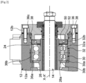
Fig 2 ] est une vue en coupe partielle du vérin électromécanique de lafigure 1 selon un autre plan de coupe, - [
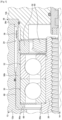
Fig 3 ] est une vue de détail de lafigure 2 , et - [
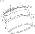
Fig 4 ] est une vue en perspective d'un fourreau du vérin électromécanique desfigures 1 et2 . - Sur la
figure 1 un vérin électromécanique, désigné par la référence numérique générale 10, d'axe X-X' longitudinal, est représenté dans une position supposée horizontale. - Le vérin 10 comprend un carter 12, une tige 14 d'actionnement mobile axialement et coaxiale à l'axe X-X', un moteur 16 électrique et un mécanisme 18 de transformation d'un mouvement de rotation dudit moteur en mouvement translation linéaire de la tige 14 le long de l'axe X-X'. Le mécanisme 18 est interposé radialement entre le moteur 16 électrique et la tige d'actionnement 14.
- Le moteur 16 électrique et le mécanisme 18 sont entièrement logés à l'intérieur du carter 12. La tige 14 d'actionnement s'étend axialement à travers le carter 12 et en saillie vers l'extérieur.
- Le moteur 16 électrique comprend un stator 20 fixé sur le carter 12 et un rotor (non représenté). Le stator 20 est fixé dans l'alésage 24 du carter. Le rotor est pourvu d'un arbre 26 de rotor tubulaire et d'une pluralité d'aimants (non représentés) permanents supportés par ledit arbre. L'arbre 26 de rotor s'étend axialement de part et d'autre du stator 20. Le moteur 16 électrique peut être du type brushless.
- Dans l'exemple de réalisation illustré, le carter 12 comprend un corps 12a principal tubulaire, et des flasques avant 12b et arrière 12c fixés chacun à une extrémité axiale dudit corps. La tige 14 d'actionnement s'étend à travers le flasque avant 12b et en saillie à l'extérieur du carter 12. Le corps 12a principal délimite la majeure partie de l'alésage 24 du carter.
- Pour guider en rotation et supporter l'arbre 26 de rotor, le vérin 10 comprend encore deux paliers 30, 32 à roulement avant et un palier 34 à roulement arrière.
- Le palier 34 à roulement arrière est interposé radialement entre l'arbre 26 de rotor et un support 35 arrière du carter interposé axialement entre le corps 12a et le flasque arrière 12c. Le palier 34 à roulement est monté sur la surface extérieure de l'arbre 26 de rotor du moteur électrique et dans un alésage du support 35 arrière.
- Comme cela sera décrit plus en détail par la suite, le vérin 10 comprend également un boitier formant fourreau 36 à l'intérieur duquel sont montés les paliers 30, 32 à roulement avant et qui supporte des capteurs 38 d'effort (
figure 2 ) dudit vérin. Le fourreau 36 est fixé au carter 12. Le fourreau 36 est interposé radialement entre l'alésage 24 du carter et les paliers 30, 32. - Dans l'exemple de réalisation illustré, le mécanisme 18 est un mécanisme de vis à rouleaux du type vis à rouleaux satellites inversée. Le mécanisme 18 comprend une vis 40, qui est coaxiale à la tige 14 d'actionnement, fixée à ladite tige et pourvue d'un filetage extérieur (non référencé), et une pluralité de rouleaux 42 longitudinaux disposés radialement entre la vis et l'arbre 26 de rotor du moteur électrique. L'arbre 26 de rotor présente une forme tubulaire. L'arbre 26 de rotor, coaxial à la vis 40, comprend un filetage intérieur (non référencé) dont le diamètre intérieur est supérieur au diamètre extérieur du filetage de la vis 40.
- Les rouleaux 42 sont identiques entre eux et répartis ici de manière régulière autour de la vis 40. Chaque rouleau 42 s'étend selon un axe parallèle à l'axe de la vis et comprend un filetage extérieur (non référencé) en prise avec le filetage extérieur de la vis 40 et avec le filetage intérieur de l'arbre 26 de rotor. De manière connue en soi, chaque rouleau 42 comprend, à chaque extrémité, une denture extérieure en prise avec une denture de synchronisation de la vis 40, et un tourillon s'étendant axialement vers l'extérieur à partir de la denture et logé dans un évidement d'une des bagues 44, 46 d'espacement montées sur ladite vis.
- La tige 14 d'actionnement est solidaire de la vis 40 du mécanisme de vis à rouleaux. Une rotation de l'arbre 26 de rotor du moteur électrique est convertie en une translation de la vis 40 et de la tige 14 d'actionnement le long de l'axe X-X'.
- Comme indiqué précédemment, les paliers 30, 32 supportent et assurent le guidage en rotation de l'arbre 26 de rotor du moteur électrique. Les paliers 30, 32 sont montés axialement en appui l'un contre l'autre.
- Comme illustré plus visiblement à la
figure 2 , chaque palier 30, 32 comprend une bague extérieure 30a, 32a, une bague intérieure 30b, 32b et une pluralité d'éléments roulants 30c, 32c, ici réalisés sous la forme d'une rangée de billes, disposés radialement entre des chemins de roulement formés sur lesdites bagues. Chaque palier 30, 32 comprend également une cage (non représentée) de maintien de l'espacement circonférentiel régulier des éléments roulants. - La bague intérieure 30b, 32b de chaque palier est montée sur la surface extérieure de l'arbre 26 de rotor du moteur électrique. La bague extérieure 30a, 32a de chaque palier est montée à l'intérieur de l'alésage du fourreau 36.
- La bague intérieure 30b du palier 30 est montée axialement en appui contre un épaulement 26a de l'arbre de rotor. La bague extérieure 30a de ce palier 30 est montée axialement en appui contre un rebord 36a radial annulaire du fourreau 36, ici par l'intermédiaire d'une rondelle (non référencée). Alternativement, il est possible de prévoir un contact direct entre le rebord 36a du fourreau et la bague extérieure 30a.
- Pour précharger axialement l'empilement des paliers 30 et 32, le vérin 10 comprend deux écrous 50, 52 de blocage montés respectivement en appui contre les bagues intérieure 32b et extérieure 32a du palier 32, axialement du côté opposé à l'autre palier 30. Une rondelle (non référencée) est ici axialement interposée entre chaque écrou 50, 52 et le palier 32. Alternativement, il est possible de ne pas prévoir ces rondelles. L'écrou 50 est vissé sur la surface extérieure de l'arbre 26 de rotor du moteur électrique. L'écrou 52 est quant à lui vissé dans l'alésage du fourreau 36.
- Comme indiqué précédemment, les paliers 30, 32 sont montés à l'intérieur du fourreau 36 qui supporte également les capteurs 38 d'effort. Le fourreau 36 est réalisé en une seule pièce. Le fourreau 36 peut par exemple être réalisé en matière métallique, notamment en acier.
- Le fourreau 36 comprend une portion tubulaire 36b axiale délimitant l'alésage dudit fourreau à l'intérieur duquel sont montés les paliers 30, 32. A une extrémité axiale, la portion tubulaire 36b est prolongée radialement vers l'intérieur par le rebord 36a. A l'extrémité axiale opposée, la portion tubulaire 36b est prolongée radialement vers l'extérieur par une bride 36c radiale annulaire. La bride 36c est enserrée axialement entre le corps 12a et le flasque avant 12b du carter. La bride 36c assure la fixation du fourreau 36 au carter 12.
- Les capteurs 38 d'effort sont montés sur la portion tubulaire 36b du fourreau. Les capteurs 38 d'effort sont montés sur la portion tubulaire 36b en étant décalés axialement par rapport aux paliers 30 et 32, ici du côté de la bride 36c. Les capteurs 38 ne sont pas situés radialement au droit de la zone de la portion tubulaire 36b à l'intérieur de laquelle sont montés les paliers 30, 32. Autrement dit, les capteurs 38 d'effort sont montés sur la portion tubulaire 36b dans une zone de celle-ci laissée libre par les paliers 30, 32.
- Dans l'exemple de réalisation illustré, les capteurs 38 d'effort sont montés sur la surface extérieure de la portion tubulaire 36b. Alternativement, il pourrait être possible de prévoir un montage des capteurs 38 d'effort dans l'alésage de la portion tubulaire 36b. Les capteurs 38 sont ici au nombre de deux et diamétralement opposés. En variante, il est possible de prévoir un nombre différent de capteurs, par exemple un unique capteur ou au moins trois capteurs. Dans le cas d'une pluralité de capteurs, ceux-ci sont de préférence espacés de manière régulière les uns par rapport aux autres dans le sens circonférentiel.
- Les capteurs 38 d'effort sont des jauges de déformation dont la résistance varie avec la force axiale appliquée sur le fourreau 36. Les capteurs 38 d'effort sont aptes à se déformer de sorte à pouvoir mesurer une compression ou un allongement axial de la portion tubulaire 36b du fourreau. Dans l'exemple de réalisation illustré, deux portions planes opposées sont formées sur la portion tubulaire 36b du fourreau pour le montage des capteurs 38 d'effort.
- Comme cela est illustré plus visiblement à la
figure 4 , des ouvertures 54 traversantes sont ménagées dans l'épaisseur radiale de la portion tubulaire 36b du fourreau. Ces ouvertures 54 sont prévues pour favoriser les déformations de la portion tubulaire 36b du fourreau dans la zone des capteurs 38 d'effort. Chaque capteur 38 d'effort est disposé entre deux ouvertures 54 successives dans le sens circonférentiel. Les capteurs 38 d'effort et les ouvertures 54 sont situés dans un même plan radial. Les capteurs 38 d'effort et les ouvertures 54 sont ici disposés axialement à proximité de la bride 36c du fourreau. - Dans l'exemple de réalisation illustré, sur la portion tubulaire 36b du fourreau sont également prévues des gorges 56, 58 pour le montage de câbles de connexion électrique (non représentés) qui relient les capteurs 38 d'effort à une carte électronique 60 (
figure 1 ) du vérin électronique pour le traitement des signaux émis. Les gorges 56, 58 sont formées sur la surface extérieure de la portion tubulaire 36b du fourreau. Dans l'exemple de réalisation illustré, la gorge 56 s'étend dans le sens circonférentiel et est de forme annulaire. La gorge 58 s'étend quant à elle axialement et débouche dans la gorge 56. Les câbles de connexion électrique peuvent être fixés à l'intérieur des gorges 56, 58 par tout moyen approprié, par exemple par collage. En variante, il pourrait être possible de ne pas prévoir de telles gorges. - En se référant de nouveau à la
figure 1 , la carte électronique 60 est fixée à l'intérieur d'un boitier 62 externe qui est lui-même fixé au carter 12. Un évidement 64 traversant est ménagé dans l'épaisseur du corps 12a du carter pour le passage des câbles de connexion électrique. - En se référant à la
figure 3 , un jeu radial 66 annulaire est prévu entre l'alésage 24 du carter et la portion tubulaire 36b du fourreau. Il n'existe aucun contact direct dans le sens radial entre la portion tubulaire 36b du fourreau et l'alésage 24 du carter dans les zones de montage des paliers 30, 32 et des capteurs 38 d'effort. Le jeu radial 66 annulaire est prévu ici le long de la totalité de la portion tubulaire 36b du fourreau. Un jeu axial 68 est également prévu entre l'alésage 24 du carter et le rebord 36c du fourreau. - La portion tubulaire 36b du fourreau est montée flottante par rapport au carter 12. Aucun contact direct n'est prévu ici dans le sens axial et dans le sens radial entre la portion tubulaire 36b du fourreau et l'alésage 24 du carter.
- En fonctionnement, lors des mouvements où la tige 14 du vérin pousse une charge et travaille en compression, l'effort est repris par le palier 32 puis par le palier 30 en appui contre le rebord 36a du fourreau, ce qui provoque un allongement de la portion tubulaire 36b dudit fourreau, notamment dans la zone des capteurs 38 d'effort qui mesurent cet allongement.
- A l'inverse, lors des mouvements où la tige 14 du vérin tire une charge et travaille en traction, l'effort est repris par le palier 30 puis par le palier 32 en appui contre l'écrou 52, ce qui provoque une compression de la portion tubulaire 36b du fourreau qui est mesurée par les capteurs 38 d'effort.
- Grâce à la prévision du fourreau 36 intermédiaire sur lequel sont montés les capteurs 38 d'effort et au positionnement de ces capteurs relativement aux paliers 30 et 32, la précision des mesures obtenues est améliorée, et ce, avec une même sensibilité quel que soit le sens de l'effort appliqué sur le fourreau et la fixation du vérin électromécanique avec son environnement extérieur.
- L'invention a été illustrée ici sur la base d'un vérin comprenant des paliers 30, 32 du type à billes à contact oblique. Alternativement, il pourrait être possible de prévoir d'autres types d'éléments roulants, par exemples des rouleaux.
- Dans les exemples de réalisation illustrés, les éléments roulants sont disposés en O. Alternativement, il pourrait être possible de prévoir une disposition en X.
- L'invention a été illustrée sur la base d'un vérin comprenant des paliers montés axialement en appui l'un contre l'autre et comprenant chacun une unique rangée d'éléments roulants. En variante, il pourrait par exemple être possible de prévoir un unique palier comprenant au moins deux rangées d'éléments roulants, ou encore un nombre supérieur de paliers empilés axialement et comprenant chacun une ou plusieurs rangées d'éléments roulants.
Claims (8)
- Vérin électromécanique comprenant un carter (12), une tige d'actionnement (14) montée mobile longitudinalement par rapport au carter, un moteur électrique (16) pourvu d'un arbre de rotor (26) rotatif, un mécanisme (18) de transformation d'un mouvement de rotation de l'arbre de rotor du moteur électrique en un mouvement de translation linéaire de la tige d'actionnement, et au moins un palier (30) pour guider en rotation l'arbre de rotor (26) du moteur électrique par rapport au carter (12) et pour supporter l'arbre de rotor, dans lequel le vérin comprend en outre un fourreau (36) fixé au carter (12) et à l'intérieur duquel est monté ledit palier (30), et au moins un capteur d'effort (38) monté sur le fourreau (36) en étant décalé axialement par rapport audit palier (30),
caractérisé en ce que
le carter (12) comprend un corps principal (12a) tubulaire et des flasques avant (12b) et arrière (12c) montés chacun à une extrémité du corps principal, la tige d'actionnement (14) s'étendant à travers le flasque avant (12b) et ledit palier (30) étant situé axialement entre le moteur électrique (16) et le flasque avant (12b), dans lequel le fourreau (36) comprend une portion tubulaire (36b) axiale à l'intérieur de laquelle est monté ledit palier (30) et supportant ledit capteur d'effort (38) et une bride (36c) radiale pour la fixation dudit fourreau au carter (12) dans lequel la bride (36c) du fourreau est enserrée axialement entre le corps principal (12a) et le flasque avant (12b) du carter. - Vérin selon la revendication 1, dans lequel un jeu radial (66) annulaire est prévu au moins entre l'alésage du carter (12) et la portion du fourreau sur laquelle sont montés ledit palier (30) et ledit capteur (38).
- Vérin selon l'une quelconque revendications précédentes, dans lequel un jeu axial (68) annulaire est prévu entre l'alésage du carter (12) et l'extrémité du fourreau (36) située axialement à l'opposé de la bride (36c).
- Vérin selon l'une quelconque des revendications précédentes, dans lequel des ouvertures (54) traversantes sont ménagées dans l'épaisseur radiale du fourreau (36), ledit capteur d'effort (38) étant disposé entre deux ouvertures (54) successives dans le sens circonférentiel.
- Vérin selon l'une quelconque des revendications précédentes, comprenant au moins un câble de connexion électrique qui est relié audit capteur d'effort (38) et qui est monté sur le fourreau (36).
- Vérin selon la revendication 5, dans lequel ledit câble de connexion électrique s'étend au moins en partie à l'intérieur d'au moins une gorge (56, 58) formée sur le fourreau.
- Vérin selon la revendication 5 ou 6, comprenant en outre une carte électronique (60) reliée audit câble de connexion électrique et qui est montée à l'intérieur d'un boitier (62) externe fixé au carter (12).
- Vérin selon l'une quelconque des revendications précédentes, dans lequel le mécanisme (18) de transformation de mouvement comprend une vis (40) solidaire de la tige d'actionnement (14) et pourvue d'un filetage extérieur, et une pluralité de rouleaux (42) longitudinaux en prise avec le filetage extérieur de la vis et avec un filetage intérieur de l'arbre de rotor (26) du moteur électrique.
Applications Claiming Priority (1)
| Application Number | Priority Date | Filing Date | Title |
|---|---|---|---|
| FR1906528A FR3097606B1 (fr) | 2019-06-18 | 2019-06-18 | Vérin électromécanique à capteur d’effort intégré |
Publications (2)
| Publication Number | Publication Date |
|---|---|
| EP3754225A1 EP3754225A1 (fr) | 2020-12-23 |
| EP3754225B1 true EP3754225B1 (fr) | 2023-09-06 |
Family
ID=67660366
Family Applications (1)
| Application Number | Title | Priority Date | Filing Date |
|---|---|---|---|
| EP20180434.1A Active EP3754225B1 (fr) | 2019-06-18 | 2020-06-17 | Vérin électromécanique à capteur d'effort intégré |
Country Status (4)
| Country | Link |
|---|---|
| US (1) | US11561142B2 (fr) |
| EP (1) | EP3754225B1 (fr) |
| CN (1) | CN112104146B (fr) |
| FR (1) | FR3097606B1 (fr) |
Families Citing this family (7)
| Publication number | Priority date | Publication date | Assignee | Title |
|---|---|---|---|---|
| JP7456883B2 (ja) * | 2020-07-31 | 2024-03-27 | ミネベアミツミ株式会社 | 転がり軸受ホルダユニット |
| US11685427B2 (en) * | 2021-04-12 | 2023-06-27 | Toyota Material Handling, Inc. | Electric actuator steering system for forklifts |
| US11616416B2 (en) * | 2021-05-05 | 2023-03-28 | Nidec Motor Corporation | Electric linear actuator with optimized coupling |
| EP4178089B1 (fr) | 2021-11-03 | 2024-02-14 | Diakont S.r.l. | Actionneur électromécanique linéaire |
| FR3133417B1 (fr) * | 2022-03-10 | 2024-07-05 | Ntn Snr Roulements | Système de transmission d’un couple moteur |
| DE102022111965A1 (de) | 2022-05-12 | 2023-11-16 | Ewellix AB | Linearantrieb und Hubtisch |
| CN121605254A (zh) * | 2023-07-28 | 2026-03-03 | 捷太格特轴承北美有限公司 | 具有集成感测能力的螺旋型致动器 |
Citations (2)
| Publication number | Priority date | Publication date | Assignee | Title |
|---|---|---|---|---|
| WO2007100338A1 (fr) * | 2006-03-03 | 2007-09-07 | Flowserve Management Company | Procédé et dispositif de mesure de charges |
| EP2258509B1 (fr) * | 2009-06-02 | 2014-07-16 | Obara Corporation | Unité de commande pour un dispositif de pression avec une cellule de charge piézoélectrique |
Family Cites Families (8)
| Publication number | Priority date | Publication date | Assignee | Title |
|---|---|---|---|---|
| NL1006543C2 (nl) * | 1997-07-10 | 1999-01-12 | Skf Ind Trading & Dev | Elektrische actuator en remklauw met een dergelijke actuator. |
| US7541707B2 (en) * | 2004-01-08 | 2009-06-02 | Tol-O-Matic, Inc. | Electric actuator |
| FR2869168B1 (fr) | 2004-04-14 | 2006-06-23 | Transrol Soc Par Actions Simpl | Verin d'actionnement a capteur associe a sa tige |
| WO2007088691A1 (fr) * | 2006-01-31 | 2007-08-09 | Thk Co., Ltd. | Dispositif d'entraînement de moteur électrique creux |
| US20070295110A1 (en) * | 2006-05-09 | 2007-12-27 | Keith Hochhalter | Load cell |
| DE102012208890A1 (de) * | 2012-05-25 | 2013-11-28 | Robert Bosch Gmbh | Handwerkzeugmaschine |
| US10060550B2 (en) * | 2013-11-21 | 2018-08-28 | Aktiebolaget Skf | Valve operator assembly with friction means and pre-stressing element |
| CN105429351A (zh) * | 2015-12-14 | 2016-03-23 | 重庆东登科技有限公司 | 行程可控的电动直线驱动器 |
-
2019
- 2019-06-18 FR FR1906528A patent/FR3097606B1/fr not_active Expired - Fee Related
-
2020
- 2020-06-09 CN CN202010517599.1A patent/CN112104146B/zh active Active
- 2020-06-17 US US16/903,620 patent/US11561142B2/en active Active
- 2020-06-17 EP EP20180434.1A patent/EP3754225B1/fr active Active
Patent Citations (2)
| Publication number | Priority date | Publication date | Assignee | Title |
|---|---|---|---|---|
| WO2007100338A1 (fr) * | 2006-03-03 | 2007-09-07 | Flowserve Management Company | Procédé et dispositif de mesure de charges |
| EP2258509B1 (fr) * | 2009-06-02 | 2014-07-16 | Obara Corporation | Unité de commande pour un dispositif de pression avec une cellule de charge piézoélectrique |
Also Published As
| Publication number | Publication date |
|---|---|
| US11561142B2 (en) | 2023-01-24 |
| FR3097606A1 (fr) | 2020-12-25 |
| US20200400517A1 (en) | 2020-12-24 |
| EP3754225A1 (fr) | 2020-12-23 |
| CN112104146B (zh) | 2023-11-10 |
| FR3097606B1 (fr) | 2022-07-22 |
| CN112104146A (zh) | 2020-12-18 |
Similar Documents
| Publication | Publication Date | Title |
|---|---|---|
| EP3754225A1 (fr) | Vérin électromécanique à capteur d'effort intégré | |
| EP1037051B1 (fr) | Palier à roulement instrumenté | |
| EP1452753B1 (fr) | Palier à roulement instrumenté | |
| FR3041830A1 (fr) | Verin electromecanique | |
| EP1330630B1 (fr) | Palier a roulement instrumente pour volant de commande | |
| EP1252524B1 (fr) | Dispositif de palier a roulement instrumente avec pre-indexation angulaire temporaire du codeur par rapport au capteur | |
| FR2946108A1 (fr) | Roulement instrumente, ensemble de roulement et machine electrique tournante comprenant un tel roulement ou un tel ensemble. | |
| FR2999674A1 (fr) | Systeme comprenant une vis a rouleaux | |
| FR2993330A1 (fr) | Systeme mecanique a embrayage unidirectionnel et alternateur comprenant un tel systeme | |
| EP1696217B1 (fr) | Dispositif de galet tendeur de courroie instrumenté et procédé de contrôle associé | |
| FR2993331A1 (fr) | Systeme mecanique a embrayage unidirectionnel et alternateur comprenant un tel systeme | |
| FR3137730A1 (fr) | Palier pour moteur ou machine électrique | |
| WO2000063059A1 (fr) | Dispositif de rappel au point neutre, en particulier pour volant | |
| EP4214822A1 (fr) | Rotor pour moteur électrique équipé d'un circuit électronique | |
| EP3784917A1 (fr) | Palier à roulement | |
| EP3631222A1 (fr) | Moto-reducteur pour systeme d'essuyage de vehicule automobile | |
| FR2882139A1 (fr) | Dispositif de detection des parametres de rotation de deux elements | |
| FR3080656A1 (fr) | Palier a roulement | |
| FR3127034A1 (fr) | Systeme d’accouplement en rotation sans jeu entre deux arbres | |
| EP0546918B1 (fr) | Roulement préassemblé à éléments codeur et capteur additionnels | |
| EP1473570A1 (fr) | Roulement équipé d'un dispositif intégré de détection de la vitesse de rotation | |
| FR3161930A1 (fr) | Dispositif de palier à isolation électrique intégrée, notamment pour moteur ou machine électrique | |
| FR3122227A1 (fr) | Doublon de roulements amélioré | |
| EP4111532A1 (fr) | Support d'antenne mobile | |
| FR2879707A1 (fr) | Dispositif de galet tendeur de courroie instrumente et procede de controle associe |
Legal Events
| Date | Code | Title | Description |
|---|---|---|---|
| PUAI | Public reference made under article 153(3) epc to a published international application that has entered the european phase |
Free format text: ORIGINAL CODE: 0009012 |
|
| STAA | Information on the status of an ep patent application or granted ep patent |
Free format text: STATUS: THE APPLICATION HAS BEEN PUBLISHED |
|
| AK | Designated contracting states |
Kind code of ref document: A1 Designated state(s): AL AT BE BG CH CY CZ DE DK EE ES FI FR GB GR HR HU IE IS IT LI LT LU LV MC MK MT NL NO PL PT RO RS SE SI SK SM TR |
|
| AX | Request for extension of the european patent |
Extension state: BA ME |
|
| STAA | Information on the status of an ep patent application or granted ep patent |
Free format text: STATUS: REQUEST FOR EXAMINATION WAS MADE |
|
| 17P | Request for examination filed |
Effective date: 20210305 |
|
| RBV | Designated contracting states (corrected) |
Designated state(s): AL AT BE BG CH CY CZ DE DK EE ES FI FR GB GR HR HU IE IS IT LI LT LU LV MC MK MT NL NO PL PT RO RS SE SI SK SM TR |
|
| STAA | Information on the status of an ep patent application or granted ep patent |
Free format text: STATUS: EXAMINATION IS IN PROGRESS |
|
| 17Q | First examination report despatched |
Effective date: 20211214 |
|
| RAP3 | Party data changed (applicant data changed or rights of an application transferred) |
Owner name: EWELLIX AB |
|
| RIC1 | Information provided on ipc code assigned before grant |
Ipc: F16H 25/22 20060101ALN20230406BHEP Ipc: H02K 7/08 20060101ALI20230406BHEP Ipc: G01L 5/00 20060101ALI20230406BHEP Ipc: H02K 7/06 20060101ALI20230406BHEP Ipc: F16H 25/20 20060101AFI20230406BHEP |
|
| GRAP | Despatch of communication of intention to grant a patent |
Free format text: ORIGINAL CODE: EPIDOSNIGR1 |
|
| STAA | Information on the status of an ep patent application or granted ep patent |
Free format text: STATUS: GRANT OF PATENT IS INTENDED |
|
| INTG | Intention to grant announced |
Effective date: 20230519 |
|
| P01 | Opt-out of the competence of the unified patent court (upc) registered |
Effective date: 20230514 |
|
| GRAS | Grant fee paid |
Free format text: ORIGINAL CODE: EPIDOSNIGR3 |
|
| GRAA | (expected) grant |
Free format text: ORIGINAL CODE: 0009210 |
|
| STAA | Information on the status of an ep patent application or granted ep patent |
Free format text: STATUS: THE PATENT HAS BEEN GRANTED |
|
| AK | Designated contracting states |
Kind code of ref document: B1 Designated state(s): AL AT BE BG CH CY CZ DE DK EE ES FI FR GB GR HR HU IE IS IT LI LT LU LV MC MK MT NL NO PL PT RO RS SE SI SK SM TR |
|
| REG | Reference to a national code |
Ref country code: GB Ref legal event code: FG4D Free format text: NOT ENGLISH |
|
| REG | Reference to a national code |
Ref country code: CH Ref legal event code: EP |
|
| REG | Reference to a national code |
Ref country code: IE Ref legal event code: FG4D Free format text: LANGUAGE OF EP DOCUMENT: FRENCH |
|
| REG | Reference to a national code |
Ref country code: DE Ref legal event code: R096 Ref document number: 602020017052 Country of ref document: DE |
|
| REG | Reference to a national code |
Ref country code: LT Ref legal event code: MG9D |
|
| REG | Reference to a national code |
Ref country code: NL Ref legal event code: MP Effective date: 20230906 |
|
| PG25 | Lapsed in a contracting state [announced via postgrant information from national office to epo] |
Ref country code: GR Free format text: LAPSE BECAUSE OF FAILURE TO SUBMIT A TRANSLATION OF THE DESCRIPTION OR TO PAY THE FEE WITHIN THE PRESCRIBED TIME-LIMIT Effective date: 20231207 |
|
| PG25 | Lapsed in a contracting state [announced via postgrant information from national office to epo] |
Ref country code: SE Free format text: LAPSE BECAUSE OF FAILURE TO SUBMIT A TRANSLATION OF THE DESCRIPTION OR TO PAY THE FEE WITHIN THE PRESCRIBED TIME-LIMIT Effective date: 20230906 Ref country code: RS Free format text: LAPSE BECAUSE OF FAILURE TO SUBMIT A TRANSLATION OF THE DESCRIPTION OR TO PAY THE FEE WITHIN THE PRESCRIBED TIME-LIMIT Effective date: 20230906 Ref country code: NO Free format text: LAPSE BECAUSE OF FAILURE TO SUBMIT A TRANSLATION OF THE DESCRIPTION OR TO PAY THE FEE WITHIN THE PRESCRIBED TIME-LIMIT Effective date: 20231206 Ref country code: LV Free format text: LAPSE BECAUSE OF FAILURE TO SUBMIT A TRANSLATION OF THE DESCRIPTION OR TO PAY THE FEE WITHIN THE PRESCRIBED TIME-LIMIT Effective date: 20230906 Ref country code: LT Free format text: LAPSE BECAUSE OF FAILURE TO SUBMIT A TRANSLATION OF THE DESCRIPTION OR TO PAY THE FEE WITHIN THE PRESCRIBED TIME-LIMIT Effective date: 20230906 Ref country code: HR Free format text: LAPSE BECAUSE OF FAILURE TO SUBMIT A TRANSLATION OF THE DESCRIPTION OR TO PAY THE FEE WITHIN THE PRESCRIBED TIME-LIMIT Effective date: 20230906 Ref country code: GR Free format text: LAPSE BECAUSE OF FAILURE TO SUBMIT A TRANSLATION OF THE DESCRIPTION OR TO PAY THE FEE WITHIN THE PRESCRIBED TIME-LIMIT Effective date: 20231207 Ref country code: FI Free format text: LAPSE BECAUSE OF FAILURE TO SUBMIT A TRANSLATION OF THE DESCRIPTION OR TO PAY THE FEE WITHIN THE PRESCRIBED TIME-LIMIT Effective date: 20230906 |
|
| REG | Reference to a national code |
Ref country code: AT Ref legal event code: MK05 Ref document number: 1608934 Country of ref document: AT Kind code of ref document: T Effective date: 20230906 |
|
| PG25 | Lapsed in a contracting state [announced via postgrant information from national office to epo] |
Ref country code: NL Free format text: LAPSE BECAUSE OF FAILURE TO SUBMIT A TRANSLATION OF THE DESCRIPTION OR TO PAY THE FEE WITHIN THE PRESCRIBED TIME-LIMIT Effective date: 20230906 |
|
| PG25 | Lapsed in a contracting state [announced via postgrant information from national office to epo] |
Ref country code: IS Free format text: LAPSE BECAUSE OF FAILURE TO SUBMIT A TRANSLATION OF THE DESCRIPTION OR TO PAY THE FEE WITHIN THE PRESCRIBED TIME-LIMIT Effective date: 20240106 |
|
| PG25 | Lapsed in a contracting state [announced via postgrant information from national office to epo] |
Ref country code: AT Free format text: LAPSE BECAUSE OF FAILURE TO SUBMIT A TRANSLATION OF THE DESCRIPTION OR TO PAY THE FEE WITHIN THE PRESCRIBED TIME-LIMIT Effective date: 20230906 |
|
| PG25 | Lapsed in a contracting state [announced via postgrant information from national office to epo] |
Ref country code: ES Free format text: LAPSE BECAUSE OF FAILURE TO SUBMIT A TRANSLATION OF THE DESCRIPTION OR TO PAY THE FEE WITHIN THE PRESCRIBED TIME-LIMIT Effective date: 20230906 |
|
| PG25 | Lapsed in a contracting state [announced via postgrant information from national office to epo] |
Ref country code: SM Free format text: LAPSE BECAUSE OF FAILURE TO SUBMIT A TRANSLATION OF THE DESCRIPTION OR TO PAY THE FEE WITHIN THE PRESCRIBED TIME-LIMIT Effective date: 20230906 Ref country code: RO Free format text: LAPSE BECAUSE OF FAILURE TO SUBMIT A TRANSLATION OF THE DESCRIPTION OR TO PAY THE FEE WITHIN THE PRESCRIBED TIME-LIMIT Effective date: 20230906 Ref country code: IS Free format text: LAPSE BECAUSE OF FAILURE TO SUBMIT A TRANSLATION OF THE DESCRIPTION OR TO PAY THE FEE WITHIN THE PRESCRIBED TIME-LIMIT Effective date: 20240106 Ref country code: ES Free format text: LAPSE BECAUSE OF FAILURE TO SUBMIT A TRANSLATION OF THE DESCRIPTION OR TO PAY THE FEE WITHIN THE PRESCRIBED TIME-LIMIT Effective date: 20230906 Ref country code: EE Free format text: LAPSE BECAUSE OF FAILURE TO SUBMIT A TRANSLATION OF THE DESCRIPTION OR TO PAY THE FEE WITHIN THE PRESCRIBED TIME-LIMIT Effective date: 20230906 Ref country code: CZ Free format text: LAPSE BECAUSE OF FAILURE TO SUBMIT A TRANSLATION OF THE DESCRIPTION OR TO PAY THE FEE WITHIN THE PRESCRIBED TIME-LIMIT Effective date: 20230906 Ref country code: AT Free format text: LAPSE BECAUSE OF FAILURE TO SUBMIT A TRANSLATION OF THE DESCRIPTION OR TO PAY THE FEE WITHIN THE PRESCRIBED TIME-LIMIT Effective date: 20230906 Ref country code: SK Free format text: LAPSE BECAUSE OF FAILURE TO SUBMIT A TRANSLATION OF THE DESCRIPTION OR TO PAY THE FEE WITHIN THE PRESCRIBED TIME-LIMIT Effective date: 20230906 Ref country code: PT Free format text: LAPSE BECAUSE OF FAILURE TO SUBMIT A TRANSLATION OF THE DESCRIPTION OR TO PAY THE FEE WITHIN THE PRESCRIBED TIME-LIMIT Effective date: 20240108 |
|
| PG25 | Lapsed in a contracting state [announced via postgrant information from national office to epo] |
Ref country code: PL Free format text: LAPSE BECAUSE OF FAILURE TO SUBMIT A TRANSLATION OF THE DESCRIPTION OR TO PAY THE FEE WITHIN THE PRESCRIBED TIME-LIMIT Effective date: 20230906 Ref country code: IT Free format text: LAPSE BECAUSE OF FAILURE TO SUBMIT A TRANSLATION OF THE DESCRIPTION OR TO PAY THE FEE WITHIN THE PRESCRIBED TIME-LIMIT Effective date: 20230906 |
|
| REG | Reference to a national code |
Ref country code: DE Ref legal event code: R097 Ref document number: 602020017052 Country of ref document: DE |
|
| REG | Reference to a national code |
Ref country code: DE Ref legal event code: R081 Ref document number: 602020017052 Country of ref document: DE Owner name: SCHAEFFLER TECHNOLOGIES AG & CO. KG, DE Free format text: FORMER OWNER: EWELLIX AB, PARTILLE, GOETEBORG, SE Ref country code: DE Ref document number: 602020017052 Country of ref document: DE Ref country code: DE Ref legal event code: R082 Ref document number: 602020017052 Country of ref document: DE Representative=s name: HEYERHOFF GEIGER GMBH & CO. KG, DE |
|
| PG25 | Lapsed in a contracting state [announced via postgrant information from national office to epo] |
Ref country code: DK Free format text: LAPSE BECAUSE OF FAILURE TO SUBMIT A TRANSLATION OF THE DESCRIPTION OR TO PAY THE FEE WITHIN THE PRESCRIBED TIME-LIMIT Effective date: 20230906 |
|
| PLBE | No opposition filed within time limit |
Free format text: ORIGINAL CODE: 0009261 |
|
| STAA | Information on the status of an ep patent application or granted ep patent |
Free format text: STATUS: NO OPPOSITION FILED WITHIN TIME LIMIT |
|
| PG25 | Lapsed in a contracting state [announced via postgrant information from national office to epo] |
Ref country code: DK Free format text: LAPSE BECAUSE OF FAILURE TO SUBMIT A TRANSLATION OF THE DESCRIPTION OR TO PAY THE FEE WITHIN THE PRESCRIBED TIME-LIMIT Effective date: 20230906 Ref country code: SI Free format text: LAPSE BECAUSE OF FAILURE TO SUBMIT A TRANSLATION OF THE DESCRIPTION OR TO PAY THE FEE WITHIN THE PRESCRIBED TIME-LIMIT Effective date: 20230906 |
|
| 26N | No opposition filed |
Effective date: 20240607 |
|
| PG25 | Lapsed in a contracting state [announced via postgrant information from national office to epo] |
Ref country code: BG Free format text: LAPSE BECAUSE OF FAILURE TO SUBMIT A TRANSLATION OF THE DESCRIPTION OR TO PAY THE FEE WITHIN THE PRESCRIBED TIME-LIMIT Effective date: 20230906 |
|
| PG25 | Lapsed in a contracting state [announced via postgrant information from national office to epo] |
Ref country code: BG Free format text: LAPSE BECAUSE OF FAILURE TO SUBMIT A TRANSLATION OF THE DESCRIPTION OR TO PAY THE FEE WITHIN THE PRESCRIBED TIME-LIMIT Effective date: 20230906 |
|
| PG25 | Lapsed in a contracting state [announced via postgrant information from national office to epo] |
Ref country code: MC Free format text: LAPSE BECAUSE OF FAILURE TO SUBMIT A TRANSLATION OF THE DESCRIPTION OR TO PAY THE FEE WITHIN THE PRESCRIBED TIME-LIMIT Effective date: 20230906 |
|
| REG | Reference to a national code |
Ref country code: CH Ref legal event code: PL |
|
| PG25 | Lapsed in a contracting state [announced via postgrant information from national office to epo] |
Ref country code: LU Free format text: LAPSE BECAUSE OF NON-PAYMENT OF DUE FEES Effective date: 20240617 |
|
| GBPC | Gb: european patent ceased through non-payment of renewal fee |
Effective date: 20240617 |
|
| PG25 | Lapsed in a contracting state [announced via postgrant information from national office to epo] |
Ref country code: IE Free format text: LAPSE BECAUSE OF NON-PAYMENT OF DUE FEES Effective date: 20240617 |
|
| PG25 | Lapsed in a contracting state [announced via postgrant information from national office to epo] |
Ref country code: BE Free format text: LAPSE BECAUSE OF NON-PAYMENT OF DUE FEES Effective date: 20240630 Ref country code: CH Free format text: LAPSE BECAUSE OF NON-PAYMENT OF DUE FEES Effective date: 20240630 |
|
| PG25 | Lapsed in a contracting state [announced via postgrant information from national office to epo] |
Ref country code: GB Free format text: LAPSE BECAUSE OF NON-PAYMENT OF DUE FEES Effective date: 20240617 |
|
| REG | Reference to a national code |
Ref country code: DE Ref legal event code: R082 Ref document number: 602020017052 Country of ref document: DE Representative=s name: HEYERHOFF GEIGER GMBH & CO. KG, DE |
|
| REG | Reference to a national code |
Ref country code: BE Ref legal event code: MM Effective date: 20240630 |
|
| PGFP | Annual fee paid to national office [announced via postgrant information from national office to epo] |
Ref country code: FR Payment date: 20250626 Year of fee payment: 6 |
|
| PGFP | Annual fee paid to national office [announced via postgrant information from national office to epo] |
Ref country code: DE Payment date: 20250820 Year of fee payment: 6 |
|
| PG25 | Lapsed in a contracting state [announced via postgrant information from national office to epo] |
Ref country code: CY Free format text: LAPSE BECAUSE OF FAILURE TO SUBMIT A TRANSLATION OF THE DESCRIPTION OR TO PAY THE FEE WITHIN THE PRESCRIBED TIME-LIMIT; INVALID AB INITIO Effective date: 20200617 |
|
| PG25 | Lapsed in a contracting state [announced via postgrant information from national office to epo] |
Ref country code: HU Free format text: LAPSE BECAUSE OF FAILURE TO SUBMIT A TRANSLATION OF THE DESCRIPTION OR TO PAY THE FEE WITHIN THE PRESCRIBED TIME-LIMIT; INVALID AB INITIO Effective date: 20200617 |
|
| REG | Reference to a national code |
Ref country code: DE Ref legal event code: R082 Ref document number: 602020017052 Country of ref document: DE |