EP3754192B1 - Luftpumpe für ein aufblasbares produkt und aufblasbares produkt mit eingebauter luftpumpe - Google Patents
Luftpumpe für ein aufblasbares produkt und aufblasbares produkt mit eingebauter luftpumpe Download PDFInfo
- Publication number
- EP3754192B1 EP3754192B1 EP20180228.7A EP20180228A EP3754192B1 EP 3754192 B1 EP3754192 B1 EP 3754192B1 EP 20180228 A EP20180228 A EP 20180228A EP 3754192 B1 EP3754192 B1 EP 3754192B1
- Authority
- EP
- European Patent Office
- Prior art keywords
- air
- segment
- pump
- air pump
- knob switch
- Prior art date
- Legal status (The legal status is an assumption and is not a legal conclusion. Google has not performed a legal analysis and makes no representation as to the accuracy of the status listed.)
- Active
Links
Images













Classifications
-
- F—MECHANICAL ENGINEERING; LIGHTING; HEATING; WEAPONS; BLASTING
- F04—POSITIVE - DISPLACEMENT MACHINES FOR LIQUIDS; PUMPS FOR LIQUIDS OR ELASTIC FLUIDS
- F04B—POSITIVE-DISPLACEMENT MACHINES FOR LIQUIDS; PUMPS
- F04B35/00—Piston pumps specially adapted for elastic fluids and characterised by the driving means to their working members, or by combination with, or adaptation to, specific driving engines or motors, not otherwise provided for
- F04B35/04—Piston pumps specially adapted for elastic fluids and characterised by the driving means to their working members, or by combination with, or adaptation to, specific driving engines or motors, not otherwise provided for the means being electric
-
- F—MECHANICAL ENGINEERING; LIGHTING; HEATING; WEAPONS; BLASTING
- F04—POSITIVE - DISPLACEMENT MACHINES FOR LIQUIDS; PUMPS FOR LIQUIDS OR ELASTIC FLUIDS
- F04D—NON-POSITIVE-DISPLACEMENT PUMPS
- F04D25/00—Pumping installations or systems
- F04D25/02—Units comprising pumps and their driving means
- F04D25/06—Units comprising pumps and their driving means the pump being electrically driven
-
- A—HUMAN NECESSITIES
- A47—FURNITURE; DOMESTIC ARTICLES OR APPLIANCES; COFFEE MILLS; SPICE MILLS; SUCTION CLEANERS IN GENERAL
- A47C—CHAIRS; SOFAS; BEDS
- A47C27/00—Spring, stuffed or fluid mattresses or cushions specially adapted for chairs, beds or sofas
- A47C27/08—Fluid mattresses
- A47C27/081—Fluid mattresses of pneumatic type
- A47C27/082—Fluid mattresses of pneumatic type with non-manual inflation, e.g. with electric pumps
-
- B—PERFORMING OPERATIONS; TRANSPORTING
- B63—SHIPS OR OTHER WATERBORNE VESSELS; RELATED EQUIPMENT
- B63B—SHIPS OR OTHER WATERBORNE VESSELS; EQUIPMENT FOR SHIPPING
- B63B7/00—Collapsible, foldable, inflatable or like vessels
- B63B7/06—Collapsible, foldable, inflatable or like vessels having parts of non-rigid material
- B63B7/08—Inflatable
- B63B7/085—Accessories or mountings specially adapted therefor, e.g. seats, sailing kits, motor mountings
-
- F—MECHANICAL ENGINEERING; LIGHTING; HEATING; WEAPONS; BLASTING
- F04—POSITIVE - DISPLACEMENT MACHINES FOR LIQUIDS; PUMPS FOR LIQUIDS OR ELASTIC FLUIDS
- F04B—POSITIVE-DISPLACEMENT MACHINES FOR LIQUIDS; PUMPS
- F04B35/00—Piston pumps specially adapted for elastic fluids and characterised by the driving means to their working members, or by combination with, or adaptation to, specific driving engines or motors, not otherwise provided for
- F04B35/06—Mobile combinations
-
- F—MECHANICAL ENGINEERING; LIGHTING; HEATING; WEAPONS; BLASTING
- F04—POSITIVE - DISPLACEMENT MACHINES FOR LIQUIDS; PUMPS FOR LIQUIDS OR ELASTIC FLUIDS
- F04D—NON-POSITIVE-DISPLACEMENT PUMPS
- F04D25/00—Pumping installations or systems
- F04D25/02—Units comprising pumps and their driving means
- F04D25/08—Units comprising pumps and their driving means the working fluid being air, e.g. for ventilation
- F04D25/084—Units comprising pumps and their driving means the working fluid being air, e.g. for ventilation hand fans
-
- F—MECHANICAL ENGINEERING; LIGHTING; HEATING; WEAPONS; BLASTING
- F04—POSITIVE - DISPLACEMENT MACHINES FOR LIQUIDS; PUMPS FOR LIQUIDS OR ELASTIC FLUIDS
- F04D—NON-POSITIVE-DISPLACEMENT PUMPS
- F04D29/00—Details, component parts, or accessories
- F04D29/40—Casings; Connections of working fluid
- F04D29/42—Casings; Connections of working fluid for radial or helico-centrifugal pumps
- F04D29/44—Fluid-guiding means, e.g. diffusers
- F04D29/46—Fluid-guiding means, e.g. diffusers adjustable
- F04D29/50—Fluid-guiding means, e.g. diffusers adjustable for reversing fluid flow
- F04D29/503—Fluid-guiding means, e.g. diffusers adjustable for reversing fluid flow especially adapted for elastic fluid pumps
-
- A—HUMAN NECESSITIES
- A63—SPORTS; GAMES; AMUSEMENTS
- A63H—TOYS, e.g. TOPS, DOLLS, HOOPS OR BUILDING BLOCKS
- A63H33/00—Other toys
Definitions
- the present invention generally relates to an inflatable product and a corresponding air pump.
- Inflatable products are popular consumer items, for example, inflatable beds, inflatable mattresses, inflatable boats, and inflatable toys, are widely favored by consumers over their non-inflatable counterparts because they are light weight, foldable, portable, comfortable, etc.
- a component for use with an inflatable product is an air pump, which may present in a variety of forms that may include manual air pumps, hand-held electric air pumps, and built-in electric air pumps. Among this variety of air pumps, the built-in electric air pumps have become more commonly used due to their fast inflation and convenient use.
- Built-in electric air pumps typically allow a user to switch between an inflation, a deflation, and a neutral state.
- these built-in electric air pumps are usually provided with air passage switching devices, and therefore have a tendency to include overly complicated structures, high manufacturing costs, and operational complications.
- built-in air electric pumps are permanently fixed inside inflatable products, and only operation panels are exposed for users to operate, which is inconvenient for maintenance. Oftentimes, an entire inflatable product is needed to be replaced upon the malfunction of its associated build-in air pump.
- built-in electric air pumps can only be used with a single inflatable product, limiting the application range and cost-effectiveness.
- prior art documents US 8,235,684 B2 and US 2017/0254337 A1 may be mentioned.
- an inflatable product according to claim 1 is provided. Preferred embodiments are illustrated below and in the dependent claims.
- an air pump assembly comprises an air pump including a pump body that at least partially encloses a space and includes an air inlet and an air outlet for selective connection to a provided inflatable body.
- a pump cover is located in the pump body between the air inlet and the air outlet for dividing the space into an inlet space and an outlet space and also includes an opening.
- An impeller is located in the air outlet space and when it rotates, air enters the air inlet and is transferred through the inlet space through the opening to the outlet space and out of the pump body through the air outlet.
- inflatable product includes, but is not limited to, an inflatable bed, an inflatable mattress, an inflatable pool, an inflatable boat, an inflatable raft, an inflatable toy, and other products that can be inflated.
- the subject embodiments are directed to an air pump for an inflatable product that is compact and thus facilitates attachment and detachment from the inflatable product.
- the structure and use of the air pump is simple. In use, a user aligns an air inlet or an air outlet of the air pump with an air valve of the inflatable product in order to switch inflation and deflation for the inflatable product.
- the air pump When the air pump serves as a connected air pump of the inflatable product, the air pump can be placed within a shell fixed to a side wall of the inflatable product.
- the air pump moves within an internal chamber of the shell through cooperation of a knob switch of the air pump and an opening of the shell, thereby achieving switching between a first position where the location of an air inlet of the air pump generally matches (or overlaps) the position of and is connected to the air valve of the shell and a second position where the position of an air outlet of the air pump generally matches (or overlaps) the position of and is connected to the air valve of the shell.
- the air pump enables quickly switching between inflation and deflation of the inflatable product.
- the movement of the air pump comprises, but is not limited to, linear movement and rotary movement, wherein the internal chamber of the shell includes a path that may be parallel to the side wall of the inflatable product and a transverse path or direction that may be perpendicular or otherwise transverse to the side wall of the inflatable product and/or the path that may be parallel to the side wall.
- the linear movement of the air pump includes translation on the path that may be parallel to the side wall and translation along the transverse direction that is transverse to the path.
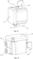
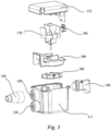
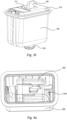
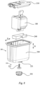
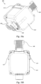
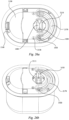
- the air pump 100 comprises a pump body 110, and the pump body 110 may include a first pump body 111 and a second pump body 112 ( Fig. 3 ) connected to each other.
- the first pump body 111 may include an air inlet 120 and an air outlet 130.
- a driving assembly is disposed in the pump body 110, as shown in Fig. 2 and Fig. 3 .
- the driving assembly may include an impeller 160 and a driving motor 170. During operation, an output shaft of the driving motor 170 drives the impeller 160 to rotate and produce air pressure, thereby generating air flow from the air inlet 120 to the air outlet 130.
- an output shaft of the driving motor 170 drives the impeller 160 to rotate and produce air pressure, thereby generating air flow from the air inlet 120 to the air outlet 130.
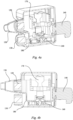
- a pump cover 180 may also be disposed in the pump body 110 for fixing and separating the impeller 160 and the driving motor 170 so that when the driving motor 170 drives the impeller 160 to rotate, the air flow can be directed from the air inlet 120 to the air outlet 130 via the pump cover 180 and the impeller 160, as depicted by the arrow in Fig. 2 .
- the pump cover 180 divides the inside of the pump body 110 into an air inlet cavity in communication with the air inlet 120, and an air outlet cavity in communication with the air outlet 130.
- the air pump 100 can deflate an inflation cell of the inflatable product, and when the connector 150 of the inflatable product is connected to the air outlet 130, the air pump can inflate the inflation cell of the inflatable product.
- the joint of the connector 150 of the inflatable product for connection to the air pump 100 may have a fixed size, the joint for connecting the inflatable product can have different sizes according to the size requirements of a connector of the inflatable product that is to be inflated and deflated.
- the air pump 100 comprises a knob switch 140 extending from the pump body 110.
- the knob switch 140 can be moved along the path to turn on/off a driving circuit to switch on/off the driving assembly, so that the air pump 100 is switched between a shutdown state (i.e., a stop state or neutral position) and a start state (i.e., an inflation position or deflation position).
- the driving assembly can also comprise a trigger switch 190, and the trigger switch 190 is electrically connected to the driving motor 170 to control switching the air pump 100 on and off.
- a start-up circuit of the driving motor 170 can be turned on to start the air pump 100, and when the knob switch 140 is moved to disengage from the trigger switch 190, the circuit is turned off to turn off the air pump 100.
- the knob switch 140 may be provided with an indicator 142 for indicating the state or position of the air pump, such as a water drop shape exemplarily shown in Fig. 1c , or a similar sign such as an arrow.
- an indicator 142 for indicating the state or position of the air pump, such as a water drop shape exemplarily shown in Fig. 1c , or a similar sign such as an arrow.
- inflation and deflation signs and a stop sign may be provided on the surface of the pump body 110.
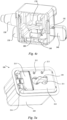
- Fig. 5a to Fig. 8 show an embodiment of the air pump 100 serving as a connected air pump.
- the connected air pump 100 comprises a shell 200 fixedly connected on a side wall of the inflatable product.
- the shell 200 includes an openable upper cover 210 and a bottom portion 220 that are detachably connected to form an internal chamber.
- the air pump 100 can be detachably received in the internal chamber and is easy to remove and insert according to present needs.
- the bottom portion 220 is provided with a vent hole 221, and an air valve 230 is mounted on the vent hole 221 to prevent air leakage.
- the air valve 230 may comprise a valve plug 231 and a valve cap 232, and the valve cap 232 may be provided with a plurality of slots to facilitate air circulation. In this way, after the air pump 200 is detachably inserted in the bottom portion 220 of the shell 200, the air pump 100 is moved such that the position of the air inlet 120 or air outlet 130 thereof matches the position of the air valve 230 of the shell 200 to inflate or deflate the inflatable product.
- the air pump 100 can be moved along a transverse direction, represented by arrow B in Fig. 8 , to connect the air outlet 130 or air inlet 120 to the air valve 230 of the shell 200, and optionally, the air pump 100 can be supported by a support component 240 ( Fig. 8 ).
- a support component 240 Fig. 8
- the air pump 100 can press against and move the support component 240 towards the air valve 230.
- the support component 240 can be reset to facilitate moving the air pump 100 away from the air valve 230.
- the upper cover 210 of the shell 200 is provided with an opening 211 through which the knob switch 140 of the air pump 100 passes such that it can be held by a user.
- the knob switch 140 when the knob switch 140 is moved towards the internal chamber of the shell 200 along the transverse direction, i.e., along the arrow B in Fig. 8 , the air pump 100 is also moved along the transverse direction, and the air inlet 120 or the air outlet 130 may be selectively aligned and connected with the air valve 230 of the shell 200.
- the opening 211 can be configured to limit knob switch 140 movement, such that the knob switch 140 can be rotated in the opening, and when the knob switch 140 has been moved and rotated into a desired position along the transverse direction, the knob switch 140 can be retained in place.
- a desired position e.g., an inflation state/position or a deflation state/position
- the air pump 100 can be switched on/off by rotating the knob switch 140.
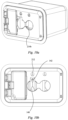
- the opening 211 may be bounded by at least a first segment 211a and a second segment 211b, as shown in Fig. 9a , at least one of the first segment 211a and the second segment 211b being associated with a limit structure to retain the knob switch 140 once it has been moved into a desired position along the transverse direction, i.e., retaining the air pump 100 in its inflation position or its deflation position.
- the first segment 211a may correspond to the first position or inflation state
- the second segment 211b may correspond to the second position or deflation state.
- the knob switch 140 when the knob switch 140 is located in a portion of the opening 211 bounded by the first segment 211a and moved along the transverse direction, it is moved into the first position, and when the knob switch 140 is located in a portion of the opening bounded by the second segment 211b and moved along the transverse direction, it is moved into the second position.
- the first segment 211a could alternatively correspond to the second position and the second segment 211b could alternatively correspond to the first position, depending on the location of the air inlet 120 and air outlet 130.
- the opening 211 may further be bounded by a third segment 211c, as shown in Fig. 9a , wherein the knob switch 140 is in the neutral position and unable to move in the transverse direction when it is at least partially located along the third segment 211c.
- the knob switch 140 may be prevented from rotation when it is located in the third segment 211c.
- the third segment 211c may correspond to a stop state/neutral position.
- the third segment 211c may be arranged between the first segment 211a and the second segment 211b or on one side of the first segment 211a or the second segment 211b as will be described below.
- the air pump 100 is also moved along the transverse direction towards the air valve 230 at the bottom of the shell 200, and due to the limit structure for the knob switch 140, the air inlet 120 or the air outlet 130 of the pump body 110 moves into communication with the air valve 230 and is retained there to perform one of the inflation or deflation operations.
- the air pump 100 becomes dislocated and moved towards the upper cover 210, away from the air valve 230 of the shell 200 to disconnect the air inlet 120 or the air outlet 130 from the air valve 230.
- the air pump 100 cannot be started by means of movement of the knob switch 140 in only the transverse direction.
- the air pump 100 can also not be started by mere rotation of the knob switch 140 without also moving along the transverse direction.
- the knob switch 140 is limited by virtue of the limit structure.
- the air pump 100 is synchronously moved along the transverse direction towards the bottom of the shell 200.
- the knob switch 140 is reversely rotated, it becomes dislocated and simultaneously moved along the transverse direction towards the upper cover 210 of the shell 200 to cause the pump body 110 to move towards the upper cover 210, thus stopping the driving motor 170. This helps to prevent unintended inflation or deflation caused by operation of the knob switch 140.
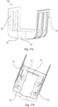
- the support component 240 is illustrated in Fig. 7a and Fig. 7b in accordance with one embodiment of the subject invention.
- the support component 240 is provided with notches 243, 244, 245 corresponding to the air inlet 120 and the air outlet 130 of the air pump 100 and the vent hole 221 of the bottom portion 220.
- the first notch 243 of the support component 240 corresponds to the vent hole 221.
- the air inlet 120 of the air pump 100 is located in the second notch 244 of the support component 240, and the air outlet 130 is located in the first notch 243, as shown in Fig. 10e .
- the air outlet 130 of the air pump 100 When in the deflation state, the air outlet 130 of the air pump 100 is located in the third notch 245 of the support component 240, and the air inlet 120 of the air pump corresponds to the first notch 243 of the support component 240, as shown in Fig. 11e .
- the support component 240 may include a base 241.
- the base 241 is provided with a plurality of bosses 246 located on the bottom around the vent hole 230, and each of the bosses 246 is sleeved with an elastic member 250 to cause the base 241 to automatically reset.
- components, such as elastic members 250 may be directly fixed to the bottom of the base 241 to assist in the reset function.
- the support component 240 may include a wall plate 242 that extends perpendicularly from a pair of opposing second edges of the base 241, and the pump body 110 of the air pump 100 can press the wall plate 242 of the support component 240 when the air pump 100 is moved along the transverse direction towards the air valve 230.
- the height of the wall plate 242 of the support component 240 may be greater than or equal to the length of the air inlet 120 and the length of the air outlet 130 that each protrude from the pump body 110.
- the wall plate 242 can abut against a bottom or a side of the pump body 110 according to different design requirements, so that the pump body 110 is reliably supported, and the internal structure of the shell 200 is more compact.
- the shell 200 of the connected air pump 100 may be provided with a space for accommodating a power line
- the upper cover 210 may include an openable take-up cover 215, as shown in Fig. 5a .
- the take-up cover 215 may also be provided with a notch 216, so that the take-up cover 215 can be closed after the power line is taken out or placed therein.
- the air pump 100 can be used independently as a hand-held air pump 100, and therefore, the connector 150 of the inflatable product can also be accommodated in the space to facilitate the use of the air pump when it is removed from the shell 200.
- the opening 211 of the upper cover 210 may be bounded by three segments, including a first segment 211a having an arched portion corresponding to the inflation state or position, a second segment 211b having an arched portion corresponding to the deflation state or position, and a third segment 211c having a straight portion corresponding to the stop state or neutral position.
- the third segment 211c may be located between the first segment 211a and the second segment 211b.
- the knob switch 140 is able to move between the first segment 211a and the second segment 211b along a path (arrow "A" in Fig.
- the knob switch 140 moves while located at the first segment 211a or the second segment 211b along the transverse direction.
- the knob switch 140 is unable to move along the transverse direction.
- the knob switch 140 be rotated counterclockwise to start the air pump 100.
- the indicator 142 of the knob switch 140 can point to the inflation sign 212 provided on the upper cover 210, thereby indicating that the air pump 100 is in an inflation state or position.
- the knob switch 140 when the knob switch 140 is moved from the third segment 211c to the second segment 211b along the path and then moved towards the inside of the internal chamber along the transverse direction, the knob switch 140 may be rotated counterclockwise to start the air pump 100.
- the indicator 142 of the knob switch 140 can point to the deflation sign 213 provided on the upper cover 210, thereby indicating that the air pump 100 is in a deflation state or position.
- the first segment 211a and the second segment 211b of the opening 211 are respectively provided with a vertical wall extending from an edge of the first and second segments 211a and 211b to the internal chamber of the shell 200.
- the limit structure comprises guide rails 214 disposed on the vertical walls, for example, a first guide rail 214a on the first segment 211a and a second guide rail 214b on the second segment 211b, as illustrated in Fig. 9b .
- the knob switch 140 of the air pump 100 is provided with protruding blocks 141 cooperating with the guide rails 211 or in an alternative embodiment (not shown) sliding grooves cooperating with flanges.
- the protruding blocks 141 may be symmetrically disposed on two sides of the knob switch 140.
- the guide rails 214a, 214b each extend obliquely from a starting end to a terminating end and towards the inside of the shell 200.
- the protruding blocks 141 of the knob switch 140 gradually move obliquely towards the inside of the shell 200 along the first guide rail 214a and/or the second guide rail 214b, thereby driving the pump body 110 downward within the shell 200.
- the downward movement of the pump body 110 is along the transverse direction B (as shown in Fig. 8 ), thus causing the air inlet 120 or the air outlet 130 to be aligned with the air valve 230 of the shell 200 to prevent unintended use or operation, as described above.
- the pump body 110 in the stop state or neutral position, may be substantially within the center of the shell 200, with the air inlet 120 and the air outlet 130 of the air pump 100 not aligned or in communication with the air valve 230, and with the valve plug 231 at the vent hole 221 closing the vent hole 221 to prevent air leakage.
- the neutral position can refer to other positions that are not the inflation position or deflation position.
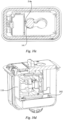
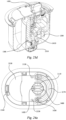
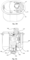
- the knob switch 140 When the knob switch 140 is moved from the third segment 211c to the first segment 211a and rotated counterclockwise, the protruding blocks 141 of the knob switch 140 are moved obliquely along the first guide rail 214a, pushing the connected air pump 100 to the inflation state or position, as shown in Fig. 10a to Fig. 10e .
- the indicator 142 of the knob switch 140 points to the inflation sign 212, as viewed from the outside of the shell 200.
- the pump body 110 presses downwardly against the vertical walls 242 of the support component 240, and the air outlet 130 of the air pump 120 is aligned with the air valve 230 and pushes the valve plug 231 to move down to open the vent hole 221.
- an inflation path is formed using the connected air pump 100. More particularly, air flow enters the shell 200 from the opening 211 of the upper cover 210, then enters the air inlet cavity of the pump body 110 from the air inlet 120 of the air pump 110, thereafter flowing into the air outlet cavity, and then entering the inflatable product via the air outlet 130 and the vent hole 221 in communication therewith to effect inflation.
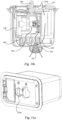
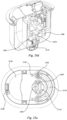
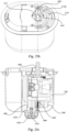
- the pump body 110 presses the vertical walls 242 of the support component 240 down, and the air inlet 120 of the air pump 100 is aligned with the air valve 230 and pushes the valve plug 231 to move down to open the vent hole 221.
- a deflation path is formed in the connected air pump 100. More particularly, the air flow enters the shell 200 from the inflatable product via the vent hole 221, then enters the air inlet cavity of the pump body 110 along the air inlet 120 of the air pump 100, thereafter flowing into the air outlet cavity, and then flowing out of the shell 200 from the opening 211 of the upper cover via the air outlet 130 to effect deflation.
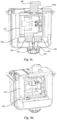
- Fig. 12a through Fig. 14b show a connected air pump 100 according to a second embodiment of the present invention, which differs from the above embodiment in the arrangement of the opening 411 of the shell 200 and the knob switch 340 of the air pump.
- the stop state or neutral position of the connected air pump 100 is shown.
- the first segment 411a and the second segment 411b of the opening 411 of the upper cover 410 also have arched segments for rotation of the knob switch 340, and the third segment 411c is disposed on one side of the first segment 411a or the second segment 411b.
- the first segment 411a may correspond to the first position
- the second segment 411b may correspond to the second position.
- the knob switch 340 when the knob switch 340 is located in a portion of the opening bounded by the first segment 411a and moved along the transverse direction, it is moved into the first position.
- the knob switch 340 When the knob switch 340 is located in a portion of the opening bounded by the second segment 411b and moved along the transverse direction, it is moved into the second position.
- the first segment 411a could alternatively correspond to the second position and the second segment 411b could alternatively correspond to the first position depending on the location of the air inlet 120 and air outlet 130.
- the limit structure comprises limit plates 412 respectively extending from the edges of the first segment 411a and the second segment 411b along a path.
- the knob switch 340 of the air pump 100 is provided with clamping grooves 341. After the knob switch 340 is moved along the path to the first segment 411a or the second segment 411b, the knob switch 340 may be pressed to move along the transverse direction towards the internal chamber of the shell 200 and rotated. As the knob switch 340 is pressed, the clamping grooves 341 cooperate with the limit plates 412 to fix the knob switch 340 into its desired rotation and transverse position.
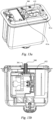
- the air pump 100 is at an edge of the shell 200, and thus, neither the air inlet 120, nor the air outlet 130 of the air pump 100 is aligned or in communication with the air valve 230, as shown in Fig. 12b , and at this time, the valve plug 231 at the vent hole blocks the vent hole 232.
- the knob switch 340 When the knob switch 340 is translated from the third segment 411c to the first segment 411a along the path and then moved towards the internal chamber along the transverse direction, the knob switch 340 is rotated counterclockwise, and the clamping grooves 341 of the knob switch 340 are engaged with the limit plates 412. As such, the connected air pump 100 is moved into the inflation state, as shown in Fig. 13a and Fig. 13b . Similarly, when the knob switch 340 is translated from the third segment 411c to the second segment 411b along the path and then moved towards the internal chamber along the transverse direction, the knob switch 340 is rotated counterclockwise, and the clamping grooves 341 of the knob switch 340 are engaged with the limit plates 412. As such, the connected air pump 100 is moved into a deflation state, as shown in Fig. 14a and Fig. 14b .
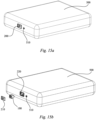
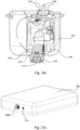
- Fig. 15a and Fig. 15b show an embodiment of the present invention applying the connected air pump 100 to an inflatable product, such as a mattress 500.
- the air pump 100 can be taken out by removing the upper cover 210 of the shell 200 from the bottom portion 220, so that the air pump 100 can be used independently from the shell 200 to inflate and deflate other inflatable products, and later reintroduced into the shell 200.
- the mattress 500 may be separately inflated and deflated through the air valve 510. Therefore, the present invention provides flexible and variable use whether the air pump 100 is used alone or in combination with the shell 200 as a connected air pump.
- Fig. 16a and Fig. 16b show an air pump 600 for an inflatable product.
- the air pump 600 includes a pump body 610, an air inlet 620 and an air outlet 630.
- a drive assembly is arranged in the pump body 610, and a knob switch 640 extends outside of the pump body 610.
- a portion of the outer side wall of the pump body 610 may be enclosed by the support component 740 and provided with an abutting part cooperating with the support component 740.
- the abutting part may be shaped as a pair of convex strips 613 protruding from the outer side wall of the pump body 610 and arranged on opposing sides.
- the pair of convex strips 613 may advantageously extend along a direction parallel to a side wall of the inflatable product. Accordingly, as shown in Fig. 17a and Fig.
- the support component 740 may comprise a base 741, and the base 741 may include a notch 745 having a location corresponding to the air valve 230 of the shell for aligning the air inlet 620 and/or the air outlet 630 of the air pump 600 with the air valve 230 of the shell.
- One side of an edge of the base 741 that faces the pump body 610 is provided with a pair of support plates 743 which extend perpendicularly and are oppositely arranged on a pair of first opposing edges of the base 741
- the pair of support plates 743 may respectively extend to enclose most of the outer side wall of the pump body 610 and can abut against the pair of convex strips 613 of the pump body 610. In this way, as shown in Fig.
- the convex strip 613 on the pump body 610 can press the support plate 743 of the support component 740 to move towards the air valve 230. Otherwise, when the pump body 610 translates away from the air valve 230 along the transverse direction, the support component 740 can be reset and the pump body 610 be caused to move away from the air valve 230 by the abutting action of the support plate 743 and the convex strip 613. At the same time, since the support component 740 encloses part of the pump body 610, more stable support can be provided to the pump body 610.
- the convex strips 613 extends along a direction parallel to the side wall, they abut against a free end of the support plate 743 to further provide a support function to smooth movement of the pump body 610 when the air pump 600 translates along the path such that the position of the air inlet 620 or the air outlet 630 matches (or at least partially overlaps) the position of the air valve 230 and connects thereto.
- the support plate 743 may be provided with a grid 744.
- the grid 744 may extend parallel or perpendicular to a side wall of the inflatable product.
- the support component 740 may further include a pair of wall plates 742 extending perpendicularly from the edge of the base 741 towards the pump body and arranged oppositely.
- the pair of wall plates 742 are arranged alternately with the pair of support plates 743, as shown in Fig. 17b .
- the length of the wall plates 742 may be greater than or equal to the length of the part of the pump body 610 that surrounds the air inlet 620 and the air outlet 630 and protrude outwardly along the transverse direction. As shown in Fig. 19 , the wall plates 742 can abut against the bottom or side of the pump body 610.
- one of the pair of wall plates 742 may abut against a bottom wall of the pump body 610 that faces the air valve 230, thereby ensuring reliable support for the pump body 610 and making the internal structure of the shell 820 more compact.
- a plurality of fixing holes 746 are provided in the base 741 of the support component 740, as shown in Fig. 17b . Accordingly, as shown in Fig. 18 and Fig. 19 , a plurality of bosses 752 may be provided in the internal chamber of the shell 820. Each boss 752 is sleeved with an elastic member 753 and is mated with a fixing hole 746 of the support component 740.
- the bosses 752 may be provided with a thread so as to fixedly connect the bosses 752 by passing, for example, a threaded fastener 751 through the fixing hole 746, thereby realizing an automatic reset function by the directional bias of the elastic member 753.
- similar bosses may also be provided at the bottom of the base 741 of the support component 740 facing the air valve 230 of the shell 820, as in the support component 240 described above.
- Fig. 20a to Fig. 20f show another embodiment of an air pump 1000 for an inflatable product.
- the air pump 1000 comprises a pump body 1100.
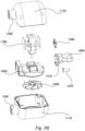
- the pump body 1100 may comprise a first pump body 1110 and a second pump body 1120 ( Fig. 20f ) connected to each other.
- a driving assembly is located inside the pump body 1100 and comprises an impeller 1600, a driving motor 1700, and a pump cover 1800.
- the pump cover 1800 fixes and separates the impeller 1600 and the driving motor 1700.
- a knob switch 1400 extends outside of the pump body 1100.
- the knob switch 1400 may be provided with an indicator 1420 for indicating the state or position of the air pump 1000, and a protruding block 1410 cooperating with the opening 2110 of the shell 2000 when the air pump 1000 is used as a connected air pump.
- the trigger switch 1900 in the pump body 1100 can be engaged/disengaged to turn on/off a start-up circuit of the driving motor 1700, thereby switching on/off the air pump 1000.
- air can flow from the air inlet 1200 to the air outlet 1300 via the pump cover 1800 and the impeller 1600 along the arrow in Fig. 20e .
- an air outlet 1300 may be provided on the first pump body 1110
- an air inlet 1200 may be provided on the second pump body 1120
- a switching lever 1430 may be disposed on the same plane of the knob switch 1400, as shown in Fig. 20a .
- the air pump 1000 can be switched between a first position, a second position, and any intermediate or neutral positions by means of the movement of the switching lever 1430, which will be described in detail below.
- Fig. 21 and Fig. 22 show an embodiment of the air pump 1000 connected to the shell 2000.
- an upper cover 2100 and a bottom portion 2200 of the shell 2000 are detachably connected to form an internal chamber.
- the bottom portion 2200 is provided with a vent hole 2210, and an air valve 2300 is mounted on the vent hole 2210.
- the air valve 2300 may comprise a valve plug 2310 and a valve cap 2320.
- the air pump 1000 is detachably arranged within the bottom portion 2200 of the shell 2000 and supported by a support component 2400.
- the knob switch 1400 of the air pump 1000 extends through an opening of the upper cover 2100 and out of the shell 2000.
- the switching lever 1430 of the air pump 1000 also extends through the opening 2170 of the upper cover 2100 and out of the shell 2000.
- the opening 2110, 2170 of the upper cover 2100 may comprise two segments: a first segment 2110 provided for the knob switch 1400 of the air pump 1000 to extend through, and a second segment 2170 provided for the switching lever 1430 to extend through.
- the first segment 2110 may be provided with a limit structure to limit the knob switch 1400, and the second segment 2170 provides a movement path for the switching lever 1430 such that the air pump is switched between the first position and the second position.
- the first pump body 1110 and the second pump body 1120 ( Fig. 20f ) are fixed integrally with the air inlet 1200 and the air outlet 1300.
- the pump body can be fixedly arranged on the shell or the bottom portion, and the air inlet and the air outlet are arranged on a circular flat plate which is rotatably connected to the pump body and fixedly connected to the knob switch.
- the user may then rotate the knob switch to correspondingly connect the air inlet or the air outlet to the vent hole depending on the direction of rotation.
- the impeller forms a partially sealed passage with the air inlet and the air outlet.
- the bottom of the shell or the bottom portion is partially planar.
- the vent hole is not provided with an air valve, but is simply provided as a port bounded by a flat portion of the shell, and the air inlet and the air outlet do not extend outwardly, and are arranged along the same plane with the bottom of the air pump.
- the shapes of the air inlet and the air outlet match the vent hole, and the air inlet and the air outlet 1300 are respectively connected to the vent hole in a corresponding way through rotation, so as to achieve the purposes of inflation and deflation.
- the non-air inlet/outlet position at the bottom of the air pump blocks the vent hole by rotation to form a seal.
- the bottom of the shell or the base can be arranged to be non-planar, so that the air inlet and the air outlet can form a gap with the bottom portion when not aligned with the vent hole, thus allowing the air flow to flow smoothly.
- the bottom of the pump body is fixedly arranged with the pump body, such that it cannot independently move.
- the bottom of the pump body may be non-planar and include a vent port.
- the air inlet and the air outlet are arranged on a circular flat plate inside of the air pump and are kept in fluid communication with the impeller, and the flat plate is connected to the pump body in a rotating manner and is in contact with the bottom of the pump body.
- Vent grids are in fluid communication with one of the air inlet and the air outlet.
- the air inlet and the air outlet are also not provided with convex shapes (they do not protrude outwardly from the pump body), but are arranged on a same or similar plane.
- the shapes of the air inlet and the air outlet match the vent port at the bottom of the pump body, and are respectively connected to the vent port at the bottom of the pump body through the rotation of the flat plate, and the vent port and the ventilation grids respectively become external air inlet/outlet ports of the air pump.
- the user enables the air inlet and the air outlet to rotate along with the flat plate inside the pump body by rotating the knob switch, such that the air inlet and the air outlet are respectively connected to the vent port, thus achieving the purpose of switching internal air passages.
- the air flow enters the air inlet through the ventilation grids, and reaches the vent port from the air outlet after being pressurized by the impeller, thus realizing the inflation function.
- the air inlet and the vent port are correspondingly connected, the air flow enters the air inlet through the vent port, and reaches the ventilation grids from the air outlet after being pressurized by the impeller, so as to be pumped out of the inflatable product.
- the shell can be designed as an open fixed seat, the purpose of which is only to install the pump body on the inflatable product.
- the upper cover may be provided with an openable take-up cover, and a notch for a power line to stretch out when the take-up cover is closed.
- the support component 2400 comprises a pivot cylinder 2410 received in the internal chamber of the shell 2000 and provided with an elastic member 2440. Accordingly, a support pillar 2430 cooperating with the pivot cylinder 2410 is disposed in the internal chamber of the shell 2000, that is, on the bottom portion 2200.
- the support component 2400 is shown to include the pivot cylinder 2410 in which an elastic member 2440 is received.
- One end of the elastic member 2440 may be sleeved on a positioning post 2220 formed on the bottom portion 2200, as shown in Fig.
- the support component 2400 may further comprise fixing portions 2420 symmetrically disposed on side walls of the pivot cylinder 2410. Accordingly, support pillars 2230 cooperating with the fixing portions 2420 are disposed on the bottom portion 2200 of the shell 2000.
- the support component 2400 can effectively support the pump body 1100 of the air pump 1000, and when the pump body 1100 is moved up, the support pillar 2430 automatically resets to maintain the abutment against the pump body 1100.
- the side walls of the bottom portion 2200 of the shell 2000 can be configured to tilt gradually towards the internal chamber from the upper cover to the bottom, i.e., the walls are slightly tapered. In this way, after the pump body 1100 of the air pump 1000 is placed into the internal chamber of the shell 2000, the side walls of the shell 2000 play a certain role in positioning the pump body but do not clamp the pump body 1100.
- Fig. 23a to Fig. 23d show the connected air pump in a stop state adjacent to the inflation position.
- the switching lever 1430 of the air pump is located near the inflation sign 2120, and the indicator 1420 of the knob switch 1400 points to the right side.
- the first segment 2110 on the upper cover of the shell 2000 has an arched segment for the knob switch 1400 to rotate therein along the path.
- the second segment 2170 is configured in a generally semicircular form and surrounds the first segment 2110 for the switching lever 1430 to move from a position near the inflation sign 2120 to a position near the deflation sign 2130, such that the pump body is switched from the first position to the second position.
- the pump body 1100 of the air pump does not press the support pillar 2430 of the pivot, and the air outlet 1300 is aligned but spaced from the vent hole 2210 such that it is not yet in communication with the air valve 2310.
- Fig. 24a to Fig. 24d show the connected air pump in a stop state adjacent to the deflation position.
- the switching lever 1430 of the air pump is rotated along the second segment 2170 to the position near the deflation sign 2130, thereby driving the pump body 1100 to rotate within the internal chamber of the shell 2000.
- the indicator 1420 of the knob switch 1400 points to the left side.
- the pump body 1100 of the air pump does not press the support pillar 2430 of the pivot, and the air inlet 1200 is aligned with but spaced from the vent hole 2210 such that it is not yet in communication with the air valve 2310.
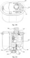
- Fig. 25a to Fig. 25e show the connected air pump in an inflation state or inflation position. It can be seen from Fig. 25a that the switching lever 1430 of the air pump 1000 is still located near the inflation sign 2120, while the knob switch 1400 is rotated counterclockwise until the indicator 1420 generally points in the direction of the inflation sign 2120. In order to start the air pump 1000, during the switching of the knob switch 1400 from the stop state to the start state, the knob switch 1400 is first pressed towards the inside of the shell 2000 before rotation. As best shown in Fig.
- the edge of the first segment 2110 is extended towards the internal chamber along the transverse direction to form a vertical wall 2110a, and the limit structure comprises a stop flange 2111 extending out from the vertical wall 2110a along the path.
- the stop flange 2111 can restrict the knob switch 1400 in the transverse direction after it has been rotated into position.
- the protruding block 1410 on the knob switch 1400 is engaged with and retained by the stop flange 2111.
- the pump body 1100 in response presses the support pillar 2430 of the pivot mechanism, thereby pressing the elastic member 2440 downwardly in the transverse direction.
- the air outlet 1300 moves towards the vent hole 2210 and push the valve plug 2310 to move down to open the vent hole 2210.
- an inflation path is formed in the connected air pump 1000.
- the air flow enters the shell 2000 from the first segment 2110 or the second segment 2170 of the upper cover 2100 and then enters the air inlet cavity of the pump body 1100 along the air inlet 1200 of the air pump 1000, whereafter it flows into the air outlet cavity, and then enters the inflatable product 500 via the air outlet 1300 and finally the vent hole 2210 to effect inflation.
- the elastic member 2440 is released from the restriction of the protruding block 1410 by stop flange 2111 and becomes elastically reset, resulting in the support pillar 2430 and the pump body 1110 being ejected towards the outside of the shell 2000 along the transverse direction, thereby restoring to the stop state shown in 23a.
- Fig. 26a to Fig. 26e show the connected air pump in the deflation state or the deflation position. It can be seen from Fig. 26a that the switching lever 1430 of the air pump 1000 is still located near the deflation sign 2130, while the knob switch 1400 is rotated counterclockwise until the indicator 1420 generally points in the direction of the deflation sign 2130. As such, when the air pump 1000 is started, the knob switch 1400 is pressed down towards the inside of the shell 2000, then rotated along the first segment 2110, and retained by the stop flange 2111, so that the air pump 1000 is in a deflation state.
- the pump body 1100 of the air pump 1000 presses the support pillar 2430 of the pivot, thereby pressing the elastic member 2440.
- the air inlet 1200 is moved towards the vent hole 2210 and pushes the valve plug 2310 to move down to open the vent hole 2210.
- a deflation path is formed in the connected air pump 1000.
- the air flow enters the shell 2000 from the inflatable product 500 via the vent hole 2210, enters the air inlet cavity of the pump body 1100 along the air inlet 1200 of the air pump 1000, flows into the air outlet cavity, and then flows out of the shell 2000 from the first segment 21 10/the second segment 2170 of the upper cover 2100 to effect deflation.
- Figs. 27a and Fig. 27b show the air pump 1000 connected to an inflatable product such as a mattress 500. Similar to Fig. 15a and Fig. 15b , the air pump 1000 in the connected air pump 1000 can be detached from the bottom portion 2200 and taken out to independently serve the inflation or deflation functionality.
- the air pump can be switched between inflation and deflation by means of mechanized operation of the knob switch.
- This arrangement simplifies the operation and the internal structure of the air pump because it does not require a traditional air passage switching device, thus also saving on the production costs.
- the air pump may be used even when it is detached from the shell.
- the inflatable product can be quickly and effectively inflated and deflated by the structural cooperation between the knob switch of the air pump and the opening of the upper cover of the shell, so that the user experience is further simplified and improved.
- the present invention can be used as a connected air pump or detached, external air pump according to different needs, thus being more widely applicable to various inflatable products, and having significant cost effectiveness and replaceability.
- the phrase "at least one of” preceding a series of items, with the terms “and” or “or” to separate any of the items, modifies the list as a whole, rather than each article of the list (i.e., each item).
- the phrase "at least one of” includes at least one of any one of the items, and/or at least one of any combination of the items, and/or at least one of each of the items.
- the phrases “at least one of A, B, and C" or “at least one of A, B, or C” each refer to only A, only B, or only C.
Landscapes
- Engineering & Computer Science (AREA)
- Mechanical Engineering (AREA)
- General Engineering & Computer Science (AREA)
- Physics & Mathematics (AREA)
- Fluid Mechanics (AREA)
- Chemical & Material Sciences (AREA)
- Combustion & Propulsion (AREA)
- Ocean & Marine Engineering (AREA)
- Compressors, Vaccum Pumps And Other Relevant Systems (AREA)
- Massaging Devices (AREA)
Claims (9)
- Aufblasbares Produkt, umfassend: eine Seitenwand, die eine Aufblaszelle definiert; ein Gehäuse (200), das sich auf der Seitenwand befindet und in die Aufblaszelle erstreckt, wobei das Gehäuse (200) eine innere Kammer und ein Luftventil (230) definiert, wobei sich das Luftventil (230) in einer Fluidverbindung mit der inneren Kammer und der Aufblaszelle befindet; und eine Luftpumpe (100), die einen Lufteinlass (120) und einen Luftauslass (130) umfasst, wobei sich die Luftpumpe (100) zumindest teilweise innerhalb der inneren Kammer befindet;
wobeidie Luftpumpe (100) innerhalb der inneren Kammer zwischen einer ersten Position, einer zweiten Position und einer neutralen Position bewegbar ist;wenn sich die Luftpumpe (100) in der ersten Position befindet, der Lufteinlass (120) mit dem Luftventil (230) verbunden ist;wenn sich die Luftpumpe (100) in der zweiten Position befindet, der Luftauslass (130) mit dem Luftventil (230) verbunden ist; undwenn sich die Luftpumpe (100) in der neutralen Position befindet, weder der Lufteinlass (120) noch der Luftauslass (130) mit dem Luftventil (230) verbunden ist,wobei das Gehäuse (200) eine obere Abdeckung (210) umfasst, die eine Öffnung (211) definiert, und die Luftpumpe (100) einen Knopfschalter (140) umfasst, der sich durch die Öffnung (211) erstreckt,und wobei die Luftpumpe (100) ferner umfasst:einen Pumpenkörper (110); undeine Antriebsanordnung, die sich in dem Pumpenkörper (110) befindet;wobei sich der Knopfschalter (140) von dem Pumpenkörper (110) erstreckt und in der Öffnung (211) entlang eines Wegs bewegbar ist, wodurch bewirkt wird, dass sich der Pumpenkörper (110) ebenfalls entlang des Wegs bewegt; undwobei der Knopfschalter (140) und der Pumpenkörper (110) entlang einer Querrichtung bewegbar sind, die quer zu dem Weg verläuft, um in Abhängigkeit von der Positionierung des Knopfschalters (140) und des Pumpenkörpers (110) entlang des Wegs selektiv den Luftauslass (130) mit dem Luftventil (230) in der ersten Position zu verbinden oder den Lufteinlass (120) mit dem Luftventil (230) in der zweiten Position zu verbinden,dadurch gekennzeichnet, dassdie Öffnung (211) durch mindestens ein erstes Segment (211a) und ein zweites Segment (211b) begrenzt wird, wobei der Knopfschalter (140) entlang des Wegs zwischen dem ersten Segment (211a) und dem zweiten Segment (211b) bewegbar ist;wobei das Gehäuse (200) ferner eine Begrenzungsstruktur umfasst, um den Knopfschalter (140) und den Pumpenkörper (110) in der ersten Position oder der zweiten Position zu halten und eine Bewegung des Knopfschalters (140) und des Pumpenkörpers (110) entlang der Querrichtung zu verhindern;wobei, wenn der Knopfschalter (140) mit der Begrenzungsstruktur gekoppelt ist, die Begrenzungsstruktur den Knopfschalter (140) und den Pumpenkörper (110) in einer von der ersten Position oder der zweiten Position hält. - Aufblasbares Produkt nach Anspruch 1, ferner umfassend eine senkrechte Wand, die sich von einem Rand des ersten Segments (211a) und einem Rand des zweiten Segments (211b) in die innere Kammer erstreckt;wobei die Begrenzungsstruktur eine erste Führungsschiene (214a), die sich auf der senkrechten Wand angrenzend an das erste Segment (211a) befindet und schräg von einem Anfangsende zu einem Abschlussende zum Inneren des Gehäuses (200) hin erstreckt, und eine zweite Führungsschiene (214b) umfasst, die sich auf der senkrechten Wand angrenzend an das zweite Segment (211b) befindet und schräg von einem Anfangsende zu einem Abschlussende zum Inneren des Gehäuses (200) hin erstreckt;wobei der Knopfschalter (140) einen vorstehenden Block (141) umfasst, der mit einer von der ersten Führungsschiene (214a) und der zweiten Führungsschiene (214b) während der Drehung des Knopfschalters (140) zusammenwirkt, um den Knopfschalter (140) und den Pumpenkörper (110) weiter entlang der Querrichtung in einer von der ersten Position oder der zweiten Position zu halten.
- Aufblasbares Produkt nach Anspruch 1, wobei die Begrenzungsstruktur eine Begrenzungsplatte (412) umfasst, die sich entlang des ersten Segments (211a) und des zweiten Segments (211b) erstreckt, und der Knopfschalter (140) mit einer Klemmnut (341) versehen ist, die mit der Begrenzungsplatte (412) zusammenwirkt, um den Knopfschalter (140) und den Pumpenkörper (110) in entweder der ersten Position oder der zweiten Position zu halten.
- Aufblasbares Produkt nach Anspruch 1, wobei die Öffnung (211) in der Abdeckung (180) durch ein erstes Segment (211a) und ein zweites Segment (211b) begrenzt wird und sich eine senkrechte Wand von einem Rand des ersten Segments (211a) in die innere Kammer erstreckt, wobei sich eine Begrenzungsstruktur auf der senkrechten Wand befindet und einen Anschlagflansch (2111) umfasst, und wobei der Knopfschalter (140) einen vorstehenden Block (141) umfasst, der mit dem Anschlagflansch (2111) zusammenwirkt, um den Knopfschalter (140) und den Pumpenkörper (110) in entweder der ersten Position oder der zweiten Position zu halten.
- Aufblasbares Produkt nach Anspruch 1, wobei die Öffnung (211) durch mindestens ein erstes Segment (211a) und ein zweites Segment (211b) begrenzt wird, wobei das zweite Segment (211b) eine Bogenform definiert, und wobei der Pumpenkörper (110) ferner einen Schalthebel (1430) umfasst, der sich durch eine Bereich der Öffnung (211) erstreckt, der durch das zweite Segment (211b) begrenzt wird, und wobei der Schalthebel (1430) entlang des zweiten Segments (211b) bewegt wird, um entweder den Lufteinlass (120) oder den Luftauslass (130) mit dem Luftventil (230) auszurichten.
- Aufblasbares Produkt nach Anspruch 1, ferner umfassend ein Stützbauteil (240), das sich in der inneren Kammer des Gehäuses (200) befindet und die Luftpumpe (100) in der Querrichtung abstützt, wobei, wenn die Luftpumpe (100) entlang der Querrichtung zum Luftventil (230) hin bewegt wird, der Pumpenkörper (110) derart auf das Stützbauteil (240) drückt, dass es sich zum Luftventil (230) hin bewegt, und wobei, wenn die Luftpumpe (100) entlang der Querrichtung von dem Luftventil (230) weg bewegt wird, das Stützbauteil (240) die Luftpumpe (100) derart beaufschlagt, dass sie sich von dem Luftventil (230) weg bewegt.
- Aufblasbares Produkt nach Anspruch 6, wobei das Stützbauteil (240) eine Basis umfasst, die mindestens einen von dem Lufteinlass und dem Luftauslass abstützt, wobei die Basis (241) mindestens eine Einbuchtung (216), die dem Luftventil (230) des Gehäuses (200) entspricht, und eine Vielzahl von Auswölbungen (246) definiert, die sich gegenüber der Luftpumpe (100) befinden, wobei jede Auswölbung (246) der Vielzahl von Auswölbungen (246) ein darum gehülltes elastisches Element (250) umfasst und wobei das Stützbauteil (240) ferner eine Wandplatte (242) umfasst, die sich perpendikular von einem Rand der Basis (241) erstreckt.
- Aufblasbares Produkt nach Anspruch 6, wobei das Stützbauteil (240) einen Drehzapfen umfasst, der mit einem elastischen Element (2440) versehen ist, wobei der Drehzapfen den Pumpenkörper in der inneren Kammer stützt und wobei das Gehäuse (200) eine Stützsäule (2430) umfasst, die drehbar mit dem Drehzapfen verbunden ist.
- Aufblasbares Produkt nach Anspruch 6, wobei das Stützbauteil (240) eine Basis (741) umfasst, die sich zwischen einem Paar von ersten entgegengesetzten Rändern der Basis (741) erstreckt und mindestens einen von dem Lufteinlass (120) und dem Luftauslass (130) stützt, wobei die Basis (741) mindestens eine Einbuchtung (745) definiert, die dem Luftventil (230) entspricht, wobei sich eine Stützplatte (743) von jedem Rand des Paares von ersten entgegengesetzten Rändern erstreckt und wobei sich die Stützplatten (743) entlang des Pumpenkörpers (110) zum Knopfschalter (140) hin erstrecken.
Priority Applications (2)
| Application Number | Priority Date | Filing Date | Title |
|---|---|---|---|
| EP24185887.7A EP4414560B1 (de) | 2019-06-21 | 2020-06-16 | Luftpumpe für ein aufblasbares produkt und aufblasbares produkt mit eingebauter luftpumpe |
| EP25211071.3A EP4660456A1 (de) | 2019-06-21 | 2020-06-16 | Luftpumpe für ein aufblasbares produkt und aufblasbares produkt mit eingebauter luftpumpe |
Applications Claiming Priority (3)
| Application Number | Priority Date | Filing Date | Title |
|---|---|---|---|
| CN201920946721 | 2019-06-21 | ||
| CN201921277471 | 2019-08-06 | ||
| CN202020321256.3U CN212155088U8 (zh) | 2019-06-21 | 2020-03-16 | 充气产品 |
Related Child Applications (3)
| Application Number | Title | Priority Date | Filing Date |
|---|---|---|---|
| EP24185887.7A Division EP4414560B1 (de) | 2019-06-21 | 2020-06-16 | Luftpumpe für ein aufblasbares produkt und aufblasbares produkt mit eingebauter luftpumpe |
| EP24185887.7A Division-Into EP4414560B1 (de) | 2019-06-21 | 2020-06-16 | Luftpumpe für ein aufblasbares produkt und aufblasbares produkt mit eingebauter luftpumpe |
| EP25211071.3A Division EP4660456A1 (de) | 2019-06-21 | 2020-06-16 | Luftpumpe für ein aufblasbares produkt und aufblasbares produkt mit eingebauter luftpumpe |
Publications (2)
| Publication Number | Publication Date |
|---|---|
| EP3754192A1 EP3754192A1 (de) | 2020-12-23 |
| EP3754192B1 true EP3754192B1 (de) | 2024-08-07 |
Family
ID=71103285
Family Applications (3)
| Application Number | Title | Priority Date | Filing Date |
|---|---|---|---|
| EP24185887.7A Active EP4414560B1 (de) | 2019-06-21 | 2020-06-16 | Luftpumpe für ein aufblasbares produkt und aufblasbares produkt mit eingebauter luftpumpe |
| EP25211071.3A Pending EP4660456A1 (de) | 2019-06-21 | 2020-06-16 | Luftpumpe für ein aufblasbares produkt und aufblasbares produkt mit eingebauter luftpumpe |
| EP20180228.7A Active EP3754192B1 (de) | 2019-06-21 | 2020-06-16 | Luftpumpe für ein aufblasbares produkt und aufblasbares produkt mit eingebauter luftpumpe |
Family Applications Before (2)
| Application Number | Title | Priority Date | Filing Date |
|---|---|---|---|
| EP24185887.7A Active EP4414560B1 (de) | 2019-06-21 | 2020-06-16 | Luftpumpe für ein aufblasbares produkt und aufblasbares produkt mit eingebauter luftpumpe |
| EP25211071.3A Pending EP4660456A1 (de) | 2019-06-21 | 2020-06-16 | Luftpumpe für ein aufblasbares produkt und aufblasbares produkt mit eingebauter luftpumpe |
Country Status (2)
| Country | Link |
|---|---|
| US (2) | US11892001B2 (de) |
| EP (3) | EP4414560B1 (de) |
Families Citing this family (2)
| Publication number | Priority date | Publication date | Assignee | Title |
|---|---|---|---|---|
| EP3994357A4 (de) | 2019-07-05 | 2023-06-07 | Intex Industries Xiamen Co. Ltd | Diversifizierte und abnehmbare pumpsysteme sowie verfahren zum aufblasen und entleeren von aufblasbaren gegenständen |
| CN218177492U (zh) | 2022-03-23 | 2022-12-30 | 上海荣威塑胶工业有限公司 | 内置电动气泵 |
Family Cites Families (11)
| Publication number | Priority date | Publication date | Assignee | Title |
|---|---|---|---|---|
| US6990700B2 (en) * | 2001-06-22 | 2006-01-31 | Team Worldwide Corporation | Inflatable product provided with electric air pump |
| US20050079077A1 (en) * | 2003-06-09 | 2005-04-14 | Tsai Jing Hong | Reversible inflation system |
| US20060053561A1 (en) * | 2004-09-13 | 2006-03-16 | The Coleman Company, Inc. | Airbed with built-in air pump |
| CN2743582Y (zh) * | 2004-09-30 | 2005-11-30 | 巫新财 | 输气装置 |
| US7210902B2 (en) * | 2004-10-05 | 2007-05-01 | Rong-Jyh Song | Two-way air pump |
| US7128525B2 (en) * | 2004-12-29 | 2006-10-31 | Ho Lee Co., Ltd. | Air pump |
| US8210834B2 (en) * | 2009-07-23 | 2012-07-03 | Dongguan Tiger Point, Metal & Plastic Products Co., Ltd. | Air pump for inflatable article |
| CN201606284U (zh) * | 2010-01-26 | 2010-10-13 | 宋荣治 | 吸吹两用泵浦 |
| US20150316067A1 (en) * | 2014-05-05 | 2015-11-05 | Dongguan Tiger Point, Metal & Plastic Products Co., Ltd. | Rotary adjustment controller of an air pump |
| EP4471275B1 (de) * | 2015-10-16 | 2026-08-19 | Intex Marketing Ltd. | Multifunktionsluftpumpe |
| US10273966B2 (en) * | 2016-03-02 | 2019-04-30 | Sun Pleasure Company Limited | Built-in air pump |
-
2020
- 2020-06-16 EP EP24185887.7A patent/EP4414560B1/de active Active
- 2020-06-16 EP EP25211071.3A patent/EP4660456A1/de active Pending
- 2020-06-16 EP EP20180228.7A patent/EP3754192B1/de active Active
-
2023
- 2023-02-28 US US18/115,266 patent/US11892001B2/en active Active
- 2023-10-06 US US18/377,557 patent/US12221969B2/en active Active
Also Published As
| Publication number | Publication date |
|---|---|
| EP4414560A3 (de) | 2024-10-16 |
| EP3754192A1 (de) | 2020-12-23 |
| US12221969B2 (en) | 2025-02-11 |
| US11892001B2 (en) | 2024-02-06 |
| EP4414560B1 (de) | 2025-12-03 |
| EP4414560A2 (de) | 2024-08-14 |
| EP4660456A1 (de) | 2025-12-10 |
| US20240035481A1 (en) | 2024-02-01 |
| US20230204039A1 (en) | 2023-06-29 |
Similar Documents
| Publication | Publication Date | Title |
|---|---|---|
| US11680573B2 (en) | Air pump for an inflatable product and an inflatable product with a built-in air pump | |
| US12221969B2 (en) | Air pump for an inflatable product and an inflatable product with a built-in air pump | |
| EP3059451B1 (de) | Eingebaute elektrische aufblaspumpe | |
| US9033678B2 (en) | Air pump having an auto-stop control device | |
| US7020921B2 (en) | Inflating/deflating device in combination with an inflatable mattress having multiple chambers | |
| US8480375B2 (en) | Auto-stop air pump | |
| CN108317097B (zh) | 充气泵 | |
| US11339792B2 (en) | Air pump with automatic stop of inflation and deflation | |
| US8235684B2 (en) | Air pump capable of inflating and deflating an inflatable product | |
| US11460043B2 (en) | Internal and external dual-purpose air pump, inflatable product and lifting handle device | |
| US20160123349A1 (en) | Electric Air Pump for Inflatable Body | |
| CN210660669U (zh) | 充放气气泵 | |
| EP3674560A1 (de) | Luftpumpe für einen aufblasbaren körper | |
| JP7554811B2 (ja) | 膨張可能物体を膨張及び収縮するための多様化され取外し可能なポンプシステム及び方法 | |
| US11988216B2 (en) | Built-in air pump with rapid inflation and deflation | |
| CN211623775U (zh) | 可拆卸内置气泵及充气产品 | |
| CN111852921B (zh) | 电动气泵的换气结构 | |
| CN212454905U (zh) | 电动气泵的换气结构 | |
| CN208185017U (zh) | 用于充气体的内置气泵 | |
| CN108131308B (zh) | 一种多气室电动充气气泵 | |
| CN202579221U (zh) | 一种气泵及其气阀的开闭结构 | |
| CN221766596U (zh) | 气泵用按键及气泵 | |
| CN222702199U (zh) | 内外置多用泵 | |
| CN218266431U (zh) | 一种点动式气球充气泵 | |
| CN221482112U (zh) | 气泵用单向阀及气泵 |
Legal Events
| Date | Code | Title | Description |
|---|---|---|---|
| PUAI | Public reference made under article 153(3) epc to a published international application that has entered the european phase |
Free format text: ORIGINAL CODE: 0009012 |
|
| STAA | Information on the status of an ep patent application or granted ep patent |
Free format text: STATUS: THE APPLICATION HAS BEEN PUBLISHED |
|
| AK | Designated contracting states |
Kind code of ref document: A1 Designated state(s): AL AT BE BG CH CY CZ DE DK EE ES FI FR GB GR HR HU IE IS IT LI LT LU LV MC MK MT NL NO PL PT RO RS SE SI SK SM TR |
|
| AX | Request for extension of the european patent |
Extension state: BA ME |
|
| STAA | Information on the status of an ep patent application or granted ep patent |
Free format text: STATUS: REQUEST FOR EXAMINATION WAS MADE |
|
| 17P | Request for examination filed |
Effective date: 20210616 |
|
| RBV | Designated contracting states (corrected) |
Designated state(s): AL AT BE BG CH CY CZ DE DK EE ES FI FR GB GR HR HU IE IS IT LI LT LU LV MC MK MT NL NO PL PT RO RS SE SI SK SM TR |
|
| STAA | Information on the status of an ep patent application or granted ep patent |
Free format text: STATUS: EXAMINATION IS IN PROGRESS |
|
| RIC1 | Information provided on ipc code assigned before grant |
Ipc: F04D 29/50 20060101ALI20220428BHEP Ipc: A47C 27/08 20060101ALI20220428BHEP Ipc: F04D 25/08 20060101ALI20220428BHEP Ipc: F04B 35/06 20060101ALI20220428BHEP Ipc: F04B 35/04 20060101AFI20220428BHEP |
|
| 17Q | First examination report despatched |
Effective date: 20220531 |
|
| GRAP | Despatch of communication of intention to grant a patent |
Free format text: ORIGINAL CODE: EPIDOSNIGR1 |
|
| STAA | Information on the status of an ep patent application or granted ep patent |
Free format text: STATUS: GRANT OF PATENT IS INTENDED |
|
| RIC1 | Information provided on ipc code assigned before grant |
Ipc: F04D 29/50 20060101ALI20231013BHEP Ipc: F04D 25/08 20060101ALI20231013BHEP Ipc: A47C 27/08 20060101ALI20231013BHEP Ipc: F04B 35/06 20060101ALI20231013BHEP Ipc: F04B 35/04 20060101AFI20231013BHEP |
|
| INTG | Intention to grant announced |
Effective date: 20231116 |
|
| GRAJ | Information related to disapproval of communication of intention to grant by the applicant or resumption of examination proceedings by the epo deleted |
Free format text: ORIGINAL CODE: EPIDOSDIGR1 |
|
| STAA | Information on the status of an ep patent application or granted ep patent |
Free format text: STATUS: EXAMINATION IS IN PROGRESS |
|
| GRAS | Grant fee paid |
Free format text: ORIGINAL CODE: EPIDOSNIGR3 |
|
| STAA | Information on the status of an ep patent application or granted ep patent |
Free format text: STATUS: GRANT OF PATENT IS INTENDED |
|
| GRAP | Despatch of communication of intention to grant a patent |
Free format text: ORIGINAL CODE: EPIDOSNIGR1 |
|
| INTC | Intention to grant announced (deleted) | ||
| INTG | Intention to grant announced |
Effective date: 20240312 |
|
| GRAA | (expected) grant |
Free format text: ORIGINAL CODE: 0009210 |
|
| STAA | Information on the status of an ep patent application or granted ep patent |
Free format text: STATUS: THE PATENT HAS BEEN GRANTED |
|
| AK | Designated contracting states |
Kind code of ref document: B1 Designated state(s): AL AT BE BG CH CY CZ DE DK EE ES FI FR GB GR HR HU IE IS IT LI LT LU LV MC MK MT NL NO PL PT RO RS SE SI SK SM TR |
|
| REG | Reference to a national code |
Ref country code: GB Ref legal event code: FG4D |
|
| REG | Reference to a national code |
Ref country code: CH Ref legal event code: EP |
|
| REG | Reference to a national code |
Ref country code: IE Ref legal event code: FG4D |
|
| REG | Reference to a national code |
Ref country code: DE Ref legal event code: R096 Ref document number: 602020035182 Country of ref document: DE |
|
| REG | Reference to a national code |
Ref country code: LT Ref legal event code: MG9D |
|
| REG | Reference to a national code |
Ref country code: NL Ref legal event code: MP Effective date: 20240807 |
|
| PG25 | Lapsed in a contracting state [announced via postgrant information from national office to epo] |
Ref country code: NO Free format text: LAPSE BECAUSE OF FAILURE TO SUBMIT A TRANSLATION OF THE DESCRIPTION OR TO PAY THE FEE WITHIN THE PRESCRIBED TIME-LIMIT Effective date: 20241107 |
|
| REG | Reference to a national code |
Ref country code: AT Ref legal event code: MK05 Ref document number: 1711201 Country of ref document: AT Kind code of ref document: T Effective date: 20240807 |
|
| PG25 | Lapsed in a contracting state [announced via postgrant information from national office to epo] |
Ref country code: FI Free format text: LAPSE BECAUSE OF FAILURE TO SUBMIT A TRANSLATION OF THE DESCRIPTION OR TO PAY THE FEE WITHIN THE PRESCRIBED TIME-LIMIT Effective date: 20240807 Ref country code: NL Free format text: LAPSE BECAUSE OF FAILURE TO SUBMIT A TRANSLATION OF THE DESCRIPTION OR TO PAY THE FEE WITHIN THE PRESCRIBED TIME-LIMIT Effective date: 20240807 Ref country code: PT Free format text: LAPSE BECAUSE OF FAILURE TO SUBMIT A TRANSLATION OF THE DESCRIPTION OR TO PAY THE FEE WITHIN THE PRESCRIBED TIME-LIMIT Effective date: 20241209 Ref country code: GR Free format text: LAPSE BECAUSE OF FAILURE TO SUBMIT A TRANSLATION OF THE DESCRIPTION OR TO PAY THE FEE WITHIN THE PRESCRIBED TIME-LIMIT Effective date: 20241108 Ref country code: PL Free format text: LAPSE BECAUSE OF FAILURE TO SUBMIT A TRANSLATION OF THE DESCRIPTION OR TO PAY THE FEE WITHIN THE PRESCRIBED TIME-LIMIT Effective date: 20240807 |
|
| PG25 | Lapsed in a contracting state [announced via postgrant information from national office to epo] |
Ref country code: BG Free format text: LAPSE BECAUSE OF FAILURE TO SUBMIT A TRANSLATION OF THE DESCRIPTION OR TO PAY THE FEE WITHIN THE PRESCRIBED TIME-LIMIT Effective date: 20240807 |
|
| PG25 | Lapsed in a contracting state [announced via postgrant information from national office to epo] |
Ref country code: LV Free format text: LAPSE BECAUSE OF FAILURE TO SUBMIT A TRANSLATION OF THE DESCRIPTION OR TO PAY THE FEE WITHIN THE PRESCRIBED TIME-LIMIT Effective date: 20240807 |
|
| PG25 | Lapsed in a contracting state [announced via postgrant information from national office to epo] |
Ref country code: AT Free format text: LAPSE BECAUSE OF FAILURE TO SUBMIT A TRANSLATION OF THE DESCRIPTION OR TO PAY THE FEE WITHIN THE PRESCRIBED TIME-LIMIT Effective date: 20240807 Ref country code: IS Free format text: LAPSE BECAUSE OF FAILURE TO SUBMIT A TRANSLATION OF THE DESCRIPTION OR TO PAY THE FEE WITHIN THE PRESCRIBED TIME-LIMIT Effective date: 20241207 |
|
| PG25 | Lapsed in a contracting state [announced via postgrant information from national office to epo] |
Ref country code: HR Free format text: LAPSE BECAUSE OF FAILURE TO SUBMIT A TRANSLATION OF THE DESCRIPTION OR TO PAY THE FEE WITHIN THE PRESCRIBED TIME-LIMIT Effective date: 20240807 |
|
| PG25 | Lapsed in a contracting state [announced via postgrant information from national office to epo] |
Ref country code: ES Free format text: LAPSE BECAUSE OF FAILURE TO SUBMIT A TRANSLATION OF THE DESCRIPTION OR TO PAY THE FEE WITHIN THE PRESCRIBED TIME-LIMIT Effective date: 20240807 Ref country code: RS Free format text: LAPSE BECAUSE OF FAILURE TO SUBMIT A TRANSLATION OF THE DESCRIPTION OR TO PAY THE FEE WITHIN THE PRESCRIBED TIME-LIMIT Effective date: 20241107 |
|
| PG25 | Lapsed in a contracting state [announced via postgrant information from national office to epo] |
Ref country code: RS Free format text: LAPSE BECAUSE OF FAILURE TO SUBMIT A TRANSLATION OF THE DESCRIPTION OR TO PAY THE FEE WITHIN THE PRESCRIBED TIME-LIMIT Effective date: 20241107 Ref country code: PT Free format text: LAPSE BECAUSE OF FAILURE TO SUBMIT A TRANSLATION OF THE DESCRIPTION OR TO PAY THE FEE WITHIN THE PRESCRIBED TIME-LIMIT Effective date: 20241209 Ref country code: PL Free format text: LAPSE BECAUSE OF FAILURE TO SUBMIT A TRANSLATION OF THE DESCRIPTION OR TO PAY THE FEE WITHIN THE PRESCRIBED TIME-LIMIT Effective date: 20240807 Ref country code: NO Free format text: LAPSE BECAUSE OF FAILURE TO SUBMIT A TRANSLATION OF THE DESCRIPTION OR TO PAY THE FEE WITHIN THE PRESCRIBED TIME-LIMIT Effective date: 20241107 Ref country code: NL Free format text: LAPSE BECAUSE OF FAILURE TO SUBMIT A TRANSLATION OF THE DESCRIPTION OR TO PAY THE FEE WITHIN THE PRESCRIBED TIME-LIMIT Effective date: 20240807 Ref country code: LV Free format text: LAPSE BECAUSE OF FAILURE TO SUBMIT A TRANSLATION OF THE DESCRIPTION OR TO PAY THE FEE WITHIN THE PRESCRIBED TIME-LIMIT Effective date: 20240807 Ref country code: IS Free format text: LAPSE BECAUSE OF FAILURE TO SUBMIT A TRANSLATION OF THE DESCRIPTION OR TO PAY THE FEE WITHIN THE PRESCRIBED TIME-LIMIT Effective date: 20241207 Ref country code: HR Free format text: LAPSE BECAUSE OF FAILURE TO SUBMIT A TRANSLATION OF THE DESCRIPTION OR TO PAY THE FEE WITHIN THE PRESCRIBED TIME-LIMIT Effective date: 20240807 Ref country code: GR Free format text: LAPSE BECAUSE OF FAILURE TO SUBMIT A TRANSLATION OF THE DESCRIPTION OR TO PAY THE FEE WITHIN THE PRESCRIBED TIME-LIMIT Effective date: 20241108 Ref country code: FI Free format text: LAPSE BECAUSE OF FAILURE TO SUBMIT A TRANSLATION OF THE DESCRIPTION OR TO PAY THE FEE WITHIN THE PRESCRIBED TIME-LIMIT Effective date: 20240807 Ref country code: ES Free format text: LAPSE BECAUSE OF FAILURE TO SUBMIT A TRANSLATION OF THE DESCRIPTION OR TO PAY THE FEE WITHIN THE PRESCRIBED TIME-LIMIT Effective date: 20240807 Ref country code: BG Free format text: LAPSE BECAUSE OF FAILURE TO SUBMIT A TRANSLATION OF THE DESCRIPTION OR TO PAY THE FEE WITHIN THE PRESCRIBED TIME-LIMIT Effective date: 20240807 Ref country code: AT Free format text: LAPSE BECAUSE OF FAILURE TO SUBMIT A TRANSLATION OF THE DESCRIPTION OR TO PAY THE FEE WITHIN THE PRESCRIBED TIME-LIMIT Effective date: 20240807 |
|
| PG25 | Lapsed in a contracting state [announced via postgrant information from national office to epo] |
Ref country code: SM Free format text: LAPSE BECAUSE OF FAILURE TO SUBMIT A TRANSLATION OF THE DESCRIPTION OR TO PAY THE FEE WITHIN THE PRESCRIBED TIME-LIMIT Effective date: 20240807 Ref country code: DK Free format text: LAPSE BECAUSE OF FAILURE TO SUBMIT A TRANSLATION OF THE DESCRIPTION OR TO PAY THE FEE WITHIN THE PRESCRIBED TIME-LIMIT Effective date: 20240807 |
|
| PG25 | Lapsed in a contracting state [announced via postgrant information from national office to epo] |
Ref country code: EE Free format text: LAPSE BECAUSE OF FAILURE TO SUBMIT A TRANSLATION OF THE DESCRIPTION OR TO PAY THE FEE WITHIN THE PRESCRIBED TIME-LIMIT Effective date: 20240807 |
|
| PG25 | Lapsed in a contracting state [announced via postgrant information from national office to epo] |
Ref country code: CZ Free format text: LAPSE BECAUSE OF FAILURE TO SUBMIT A TRANSLATION OF THE DESCRIPTION OR TO PAY THE FEE WITHIN THE PRESCRIBED TIME-LIMIT Effective date: 20240807 |
|
| PG25 | Lapsed in a contracting state [announced via postgrant information from national office to epo] |
Ref country code: SK Free format text: LAPSE BECAUSE OF FAILURE TO SUBMIT A TRANSLATION OF THE DESCRIPTION OR TO PAY THE FEE WITHIN THE PRESCRIBED TIME-LIMIT Effective date: 20240807 |
|
| REG | Reference to a national code |
Ref country code: DE Ref legal event code: R097 Ref document number: 602020035182 Country of ref document: DE |
|
| PLBE | No opposition filed within time limit |
Free format text: ORIGINAL CODE: 0009261 |
|
| STAA | Information on the status of an ep patent application or granted ep patent |
Free format text: STATUS: NO OPPOSITION FILED WITHIN TIME LIMIT |
|
| 26N | No opposition filed |
Effective date: 20250508 |
|
| PG25 | Lapsed in a contracting state [announced via postgrant information from national office to epo] |
Ref country code: SE Free format text: LAPSE BECAUSE OF FAILURE TO SUBMIT A TRANSLATION OF THE DESCRIPTION OR TO PAY THE FEE WITHIN THE PRESCRIBED TIME-LIMIT Effective date: 20240807 |
|
| REG | Reference to a national code |
Ref country code: CH Ref legal event code: H13 Free format text: ST27 STATUS EVENT CODE: U-0-0-H10-H13 (AS PROVIDED BY THE NATIONAL OFFICE) Effective date: 20260127 |
|
| PG25 | Lapsed in a contracting state [announced via postgrant information from national office to epo] |
Ref country code: IT Free format text: LAPSE BECAUSE OF FAILURE TO SUBMIT A TRANSLATION OF THE DESCRIPTION OR TO PAY THE FEE WITHIN THE PRESCRIBED TIME-LIMIT Effective date: 20240807 |
|
| PG25 | Lapsed in a contracting state [announced via postgrant information from national office to epo] |
Ref country code: MC Free format text: LAPSE BECAUSE OF FAILURE TO SUBMIT A TRANSLATION OF THE DESCRIPTION OR TO PAY THE FEE WITHIN THE PRESCRIBED TIME-LIMIT Effective date: 20240807 |
|
| PG25 | Lapsed in a contracting state [announced via postgrant information from national office to epo] |
Ref country code: LU Free format text: LAPSE BECAUSE OF NON-PAYMENT OF DUE FEES Effective date: 20250616 |
|
| REG | Reference to a national code |
Ref country code: BE Ref legal event code: MM Effective date: 20250630 |
|
| PG25 | Lapsed in a contracting state [announced via postgrant information from national office to epo] |
Ref country code: IE Free format text: LAPSE BECAUSE OF NON-PAYMENT OF DUE FEES Effective date: 20250616 |
|
| PG25 | Lapsed in a contracting state [announced via postgrant information from national office to epo] |
Ref country code: RO Free format text: LAPSE BECAUSE OF FAILURE TO SUBMIT A TRANSLATION OF THE DESCRIPTION OR TO PAY THE FEE WITHIN THE PRESCRIBED TIME-LIMIT Effective date: 20240807 Ref country code: BE Free format text: LAPSE BECAUSE OF NON-PAYMENT OF DUE FEES Effective date: 20250630 |
|
| PG25 | Lapsed in a contracting state [announced via postgrant information from national office to epo] |
Ref country code: CH Free format text: LAPSE BECAUSE OF NON-PAYMENT OF DUE FEES Effective date: 20250630 |
|
| PG25 | Lapsed in a contracting state [announced via postgrant information from national office to epo] |
Ref country code: LT Free format text: LAPSE BECAUSE OF FAILURE TO SUBMIT A TRANSLATION OF THE DESCRIPTION OR TO PAY THE FEE WITHIN THE PRESCRIBED TIME-LIMIT Effective date: 20240807 |
|
| PGFP | Annual fee paid to national office [announced via postgrant information from national office to epo] |
Ref country code: GB Payment date: 20260624 Year of fee payment: 7 |
|
| PGFP | Annual fee paid to national office [announced via postgrant information from national office to epo] |
Ref country code: DE Payment date: 20260612 Year of fee payment: 7 |
|
| PGFP | Annual fee paid to national office [announced via postgrant information from national office to epo] |
Ref country code: FR Payment date: 20260630 Year of fee payment: 7 |
|
| PG25 | Lapsed in a contracting state [announced via postgrant information from national office to epo] |
Ref country code: CY Free format text: LAPSE BECAUSE OF FAILURE TO SUBMIT A TRANSLATION OF THE DESCRIPTION OR TO PAY THE FEE WITHIN THE PRESCRIBED TIME-LIMIT Effective date: 20240807 |