EP3754152B1 - Abgasanlage für maschinenanordnung zum bohren im loch - Google Patents
Abgasanlage für maschinenanordnung zum bohren im loch Download PDFInfo
- Publication number
- EP3754152B1 EP3754152B1 EP19181470.6A EP19181470A EP3754152B1 EP 3754152 B1 EP3754152 B1 EP 3754152B1 EP 19181470 A EP19181470 A EP 19181470A EP 3754152 B1 EP3754152 B1 EP 3754152B1
- Authority
- EP
- European Patent Office
- Prior art keywords
- exhaust
- drilling assembly
- hole drilling
- drilling
- exhaust port
- Prior art date
- Legal status (The legal status is an assumption and is not a legal conclusion. Google has not performed a legal analysis and makes no representation as to the accuracy of the status listed.)
- Active
Links
Images

Classifications
-
- E—FIXED CONSTRUCTIONS
- E21—EARTH OR ROCK DRILLING; MINING
- E21B—EARTH OR ROCK DRILLING; OBTAINING OIL, GAS, WATER, SOLUBLE OR MELTABLE MATERIALS OR A SLURRY OF MINERALS FROM WELLS
- E21B21/00—Methods or apparatus for flushing boreholes, e.g. by use of exhaust air from motor
- E21B21/18—Preventing exhaust air from the drill motor from blowing-off towards the working face
-
- E—FIXED CONSTRUCTIONS
- E21—EARTH OR ROCK DRILLING; MINING
- E21B—EARTH OR ROCK DRILLING; OBTAINING OIL, GAS, WATER, SOLUBLE OR MELTABLE MATERIALS OR A SLURRY OF MINERALS FROM WELLS
- E21B4/00—Drives for drilling, used in the borehole
- E21B4/06—Down-hole impacting means, e.g. hammers
- E21B4/14—Fluid operated hammers
Definitions
- This invention relates to a percussive drilling assembly and in particular, although not exclusively, to a down-the-hole hammer exhaust assembly.
- Drilling may be performed with a method of combining percussions and rotation. This type of drilling is called percussive drilling. Percussive drilling may be classified according to whether an impact device is outside the drill hole or in the drill hole during drilling. When the impact device is in the drill hole, the drilling is typically called down the hole (DTH) drilling. Since the impact device in the DTH drilling assembly is located inside the drill hole, the structure of the impact device needs to be compact.
- DTH down the hole
- the technique of DTH percussive hammer drilling involves the supply of a pressurised fluid via a drill string to a drill bit located at the bottom of a bore hole.
- the fluid acts to both drive the hammer drilling action and to flush dust and fines resultant from the cutting action rearwardly through the bore hole so as to optimise forward cutting.
- the drilling assembly is provided with a reciprocating percussion piston, which is moved by controlling the feeding and discharging of pressurized fluid into and out of working chambers where the working surfaces of the piston are located.
- the piston is configured to strike a drill bit being connected directly to the drilling assembly.
- the piston has two end surfaces that are exposed to working air volumes (a return volume and a drive volume) that are filled and exhausted with each cycle of the piston. The return volume pushes the piston away from its impact point and the drive volume accelerates the piston towards its impact point.
- DTH percussive hammers combine the exhausting air from the working air volumes into a central exhaust gallery that delivers all the exhausting air through the drill bit to the exterior of the drilling assembly.
- the problem with this is that much more air than needed to clean the hole and remove the cutting is passed through the drill bit and along the exterior of the hammer.
- the air also contains solids from the drill cuttings this leads to excessive wear rates of the external parts of the DTH hammer assembly and back pressure in the DTH hammer assembly which reduces the tool's overall power and performance.
- US patent 8,302,707 B2 provides an alternative construction whereby the working volumes of air are exhausted from at least one exhaust port to the exterior through the casing wall at the top end of the drilling assembly through an exhaust system.
- the problem with this construction is that the exhaust port is always open which means that during the flushing of the air there is a risk that the pressure becomes unbalanced, which can lead to the hammer flooding. If the hammer floods it has to be removed from the drill rig to be opened and then cleaned up, therefore resulting in a loss of production time.
- there would be a check valve on the exhaust port however the check valve often gets contaminated with dirt or water which leads to malfunction of the check valve.
- the objective is achieved by providing a down the hole drilling assembly having a top end arranged for coupling to a drill string and a bottom cutting end, the drilling assembly comprising:
- This is beneficial as it reduces the air flow passing over the casing (i.e. it reduces the bailing velocity), meaning that the wear of the casing is reduced which increases the service life of the drilling assembly.
- the drilling assembly is in flushing mode, i.e. when the drill string is pulled out, the exhaust ports at the top end of the drilling assembly are closed and therefore all the flushing air is directed through the drill bit.
- This is beneficial as it improves the efficiency of the hole cleaning and reduces the risk of contamination of the hammer from dirt and water. Further, this reduces the risk of unbalanced pressure being created in the hammer which could cause flooding and therefore reduce the reliability of the hammer.
- the position of the exhaust valve is controlled by the position of the hammer, no springs or elastic elements are required, therefore improving the reliability of the system.
- this construction it is also possible to control the position of the hammer with the pressurized fluid by switching to flushing mode. When the air is turned on, it will apply force on the exhaust system that pushes the hammer into its flushing position.
- the exhaust valve is positioned such that the connection between the at least one exhaust passage and the at least one exhaust port is open when the drilling assembly is in drilling mode.
- the exhaust valve is positioned such that the connection between the at least one exhaust passage and the at least one exhaust port is closed when the drilling assembly is in flushing mode.
- an engaging feature such as a spline connection, between the exhaust cover and the top sub that allows the exhaust cover and top sub to slide longitudinally between a first position and a second position.
- This construction means that torque can be transmitted from the exhaust cover to the top sub and so the position of the top sub moves with respect to the position of the drill string automatically as the drilling assembly is switched between drilling and flushing modes.
- the seals ensure that contamination does not enter the hammer.
- the seals are scrapper type or wiper seals.
- the seals are attached to the exhaust cover and act on the surface of the top sub, therefore forming a tight seal either side of the at least one exhaust port and thus preventing contaminants such as dust, dirt and debris from entering the system.
- seals there is a minimum of 3 seals.
- the seals are placed so that in both drilling and flushing positions, both the exhaust port and the flushing channel are sealed off from the outside.
- damping device positioned between the top sub and the drill tube adapter.
- the damping device will absorb and reduce stress reflected from the drilling operation, therefore protecting the drill string from damage and particularly the rotation unit.
- the damping device or element could for example be made of an elastomer material. This will help to reduce vibrations in the drilling tubes and protect the rotation unit from harmful stresses caused by recoil.
- the splines are lubricated as the air is exhausted and there is initially a gap between the top sub and the exhaust cover when in the drilling position. Lubricating the splines helps to prevent galling (seizing) by reducing the friction coefficient between the surfaces and also the air flow helps to cool down the contact temperature therefore minimizing the risks of surface damage.
- the top sub has a guidance feature.
- the guidance feature comprises a first bearing surface and a second bearing surface which are separated from each other.
- the first bearing surface is above the retaining shoulder.
- the guidance feature ensures that the exhaust valve remains correctly aligned so that it is able to either fully open or close the connection between the at least one exhaust passage and the at least one exhaust port when switching between drilling and flushing modes respectively. Therefore, ensuring that during flushing there is no contamination of the hammer and more effective cleaning is possible.
- the groove extends beyond both ends of the at least one exhaust port.
- the advantage of the groove is that is creates more space at the opening of the at least one exhaust port which reduces the level of flow resistance in the system.
- a further advantage is that the exhaust ports are not in direct contact with the wall of the hole being drilled which protects the exhaust port from getting blocked with dirt and debris during the drilling operation.
- the groove has a curved radius as this prevents dirt getting trapped.
- the angle of the exhaust port is inclined at an angle of ⁇ 90° with respect to the longitudinal axis of the drilling assembly that is oriented towards the drill bit. In other words, ⁇ 90° from the vector A referring to figure 3 .
- the inclination of the exhaust ports helps to streamline the flow upwardly, therefore reducing the flow resistance.
- the initial upward boost in velocity to the flow assists with transporting the cuttings out of the hole.
- the fluid is fed to and is discharged from the working chambers via a plurality of fluid passages that are formed between the inner surface of the casing and the outer surface of the control sleeve.
- the exhaust system as described herein could be implemented in a drilling machine with a solid piston design, such as that disclosed in patent application EP 3 409 878 .
- the check valve is made from a deformable rubber or with a spring.
- the addition of the check valve has the advantage of preventing contamination of the hammer.
- Another aspect of this invention is a drilling apparatus for percussive rock drilling comprising: a drill string formed from a plurality of end-to-end coupled drill tubes; and a drilling assembly as described hereinbefore which is releasably attached at an axially forward end of the drill string.
- Figure 1 shows a rock drilling rig 1 that comprises a movable carrier 2 provided with a drilling boom 3.
- the boom 3 is provided with a rock drilling unit 4 comprising a feed beam 5, a feed device 6 and a rotation unit 7.
- the rotation unit 7 may comprise a gear system and at least one rotating motor.
- the rotation unit 7 may be supported by a carriage 8 with which it is movably supported to the feed beam 5.
- the rotation unit 7 may be provided with drill string 9 which may comprise at least one drilling tube 10 connected to each other, and a DTH drilling assembly 11 at an outermost end of the drilling equipment 9.
- the DTH drilling assembly 11 is located in the drilled bore hole 12 during the drilling.
- FIG 2 shows that the DTH drilling assembly 11 comprises an impact device (not shown).
- the DTH assembly 11 is cylindrical in shape and has a central axis 2.
- the impact device is at the opposite end of the drill string 9 in relation to the rotation unit 7.
- a drill bit 14 is connected directly to the impact device, whereby percussions P generated by the impact device are transmitted to the drill bit 14.
- the drill bit 14 is at least partially accommodated within the bottom end 44 of the casing 15.
- the drill string 9 is rotating around its longitudinal axis in direction R by means of the rotation unit 7 shown in Figure 1 and, at the same, the rotation unit 7 and the drill string 9 connected to it are fed with feed force F in the drilling direction A by means of the feed device 6.
- Pressurized fluid is fed from a pressure source PS to the drilling assembly 11 through the drilling tubes 10.
- the pressurized fluid may be compressed air and the pressure source PS may be a compressor.
- the pressurized fluid is directed to influence to working surfaces of a percussion piston 19 of the drilling assembly and to cause the piston 19 to move in a reciprocating manner and to strike against impact surface of the drill bit 14.
- Figure 2 indicates a top end 42 or axially rearward end of the drilling assembly 11 and bottom end 44 or axially forward end of the drilling assembly.
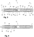
- FIGS 3 and 4 show a cross section of the drilling assembly 11 in drilling and flushing modes respectively.
- the drilling assembly 11 is shown to have a solid piston 19 design as described in more detail in patent application EP 3 409 878 , it should however be understood that the exhaust assembly disclosed herein could be applied to any other type of DTH drilling assembly construction.
- the drilling assembly 11 comprises an elongate casing 15, which may be a relatively simple sleeve-like frame piece in the form of a substantially hollow cylinder.
- a top sub (or connection piece) 80 by means of which the drilling assembly 11 can be connected to a drill tube (not shown).
- the top sub 80 is at least partially accommodated within the top end 42 of the casing 15.
- the top sub 80 may comprise a threaded connecting surface 23.
- a drill tube adapter 16 comes above and around the top sub 80 and, the drill tube adapter 16 may also comprise a threated connection surface 17.
- the top sub 80 has an inlet port 18 for feeding pressurized fluid to an impact device 13.
- the drill tube adapter 16 comprises an air passage 34 (central bore in the drill tube adapter 16) that is connected to the air supply passage 26 of the top sub 80.
- the inlet port 18 may comprise a valve means 18a, which allows feeding of fluid towards the impact device but prevents flow in an opposite direction.
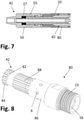
- Figure 8 shows a schematic drawing of the top sub 80.
- a retaining shoulder 82 which extends axially outwards from the body of the top sub 80 and acts to retain the top sub 80 to an exhaust cover 46.
- the top sub 80 has a first bearing surface 84 towards the top end of the top sub 80, preferably positioned above the retaining shoulder 82 and a second bearing surface 86 positioned on the opposite side of the retaining shoulder 82 compared to the first bearing surface 84.
- the bearing surfaces 84, 86 are substantially cylindrical, the first bearing surface 84 has splines machined from the cylindrical surface. When combined the first and second bearing surfaces 84, 86 form a guidance feature which ensures that the exhaust valve remains correctly aligned so that it is able to either fully open or close the connection between the at least one exhaust passage and the at least one exhaust port when switching between drilling and flushing modes respectively.
- At least one exhaust passage 56 extends longitudinally through the top sub 80.
- the exhaust passage 56 connects to a top chamber 21 via at least one top vent passage 63 and then continues outwardly to engage with the exhaust cover 46.
- the top sub 80 moves with respect to the drill string 9, whereas the drill tube adapter 16 and exhaust cover 46 remain in a fixed position with respect to the drill string 9.
- the top sub 80 has a central bore 26 extending longitudinally through for the air supply to pass through.
- the top sub 80 further comprises at least one exhaust passage 56 which is located outside of the central bore and a valve 57 located on its periphery towards the exterior of the drilling assembly 11.
- the top sub 80 is threaded to the piston casing 15.
- the piston 19, which is substantially an elongated cylinder extends axially within the casing 15 and is capable of shuffling back and forth longitudinally through the DTH drilling assembly 11.
- an impact surface ISA arranged to strike an impact surface ISB at a top end 42 of a drill bit 14.
- the piston 19 is a solid-core piece, whereby it is without any through channels or openings in axial and transverse directions.
- the top working chamber 21 At the top end 42 side of the piston 19 is the top working chamber 21 and at the opposite end side is a bottom working chamber 22. Movement of the piston 19 is configured to feed and discharge the working chambers 21, 22 and to thereby cause the piston 19 to move towards an impact direction A and return direction B.
- an exhaust system 58 which comprises an exhaust cover 46 and at least one exhaust port 55.
- the exhaust cover 46 is engaged with the drill tube adapter 16 by a threaded connection.
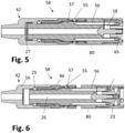
- a retaining ring 25 is positioned between the exhaust cover 46 and the tube adapter 16 (shown on figure 6 ) to limit the axial movement of the top sub 80.
- the at least one exhaust port 55 extends radially through the exhaust cover 46.
- the at least one exhaust port 55 is open to the exterior of the drilling assembly 11.
- the exhaust cover 46 and the top sub 80 are connected in a way so that that are able to slide together and apart longitudinally using an engaging feature, for example this could be done by means of a plurality of splines 88 positioned on the top sub 80. This means that torque can be transmitted from the exhaust cover 46 to the top sub 80 from the spline connection (not shown on drawing) or alternative engaging system whilst axial movement is limited.
- the bottom chamber 22 is exhausted from the bottom end 44 of the drilling assembly through at least one flushing port 59 to remove cuttings from the drill bit face.
- the bottom chamber 22 is connected to the at least one flushing port 59 via at least one bottom vent passage 64.
- the top chamber 21 is fluidly connected to at least one top vent passage 63, which fluidly connects to the at least one exhaust passage 56 and then the top chamber 21 is exhausted through the at least one exhaust port 55 positioned in the exhaust cover 46.
- the at least one exhaust port 55 is able to open and close when switched between drilling mode and flushing mode.
- the exhaust system 58 is moved forward relative to the drill string 9.
- the opening and closing of the at least one exhaust port 55 is enabled by the presence of at least one exhaust valve 57 positioned on the top sub 80.
- the exhaust system 58 is located next to the drill string 9 and so the exhaust value 57 is positioned so that the exhaust ports 55 are open, in other words the at least one exhaust port is in fluid connection with the at least one exhaust passage 56.
- the exhaust system 58 When the drilling assembly 11 is in flushing mode the exhaust system 58 is positioned forward of the drill string 9 and therefore the at least one exhaust value 57 is positioned so that the at least one exhaust port 55 is closed.
- the at least one exhaust port 55 By closing the at least one exhaust port 55 when the drilling assembly 11 is in flushing mode all the air is directed through the drill bit which improves the effectiveness of the hole cleaning and prevents contamination of the hammer.
- the at least one exhaust ports 55 in the exhaust cover 46 are opened and closed to the exterior of the drilling assembly 11 by the at least one exhaust valve 57.
- Figure 5 shows an enlargement of the top end 42 of the drilling assembly 11 when in drilling mode.
- the at least one exhaust valve 57 is positioned so that the at least one exhaust passage 56 and the at least one exhaust port 55 are connected and so the pressurized fluid is exhausted to the exterior.
- Figure 6 shows an enlargement of the top end 42 of the drilling assembly 11 when in flushing mode.
- the at least one exhaust valve 57 is positioned so that the at least one exhaust port 55 is blocked off from the at least one exhaust passage 56. This means that all the flushing air is directed through the drill bit.
- FIG. 7 shows that optionally, a damping device 27 may be added between the top sub 80 and the drill tube adapter 16.
- the damping device 27 or element must be suitable for absorbing shock and vibration caused from the drilling operation and could for example be made from an elastic material such as polyurethane or rubber.
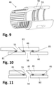
- Figures 10 and 11 show an enlargement of the interface between the exhaust cover 46 and the top sub 80 in flushing and drilling modes respectively wherein at least one seal 81,83,85 is positioned on both sides of the at least one exhaust port 55.
- the seals are scraper / washer seal type seals.
- three seals 81, 83, 85 are used.
- the first seal 81 and the second seal 83 block off the sides of the exhaust port 55 and the second seal 83 and third seal 85 block off the sides of the exhaust passage 56 to prevent contamination from dirt and debris entering the drilling assembly 11.
- the first seal 81 and the second seal 83 block off the sides of the exhaust port 55 and exhaust passage 56 and in this position the third seal 85 is redundant.
- Figure 9 shows the exhaust cover 46.
- the groove 90 extends beyond both sides of the exhaust port 55 and has a curved radius.
- the angle of the exhaust port 55 is inclined at an angle of ⁇ 90° with respect to the longitudinal axis 2 of the drilling assembly 11 that is oriented towards the drill bit 14.
- the check valve 65 there is a check valve 65 between the top chamber 21 and the at least one exhaust port 55.
- the check valve 65 is made from a deformable rubber or with a spring.
Landscapes
- Engineering & Computer Science (AREA)
- Life Sciences & Earth Sciences (AREA)
- Geology (AREA)
- Mining & Mineral Resources (AREA)
- Mechanical Engineering (AREA)
- Physics & Mathematics (AREA)
- Environmental & Geological Engineering (AREA)
- Fluid Mechanics (AREA)
- General Life Sciences & Earth Sciences (AREA)
- Geochemistry & Mineralogy (AREA)
- Earth Drilling (AREA)
Claims (13)
- Bohranordnung (11) zum Bohren im Loch, die ein oberes Ende (42) aufweist, das angeordnet ist zum Koppeln eines Bohrgestänges (9), und ein unteres schneidendes Ende (44), wobei die Bohranordnung (11) Folgendes umfasst:einen Bohrrohradapter (16), der an dem oberen Ende (42) der Anordnung positioniert ist;ein längliches Gehäuse (15);eine Bohrspitze (14), die mindestens teilweise innerhalb des unteren Endes (44) des Gehäuses (15) untergebracht ist;einen fluidbetriebenen Kolben (19), der innerhalb des Gehäuses (15) bewegbar angeordnet ist, der fähig ist, sich axial rückwärts und vorwärts zu bewegen;eine obere Arbeitskammer (21) an der oberen Endseite des Kolbens (19);eine untere Arbeitskammer (22) an der unteren Endseite des Kolbens (19);einen oberen Unterbereich (80), der eine Sicherungsschulter (82), eine Vielzahl von Längsnuten (88), mindestens einen Abgasdurchgang (56), der im Gehäuse (15) eingerastet ist, umfasst, wobei der mindestens eine Abgasdurchgang (56) mit der oberen Kammer (21) über mindestens einen oberen Entlüftungsdurchgang (63) verbunden ist;mindestens einen Spülanschluss (59) an dem unteren Ende des Gehäuses (15), der mit dem mindestens einen unteren Entlüftungsdurchgang (64) verbunden ist, der angeordnet ist, um die untere Kammer (22) zu entlüften;ein Abgassystem (58) an dem oberen Ende des Gehäuses (15), das eine Abgasabdeckung (46) und mindestens einen Abgasanschluss (55) umfasst, der angeordnet ist, um die obere Kammer (21) über den mindestens einen Abgasdurchgang (56) zu entlüften,dadurch gekennzeichnet, dass:
das Abgassystem (58) in Bezug auf das Bohrgestänge (9) bewegbar ist und der obere Unterbereich (80) ein Abgasventil (57) umfasst, das fähig ist, die Verbindung zwischen dem mindestens einen Abgasdurchgang (56) und dem mindestens einen Abgasanschluss (55) zu öffnen und zu schließen. - Bohranordnung zum Bohren im Loch nach Anspruch 1, wobei das Abgasventil (57) so positioniert ist, dass die Verbindung zwischen dem mindestens einen Abgasdurchgang (56) und dem mindestens einen Abgasanschluss (55) offen ist, wenn sich die Bohranordnung im Bohrbetrieb befindet.
- Bohranordnung zum Bohren im Loch nach Anspruch 1, wobei das Abgasventil (57) so positioniert ist, dass die Verbindung zwischen dem mindestens einen Abgasdurchgang (56) und dem mindestens einen Abgasanschluss (55) geschlossen ist, wenn sich die Bohranordnung im Spülbetrieb befindet.
- Bohranordnung (11) zum Bohren im Loch nach einem der vorstehenden Ansprüche, wobei eine Einrastfunktion vorhanden ist, wie eine Längsnutenverbindung (24) zwischen der Abgasabdeckung (46) und dem oberen Unterbereich (80), die es erlaubt, dass die Abgasabdeckung (46) und der obere Unterbereich (80) der Länge nach zwischen einer ersten Position und einer zweiten Position gleiten.
- Maschine (11) zum Bohren im Loch, nach einem der vorstehenden Ansprüche, wobei mindestens eine Dichtung (81, 83, 85) an beiden Seiten des mindestens einen Abgasanschlusses (55) eingesetzt ist.
- Maschine (11) zum Bohren im Loch nach Anspruch 5, wobei ein Minimum von 3 Dichtungen (81, 83, 85) vorhanden ist.
- Maschine (11) zum Bohren im Loch, nach einem der vorstehenden Ansprüche, wobei zwischen dem oberen Unterbereich (80) und dem Bohrrohradapter (16) eine Dämpfvorrichtung (27) positioniert ist.
- Maschine (11) zum Bohren im Loch, nach einem der vorstehenden Ansprüche, wobei der obere Unterbereich (80) eine Führungsfunktion (82, 86) aufweist.
- Maschine (11) zum Bohren im Loch, nach einem der vorstehenden Ansprüche, wobei in der Abgasabdeckung (46) eine Rille (90) vorhanden ist, die den mindestens einen Abgasanschluss (55) umgibt.
- Maschine zum Bohren im Loch (1), nach einem der vorstehenden Ansprüche, wobei der Winkel des Abgasanschlusses (55) um einem Winkel von ≥ 90° in Bezug auf die Längsachse (2) der Bohranordnung (11), die in Richtung der Bohrspitze (14) ausgerichtet ist, geneigt ist.
- Maschine (11) zum Bohren im Loch, nach einem der vorstehenden Ansprüche, wobei das Fluid über eine Vielzahl von Fluiddurchgängen (28), die zwischen der Innenoberfläche des Gehäuses (15) und der Außenoberfläche der Regelmuffe (20) gebildet sind, in die Arbeitskammern (21, 22) eingespeist und daraus abgelassen wird.
- Maschine (11) zum Bohren im Loch, nach einem der vorstehenden Ansprüche, wobei zwischen der oberen Kammer (21) und dem Abgasanschluss (56) ein Rückschlagventil (65) vorhanden ist.
- Bohrvorrichtung zum Schlagbohren von Gestein, umfassend:
ein Bohrgestänge (9), das aus einer Vielzahl von durchgängig gekoppelten Bohrrohren gebildet ist; und eine Bohranordnung (11) nach einem vorstehenden Anspruch, die lösbar an einem axial vorderen Ende des Bohrgestänges befestigt ist.
Priority Applications (9)
| Application Number | Priority Date | Filing Date | Title |
|---|---|---|---|
| EP19181470.6A EP3754152B1 (de) | 2019-06-20 | 2019-06-20 | Abgasanlage für maschinenanordnung zum bohren im loch |
| CA3136703A CA3136703C (en) | 2019-06-20 | 2020-06-18 | Down the hole drilling assembly exhaust assembly |
| CN202080036729.8A CN113840976B (zh) | 2019-06-20 | 2020-06-18 | 潜孔钻凿组件排放组件 |
| PCT/EP2020/066860 WO2020254458A1 (en) | 2019-06-20 | 2020-06-18 | Down the hole drilling assembly exhaust assembly |
| AU2020294917A AU2020294917B2 (en) | 2019-06-20 | 2020-06-18 | Down the hole drilling assembly exhaust assembly |
| KR1020217040788A KR102857070B1 (ko) | 2019-06-20 | 2020-06-18 | 다운더홀 드릴링 어셈블리 배기 어셈블리 |
| US17/619,308 US11946328B2 (en) | 2019-06-20 | 2020-06-18 | Down the hole drilling assembly exhaust assembly |
| MX2021015682A MX2021015682A (es) | 2019-06-20 | 2020-06-18 | Ensamble de escape para ensamble de perforacion en fondo. |
| ZA2021/07703A ZA202107703B (en) | 2019-06-20 | 2021-10-12 | Down the hole drilling assembly exhaust assembly |
Applications Claiming Priority (1)
| Application Number | Priority Date | Filing Date | Title |
|---|---|---|---|
| EP19181470.6A EP3754152B1 (de) | 2019-06-20 | 2019-06-20 | Abgasanlage für maschinenanordnung zum bohren im loch |
Publications (2)
| Publication Number | Publication Date |
|---|---|
| EP3754152A1 EP3754152A1 (de) | 2020-12-23 |
| EP3754152B1 true EP3754152B1 (de) | 2022-02-16 |
Family
ID=66999726
Family Applications (1)
| Application Number | Title | Priority Date | Filing Date |
|---|---|---|---|
| EP19181470.6A Active EP3754152B1 (de) | 2019-06-20 | 2019-06-20 | Abgasanlage für maschinenanordnung zum bohren im loch |
Country Status (8)
| Country | Link |
|---|---|
| US (1) | US11946328B2 (de) |
| EP (1) | EP3754152B1 (de) |
| KR (1) | KR102857070B1 (de) |
| CN (1) | CN113840976B (de) |
| AU (1) | AU2020294917B2 (de) |
| MX (1) | MX2021015682A (de) |
| WO (1) | WO2020254458A1 (de) |
| ZA (1) | ZA202107703B (de) |
Families Citing this family (1)
| Publication number | Priority date | Publication date | Assignee | Title |
|---|---|---|---|---|
| AU2022267017A1 (en) * | 2021-04-29 | 2023-12-07 | Mincon International Limited | Hydraulic down-the-hole hammer and subsea pile |
Family Cites Families (15)
| Publication number | Priority date | Publication date | Assignee | Title |
|---|---|---|---|---|
| US9068399B2 (en) * | 2006-10-20 | 2015-06-30 | Drillroc Pneumatic Pty Ltd | Down-the-hole hammer drill |
| US7921941B2 (en) * | 2008-01-28 | 2011-04-12 | Drillco Tools S.A. | Pressurized fluid flow system for a reverse circulation hammer |
| US8640794B2 (en) * | 2008-01-28 | 2014-02-04 | Drillco Tools S.A. | Pressurized fluid flow system for a normal circulation hammer and hammer thereof |
| US8800690B2 (en) * | 2008-03-31 | 2014-08-12 | Center Rock Inc. | Down-the-hole drill hammer having a reverse exhaust system and segmented chuck assembly |
| US8302707B2 (en) * | 2009-01-28 | 2012-11-06 | Center Rock Inc. | Down-the-hole drill reverse exhaust system |
| US8622152B2 (en) * | 2009-01-28 | 2014-01-07 | Center Rock Inc. | Down-the-hole drill hammer having a sliding exhaust check valve |
| US8011455B2 (en) * | 2009-02-11 | 2011-09-06 | Atlas Copco Secoroc Llc | Down hole hammer having elevated exhaust |
| AU2009357364B2 (en) | 2009-12-22 | 2014-01-16 | Suk Sin In | Air hammer for a boring machine |
| IES20100666A2 (en) | 2010-10-15 | 2011-06-22 | Minroc Techn Promotions Ltd | A down-the-hole hammer |
| CN104278949B (zh) | 2013-07-04 | 2018-07-27 | 德里尔科工具股份有限公司 | 用于反循环潜孔锤的加压流体流动系统和反循环潜孔锤 |
| US10316586B1 (en) * | 2016-12-14 | 2019-06-11 | Jaime Andres AROS | Pressurized fluid flow system for a DTH hammer and normal circulation hammer thereof |
| EP3409879B1 (de) * | 2017-06-02 | 2019-11-20 | Sandvik Intellectual Property AB | Imlochbohrmaschine und verfahren zum bohren von gestein |
| EP3409878B1 (de) * | 2017-06-02 | 2021-08-18 | Sandvik Intellectual Property AB | Imlochbohrmaschine und verfahren zum bohren von gestein |
| MX2020006063A (es) * | 2017-12-13 | 2020-08-24 | Jaime Andres Aros | Sistema de flujo de fluido presurizado con multiples camaras de trabajo para un martillo de fondo y un martillo de fondo de circulacion normal con dicho sistema. |
| EP3754153B1 (de) * | 2019-06-20 | 2022-05-04 | Sandvik Mining and Construction Oy | Abwärtsbohranordnung und vorrichtung |
-
2019
- 2019-06-20 EP EP19181470.6A patent/EP3754152B1/de active Active
-
2020
- 2020-06-18 US US17/619,308 patent/US11946328B2/en active Active
- 2020-06-18 KR KR1020217040788A patent/KR102857070B1/ko active Active
- 2020-06-18 WO PCT/EP2020/066860 patent/WO2020254458A1/en not_active Ceased
- 2020-06-18 MX MX2021015682A patent/MX2021015682A/es unknown
- 2020-06-18 AU AU2020294917A patent/AU2020294917B2/en active Active
- 2020-06-18 CN CN202080036729.8A patent/CN113840976B/zh active Active
-
2021
- 2021-10-12 ZA ZA2021/07703A patent/ZA202107703B/en unknown
Also Published As
| Publication number | Publication date |
|---|---|
| MX2021015682A (es) | 2022-02-03 |
| AU2020294917B2 (en) | 2025-03-20 |
| EP3754152A1 (de) | 2020-12-23 |
| CN113840976A (zh) | 2021-12-24 |
| KR102857070B1 (ko) | 2025-09-08 |
| AU2020294917A1 (en) | 2021-12-16 |
| WO2020254458A1 (en) | 2020-12-24 |
| CN113840976B (zh) | 2024-04-30 |
| KR20220019702A (ko) | 2022-02-17 |
| US20220098943A1 (en) | 2022-03-31 |
| CA3136703A1 (en) | 2020-12-24 |
| ZA202107703B (en) | 2025-04-30 |
| US11946328B2 (en) | 2024-04-02 |
Similar Documents
| Publication | Publication Date | Title |
|---|---|---|
| CA2752108A1 (en) | Down hole hammer having elevated exhaust | |
| US12006771B2 (en) | Down-the-hole hammer drill bit assembly | |
| AU2020294917B2 (en) | Down the hole drilling assembly exhaust assembly | |
| CA3116113A1 (en) | Rock drill bit for percussive drilling | |
| CA3136703C (en) | Down the hole drilling assembly exhaust assembly | |
| AU2020295661B2 (en) | Down the hole drilling assembly and apparatus | |
| US12196059B2 (en) | Spline lubrication for DTH hammers | |
| EP4372201A1 (de) | Komplett abgedichteter bohrlochhammer | |
| CA3268858A1 (en) | Fully sealed down the hole hammer | |
| CA3116111C (en) | Down-the-hole hammer drill bit assembly |
Legal Events
| Date | Code | Title | Description |
|---|---|---|---|
| PUAI | Public reference made under article 153(3) epc to a published international application that has entered the european phase |
Free format text: ORIGINAL CODE: 0009012 |
|
| STAA | Information on the status of an ep patent application or granted ep patent |
Free format text: STATUS: THE APPLICATION HAS BEEN PUBLISHED |
|
| AK | Designated contracting states |
Kind code of ref document: A1 Designated state(s): AL AT BE BG CH CY CZ DE DK EE ES FI FR GB GR HR HU IE IS IT LI LT LU LV MC MK MT NL NO PL PT RO RS SE SI SK SM TR |
|
| AX | Request for extension of the european patent |
Extension state: BA ME |
|
| STAA | Information on the status of an ep patent application or granted ep patent |
Free format text: STATUS: REQUEST FOR EXAMINATION WAS MADE |
|
| 17P | Request for examination filed |
Effective date: 20210623 |
|
| RBV | Designated contracting states (corrected) |
Designated state(s): AL AT BE BG CH CY CZ DE DK EE ES FI FR GB GR HR HU IE IS IT LI LT LU LV MC MK MT NL NO PL PT RO RS SE SI SK SM TR |
|
| GRAP | Despatch of communication of intention to grant a patent |
Free format text: ORIGINAL CODE: EPIDOSNIGR1 |
|
| STAA | Information on the status of an ep patent application or granted ep patent |
Free format text: STATUS: GRANT OF PATENT IS INTENDED |
|
| INTG | Intention to grant announced |
Effective date: 20211027 |
|
| GRAS | Grant fee paid |
Free format text: ORIGINAL CODE: EPIDOSNIGR3 |
|
| GRAJ | Information related to disapproval of communication of intention to grant by the applicant or resumption of examination proceedings by the epo deleted |
Free format text: ORIGINAL CODE: EPIDOSDIGR1 |
|
| GRAL | Information related to payment of fee for publishing/printing deleted |
Free format text: ORIGINAL CODE: EPIDOSDIGR3 |
|
| STAA | Information on the status of an ep patent application or granted ep patent |
Free format text: STATUS: REQUEST FOR EXAMINATION WAS MADE |
|
| GRAP | Despatch of communication of intention to grant a patent |
Free format text: ORIGINAL CODE: EPIDOSNIGR1 |
|
| STAA | Information on the status of an ep patent application or granted ep patent |
Free format text: STATUS: GRANT OF PATENT IS INTENDED |
|
| GRAF | Information related to payment of grant fee modified |
Free format text: ORIGINAL CODE: EPIDOSCIGR3 |
|
| INTC | Intention to grant announced (deleted) | ||
| GRAA | (expected) grant |
Free format text: ORIGINAL CODE: 0009210 |
|
| STAA | Information on the status of an ep patent application or granted ep patent |
Free format text: STATUS: THE PATENT HAS BEEN GRANTED |
|
| INTG | Intention to grant announced |
Effective date: 20220103 |
|
| AK | Designated contracting states |
Kind code of ref document: B1 Designated state(s): AL AT BE BG CH CY CZ DE DK EE ES FI FR GB GR HR HU IE IS IT LI LT LU LV MC MK MT NL NO PL PT RO RS SE SI SK SM TR |
|
| REG | Reference to a national code |
Ref country code: GB Ref legal event code: FG4D |
|
| REG | Reference to a national code |
Ref country code: CH Ref legal event code: EP |
|
| REG | Reference to a national code |
Ref country code: DE Ref legal event code: R096 Ref document number: 602019011598 Country of ref document: DE |
|
| REG | Reference to a national code |
Ref country code: FI Ref legal event code: FGE |
|
| REG | Reference to a national code |
Ref country code: AT Ref legal event code: REF Ref document number: 1468989 Country of ref document: AT Kind code of ref document: T Effective date: 20220315 |
|
| REG | Reference to a national code |
Ref country code: IE Ref legal event code: FG4D |
|
| REG | Reference to a national code |
Ref country code: SE Ref legal event code: TRGR |
|
| REG | Reference to a national code |
Ref country code: LT Ref legal event code: MG9D |
|
| REG | Reference to a national code |
Ref country code: NL Ref legal event code: MP Effective date: 20220216 |
|
| PG25 | Lapsed in a contracting state [announced via postgrant information from national office to epo] |
Ref country code: RS Free format text: LAPSE BECAUSE OF FAILURE TO SUBMIT A TRANSLATION OF THE DESCRIPTION OR TO PAY THE FEE WITHIN THE PRESCRIBED TIME-LIMIT Effective date: 20220216 Ref country code: PT Free format text: LAPSE BECAUSE OF FAILURE TO SUBMIT A TRANSLATION OF THE DESCRIPTION OR TO PAY THE FEE WITHIN THE PRESCRIBED TIME-LIMIT Effective date: 20220616 Ref country code: NO Free format text: LAPSE BECAUSE OF FAILURE TO SUBMIT A TRANSLATION OF THE DESCRIPTION OR TO PAY THE FEE WITHIN THE PRESCRIBED TIME-LIMIT Effective date: 20220516 Ref country code: NL Free format text: LAPSE BECAUSE OF FAILURE TO SUBMIT A TRANSLATION OF THE DESCRIPTION OR TO PAY THE FEE WITHIN THE PRESCRIBED TIME-LIMIT Effective date: 20220216 Ref country code: LT Free format text: LAPSE BECAUSE OF FAILURE TO SUBMIT A TRANSLATION OF THE DESCRIPTION OR TO PAY THE FEE WITHIN THE PRESCRIBED TIME-LIMIT Effective date: 20220216 Ref country code: HR Free format text: LAPSE BECAUSE OF FAILURE TO SUBMIT A TRANSLATION OF THE DESCRIPTION OR TO PAY THE FEE WITHIN THE PRESCRIBED TIME-LIMIT Effective date: 20220216 Ref country code: ES Free format text: LAPSE BECAUSE OF FAILURE TO SUBMIT A TRANSLATION OF THE DESCRIPTION OR TO PAY THE FEE WITHIN THE PRESCRIBED TIME-LIMIT Effective date: 20220216 Ref country code: BG Free format text: LAPSE BECAUSE OF FAILURE TO SUBMIT A TRANSLATION OF THE DESCRIPTION OR TO PAY THE FEE WITHIN THE PRESCRIBED TIME-LIMIT Effective date: 20220516 |
|
| PG25 | Lapsed in a contracting state [announced via postgrant information from national office to epo] |
Ref country code: PL Free format text: LAPSE BECAUSE OF FAILURE TO SUBMIT A TRANSLATION OF THE DESCRIPTION OR TO PAY THE FEE WITHIN THE PRESCRIBED TIME-LIMIT Effective date: 20220216 Ref country code: LV Free format text: LAPSE BECAUSE OF FAILURE TO SUBMIT A TRANSLATION OF THE DESCRIPTION OR TO PAY THE FEE WITHIN THE PRESCRIBED TIME-LIMIT Effective date: 20220216 Ref country code: GR Free format text: LAPSE BECAUSE OF FAILURE TO SUBMIT A TRANSLATION OF THE DESCRIPTION OR TO PAY THE FEE WITHIN THE PRESCRIBED TIME-LIMIT Effective date: 20220517 |
|
| PG25 | Lapsed in a contracting state [announced via postgrant information from national office to epo] |
Ref country code: IS Free format text: LAPSE BECAUSE OF FAILURE TO SUBMIT A TRANSLATION OF THE DESCRIPTION OR TO PAY THE FEE WITHIN THE PRESCRIBED TIME-LIMIT Effective date: 20220617 |
|
| PG25 | Lapsed in a contracting state [announced via postgrant information from national office to epo] |
Ref country code: SM Free format text: LAPSE BECAUSE OF FAILURE TO SUBMIT A TRANSLATION OF THE DESCRIPTION OR TO PAY THE FEE WITHIN THE PRESCRIBED TIME-LIMIT Effective date: 20220216 Ref country code: SK Free format text: LAPSE BECAUSE OF FAILURE TO SUBMIT A TRANSLATION OF THE DESCRIPTION OR TO PAY THE FEE WITHIN THE PRESCRIBED TIME-LIMIT Effective date: 20220216 Ref country code: RO Free format text: LAPSE BECAUSE OF FAILURE TO SUBMIT A TRANSLATION OF THE DESCRIPTION OR TO PAY THE FEE WITHIN THE PRESCRIBED TIME-LIMIT Effective date: 20220216 Ref country code: EE Free format text: LAPSE BECAUSE OF FAILURE TO SUBMIT A TRANSLATION OF THE DESCRIPTION OR TO PAY THE FEE WITHIN THE PRESCRIBED TIME-LIMIT Effective date: 20220216 Ref country code: DK Free format text: LAPSE BECAUSE OF FAILURE TO SUBMIT A TRANSLATION OF THE DESCRIPTION OR TO PAY THE FEE WITHIN THE PRESCRIBED TIME-LIMIT Effective date: 20220216 Ref country code: CZ Free format text: LAPSE BECAUSE OF FAILURE TO SUBMIT A TRANSLATION OF THE DESCRIPTION OR TO PAY THE FEE WITHIN THE PRESCRIBED TIME-LIMIT Effective date: 20220216 |
|
| REG | Reference to a national code |
Ref country code: DE Ref legal event code: R097 Ref document number: 602019011598 Country of ref document: DE |
|
| PG25 | Lapsed in a contracting state [announced via postgrant information from national office to epo] |
Ref country code: AL Free format text: LAPSE BECAUSE OF FAILURE TO SUBMIT A TRANSLATION OF THE DESCRIPTION OR TO PAY THE FEE WITHIN THE PRESCRIBED TIME-LIMIT Effective date: 20220216 |
|
| PLBE | No opposition filed within time limit |
Free format text: ORIGINAL CODE: 0009261 |
|
| STAA | Information on the status of an ep patent application or granted ep patent |
Free format text: STATUS: NO OPPOSITION FILED WITHIN TIME LIMIT |
|
| REG | Reference to a national code |
Ref country code: DE Ref legal event code: R119 Ref document number: 602019011598 Country of ref document: DE |
|
| 26N | No opposition filed |
Effective date: 20221117 |
|
| PG25 | Lapsed in a contracting state [announced via postgrant information from national office to epo] |
Ref country code: MC Free format text: LAPSE BECAUSE OF FAILURE TO SUBMIT A TRANSLATION OF THE DESCRIPTION OR TO PAY THE FEE WITHIN THE PRESCRIBED TIME-LIMIT Effective date: 20220216 |
|
| REG | Reference to a national code |
Ref country code: CH Ref legal event code: PL |
|
| REG | Reference to a national code |
Ref country code: BE Ref legal event code: MM Effective date: 20220630 |
|
| PG25 | Lapsed in a contracting state [announced via postgrant information from national office to epo] |
Ref country code: SI Free format text: LAPSE BECAUSE OF FAILURE TO SUBMIT A TRANSLATION OF THE DESCRIPTION OR TO PAY THE FEE WITHIN THE PRESCRIBED TIME-LIMIT Effective date: 20220216 |
|
| PG25 | Lapsed in a contracting state [announced via postgrant information from national office to epo] |
Ref country code: LU Free format text: LAPSE BECAUSE OF NON-PAYMENT OF DUE FEES Effective date: 20220620 Ref country code: LI Free format text: LAPSE BECAUSE OF NON-PAYMENT OF DUE FEES Effective date: 20220630 Ref country code: FR Free format text: LAPSE BECAUSE OF NON-PAYMENT OF DUE FEES Effective date: 20220630 Ref country code: CH Free format text: LAPSE BECAUSE OF NON-PAYMENT OF DUE FEES Effective date: 20220630 |
|
| PG25 | Lapsed in a contracting state [announced via postgrant information from national office to epo] |
Ref country code: DE Free format text: LAPSE BECAUSE OF NON-PAYMENT OF DUE FEES Effective date: 20230103 Ref country code: BE Free format text: LAPSE BECAUSE OF NON-PAYMENT OF DUE FEES Effective date: 20220630 |
|
| PG25 | Lapsed in a contracting state [announced via postgrant information from national office to epo] |
Ref country code: IT Free format text: LAPSE BECAUSE OF FAILURE TO SUBMIT A TRANSLATION OF THE DESCRIPTION OR TO PAY THE FEE WITHIN THE PRESCRIBED TIME-LIMIT Effective date: 20220216 |
|
| PG25 | Lapsed in a contracting state [announced via postgrant information from national office to epo] |
Ref country code: MK Free format text: LAPSE BECAUSE OF FAILURE TO SUBMIT A TRANSLATION OF THE DESCRIPTION OR TO PAY THE FEE WITHIN THE PRESCRIBED TIME-LIMIT Effective date: 20220216 Ref country code: CY Free format text: LAPSE BECAUSE OF FAILURE TO SUBMIT A TRANSLATION OF THE DESCRIPTION OR TO PAY THE FEE WITHIN THE PRESCRIBED TIME-LIMIT Effective date: 20220216 |
|
| PG25 | Lapsed in a contracting state [announced via postgrant information from national office to epo] |
Ref country code: HU Free format text: LAPSE BECAUSE OF FAILURE TO SUBMIT A TRANSLATION OF THE DESCRIPTION OR TO PAY THE FEE WITHIN THE PRESCRIBED TIME-LIMIT; INVALID AB INITIO Effective date: 20190620 |
|
| PG25 | Lapsed in a contracting state [announced via postgrant information from national office to epo] |
Ref country code: MT Free format text: LAPSE BECAUSE OF FAILURE TO SUBMIT A TRANSLATION OF THE DESCRIPTION OR TO PAY THE FEE WITHIN THE PRESCRIBED TIME-LIMIT Effective date: 20220216 |
|
| PG25 | Lapsed in a contracting state [announced via postgrant information from national office to epo] |
Ref country code: TR Free format text: LAPSE BECAUSE OF FAILURE TO SUBMIT A TRANSLATION OF THE DESCRIPTION OR TO PAY THE FEE WITHIN THE PRESCRIBED TIME-LIMIT Effective date: 20220216 |
|
| PGFP | Annual fee paid to national office [announced via postgrant information from national office to epo] |
Ref country code: GB Payment date: 20260507 Year of fee payment: 8 |
|
| PGFP | Annual fee paid to national office [announced via postgrant information from national office to epo] |
Ref country code: AT Payment date: 20260527 Year of fee payment: 8 Ref country code: SE Payment date: 20260511 Year of fee payment: 8 Ref country code: FI Payment date: 20260623 Year of fee payment: 8 |
|
| PGFP | Annual fee paid to national office [announced via postgrant information from national office to epo] |
Ref country code: IE Payment date: 20260514 Year of fee payment: 8 |