EP3753999B1 - Semi-continous hydrothermal reaction system - Google Patents
Semi-continous hydrothermal reaction system Download PDFInfo
- Publication number
- EP3753999B1 EP3753999B1 EP19181129.8A EP19181129A EP3753999B1 EP 3753999 B1 EP3753999 B1 EP 3753999B1 EP 19181129 A EP19181129 A EP 19181129A EP 3753999 B1 EP3753999 B1 EP 3753999B1
- Authority
- EP
- European Patent Office
- Prior art keywords
- reaction solution
- individual
- hydrothermal
- reaction
- hydrothermal reactor
- Prior art date
- Legal status (The legal status is an assumption and is not a legal conclusion. Google has not performed a legal analysis and makes no representation as to the accuracy of the status listed.)
- Active
Links
Images


Classifications
-
- C—CHEMISTRY; METALLURGY
- C10—PETROLEUM, GAS OR COKE INDUSTRIES; TECHNICAL GASES CONTAINING CARBON MONOXIDE; FUELS; LUBRICANTS; PEAT
- C10G—CRACKING HYDROCARBON OILS; PRODUCTION OF LIQUID HYDROCARBON MIXTURES, e.g. BY DESTRUCTIVE HYDROGENATION, OLIGOMERISATION, POLYMERISATION; RECOVERY OF HYDROCARBON OILS FROM OIL-SHALE, OIL-SAND, OR GASES; REFINING MIXTURES MAINLY CONSISTING OF HYDROCARBONS; REFORMING OF NAPHTHA; MINERAL WAXES
- C10G1/00—Production of liquid hydrocarbon mixtures from oil-shale, oil-sand, or non-melting solid carbonaceous or similar materials, e.g. wood, coal
- C10G1/008—Controlling or regulating of liquefaction processes
-
- B—PERFORMING OPERATIONS; TRANSPORTING
- B01—PHYSICAL OR CHEMICAL PROCESSES OR APPARATUS IN GENERAL
- B01J—CHEMICAL OR PHYSICAL PROCESSES, e.g. CATALYSIS OR COLLOID CHEMISTRY; THEIR RELEVANT APPARATUS
- B01J19/00—Chemical, physical or physico-chemical processes in general; Their relevant apparatus
- B01J19/0006—Controlling or regulating processes
-
- B—PERFORMING OPERATIONS; TRANSPORTING
- B01—PHYSICAL OR CHEMICAL PROCESSES OR APPARATUS IN GENERAL
- B01J—CHEMICAL OR PHYSICAL PROCESSES, e.g. CATALYSIS OR COLLOID CHEMISTRY; THEIR RELEVANT APPARATUS
- B01J19/00—Chemical, physical or physico-chemical processes in general; Their relevant apparatus
- B01J19/0053—Details of the reactor
- B01J19/0066—Stirrers
-
- B—PERFORMING OPERATIONS; TRANSPORTING
- B01—PHYSICAL OR CHEMICAL PROCESSES OR APPARATUS IN GENERAL
- B01J—CHEMICAL OR PHYSICAL PROCESSES, e.g. CATALYSIS OR COLLOID CHEMISTRY; THEIR RELEVANT APPARATUS
- B01J19/00—Chemical, physical or physico-chemical processes in general; Their relevant apparatus
- B01J19/18—Stationary reactors having moving elements inside
-
- B—PERFORMING OPERATIONS; TRANSPORTING
- B01—PHYSICAL OR CHEMICAL PROCESSES OR APPARATUS IN GENERAL
- B01J—CHEMICAL OR PHYSICAL PROCESSES, e.g. CATALYSIS OR COLLOID CHEMISTRY; THEIR RELEVANT APPARATUS
- B01J19/00—Chemical, physical or physico-chemical processes in general; Their relevant apparatus
- B01J19/18—Stationary reactors having moving elements inside
- B01J19/1856—Stationary reactors having moving elements inside placed in parallel
-
- B—PERFORMING OPERATIONS; TRANSPORTING
- B01—PHYSICAL OR CHEMICAL PROCESSES OR APPARATUS IN GENERAL
- B01J—CHEMICAL OR PHYSICAL PROCESSES, e.g. CATALYSIS OR COLLOID CHEMISTRY; THEIR RELEVANT APPARATUS
- B01J19/00—Chemical, physical or physico-chemical processes in general; Their relevant apparatus
- B01J19/18—Stationary reactors having moving elements inside
- B01J19/1862—Stationary reactors having moving elements inside placed in series
-
- B—PERFORMING OPERATIONS; TRANSPORTING
- B01—PHYSICAL OR CHEMICAL PROCESSES OR APPARATUS IN GENERAL
- B01J—CHEMICAL OR PHYSICAL PROCESSES, e.g. CATALYSIS OR COLLOID CHEMISTRY; THEIR RELEVANT APPARATUS
- B01J19/00—Chemical, physical or physico-chemical processes in general; Their relevant apparatus
- B01J19/24—Stationary reactors without moving elements inside
- B01J19/2445—Stationary reactors without moving elements inside placed in parallel
-
- B—PERFORMING OPERATIONS; TRANSPORTING
- B01—PHYSICAL OR CHEMICAL PROCESSES OR APPARATUS IN GENERAL
- B01J—CHEMICAL OR PHYSICAL PROCESSES, e.g. CATALYSIS OR COLLOID CHEMISTRY; THEIR RELEVANT APPARATUS
- B01J3/00—Processes of utilising sub-atmospheric or super-atmospheric pressure to effect chemical or physical change of matter; Apparatus therefor
- B01J3/008—Processes carried out under supercritical conditions
-
- B—PERFORMING OPERATIONS; TRANSPORTING
- B01—PHYSICAL OR CHEMICAL PROCESSES OR APPARATUS IN GENERAL
- B01J—CHEMICAL OR PHYSICAL PROCESSES, e.g. CATALYSIS OR COLLOID CHEMISTRY; THEIR RELEVANT APPARATUS
- B01J3/00—Processes of utilising sub-atmospheric or super-atmospheric pressure to effect chemical or physical change of matter; Apparatus therefor
- B01J3/04—Pressure vessels, e.g. autoclaves
-
- C—CHEMISTRY; METALLURGY
- C02—TREATMENT OF WATER, WASTE WATER, SEWAGE, OR SLUDGE
- C02F—TREATMENT OF WATER, WASTE WATER, SEWAGE, OR SLUDGE
- C02F1/00—Treatment of water, waste water, or sewage
- C02F1/008—Control or steering systems not provided for elsewhere in subclass C02F
-
- C—CHEMISTRY; METALLURGY
- C02—TREATMENT OF WATER, WASTE WATER, SEWAGE, OR SLUDGE
- C02F—TREATMENT OF WATER, WASTE WATER, SEWAGE, OR SLUDGE
- C02F11/00—Treatment of sludge; Devices therefor
- C02F11/18—Treatment of sludge; Devices therefor by thermal conditioning
-
- C—CHEMISTRY; METALLURGY
- C10—PETROLEUM, GAS OR COKE INDUSTRIES; TECHNICAL GASES CONTAINING CARBON MONOXIDE; FUELS; LUBRICANTS; PEAT
- C10L—FUELS NOT OTHERWISE PROVIDED FOR; NATURAL GAS; SYNTHETIC NATURAL GAS OBTAINED BY PROCESSES NOT COVERED BY SUBCLASSES C10G OR C10K; LIQUIFIED PETROLEUM GAS; USE OF ADDITIVES TO FUELS OR FIRES; FIRE-LIGHTERS
- C10L9/00—Treating solid fuels to improve their combustion
- C10L9/08—Treating solid fuels to improve their combustion by heat treatments, e.g. calcining
- C10L9/086—Hydrothermal carbonization
-
- B—PERFORMING OPERATIONS; TRANSPORTING
- B01—PHYSICAL OR CHEMICAL PROCESSES OR APPARATUS IN GENERAL
- B01J—CHEMICAL OR PHYSICAL PROCESSES, e.g. CATALYSIS OR COLLOID CHEMISTRY; THEIR RELEVANT APPARATUS
- B01J2219/00—Chemical, physical or physico-chemical processes in general; Their relevant apparatus
- B01J2219/00002—Chemical plants
- B01J2219/00027—Process aspects
- B01J2219/00038—Processes in parallel
-
- B—PERFORMING OPERATIONS; TRANSPORTING
- B01—PHYSICAL OR CHEMICAL PROCESSES OR APPARATUS IN GENERAL
- B01J—CHEMICAL OR PHYSICAL PROCESSES, e.g. CATALYSIS OR COLLOID CHEMISTRY; THEIR RELEVANT APPARATUS
- B01J2219/00—Chemical, physical or physico-chemical processes in general; Their relevant apparatus
- B01J2219/00002—Chemical plants
- B01J2219/00027—Process aspects
- B01J2219/0004—Processes in series
-
- B—PERFORMING OPERATIONS; TRANSPORTING
- B01—PHYSICAL OR CHEMICAL PROCESSES OR APPARATUS IN GENERAL
- B01J—CHEMICAL OR PHYSICAL PROCESSES, e.g. CATALYSIS OR COLLOID CHEMISTRY; THEIR RELEVANT APPARATUS
- B01J2219/00—Chemical, physical or physico-chemical processes in general; Their relevant apparatus
- B01J2219/00049—Controlling or regulating processes
-
- B—PERFORMING OPERATIONS; TRANSPORTING
- B01—PHYSICAL OR CHEMICAL PROCESSES OR APPARATUS IN GENERAL
- B01J—CHEMICAL OR PHYSICAL PROCESSES, e.g. CATALYSIS OR COLLOID CHEMISTRY; THEIR RELEVANT APPARATUS
- B01J2219/00—Chemical, physical or physico-chemical processes in general; Their relevant apparatus
- B01J2219/00049—Controlling or regulating processes
- B01J2219/00051—Controlling the temperature
- B01J2219/00074—Controlling the temperature by indirect heating or cooling employing heat exchange fluids
- B01J2219/00087—Controlling the temperature by indirect heating or cooling employing heat exchange fluids with heat exchange elements outside the reactor
- B01J2219/0009—Coils
-
- B—PERFORMING OPERATIONS; TRANSPORTING
- B01—PHYSICAL OR CHEMICAL PROCESSES OR APPARATUS IN GENERAL
- B01J—CHEMICAL OR PHYSICAL PROCESSES, e.g. CATALYSIS OR COLLOID CHEMISTRY; THEIR RELEVANT APPARATUS
- B01J2219/00—Chemical, physical or physico-chemical processes in general; Their relevant apparatus
- B01J2219/00049—Controlling or regulating processes
- B01J2219/00162—Controlling or regulating processes controlling the pressure
-
- B—PERFORMING OPERATIONS; TRANSPORTING
- B01—PHYSICAL OR CHEMICAL PROCESSES OR APPARATUS IN GENERAL
- B01J—CHEMICAL OR PHYSICAL PROCESSES, e.g. CATALYSIS OR COLLOID CHEMISTRY; THEIR RELEVANT APPARATUS
- B01J2219/00—Chemical, physical or physico-chemical processes in general; Their relevant apparatus
- B01J2219/00049—Controlling or regulating processes
- B01J2219/00182—Controlling or regulating processes controlling the level of reactants in the reactor vessel
-
- B—PERFORMING OPERATIONS; TRANSPORTING
- B01—PHYSICAL OR CHEMICAL PROCESSES OR APPARATUS IN GENERAL
- B01J—CHEMICAL OR PHYSICAL PROCESSES, e.g. CATALYSIS OR COLLOID CHEMISTRY; THEIR RELEVANT APPARATUS
- B01J2219/00—Chemical, physical or physico-chemical processes in general; Their relevant apparatus
- B01J2219/00761—Details of the reactor
- B01J2219/00763—Baffles
- B01J2219/00779—Baffles attached to the stirring means
Definitions
- the present disclosure generally relates to a hydrothermal reaction system.
- the present disclosure relates to such hydrothermal system capable of achieving high efficiencies in both substance utilization and energy consumption.
- a batch-wise subcritical water treatment reactor that is commonly used is required to feed raw solid materials, reaction additives and reaction water on the top, and to extract reaction product materials at the bottom. Therefore, the reaction water used has to be discharged and discarded for each batch.
- the reactor is a batch-type one or a continuous-type one
- solid materials and reaction products may undesirably attach to the reaction vessel after reaction. Agglutination is formed on the inner surface of the reaction vessel, which may interfere with subsequent reaction(s). Therefore, it is necessary to discharge the retained solids from the reactor during the course of reaction. Not only does it interrupt the reaction process, but also requires even more complicated equipment design and an increased construction cost.
- the temperature, pressure, reaction additive concentration, and residence time in the reaction vessel are fluctuated, thus inevitably affecting the reaction rate and the resultant product quality.
- Japanese Patent No. 3963124 has disclosed a method of using substances obtained by subcritical reaction treatment of organic waste composed of raw sewage, sewage sludge, garbage and the like contaminated by contaminants such as plastics as compost, fuel, etc. Also, by the reaction of biomass with subcritical water or supercritical water, the product obtained is a solid substance showing a high calorific value not less than that of a fossil resource, an oily substance and a high-performance water-soluble substance that enables growth of organisms. It is described in Japanese Unexamined Patent Publication No. 2013-14737 that hydrolysis can be carried out at a lower temperature by adding an acidic, alkaline, or salt catalyst.
- a continuous reaction processing apparatus using subcritical water or supercritical water is described in Japanese Unexamined Patent Publications No. 2001-347300 , 2004-298692 and 2008-296192 and the like.
- the solid matter is limited to materials that can form a slurry with a particle shape of 1 mm or less, which substantially limits the application of the apparatus.
- a subcritical water treatment system that can process bulky solid raw materials with one or more advantages such as improved energy efficiency, reduced equipment cost, reduced demand in space, discharge of the retained solids from the reactor without affecting the reaction rate and resultant product quality, etc. Since a subcritical water reactor is one type of hydrothermal reactor, the approach used in developing the subcritical water treatment system is applicable to developing a hydrothermal reaction system.
- the present disclosure provides a hydrothermal reaction system for processing batches of raw materials in a semi-continuous manner.
- the system comprises a plurality of hydrothermal reactors, a filtering subsystem, a fluid subsystem and a computer control subsystem.
- An individual hydrothermal reactor is configured to pressurize and heat a reaction solution to reach a target pressure and a target temperature so as to form a superheated reaction solution.
- the superheated reaction solution is used for reacting with a batch of raw materials deposited in the individual hydrothermal reactor to yield a plurality of solid reaction products.
- the filtering subsystem comprises one or more filters for separating the plurality of solid reaction products from the superheated reaction solution. Thereby, the superheated reaction solution is recovered.
- the fluid subsystem comprises one or more pipes, one or more valves and one or more pumps for carrying a liquid to and from the filtering subsystem and to and from the individual hydrothermal reactor.
- the liquid is the superheated reaction solution or a mixture of the superheated reaction solution and the plurality of solid reaction products.
- the computer control subsystem comprises one or more computers for controlling the plurality of hydrothermal reactors and the fluid subsystem.
- the one or more computers are arranged and programmed to configure the fluid subsystem to transfer the recovered superheated reaction solution previously used for reacting with a first batch of raw materials deposited in a first hydrothermal reactor to a second hydrothermal reactor different from the first hydrothermal reactor for recycling the superheated reaction solution in reacting with a second batch of raw materials.
- the first and second hydrothermal reactors are selected from the plurality of hydrothermal reactors.
- the one or more computers are further arranged and programmed to configure the second hydrothermal reactor to receive the second batch of raw materials under atmospheric pressure before the superheated reaction solution used in reacting with the first batch of raw materials is recovered by the filtering subsystem. Thereby, the disclosed system processes different batches of raw materials in a semi-continuous manner.
- the individual hydrothermal reactor is a subcritical water reactor configured to pressurize and heat the reaction solution comprising water to form the superheated reaction solution comprising subcritical water.
- the plurality of hydrothermal reactors consists of two subcritical water reactors.
- the individual hydrothermal reactor is a supercritical water reactor such that the superheated reaction solution formed from the reaction solution that comprises water includes supercritical water.
- the plurality of hydrothermal reactors consists of two supercritical water reactors.
- the one or more computers may be further arranged and programmed to configure the second hydrothermal reactor to receive reaction additives under atmospheric pressure before the superheated reaction solution used in reacting with the first batch of raw materials is recovered by the filtering system.
- the one or more computers may also be further arranged and programmed to configure the one or more valves and the one or more pumps to set up a circuit in a network formed by the one or more pipes.
- the circuit is used for circulating the mixture between the filtering subsystem and the individual hydrothermal reactor so as to collect the plurality of solid reaction products at the filtering subsystem.
- the individual hydrothermal reactor comprises a stirrer for stirring the superheated reaction solution in the individual hydrothermal reactor.
- the stirrer may be a paddle blade or a turbine blade.
- the stirrer is a blade having a lateral span and a longitudinal length satisfying the following requirements.
- the lateral span occupies at least one third of a cross-sectional diameter of an internal cavity of the individual hydrothermal reactor for reducing adhesion of any solid reaction product on a surface of the internal cavity.
- the longitudinal length that is selected causes the blade to extend beyond a highest liquid surface allowed for the individual hydrothermal reactor.
- the individual hydrothermal reactor is configured to heat the reaction solution to reach the target temperature that is in a range of 105°C and 370°C. In certain embodiments, the individual hydrothermal reactor is configured to heat the reaction solution to reach the target temperature selected over at least a range of 105°C and 150°C.
- the individual hydrothermal reactor is further configured to blow superheated steam or saturated steam into an internal cavity of the individual hydrothermal reactor for heating the reaction solution.
- the individual hydrothermal reactor comprises a coil located at a periphery of the individual hydrothermal reactor.
- the coil is configured to carry a heating medium for heating the reaction solution.
- the heating medium may be superheated steam or saturated steam.
- the individual hydrothermal reactor comprises a jacket located at a periphery of the individual hydrothermal reactor.
- the jacket is configured to intake a heating medium for heating the reaction solution.
- the heating medium may be superheated steam or saturated steam.
- a hydrothermal reactor is a reaction vessel configured to heat and pressurize a reaction solution that contains aqueous solutions and mixtures thereof to a certain temperature and a certain pressure so as to allow a reaction, e.g., hydrolysis, to carry out with one or more reactants deposited in the reaction vessel.
- the hydrothermal reactor may be specifically configured for setting the pressure and temperature to form subcritical water in the reaction solution so as to conduct the reaction in the presence of subcritical water.
- This special configuration of the hydrothermal reactor is referred to as a subcritical water reactor.
- the subcritical water reactor is understood to be one type of hydrothermal reactor.
- a supercritical water reactor is configured to form supercritical water in the reaction solution for carrying out reaction, and is understood to be another type of hydrothermal reactor.
- a description of how the disclosed system operates is given as follows.
- Raw materials in the form of bulky solids are added to a reaction vessel (i.e. a hydrothermal reactor) of the disclosed system.
- the raw materials such as organic waste (biomass), clothing, fibers, fabrics and cloth, are intended for hydrothermal treatment.
- Reaction additives such as water and acid(s), are also added to the reaction vessel to form a reaction solution.
- the addition of the raw materials and the reaction additives is conveniently carried out under atmospheric pressure.
- the reaction vessel is then heated to keep the temperature and pressure of the reaction solution constant over time. As a result, steady reaction is carried out to decompose the raw materials.
- reaction solution By transferring the reaction solution directly to a second reaction vessel without cooling so as to reuse the reaction solution for another round of reaction, a high efficiency in substance and energy utilization is achieved.
- the second reaction vessel has already been deposited with another batch of raw materials and possibly with some reaction additives to compensate for some loss of reaction solution and/or reactants spent in previous reaction.
- the disclosed system is equipped with two reaction vessels. Reactions are performed alternately in the two reaction vessels. While reaction in one reaction vessel is in progress, another reaction vessel is available for deposition of raw materials and reaction additives under atmospheric pressure.
- the disclosed system operates in a semi-continuous manner in that it is feasible to initiate processing a new batch of raw materials shortly after one batch of raw materials is completed in processing.
- An aspect of the present disclosure is to provide a hydrothermal reaction system for processing batches of raw materials in a semi-continuous manner.
- FIG. 1 depicts an exemplary realization of the disclosed system.
- a system 200 comprises a plurality of hydrothermal reactors 211a-c, a filtering subsystem 220, a fluid subsystem 230 and a computer control subsystem 240.
- hydrothermal reactors 211a-c are depicted in FIG. 1 for illustration, the present invention is not limited to this number of reactors; in the present invention, there are at least two hydrothermal reactors. Nevertheless, it is a preferable choice to have only two hydrothermal reactors in the system 200 due to the advantages mentioned above.
- An individual hydrothermal reactor (also referenced as 211a-c) is configured to pressurize and heat a reaction solution to reach a target pressure and a target temperature for forming a superheated reaction solution. Since a hydrothermal reaction is conducted, the reaction solution comprises water. The superheated reaction solution is used for reacting with a batch of raw materials deposited in the individual hydrothermal reactor 211a-c to thereby yield a plurality of solid reaction products.
- the raw materials are garments made of cotton and PET, and if the reaction solution contains water, the garments are hydrolyzed and decomposed into cotton fibers and PET fibers. These cotton fibers and PET fibers are in fiber form or in powder form.
- the plurality of solid reaction products includes the cotton fibers and the PET fibers. In case all the garments are not completely hydrolyzed, the plurality of solid reaction products further includes garment fragments that have not been broken down into fibers.
- the individual hydrothermal reactor 211a-c is configured to pressurize the reaction solution by heating the reaction solution while keeping the first reactor as a closed vessel sealed off from the atmosphere.
- the pressure inside the closed vessel is the vapor pressure of the water.
- the target pressure is therefore related to the target temperature, and is the vapor pressure of the water at the target temperature. Nonetheless, pressurization of the reaction solution is not restricted to using the aforementioned method. Pressurization of the reaction solution may also be done by blowing heated steam into the vessel. Excess steam that gives rise to overpressure may be released out of the individual hydrothermal reactor 211a-c by venting via a pressure control valve, thereby setting the target pressure to be the vapor pressure of the water at the target temperature.
- the individual hydrothermal reactor 211a-c is a subcritical water reactor.
- the subcritical water reactor is configured to pressurize and heat the reaction solution comprising water to form the superheated reaction solution comprising subcritical water.
- the target pressure and target temperature are selected such that subcritical water is formed from water under the selected target pressure and the selected target temperature.
- reaction additives such as water, acid(s), alkali(s), inorganic compound(s), organic compound(s) and/or catalyst(s).
- the reaction temperature viz., the target temperature
- the reaction pressure viz., the target pressure
- a particularly advantageous use of the disclosed system is to process garments, clothes, fabrics, textile materials, etc., as raw materials for subcritical water reaction.
- the reaction solution contains one or more organic acids for speeding up chemical decomposition of the raw materials by hydrolysis.
- organic acids for speeding up chemical decomposition of the raw materials by hydrolysis.
- An individual organic acid may be selected from citric acid, oxalic acid, tartaric acid, maleic acid and acetic acid.
- the one or more organic acids can be present at a concentration of between 1-25 % (w/w) in reaction solution.
- the one or more organic acids can be present at a concentration of between 3-20, 3-19, 3-18, 3-17, 3-16, 5-15, 7-15, or 10-15 % (w/w).
- the target temperature is preferable to be between 100°C and 150°C inclusively.
- the target pressure may be determined as the vapor pressure of water at the target temperature, preferably the target pressure is between 0.12 MPa to 0.50 MPa.
- the individual hydrothermal reactor 211a-c is configured to heat the reaction solution to reach the target temperature selected over at least a range of 105°C and 150°C.
- the target temperature may be set according to the type of fibers intended to be recovered from the raw materials.
- fibers of polyester, polypropylene, lycra and acrylic contained in the raw materials can maintain their fiber shape in the plurality of solid reaction products.
- the target temperature set at 110°C or lower cotton and rayon contained in the raw materials are melted and/or decomposed to fine powders in the plurality of solid reaction products.
- the target temperature set at 115°C or higher cotton, wool, nylon, rayon and cupra contained in the raw materials are melted and/or decomposed to fine powders in the plurality of solid reaction products.
- the target temperature set to 125°C or higher cotton, wool, nylon, silk, rayon, cupra and acetate contained in the raw materials are melted and/or decomposed to fine powders in the plurality of solid reaction products.
- the individual hydrothermal reactor is 211a-c is a supercritical water reactor.
- the supercritical water reactor is configured to support working ranges of the target temperature and the target pressure such that the water content into the reaction solution is heated and pressurized to form supercritical water in the superheated reaction solution.
- the filtering subsystem 220 comprises one or more filters 221a-b .
- the filtering subsystem 220 is used for separating the plurality of solid reaction products from the superheated reaction solution by filtering. Although two filters 221a-b are shown in FIG. 2 for illustration, the present invention is not limited to this number of filters in realizing the one or more filters 221a-b .
- the one or more filters 221a-b may be implemented as a multistage filter.
- the one or more filters 221a-b may include a serial cascade of a first-stage filter 221a and a second-stage filter 221b .
- the first- and second-stage filters 221a-b may be configured such that the first-stage filter 221a filters out larger solid reaction products and the second-stage filter 221b filters out smaller solid reaction products.
- the fluid subsystem 230 is used for carrying a liquid to and from the filtering subsystem 220 and to and from the individual hydrothermal reactor 211a-c .
- the liquid is the superheated reaction solution or a mixture of the superheated reaction solution and the plurality of solid reaction products.
- the fluid subsystem 230 comprises: one or more pipes 231a-d connectable to the filtering subsystem 220 and the individual hydrothermal reactor 211a-c for carrying the liquid; one or more valves 233a-i for dynamically establishing one or more routes in a network formed by the one or more pipes 231a-d ; and one or more pumps 235a-b for pumping the liquid through an individual route.
- valves 233a-i and two pumps 235a-b are shown in FIG. 1 for illustration, the present invention is not limited to these numbers in respectively realizing the one or more pipes 231a-d , the one or more valves 233a-i and the one or more pumps 235a-b .
- An example of a route is a cascade of the pipes 231b and 231d . If the valves 233c , 233g , 233i are closed and the valves 233a , 233e are open, this example route connects an output of the reactor 211a and an input of the first-stage filter 221a .
- the pump 235a is used to drive the liquid from the reactor 211a to the first-stage filer 221a .
- the computer control subsystem 240 is used for determining the one or more routes and also used for controlling the plurality of hydrothermal reactors 211a-c and the fluid subsystem 230 .
- the computer control subsystem 240 comprises one or more computers 241a-b . Although two computers 241a-b are shown in FIG. 1 for illustration, the present disclosure is not limited to this number in realizing the one or more computers 241a-b .
- the one or more computers 241a-b are arranged and programmed to configure the fluid subsystem 230 to transfer the recovered superheated reaction solution previously used for reacting with one a first batch of the raw materials deposited in a first hydrothermal reactor (e.g., the reactor 211a ) to a second hydrothermal reactor (e.g., the reactor 211b ) different from the first hydrothermal reactor for recycling the superheated reaction solution in reacting with a second batch of raw materials.
- the first and second hydrothermal reactors are selected from the plurality of hydrothermal reactors 211a-c .
- the recovered superheated reaction solution it is desired to transfer the recovered superheated reaction solution from the first reactor 211a to the second reactor 211b , where the recovered superheated reaction solution has been returned back to the first reactor 211a after filtering by the filtering subsystem 220 is done.
- the one or more computers 241a-b determine that the recovered superheated reaction solution passes a route formed by the pipes 231b and 231a.
- the one or more computers 241a-b configure the valves 233e, 233c and 233f to open, the valves 233d, 233g-i, 233a and 233b to close, the pump 235a to switch on, and the pump 235b to switch off.
- the one or more computers 241a-b determine to set up a first route formed by the pipes 231b and 231d to deliver the mixture from the first reactor 211a to the filtering subsystem 220 , and a second route formed by the pipes 231c and 231a to transport the recovered superheated reaction solution from the filtering subsystem 220 to the second reactor 211b .
- the one or more computers 241a-b configure the valves 233e, 233a, 233b and 233f to open, the valves 233c , 233d and 233g-i to close, and the pumps 235a-b to switch on.
- the one or more computers 241a-b are further arranged and programmed to configure the second hydrothermal reactor to receive the second batch of raw materials under atmospheric pressure before the superheated reaction solution used in reacting with the first batch of raw materials is recovered by the filtering subsystem 220 .
- the first and second hydrothermal reactors are different. It follows that while the first batch of raw materials is undergoing reaction in the first hydrothermal reactor, the second batch of raw materials is conveniently deposited into the second hydrothermal reactor under atmospheric pressure.
- the one or more computers 241a-b are further arranged and programmed to configure the second hydrothermal reactor to receive reaction additives under atmospheric pressure before the superheated reaction solution used in reacting with the first batch of raw materials is recovered by the filtering system
- the reactors 211a, 211b are the first and second hydrothermal reactors.
- the reactor 211a is pressurized and heated to conduct hydrothermal reaction on the first batch of raw materials
- the reactor 211b is deposited with the second batch of raw materials together with depositing the reaction additives therein under atmospheric pressure.
- the superheated reaction solution is transferred to the reactor 211b such that reaction on the second batch of raw materials can be conducted thereafter.
- the one or more computers 241a-b are further arranged and programmed to organize the one or more routes as a circuit for circulating the mixture between the filtering subsystem 220 and the individual hydrothermal reactor 211a-c so as to carry out plural rounds of filtering to more thoroughly filter out the plurality of solid reaction products from the mixture.
- a first route formed by the pipes 231b and 231d is used to carry the mixture from an outlet of the reactor 211a to an input port of the filtering subsystem 220 .
- a second route formed by the pipes 231c and 231a is deployed for returning the mixture after filtering back to the reactor 211a .
- the two routes are set up by opening the valves 233e, 233a, 233b, 233d and closing the valves 233c, 233f-i .
- the circuit is formed by the first and second routes.
- the two pumps 235a-b are activated to circulate the mixture between the reactor 211a and the filtering subsystem 220 through the circuit.
- an individual computer in the computer control subsystem 240 may be located close to the plurality of hydrothermal reactors 211a-c and the filtering subsystem 220 such that the system 200 is compactly formed to reduce the space requirement.
- the individual computer 241a-b may be remotely located from the plurality of hydrothermal reactors 211a-c and the filtering subsystem 220 , and remotely control the same via a communication network, wired or wireless.
- the individual hydrothermal reactor 211a-c includes one or more addition valves for accepting the reaction additives and the batch of raw materials.
- the solid raw materials In typical subcritical water reactors, handling of raw materials is restricted, and it usually keeps the solid particle diameter to be not more than 1 mm so that slurry can be formed. In the disclosed system, however, the solid raw materials may be crushed in pretreatment before added to the individual hydrothermal reactor 211a-c as necessary, or may be added as they are. There is no size restriction for solid raw materials.
- the phenomenon of damaging the reaction rate and product quality such as agglutinate in the individual hydrothermal reactor 211a-c is often caused by local heating and stagnant plaque. In order to eliminate local overheating, it is desirable to reduce the temperature difference between a heating source and an internal cavity of the individual hydrothermal reactor 211a-c as much as possible.
- the individual hydrothermal reactor 211a-c comprises a heater (e.g., a heating source 42 shown in FIG. 6 ), such as the boiler and the steam generator, and is further configured to blow superheated steam or saturated steam into the internal cavity of the individual hydrothermal reactor 211a-c for heating the reaction solution.
- the individual hydrothermal reactor 211a-c usually includes a blowing port through which the superheated steam or saturated steam is blown into the internal cavity. It is also desirable to install a silencer at the blowing port to reduce noise caused by steam blowing and to prevent, or reduce, leakage of heated steam into the atmosphere.
- the individual hydrothermal reactor 211a-c may further include a sensor for measuring the amount of the reaction solution or a height thereof in the internal cavity. Based on the measured amount or height, the one or more computers 241a-b may control the volume of the reaction solution by configuring the individual hydrothermal reactor 211a-c to withdraw a portion of high-temperature reaction solution or to add some reaction additives (which include water) from outside the individual hydrothermal reactor 211a-c.
- the individual hydrothermal reactor 211a-c further includes a coil or a jacket for heating the reaction solution. Both the coil and the jacket are located at a periphery of the individual hydrothermal reactor 211a-c.
- the coil forms a tube encircling the individual hydrothermal reactor 211a-c .
- the jacket wraps the individual hydrothermal reactor 211a-c.
- the coil and the jacket are configured to carry a heating medium for heating the reaction solution.
- the heating medium is superheated steam or saturated steam.
- the individual hydrothermal reactor 211a-c further includes a stirrer for stirring the superheated reaction solution therein.
- stirrer there are many common types of the stirrer such as a paddle blade, a turbine blade, a propeller blade, an anchor blade, a ribbon blade, a small-blade-diameter paddle blade, a pitch paddle blade, a double pitch paddle blade, an edged turbine blade, a pitched turbine blade, a disk turbine blade, a radial flow turbine blade, an axial flow turbine blade, a pincushion type blade, etc.
- a paddle blade a turbine blade, a propeller blade, an anchor blade, a ribbon blade, a small-blade-diameter paddle blade, a pitch paddle blade, a double pitch paddle blade, an edged turbine blade, a pitched turbine blade, a disk turbine blade, a radial flow turbine blade, an axial flow turbine blade, a pincushion type blade, etc.
- not all blades are optimal in stirring large solids, fibers, clothing and string-like fiber masses in that these solid materials may stick on surfaces of shafts and blades.
- the stirrer is preferred to be a large blade in comparison with the internal cavity of the individual hydrothermal reactor 211a-c .
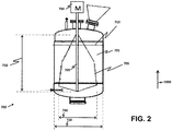
- FIG. 2 depicts a cross-sectional view of a hydrothermal reactor 700 with a blade 706 . Since the hydrothermal reactor 700 stands upright during operation, a vertical direction 1000 is first defined.
- positional modifiers such as "upper,” “lower,” “higher,” “uppermost,” “lowest,” etc., are interpreted with reference to the vertical direction 1000 .
- the hydrothermal reactor 700 has an internal cavity 701 .
- the internal cavity 701 is designed to have a highest liquid surface 710 allowed for depositing a reaction solution in the hydrothermal reactor 700 .
- the hydrothermal reactor 700 includes the blade 706 functioned as a stirrer for stirring the reaction solution and raw materials therein.
- the blade 706 is mounted to a shaft 705 .
- the shaft 705 is rotatable and is driven by a motor 704 such that the blade 706 is driven to stir the reaction solution and the raw materials.
- the blade 706 has a lateral span 740 (viz., a horizontal span) and a longitudinal length 730 (viz., a vertical height).
- the internal cavity 701 has a cross-sectional diameter 720 .
- the lateral span 740 is selected to be at least one third of the cross-sectional diameter 720 for reducing adhesion of any solid reaction product on a surface of the internal cavity 701 .
- the longitudinal length 730 is selected to cause the blade 706 to extend beyond, i.e. to rise above, the highest liquid surface 710 .
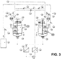
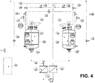
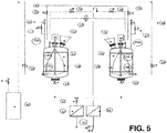
- FIGS. 3-6 Examples of practical implementation of the disclosed system are shown in FIGS. 3-6 .
- Each of the systems shown in FIGS. 3-6 is a two-reactor subcritical-water reaction system.
- the following numerals are used in FIGS. 3-6 and explanations of these numerals are provided.
- the lower extraction port 13 of the subcritical water reaction vessel 11 is closed and various kinds of raw materials and reaction additives are charged from the upper charging inlet 12 in various forms such as liquid state, solid state, semi-solid state, gel state, etc.
- Water for the reaction is also added from the water supply line 41 via valve 15 .
- the reaction vessel is stirred uniformly by the stirring blade 16 . Thereafter, steam is blown directly from the heat source 42 via the valve 14 , whereby the subcritical reaction vessel 11 is heated.
- the raw materials are charged into the subcritical reaction vessel 21 where the next reaction is carried out.
- Various kinds of materials and reaction additives are charged in various forms, such as liquid state, solid state, semi-solid state, gel state, etc., from the upper inlet port 22 while the lower outlet 23 of the reaction vessel 21 is closed.
- the high-temperature high-pressure reaction solution which has completed the hydrolysis reaction in the subcritical reaction vessel 11 after a predetermined time duration has passed, flows through the valve 13 and the valve 31 to the filtration equipment 32 .
- Self-circulation of the mixture of the superheated reaction solution and the solid reaction products is performed via the liquid transfer pump 33 , the filtration facility 34 and the valve 35 .
- the reaction products are separated and recovered in the filtration facilities 32 and 34 without leaving them in the reaction vessel.
- the valve 35 is closed and the valve 36 is opened.
- the high-temperature high-pressure reaction solution is transferred to the next subcritical reaction vessel 21 in which the valve 23 is closed.
- the reaction is then started in the reaction vessel 21 .
- the reaction solution is additionally heated by steam through opening the heating valve 24 .
- the reaction solution is additionally heated by opening the heating valve 29 .
- the substance produced by the reaction is separated and recovered at the filtration facilities 32 and 34 and then taken out of the reaction system.
- the lower outlet 13 of the subcritical water reactor 11 is closed, and from the upper inlet 12 various liquids, solids, semisolids, ingredients and reactive additives are charged in any kind the form.
- a hydrolysis reaction in the presence of the high-temperature high-pressure reaction solution is conducted at the target temperature. After a predetermined time duration elapses, the reaction in the subcritical reaction vessel 21 ends.
- the equalizing valve 37 is then opened.
- the superheated reaction solution passes through the valve 23 , the valve 31 , the filtration facility 32 and the liquid transfer pump 33.
- the reaction solution is then self-circulated via the filtration facility 34 and the valve 36 .
- the valve 36 is closed and the valve 35 is opened, whereby the reaction solution is transferred to the next reaction vessel, which is the subcritical water reactor 11 .
- the substances produced by the reaction i.e., the reaction products, are separated and recovered at the filtration facilities 32 and 34 .
- the valve 13 is closed.
- the reaction is then started, and the reaction solution is additionally heated by a heating valve 14 when necessary.
- a heating medium e.g., saturated steam
- the heating source 42 a boiler or a steam generator
- a large paddle blade 16 is installed, and a baffle is installed to improve the stirring efficiency.
- a pressure control system, a temperature control system, and a level control system are installed in the subcritical water reactor.
- the reaction of raw materials to be treated is monitored by a thermometer, a level meter, and a pressure gauge. The reaction time is also set.
- the subcritical water reactor 21 is substantially similar to the subcritical water reactor 11 in configuration.
- an automatic vent valve is provided together with a safety valve, but normally none of them operates unless there is special abnormality in the reaction vessel.
- the automatic vent valve operates to restore the preset pressure.
- the operation system control pressure of the reactor system should be smaller than the operation pressure of the automatic vent valve, which is also smaller than the pressure of the safety valve discharge pressure. Therefore, a slight sudden disturbance does not induce false triggering of the safety valve.
- each reactor is maintained at the working conditions (temperature, pressure, residence time) for obtaining the solid reaction products.
- the working temperature is between 110°C and 300°C
- the working pressure is between 0.12 to 8.7 MPa
- the residence time is in the range of 15 to 120 minutes.
- reaction vessels 11, 21 are equipped with respective coils 18, 28 for heating the reaction solution therein.
- Each of respective stirring blades 16, 26 in the reaction vessels 11, 21 is a large blade resembling the blade 706 as described above for FIG. 2 .
- the system of FIG. 5 is different from that of FIG. 6 in that the reaction vessels 11, 21 in the system of FIG. 5 are not equipped with any coil or jacket.
- a small blade smaller than the blade 760 is used in each of the reaction vessels 11, 21 . Furthermore, no coil or jacket is installed in each of the reaction vessels 11, 21 .
- the system of FIG. 3 employs the small blade in in each of the reaction vessels 11, 21 .
- the reaction vessels 11, 21 in the system of FIG. 3 are equipped with respective coils 18, 28 for heating the reaction solution therein.
- the disclosed semi-continuous hydrothermal reaction system can be used for processing organic wastes, clothes, fabrics, etc., composed of large solid matters that are difficult to be disposed of as target raw materials for subcritical water reaction treatment.
- Most of the clothing is in a state of blended fibers.
- these blended-fiber materials can be processed with heat treatment. It is possible to recycle old clothing by decomposing the old clothing to fibers and by separating the fiber raw materials from the reaction solution. It is possible to construct a plant with a small space, simple and at a low facility cost, as well as to obtain a product that can be operated at a low running cost.
Landscapes
- Chemical & Material Sciences (AREA)
- Organic Chemistry (AREA)
- Chemical Kinetics & Catalysis (AREA)
- Engineering & Computer Science (AREA)
- Oil, Petroleum & Natural Gas (AREA)
- Life Sciences & Earth Sciences (AREA)
- Physics & Mathematics (AREA)
- Thermal Sciences (AREA)
- Hydrology & Water Resources (AREA)
- Environmental & Geological Engineering (AREA)
- Water Supply & Treatment (AREA)
- General Chemical & Material Sciences (AREA)
- Wood Science & Technology (AREA)
- Combustion & Propulsion (AREA)
- Processing Of Solid Wastes (AREA)
- Physical Or Chemical Processes And Apparatus (AREA)
Description
- The present disclosure generally relates to a hydrothermal reaction system. In particular, the present disclosure relates to such hydrothermal system capable of achieving high efficiencies in both substance utilization and energy consumption.
- Recently, environmental issues have received much attention in textile and clothing industries. Physical reuse and chemical recycling of clothing and fabrics have been researched. Attention has been drawn to chemical decomposition and recycling of garments, fabrics, fibers and the like by means of subcritical water.
- However, most of the garments, fabrics, etc. are bulky solids that can be difficult to convert into a slurry, which is required for optimal treatment efficiency. Besides, these bulky solids are difficult to feed into the reactor in large quantities, decomposed at a stable rate, and extracted from the reactor in large quantities. An efficient subcritical water treatment plant for treating solid matters has been lacking in general.
- A batch-wise subcritical water treatment reactor that is commonly used is required to feed raw solid materials, reaction additives and reaction water on the top, and to extract reaction product materials at the bottom. Therefore, the reaction water used has to be discharged and discarded for each batch.
- As the reaction liquid is required to be discharged every time in a batch-type reactor, it is necessary to heat a new amount of reaction water every time, and to install a chilling device to cool down the hot reaction solution to be discharged, resulting in unnecessary energy consumption, extra running cost, as well as complicating the reactor design and leading to a huge size of equipment. Such drawbacks are major hindrances for the batch-type reactor to achieve competitiveness.
- Regardless of whether the reactor is a batch-type one or a continuous-type one, solid materials and reaction products may undesirably attach to the reaction vessel after reaction. Agglutination is formed on the inner surface of the reaction vessel, which may interfere with subsequent reaction(s). Therefore, it is necessary to discharge the retained solids from the reactor during the course of reaction. Not only does it interrupt the reaction process, but also requires even more complicated equipment design and an increased construction cost. The temperature, pressure, reaction additive concentration, and residence time in the reaction vessel are fluctuated, thus inevitably affecting the reaction rate and the resultant product quality.
- In the art, it is known how to treat organic matter under subcritical water conditions. A review of using subcritical (and supercritical) water for treating organic matters is given by Lachos-Perez, D., Brown, A.B., Mudhoo, A., Martinez, J., Timko, M.T., Rostagno, M.A., and Forster-Carneiro, T., "Subcritical and supercritical water extraction, hydrolysis, gasification and carbonization of biomass: a critical review," Biofuel Research Journal 14 (2017) 611-626, DOI: 10.18331/BRJ2017.4.2.6.
Japanese Patent No. 4334857 Japanese Unexamined Patent Application Publication No. 2001-137006 Japanese Patent No. 3963124 Japanese Unexamined Patent Publication No. 2013-14737 - A continuous reaction processing apparatus using subcritical water or supercritical water is described in
Japanese Unexamined Patent Publications No. 2001-347300 2004-298692 2008-296192 - It is also known in the art how to treat fibers under subcritical-water conditions. However, most of the total waste discharge of fibrous products is not recycled, and most of the waste discharge is incinerated. In particular, for cellulose such as cotton fibers, which account for about half of the whole textile/garment products containing a plurality of fibers like polyester (PET), most of waste discharge is incinerated due to difficulty in separating cotton fibers and PET fibers. In addition, it takes a lot of energy to incinerate mixed fibers, and it discharges carbon dioxide, a greenhouse gas. Therefore, there is a problem of high environmental burden, as reported in "The recycling technique of disposable clothing and the outline of development of high value added products," (translation), authored by Ministry of Economy, Trade and Industry, Manufacturing Industry Bureau Textile Division, Asahi Kasei Fibers Corporation, published 19 November 2009.
- In order to solve the aforementioned problem of high environmental burden, separation of the cotton fibers from the mixed fibers by a treatment method using subcritical water has been attempted. However, similar to the incineration approach, there is a problem that the environmental load is high, because it requires a lot of energy as reported in
Japanese Patent Application No. 2000-255554 - Most of the clothing that has been put to practical use is composed of mixed fibers. In separating these mixed fibers, there are only a few methods having high energy efficiency and economic viability. As one method for separating these mixed fibers, a technique of decomposing and recovering fibers by subcritical-water reaction treatment in the presence of an organic acid as a catalyst has been reported in
Japanese Patent Application No. 2017-156921 - Nonetheless, there is a need in the art for a subcritical water treatment system that can process bulky solid raw materials with one or more advantages such as improved energy efficiency, reduced equipment cost, reduced demand in space, discharge of the retained solids from the reactor without affecting the reaction rate and resultant product quality, etc. Since a subcritical water reactor is one type of hydrothermal reactor, the approach used in developing the subcritical water treatment system is applicable to developing a hydrothermal reaction system.
- The present disclosure provides a hydrothermal reaction system for processing batches of raw materials in a semi-continuous manner. The system comprises a plurality of hydrothermal reactors, a filtering subsystem, a fluid subsystem and a computer control subsystem.
- An individual hydrothermal reactor is configured to pressurize and heat a reaction solution to reach a target pressure and a target temperature so as to form a superheated reaction solution. The superheated reaction solution is used for reacting with a batch of raw materials deposited in the individual hydrothermal reactor to yield a plurality of solid reaction products.
- The filtering subsystem comprises one or more filters for separating the plurality of solid reaction products from the superheated reaction solution. Thereby, the superheated reaction solution is recovered.
- The fluid subsystem comprises one or more pipes, one or more valves and one or more pumps for carrying a liquid to and from the filtering subsystem and to and from the individual hydrothermal reactor. The liquid is the superheated reaction solution or a mixture of the superheated reaction solution and the plurality of solid reaction products.
- The computer control subsystem comprises one or more computers for controlling the plurality of hydrothermal reactors and the fluid subsystem. The one or more computers are arranged and programmed to configure the fluid subsystem to transfer the recovered superheated reaction solution previously used for reacting with a first batch of raw materials deposited in a first hydrothermal reactor to a second hydrothermal reactor different from the first hydrothermal reactor for recycling the superheated reaction solution in reacting with a second batch of raw materials. The first and second hydrothermal reactors are selected from the plurality of hydrothermal reactors. The one or more computers are further arranged and programmed to configure the second hydrothermal reactor to receive the second batch of raw materials under atmospheric pressure before the superheated reaction solution used in reacting with the first batch of raw materials is recovered by the filtering subsystem. Thereby, the disclosed system processes different batches of raw materials in a semi-continuous manner.
- In one non-limiting option, the individual hydrothermal reactor is a subcritical water reactor configured to pressurize and heat the reaction solution comprising water to form the superheated reaction solution comprising subcritical water. In certain embodiments, the plurality of hydrothermal reactors consists of two subcritical water reactors.
- In another non-limiting option, the individual hydrothermal reactor is a supercritical water reactor such that the superheated reaction solution formed from the reaction solution that comprises water includes supercritical water. In certain embodiments, the plurality of hydrothermal reactors consists of two supercritical water reactors.
- The one or more computers may be further arranged and programmed to configure the second hydrothermal reactor to receive reaction additives under atmospheric pressure before the superheated reaction solution used in reacting with the first batch of raw materials is recovered by the filtering system.
- The one or more computers may also be further arranged and programmed to configure the one or more valves and the one or more pumps to set up a circuit in a network formed by the one or more pipes. The circuit is used for circulating the mixture between the filtering subsystem and the individual hydrothermal reactor so as to collect the plurality of solid reaction products at the filtering subsystem.
- Preferably, the individual hydrothermal reactor comprises a stirrer for stirring the superheated reaction solution in the individual hydrothermal reactor. The stirrer may be a paddle blade or a turbine blade. In certain embodiments, the stirrer is a blade having a lateral span and a longitudinal length satisfying the following requirements. First, the lateral span occupies at least one third of a cross-sectional diameter of an internal cavity of the individual hydrothermal reactor for reducing adhesion of any solid reaction product on a surface of the internal cavity. Second, the longitudinal length that is selected causes the blade to extend beyond a highest liquid surface allowed for the individual hydrothermal reactor.
- In certain embodiments, the individual hydrothermal reactor is configured to heat the reaction solution to reach the target temperature that is in a range of 105°C and 370°C. In certain embodiments, the individual hydrothermal reactor is configured to heat the reaction solution to reach the target temperature selected over at least a range of 105°C and 150°C.
- In certain embodiments, the individual hydrothermal reactor is further configured to blow superheated steam or saturated steam into an internal cavity of the individual hydrothermal reactor for heating the reaction solution.
- In certain embodiments, the individual hydrothermal reactor comprises a coil located at a periphery of the individual hydrothermal reactor. The coil is configured to carry a heating medium for heating the reaction solution. The heating medium may be superheated steam or saturated steam.
- In certain embodiments, the individual hydrothermal reactor comprises a jacket located at a periphery of the individual hydrothermal reactor. The jacket is configured to intake a heating medium for heating the reaction solution. The heating medium may be superheated steam or saturated steam.
- Other aspects of the present disclosure are disclosed as illustrated by the embodiments hereinafter.
-
-
FIG. 1 depicts a hydrothermal reaction system in accordance with an exemplary embodiment of the present disclosure. -
FIG. 2 depicts a cross-sectional view of a hydrothermal reaction system to show a stirring blade therein in accordance of one embodiment of the present disclosure. -
FIG. 3 depicts a first realization of the disclosed hydrothermal reaction in accordance with one embodiment of the present disclosure. -
FIG. 4 depicts a second realization of the disclosed hydrothermal reaction in accordance with one embodiment of the present disclosure. -
FIG. 5 depicts a third realization of the disclosed hydrothermal reaction in accordance with one embodiment of the present disclosure. -
FIG. 6 depicts a fourth realization of the disclosed hydrothermal reaction in accordance with one embodiment of the present disclosure. - A hydrothermal reactor is a reaction vessel configured to heat and pressurize a reaction solution that contains aqueous solutions and mixtures thereof to a certain temperature and a certain pressure so as to allow a reaction, e.g., hydrolysis, to carry out with one or more reactants deposited in the reaction vessel. The hydrothermal reactor may be specifically configured for setting the pressure and temperature to form subcritical water in the reaction solution so as to conduct the reaction in the presence of subcritical water. This special configuration of the hydrothermal reactor is referred to as a subcritical water reactor. As used throughout the specification and appended claims, the subcritical water reactor is understood to be one type of hydrothermal reactor. Similarly, a supercritical water reactor is configured to form supercritical water in the reaction solution for carrying out reaction, and is understood to be another type of hydrothermal reactor.
- Before details of the hydrothermal reaction system disclosed herein are provided, a description of how the disclosed system operates is given as follows. Raw materials in the form of bulky solids are added to a reaction vessel (i.e. a hydrothermal reactor) of the disclosed system. The raw materials, such as organic waste (biomass), clothing, fibers, fabrics and cloth, are intended for hydrothermal treatment. Reaction additives, such as water and acid(s), are also added to the reaction vessel to form a reaction solution. The addition of the raw materials and the reaction additives is conveniently carried out under atmospheric pressure. The reaction vessel is then heated to keep the temperature and pressure of the reaction solution constant over time. As a result, steady reaction is carried out to decompose the raw materials. By transferring the reaction solution directly to a second reaction vessel without cooling so as to reuse the reaction solution for another round of reaction, a high efficiency in substance and energy utilization is achieved. The second reaction vessel has already been deposited with another batch of raw materials and possibly with some reaction additives to compensate for some loss of reaction solution and/or reactants spent in previous reaction. As such, the disclosed system is equipped with two reaction vessels. Reactions are performed alternately in the two reaction vessels. While reaction in one reaction vessel is in progress, another reaction vessel is available for deposition of raw materials and reaction additives under atmospheric pressure. The disclosed system operates in a semi-continuous manner in that it is feasible to initiate processing a new batch of raw materials shortly after one batch of raw materials is completed in processing. By this semi-continuous processing of different batches of raw materials, stable reaction is achievable. Discharging the high-temperature reaction solution is eliminated, and cooling of the reaction solution is not required. As a result, miniaturization of the system and reduction of energy cost are realized. It is also possible that the disclosed system is equipped with more-than-two reaction vessels, though having only two reaction vessels is most advantageous in the sense of minimizing the equipment cost and the space requirement.
- An aspect of the present disclosure is to provide a hydrothermal reaction system for processing batches of raw materials in a semi-continuous manner.
-
FIG. 1 depicts an exemplary realization of the disclosed system. Asystem 200 comprises a plurality ofhydrothermal reactors 211a-c, afiltering subsystem 220, afluid subsystem 230 and acomputer control subsystem 240. - Although three
hydrothermal reactors 211a-c are depicted inFIG. 1 for illustration, the present invention is not limited to this number of reactors; in the present invention, there are at least two hydrothermal reactors. Nevertheless, it is a preferable choice to have only two hydrothermal reactors in thesystem 200 due to the advantages mentioned above. - An individual hydrothermal reactor (also referenced as 211a-c) is configured to pressurize and heat a reaction solution to reach a target pressure and a target temperature for forming a superheated reaction solution. Since a hydrothermal reaction is conducted, the reaction solution comprises water. The superheated reaction solution is used for reacting with a batch of raw materials deposited in the individual
hydrothermal reactor 211a-c to thereby yield a plurality of solid reaction products. For example, if the raw materials are garments made of cotton and PET, and if the reaction solution contains water, the garments are hydrolyzed and decomposed into cotton fibers and PET fibers. These cotton fibers and PET fibers are in fiber form or in powder form. In this example, the plurality of solid reaction products includes the cotton fibers and the PET fibers. In case all the garments are not completely hydrolyzed, the plurality of solid reaction products further includes garment fragments that have not been broken down into fibers. - Preferably, the individual
hydrothermal reactor 211a-c is configured to pressurize the reaction solution by heating the reaction solution while keeping the first reactor as a closed vessel sealed off from the atmosphere. In this configuration of the individualhydrothermal reactor 211a-c, the pressure inside the closed vessel is the vapor pressure of the water. The target pressure is therefore related to the target temperature, and is the vapor pressure of the water at the target temperature. Nonetheless, pressurization of the reaction solution is not restricted to using the aforementioned method. Pressurization of the reaction solution may also be done by blowing heated steam into the vessel. Excess steam that gives rise to overpressure may be released out of the individualhydrothermal reactor 211a-c by venting via a pressure control valve, thereby setting the target pressure to be the vapor pressure of the water at the target temperature. - In one embodiment, the individual
hydrothermal reactor 211a-c is a subcritical water reactor. The subcritical water reactor is configured to pressurize and heat the reaction solution comprising water to form the superheated reaction solution comprising subcritical water. Note that the target pressure and target temperature are selected such that subcritical water is formed from water under the selected target pressure and the selected target temperature. - One intended use of the disclosed system is to process raw materials that are bulky solid matters incapable of slurring or dissolution in subcritical water reaction. To treat bulky solid objects, such as garments, one may use the system with reaction additives such as water, acid(s), alkali(s), inorganic compound(s), organic compound(s) and/or catalyst(s). The reaction temperature (viz., the target temperature) may be selected to be between 105°C and 370°C, and the reaction pressure (viz., the target pressure) may be chosen to be between 0.12 MPa and 21 MPa.
- A particularly advantageous use of the disclosed system is to process garments, clothes, fabrics, textile materials, etc., as raw materials for subcritical water reaction. In this processing, preferably the reaction solution contains one or more organic acids for speeding up chemical decomposition of the raw materials by hydrolysis. According to one study conducted by the Inventors, the reaction additives and various process parameters are given as follows. An individual organic acid may be selected from citric acid, oxalic acid, tartaric acid, maleic acid and acetic acid. The one or more organic acids can be present at a concentration of between 1-25 % (w/w) in reaction solution. In certain embodiments, the one or more organic acids can be present at a concentration of between 3-20, 3-19, 3-18, 3-17, 3-16, 5-15, 7-15, or 10-15 % (w/w). The target temperature is preferable to be between 100°C and 150°C inclusively. As the target pressure may be determined as the vapor pressure of water at the target temperature, preferably the target pressure is between 0.12 MPa to 0.50 MPa. Correspondingly, the individual
hydrothermal reactor 211a-c is configured to heat the reaction solution to reach the target temperature selected over at least a range of 105°C and 150°C. The target temperature may be set according to the type of fibers intended to be recovered from the raw materials. Advantageously, even when the target temperature is selected to be higher than 100°C, fibers of polyester, polypropylene, lycra and acrylic contained in the raw materials can maintain their fiber shape in the plurality of solid reaction products. With the target temperature set at 110°C or lower, cotton and rayon contained in the raw materials are melted and/or decomposed to fine powders in the plurality of solid reaction products. With the target temperature set at 115°C or higher, cotton, wool, nylon, rayon and cupra contained in the raw materials are melted and/or decomposed to fine powders in the plurality of solid reaction products. With the target temperature set to 125°C or higher, cotton, wool, nylon, silk, rayon, cupra and acetate contained in the raw materials are melted and/or decomposed to fine powders in the plurality of solid reaction products. - In another embodiment, the individual hydrothermal reactor is 211a-c is a supercritical water reactor. The supercritical water reactor is configured to support working ranges of the target temperature and the target pressure such that the water content into the reaction solution is heated and pressurized to form supercritical water in the superheated reaction solution.
- The
filtering subsystem 220 comprises one ormore filters 221a-b. Thefiltering subsystem 220 is used for separating the plurality of solid reaction products from the superheated reaction solution by filtering. Although twofilters 221a-b are shown inFIG. 2 for illustration, the present invention is not limited to this number of filters in realizing the one ormore filters 221a-b. The one ormore filters 221a-b may be implemented as a multistage filter. In one embodiment, the one ormore filters 221a-b may include a serial cascade of a first-stage filter 221a and a second-stage filter 221b. The first- and second-stage filters 221a-b may be configured such that the first-stage filter 221a filters out larger solid reaction products and the second-stage filter 221b filters out smaller solid reaction products. - The
fluid subsystem 230 is used for carrying a liquid to and from thefiltering subsystem 220 and to and from the individualhydrothermal reactor 211a-c. The liquid is the superheated reaction solution or a mixture of the superheated reaction solution and the plurality of solid reaction products. In particular, thefluid subsystem 230 comprises: one ormore pipes 231a-d connectable to thefiltering subsystem 220 and the individualhydrothermal reactor 211a-c for carrying the liquid; one ormore valves 233a-i for dynamically establishing one or more routes in a network formed by the one ormore pipes 231a-d; and one ormore pumps 235a-b for pumping the liquid through an individual route. Although fourpipes 231a-d, ninevalves 233a-i and twopumps 235a-b are shown inFIG. 1 for illustration, the present invention is not limited to these numbers in respectively realizing the one ormore pipes 231a-d, the one ormore valves 233a-i and the one ormore pumps 235a-b. An example of a route is a cascade of thepipes valves valves reactor 211a and an input of the first-stage filter 221a. Thepump 235a is used to drive the liquid from thereactor 211a to the first-stage filer 221a. - The
computer control subsystem 240 is used for determining the one or more routes and also used for controlling the plurality ofhydrothermal reactors 211a-c and thefluid subsystem 230. Thecomputer control subsystem 240 comprises one ormore computers 241a-b. Although twocomputers 241a-b are shown inFIG. 1 for illustration, the present disclosure is not limited to this number in realizing the one ormore computers 241a-b. - To achieve the advantage of reusing the superheated reaction solution, the one or
more computers 241a-b are arranged and programmed to configure thefluid subsystem 230 to transfer the recovered superheated reaction solution previously used for reacting with one a first batch of the raw materials deposited in a first hydrothermal reactor (e.g., thereactor 211a) to a second hydrothermal reactor (e.g., thereactor 211b) different from the first hydrothermal reactor for recycling the superheated reaction solution in reacting with a second batch of raw materials. Note that the first and second hydrothermal reactors are selected from the plurality ofhydrothermal reactors 211a-c. - As one example, it is desired to transfer the recovered superheated reaction solution from the
first reactor 211a to thesecond reactor 211b, where the recovered superheated reaction solution has been returned back to thefirst reactor 211a after filtering by thefiltering subsystem 220 is done. The one ormore computers 241a-b determine that the recovered superheated reaction solution passes a route formed by thepipes more computers 241a-b configure thevalves valves pump 235a to switch on, and thepump 235b to switch off. - As another example, it is desired to transfer the recovered superheated reaction solution, obtained immediately after filtering the mixture stored in the
first reactor 211a, directly from an output of thefiltering subsystem 220 to thesecond reactor 211b. The one ormore computers 241a-b determine to set up a first route formed by thepipes first reactor 211a to thefiltering subsystem 220, and a second route formed by thepipes filtering subsystem 220 to thesecond reactor 211b. The one ormore computers 241a-b configure thevalves valves pumps 235a-b to switch on. - To achieve semi-continuous processing for batches of raw materials, the one or
more computers 241a-b are further arranged and programmed to configure the second hydrothermal reactor to receive the second batch of raw materials under atmospheric pressure before the superheated reaction solution used in reacting with the first batch of raw materials is recovered by thefiltering subsystem 220. As mentioned above, the first and second hydrothermal reactors are different. It follows that while the first batch of raw materials is undergoing reaction in the first hydrothermal reactor, the second batch of raw materials is conveniently deposited into the second hydrothermal reactor under atmospheric pressure. Preferably and advantageously, the one ormore computers 241a-b are further arranged and programmed to configure the second hydrothermal reactor to receive reaction additives under atmospheric pressure before the superheated reaction solution used in reacting with the first batch of raw materials is recovered by the filtering system - As an example, consider that the
reactors reactor 211a is pressurized and heated to conduct hydrothermal reaction on the first batch of raw materials, thereactor 211b is deposited with the second batch of raw materials together with depositing the reaction additives therein under atmospheric pressure. After the reaction conducted in thereactor 211a is completed and the superheated reaction solution is recovered by thefiltering subsystem 220, the superheated reaction solution is transferred to thereactor 211b such that reaction on the second batch of raw materials can be conducted thereafter. - In one option, the one or
more computers 241a-b are further arranged and programmed to organize the one or more routes as a circuit for circulating the mixture between thefiltering subsystem 220 and the individualhydrothermal reactor 211a-c so as to carry out plural rounds of filtering to more thoroughly filter out the plurality of solid reaction products from the mixture. As an example for illustration, it is desired to set up a (closed-loop) circuit to circulate the mixture between thefiltering subsystem 220 and thereactor 211a. A first route formed by thepipes reactor 211a to an input port of thefiltering subsystem 220. A second route formed by thepipes reactor 211a. The two routes are set up by opening thevalves valves pumps 235a-b are activated to circulate the mixture between thereactor 211a and thefiltering subsystem 220 through the circuit. - In realizing the
system 200, an individual computer (referenced as 241a-b) in thecomputer control subsystem 240 may be located close to the plurality ofhydrothermal reactors 211a-c and thefiltering subsystem 220 such that thesystem 200 is compactly formed to reduce the space requirement. Alternatively, theindividual computer 241a-b may be remotely located from the plurality ofhydrothermal reactors 211a-c and thefiltering subsystem 220, and remotely control the same via a communication network, wired or wireless. - Further aspects regarding the individual
hydrothermal reactor 211a-c are disclosed as follows. - Usually, the individual
hydrothermal reactor 211a-c includes one or more addition valves for accepting the reaction additives and the batch of raw materials. - In typical subcritical water reactors, handling of raw materials is restricted, and it usually keeps the solid particle diameter to be not more than 1 mm so that slurry can be formed. In the disclosed system, however, the solid raw materials may be crushed in pretreatment before added to the individual
hydrothermal reactor 211a-c as necessary, or may be added as they are. There is no size restriction for solid raw materials. - The phenomenon of damaging the reaction rate and product quality such as agglutinate in the individual
hydrothermal reactor 211a-c is often caused by local heating and stagnant plaque. In order to eliminate local overheating, it is desirable to reduce the temperature difference between a heating source and an internal cavity of the individualhydrothermal reactor 211a-c as much as possible. - From the above point of view, in order to achieve high energy efficiency for heating reactor, it is desirable to directly blow overheated steam and/or saturated steam produced by a boiler or a steam generator into the individual
hydrothermal reactor 211a-c. Preferably, the individualhydrothermal reactor 211a-c comprises a heater (e.g., aheating source 42 shown inFIG. 6 ), such as the boiler and the steam generator, and is further configured to blow superheated steam or saturated steam into the internal cavity of the individualhydrothermal reactor 211a-c for heating the reaction solution. The individualhydrothermal reactor 211a-c usually includes a blowing port through which the superheated steam or saturated steam is blown into the internal cavity. It is also desirable to install a silencer at the blowing port to reduce noise caused by steam blowing and to prevent, or reduce, leakage of heated steam into the atmosphere. - Direct blowing of steam causes condensation of the blowing steam in the individual
hydrothermal reactor 211a-c, and introduces difficulty in maintaining a constant amount of the reaction solution in the internal cavity. To deal with this issue, the individualhydrothermal reactor 211a-c may further include a sensor for measuring the amount of the reaction solution or a height thereof in the internal cavity. Based on the measured amount or height, the one ormore computers 241a-b may control the volume of the reaction solution by configuring the individualhydrothermal reactor 211a-c to withdraw a portion of high-temperature reaction solution or to add some reaction additives (which include water) from outside the individualhydrothermal reactor 211a-c. - In general, when it is necessary to drastically heat the reaction solution from a low temperature to the target temperature, direct injection of steam is carried out. When a steady temperature is reached, drastic heating is not necessary. Heating the reaction solution by a less energy-consuming approach is more desirable. For this purpose, preferably the individual
hydrothermal reactor 211a-c further includes a coil or a jacket for heating the reaction solution. Both the coil and the jacket are located at a periphery of the individualhydrothermal reactor 211a-c. The coil forms a tube encircling the individualhydrothermal reactor 211a-c. The jacket wraps the individualhydrothermal reactor 211a-c. The coil and the jacket are configured to carry a heating medium for heating the reaction solution. Generally, the heating medium is superheated steam or saturated steam. - Furthermore, increasing the stirring effect is also an important issue to maintain a stable reaction rate. Preferably, the individual
hydrothermal reactor 211a-c further includes a stirrer for stirring the superheated reaction solution therein. - There are many common types of the stirrer such as a paddle blade, a turbine blade, a propeller blade, an anchor blade, a ribbon blade, a small-blade-diameter paddle blade, a pitch paddle blade, a double pitch paddle blade, an edged turbine blade, a pitched turbine blade, a disk turbine blade, a radial flow turbine blade, an axial flow turbine blade, a pincushion type blade, etc. Nevertheless, not all blades are optimal in stirring large solids, fibers, clothing and string-like fiber masses in that these solid materials may stick on surfaces of shafts and blades.
- In order to avoid, or at least to reduce the possibility of, adhesion and retention on the surfaces of shafts and blades, the stirrer is preferred to be a large blade in comparison with the internal cavity of the individual
hydrothermal reactor 211a-c. One embodiment of such large blade is illustrated inFIG. 2 , which depicts a cross-sectional view of ahydrothermal reactor 700 with ablade 706. Since thehydrothermal reactor 700 stands upright during operation, avertical direction 1000 is first defined. Herein in the specification and appended claims, positional modifiers, such as "upper," "lower," "higher," "uppermost," "lowest," etc., are interpreted with reference to thevertical direction 1000. It is also used herein that "longitudinal" is a modifier indicating a direction parallel to thevertical direction 1000, and that "lateral" is another modifier indicating a direction perpendicular to thevertical direction 1000. Thehydrothermal reactor 700 has aninternal cavity 701. Theinternal cavity 701 is designed to have ahighest liquid surface 710 allowed for depositing a reaction solution in thehydrothermal reactor 700. Thehydrothermal reactor 700 includes theblade 706 functioned as a stirrer for stirring the reaction solution and raw materials therein. Theblade 706 is mounted to ashaft 705. Theshaft 705 is rotatable and is driven by amotor 704 such that theblade 706 is driven to stir the reaction solution and the raw materials. Theblade 706 has a lateral span 740 (viz., a horizontal span) and a longitudinal length 730 (viz., a vertical height). Theinternal cavity 701 has across-sectional diameter 720. Thelateral span 740 is selected to be at least one third of thecross-sectional diameter 720 for reducing adhesion of any solid reaction product on a surface of theinternal cavity 701. Thelongitudinal length 730 is selected to cause theblade 706 to extend beyond, i.e. to rise above, thehighest liquid surface 710. - Examples of practical implementation of the disclosed system are shown in
FIGS. 3-6 . Each of the systems shown inFIGS. 3-6 is a two-reactor subcritical-water reaction system. The following numerals are used inFIGS. 3-6 and explanations of these numerals are provided. - 11, 21: Subcritical water reactor.
- 12, 22: Upper inlet.
- 13, 23: Lower outlet.
- 14, 19, 24, 29: Heating valve.
- 18, 28: Coil / Jacket.
- 15, 17, 25, 27, 31, 35, 36, 37: Valve.
- 16, 26: Stirring blade.
- 32, 34: Filtration equipment.
- 33: Transfer pump.
- 41: Water supply line.
- 42: Heat source equipment.
- 43, 44: Vent line.
- Explanation of practical implementation aspects of the disclosed system is made with reference to the system depicted in
FIG. 6 . - The
lower extraction port 13 of the subcriticalwater reaction vessel 11 is closed and various kinds of raw materials and reaction additives are charged from theupper charging inlet 12 in various forms such as liquid state, solid state, semi-solid state, gel state, etc. Water for the reaction is also added from thewater supply line 41 viavalve 15. The reaction vessel is stirred uniformly by the stirringblade 16. Thereafter, steam is blown directly from theheat source 42 via thevalve 14, whereby thesubcritical reaction vessel 11 is heated. - When heating is started in the subcritical
water reaction vessel 11, the raw materials are charged into the subcritical reaction vessel 21 where the next reaction is carried out. Various kinds of materials and reaction additives are charged in various forms, such as liquid state, solid state, semi-solid state, gel state, etc., from theupper inlet port 22 while thelower outlet 23 of the reaction vessel 21 is closed. - With the equalizing
valve 37 open, the high-temperature high-pressure reaction solution, which has completed the hydrolysis reaction in thesubcritical reaction vessel 11 after a predetermined time duration has passed, flows through thevalve 13 and thevalve 31 to thefiltration equipment 32. Self-circulation of the mixture of the superheated reaction solution and the solid reaction products is performed via theliquid transfer pump 33, thefiltration facility 34 and thevalve 35. The reaction products are separated and recovered in thefiltration facilities valve 35 is closed and thevalve 36 is opened. The high-temperature high-pressure reaction solution is transferred to the next subcritical reaction vessel 21 in which thevalve 23 is closed. The reaction is then started in the reaction vessel 21. When the temperature difference between the target temperature and the actual temperature of the reaction solution is large, the reaction solution is additionally heated by steam through opening the heating valve 24. When the temperature difference is small, the reaction solution is additionally heated by opening theheating valve 29. The substance produced by the reaction is separated and recovered at thefiltration facilities - In the subcritical water reactor 21, when the heating is started, the
lower outlet 13 of thesubcritical water reactor 11 is closed, and from theupper inlet 12 various liquids, solids, semisolids, ingredients and reactive additives are charged in any kind the form. - A hydrolysis reaction in the presence of the high-temperature high-pressure reaction solution is conducted at the target temperature. After a predetermined time duration elapses, the reaction in the subcritical reaction vessel 21 ends. The equalizing
valve 37 is then opened. The superheated reaction solution passes through thevalve 23, thevalve 31, thefiltration facility 32 and theliquid transfer pump 33. The reaction solution is then self-circulated via thefiltration facility 34 and thevalve 36. When the self-circulation is completed, thevalve 36 is closed and thevalve 35 is opened, whereby the reaction solution is transferred to the next reaction vessel, which is thesubcritical water reactor 11. The substances produced by the reaction, i.e., the reaction products, are separated and recovered at thefiltration facilities subcritical reaction vessel 11, thevalve 13 is closed. The reaction is then started, and the reaction solution is additionally heated by aheating valve 14 when necessary. - By alternately transferring the reaction solution between the two subcritical water reactors in the aforementioned manner, it is possible to transfer the high-temperature high-pressure reaction solution directly to the next vessel without discharging or cooling the reaction solution, as well as to achieve a high energy efficiency. Thus, it realizes miniaturization of equipment and reduction of operating cost.
- On the body side of the subcritical
water reaction vessel 11, a heating medium (e.g., saturated steam) is supplied by the heating source 42 (a boiler or a steam generator) via the heatingmedium supply valve 14. Inside thesubcritical water reactor 11, alarge paddle blade 16 is installed, and a baffle is installed to improve the stirring efficiency. Besides, a pressure control system, a temperature control system, and a level control system are installed in the subcritical water reactor. The reaction of raw materials to be treated is monitored by a thermometer, a level meter, and a pressure gauge. The reaction time is also set. The subcritical water reactor 21 is substantially similar to thesubcritical water reactor 11 in configuration. - In each of the subcritical
water reaction vessels 11, 21, an automatic vent valve is provided together with a safety valve, but normally none of them operates unless there is special abnormality in the reaction vessel. When the internal cavity of the reactor vessel exceeds the preset pressure (i.e. the target pressure), the automatic vent valve operates to restore the preset pressure. There is a relationship between the operation control pressure of the reactor system, the safety valve discharge pressure, and the automatic vent valve operation pressure: the operation system control pressure of the reactor system should be smaller than the operation pressure of the automatic vent valve, which is also smaller than the pressure of the safety valve discharge pressure. Therefore, a slight sudden disturbance does not induce false triggering of the safety valve. - When the reaction is needed to be paused, pause the corresponding subcritical water reactor while the reaction solution is kept in the reactor. The reactor is allowed to cool naturally. Thus, a special cooling device is not required.
- The internal cavity of each reactor is maintained at the working conditions (temperature, pressure, residence time) for obtaining the solid reaction products. Although there is no limitation on the working temperature, the working pressure and the residence time, practically the working temperature is between 110°C and 300°C, the working pressure is between 0.12 to 8.7 MPa, and the residence time is in the range of 15 to 120 minutes.
- The differences among the systems of
FIGS. 3-6 are in the subcriticalwater reaction vessels 11, 21. - In the system of
FIG. 6 , thereaction vessels 11, 21 are equipped withrespective coils respective stirring blades reaction vessels 11, 21 is a large blade resembling theblade 706 as described above forFIG. 2 . - The system of
FIG. 5 is different from that ofFIG. 6 in that thereaction vessels 11, 21 in the system ofFIG. 5 are not equipped with any coil or jacket. - In the system of
FIG. 4 , a small blade smaller than the blade 760 is used in each of thereaction vessels 11, 21. Furthermore, no coil or jacket is installed in each of thereaction vessels 11, 21. - Similar to the system of
FIG. 4 , the system ofFIG. 3 employs the small blade in in each of thereaction vessels 11, 21. Same as the system ofFIG. 6 , thereaction vessels 11, 21 in the system ofFIG. 3 are equipped withrespective coils - The present invention may be embodied in other specific forms without departing from the essential characteristics thereof. The present embodiment is therefore to be considered in all respects as illustrative and not restrictive. The scope of the invention is indicated by the appended claims rather than by the foregoing description, and all changes that come within the meaning and range of equivalency of the claims are therefore intended to be embraced therein.
- The disclosed semi-continuous hydrothermal reaction system can be used for processing organic wastes, clothes, fabrics, etc., composed of large solid matters that are difficult to be disposed of as target raw materials for subcritical water reaction treatment. Most of the clothing is in a state of blended fibers. In separating these blended fibers, there have been few methods that are able to achieve a high energy efficiency and an economic viability. With the disclosed system, these blended-fiber materials can be processed with heat treatment. It is possible to recycle old clothing by decomposing the old clothing to fibers and by separating the fiber raw materials from the reaction solution. It is possible to construct a plant with a small space, simple and at a low facility cost, as well as to obtain a product that can be operated at a low running cost.
Claims (15)
- A hydrothermal reaction system comprising:a plurality of hydrothermal reactors, wherein an individual hydrothermal reactor is configured to pressurize and heat a reaction solution to reach a target pressure and a target temperature so as to form a superheated reaction solution, the superheated reaction solution being used for reacting with a batch of raw materials deposited in the individual hydrothermal reactor to yield a plurality of solid reaction products;a filtering subsystem comprising one or more filters for separating the plurality of solid reaction products from the superheated reaction solution, whereby the superheated reaction solution is recovered;a fluid subsystem comprising one or more pipes, one or more valves and one or more pumps for carrying a liquid to and from the filtering subsystem and to and from the individual hydrothermal reactor, the liquid being the superheated reaction solution or a mixture of the superheated reaction solution and the plurality of solid reaction products;a computer control subsystem comprising one or more computers for controlling the plurality of hydrothermal reactors and the fluid subsystem, the one or more computers being arranged and programmed:to configure the fluid subsystem to transfer the recovered superheated reaction solution previously used for reacting with a first batch of raw materials deposited in a first hydrothermal reactor to a second hydrothermal reactor different from the first hydrothermal reactor for recycling the superheated reaction solution in reacting with a second batch of raw materials, wherein the first and second hydrothermal reactors are selected from the plurality of hydrothermal reactors; andto configure the second hydrothermal reactor to receive the second batch of raw materials under atmospheric pressure before the superheated reaction solution used in reacting with the first batch of raw materials is recovered by the filtering subsystem.
- The system of claim 1, wherein the individual hydrothermal reactor is a subcritical water reactor configured to pressurize and heat the reaction solution comprising water to form the superheated reaction solution comprising subcritical water.
- The system of claim 2, wherein the plurality of hydrothermal reactors consists of two subcritical water reactors.
- The system of any of claims 1-3, wherein the one or more computers are further arranged and programmed to configure the second hydrothermal reactor to receive reaction additives under atmospheric pressure before the superheated reaction solution used in reacting with the first batch of raw materials is recovered by the filtering system.
- The system of any of claims 1-3, wherein the one or more computers are further arranged and programmed to configure the one or more valves and the one or more pumps to set up a circuit in a network formed by the one or more pipes for circulating the mixture between the filtering subsystem and the individual hydrothermal reactor so as to collect the plurality of solid reaction products at the filtering subsystem.
- The system of any of claims 1-3, wherein the individual hydrothermal reactor comprises a stirrer for stirring the superheated reaction solution in the individual hydrothermal reactor.
- The system of claim 6, wherein the stirrer is a paddle blade or a turbine blade.
- The system of claim 6, wherein the stirrer is a blade having a lateral span and a longitudinal length such that:the lateral span is at least one third of a cross-sectional diameter of an internal cavity of the individual hydrothermal reactor for reducing adhesion of any solid reaction product on a surface of the internal cavity; andthe longitudinal length that is selected causes the blade to extend beyond a highest liquid surface allowed for the individual hydrothermal reactor.
- The system of any of claims 1-3, wherein the individual hydrothermal reactor is configured to heat the reaction solution to reach the target temperature that is within a range of 105°C to 370°C.
- The system of any of claims 1-3, wherein the individual hydrothermal reactor is configured to heat the reaction solution to reach the target temperature selected over at least a range of 105°C and 150°C.
- The system of any of claims 1-3, wherein the individual hydrothermal reactor is further configured to blow superheated steam or saturated steam into an internal cavity of the individual hydrothermal reactor for heating the reaction solution.
- The system of any of claim 1-3, wherein the individual hydrothermal reactor comprises a coil located at a periphery of the individual hydrothermal reactor, the coil being configured to carry a heating medium for heating the reaction solution.
- The system of claim 12, wherein the heating medium is superheated steam or saturated steam.
- The system of any of claims 1-3, wherein the individual hydrothermal reactor comprises a jacket located at a periphery of the individual hydrothermal reactor, the jacket being configured to intake a heating medium for heating the reaction solution.
- The system of claim 14, wherein the heating medium is superheated steam or saturated steam.
Priority Applications (1)
| Application Number | Priority Date | Filing Date | Title |
|---|---|---|---|
| EP19181129.8A EP3753999B1 (en) | 2019-06-19 | 2019-06-19 | Semi-continous hydrothermal reaction system |
Applications Claiming Priority (1)
| Application Number | Priority Date | Filing Date | Title |
|---|---|---|---|
| EP19181129.8A EP3753999B1 (en) | 2019-06-19 | 2019-06-19 | Semi-continous hydrothermal reaction system |
Publications (2)
| Publication Number | Publication Date |
|---|---|
| EP3753999A1 EP3753999A1 (en) | 2020-12-23 |
| EP3753999B1 true EP3753999B1 (en) | 2021-11-03 |
Family
ID=66998277
Family Applications (1)
| Application Number | Title | Priority Date | Filing Date |
|---|---|---|---|
| EP19181129.8A Active EP3753999B1 (en) | 2019-06-19 | 2019-06-19 | Semi-continous hydrothermal reaction system |
Country Status (1)
| Country | Link |
|---|---|
| EP (1) | EP3753999B1 (en) |
Family Cites Families (11)
| Publication number | Priority date | Publication date | Assignee | Title |
|---|---|---|---|---|
| JP2000255554A (en) | 1999-03-08 | 2000-09-19 | Hitachimori Shigyo Kk | Assembled box for packaging |
| JP2001137006A (en) | 1999-11-12 | 2001-05-22 | Osaka Chemical Kogyo Kk | Footwear decoration |
| JP2001347300A (en) | 2000-06-08 | 2001-12-18 | Ishikawajima Harima Heavy Ind Co Ltd | Organic substance treatment system using supercritical water |
| JP3901984B2 (en) | 2001-10-25 | 2007-04-04 | 日揮株式会社 | Biomass water slurry and manufacturing method thereof |
| JP3963124B2 (en) | 2002-06-06 | 2007-08-22 | 日立造船株式会社 | Organic waste treatment methods |
| JP4064850B2 (en) | 2003-03-28 | 2008-03-19 | 三菱重工業株式会社 | Waste treatment method and treatment apparatus |
| JP2008296192A (en) | 2007-06-04 | 2008-12-11 | Osaka Prefecture Univ | Circulation type continuous subcritical water reactor |
| DE102010000578A1 (en) * | 2010-02-26 | 2011-09-01 | G+R Technology Group Ag | Reactor for hydrothermal carbonization of biomass and method for operating the reactor |
| JP2013014737A (en) | 2011-07-05 | 2013-01-24 | Career Tech Co Ltd | Method for obtaining high-thermogenic fuel and high-performance organism-rearing agent from biomass |
| WO2013117000A1 (en) * | 2012-02-09 | 2013-08-15 | 同济大学 | System and method for hydrothermal reaction |
| JP2017156921A (en) | 2016-03-01 | 2017-09-07 | 日本電気株式会社 | Computer, device, processing method, and program |
-
2019
- 2019-06-19 EP EP19181129.8A patent/EP3753999B1/en active Active
Also Published As
| Publication number | Publication date |
|---|---|
| EP3753999A1 (en) | 2020-12-23 |
Similar Documents
| Publication | Publication Date | Title |
|---|---|---|
| CN102718377B (en) | Device and method for desanding and disinfecting pretreatment of municipal sludge | |
| JP7660133B2 (en) | Apparatus and method for depolymerization of polymers | |
| WO2020113293A1 (en) | Thermochemical treatment system for plastic and/or elastomeric waste | |
| JP2005501701A (en) | Method for treating waste material and treatment plant corresponding to the method | |
| US6365047B1 (en) | Method and device for treating biogenic residues | |
| CN110357312A (en) | A kind of landfill leachate harmless resource system processing equipment and method | |
| EP3487816B1 (en) | Process and apparatus for wet oxidation of wastes | |
| KR102405243B1 (en) | Hydrolysis system | |
| EP3753999A1 (en) | Semi-continous hydrothermal reaction system | |
| WO2020252682A1 (en) | Semi-continuous hydrothermal reaction system | |
| EP3753630B1 (en) | Method and system for recovering fibers from fibrous products | |
| WO2020252683A1 (en) | Method and system for recovering fibers from fibrous products | |
| CN114014512A (en) | Method for prolonging wet oxidation continuous operation period of sludge | |
| CN102268276B (en) | Work starting method for coal direct liquefaction device | |
| RU2824068C1 (en) | Device and method for depolymerisation of polymers | |
| CN121063638B (en) | Physicochemical treatment device for producing marine fuel oil from marine oil-containing pollutants | |
| CN216934783U (en) | Steam recompression extraction device | |
| RU2804427C1 (en) | Multi-stage thermal destruction method | |
| CN121405648A (en) | A process for producing furfural using continuous hydrolysis of biomass | |
| KR101866701B1 (en) | Discharging system of a high-pressure reactor, an apparatus and a method for continuously pouducing solid-liquid surry from waste sludge | |
| CN111424456A (en) | Hot grinding separation hot pressing equipment | |
| CN116178113A (en) | Process for preparing benzenediol by phenol hydroxylation | |
| CN120586770A (en) | A circulating loop hydrogenation process | |
| CN120754767A (en) | Subcritical system for solid and liquid waste treatment | |
| CN119701775A (en) | A superheated steam-assisted nylon 6 depolymerization device |
Legal Events
| Date | Code | Title | Description |
|---|---|---|---|
| PUAI | Public reference made under article 153(3) epc to a published international application that has entered the european phase |
Free format text: ORIGINAL CODE: 0009012 |
|
| STAA | Information on the status of an ep patent application or granted ep patent |
Free format text: STATUS: REQUEST FOR EXAMINATION WAS MADE |
|
| 17P | Request for examination filed |
Effective date: 20190619 |
|
| AK | Designated contracting states |
Kind code of ref document: A1 Designated state(s): AL AT BE BG CH CY CZ DE DK EE ES FI FR GB GR HR HU IE IS IT LI LT LU LV MC MK MT NL NO PL PT RO RS SE SI SK SM TR |
|
| AX | Request for extension of the european patent |
Extension state: BA ME |
|
| GRAP | Despatch of communication of intention to grant a patent |
Free format text: ORIGINAL CODE: EPIDOSNIGR1 |
|
| STAA | Information on the status of an ep patent application or granted ep patent |
Free format text: STATUS: GRANT OF PATENT IS INTENDED |
|
| RIC1 | Information provided on ipc code assigned before grant |
Ipc: C02F 11/18 20060101ALI20210530BHEP Ipc: C02F 1/00 20060101ALI20210530BHEP Ipc: B01J 19/18 20060101ALI20210530BHEP Ipc: B01J 19/00 20060101ALI20210530BHEP Ipc: B01J 3/04 20060101ALI20210530BHEP Ipc: B01J 3/00 20060101ALI20210530BHEP Ipc: B01J 19/24 20060101ALI20210530BHEP Ipc: C10G 1/00 20060101ALI20210530BHEP Ipc: C10L 9/08 20060101AFI20210530BHEP |
|
| INTG | Intention to grant announced |
Effective date: 20210618 |
|
| GRAS | Grant fee paid |
Free format text: ORIGINAL CODE: EPIDOSNIGR3 |
|
| GRAA | (expected) grant |
Free format text: ORIGINAL CODE: 0009210 |
|
| STAA | Information on the status of an ep patent application or granted ep patent |
Free format text: STATUS: THE PATENT HAS BEEN GRANTED |
|
| AK | Designated contracting states |
Kind code of ref document: B1 Designated state(s): AL AT BE BG CH CY CZ DE DK EE ES FI FR GB GR HR HU IE IS IT LI LT LU LV MC MK MT NL NO PL PT RO RS SE SI SK SM TR |
|
| REG | Reference to a national code |
Ref country code: GB Ref legal event code: FG4D |
|
| REG | Reference to a national code |
Ref country code: AT Ref legal event code: REF Ref document number: 1443962 Country of ref document: AT Kind code of ref document: T Effective date: 20211115 Ref country code: CH Ref legal event code: EP |
|
| REG | Reference to a national code |
Ref country code: IE Ref legal event code: FG4D |
|
| REG | Reference to a national code |
Ref country code: DE Ref legal event code: R096 Ref document number: 602019008863 Country of ref document: DE |
|
| REG | Reference to a national code |
Ref country code: LT Ref legal event code: MG9D |
|
| REG | Reference to a national code |
Ref country code: NL Ref legal event code: MP Effective date: 20211103 |
|
| REG | Reference to a national code |
Ref country code: AT Ref legal event code: MK05 Ref document number: 1443962 Country of ref document: AT Kind code of ref document: T Effective date: 20211103 |
|
| PG25 | Lapsed in a contracting state [announced via postgrant information from national office to epo] |
Ref country code: RS Free format text: LAPSE BECAUSE OF FAILURE TO SUBMIT A TRANSLATION OF THE DESCRIPTION OR TO PAY THE FEE WITHIN THE PRESCRIBED TIME-LIMIT Effective date: 20211103 Ref country code: LT Free format text: LAPSE BECAUSE OF FAILURE TO SUBMIT A TRANSLATION OF THE DESCRIPTION OR TO PAY THE FEE WITHIN THE PRESCRIBED TIME-LIMIT Effective date: 20211103 Ref country code: FI Free format text: LAPSE BECAUSE OF FAILURE TO SUBMIT A TRANSLATION OF THE DESCRIPTION OR TO PAY THE FEE WITHIN THE PRESCRIBED TIME-LIMIT Effective date: 20211103 Ref country code: BG Free format text: LAPSE BECAUSE OF FAILURE TO SUBMIT A TRANSLATION OF THE DESCRIPTION OR TO PAY THE FEE WITHIN THE PRESCRIBED TIME-LIMIT Effective date: 20220203 Ref country code: AT Free format text: LAPSE BECAUSE OF FAILURE TO SUBMIT A TRANSLATION OF THE DESCRIPTION OR TO PAY THE FEE WITHIN THE PRESCRIBED TIME-LIMIT Effective date: 20211103 |
|
| PG25 | Lapsed in a contracting state [announced via postgrant information from national office to epo] |
Ref country code: IS Free format text: LAPSE BECAUSE OF FAILURE TO SUBMIT A TRANSLATION OF THE DESCRIPTION OR TO PAY THE FEE WITHIN THE PRESCRIBED TIME-LIMIT Effective date: 20220303 Ref country code: SE Free format text: LAPSE BECAUSE OF FAILURE TO SUBMIT A TRANSLATION OF THE DESCRIPTION OR TO PAY THE FEE WITHIN THE PRESCRIBED TIME-LIMIT Effective date: 20211103 Ref country code: PT Free format text: LAPSE BECAUSE OF FAILURE TO SUBMIT A TRANSLATION OF THE DESCRIPTION OR TO PAY THE FEE WITHIN THE PRESCRIBED TIME-LIMIT Effective date: 20220303 Ref country code: PL Free format text: LAPSE BECAUSE OF FAILURE TO SUBMIT A TRANSLATION OF THE DESCRIPTION OR TO PAY THE FEE WITHIN THE PRESCRIBED TIME-LIMIT Effective date: 20211103 Ref country code: NO Free format text: LAPSE BECAUSE OF FAILURE TO SUBMIT A TRANSLATION OF THE DESCRIPTION OR TO PAY THE FEE WITHIN THE PRESCRIBED TIME-LIMIT Effective date: 20220203 Ref country code: NL Free format text: LAPSE BECAUSE OF FAILURE TO SUBMIT A TRANSLATION OF THE DESCRIPTION OR TO PAY THE FEE WITHIN THE PRESCRIBED TIME-LIMIT Effective date: 20211103 Ref country code: LV Free format text: LAPSE BECAUSE OF FAILURE TO SUBMIT A TRANSLATION OF THE DESCRIPTION OR TO PAY THE FEE WITHIN THE PRESCRIBED TIME-LIMIT Effective date: 20211103 Ref country code: HR Free format text: LAPSE BECAUSE OF FAILURE TO SUBMIT A TRANSLATION OF THE DESCRIPTION OR TO PAY THE FEE WITHIN THE PRESCRIBED TIME-LIMIT Effective date: 20211103 Ref country code: GR Free format text: LAPSE BECAUSE OF FAILURE TO SUBMIT A TRANSLATION OF THE DESCRIPTION OR TO PAY THE FEE WITHIN THE PRESCRIBED TIME-LIMIT Effective date: 20220204 Ref country code: ES Free format text: LAPSE BECAUSE OF FAILURE TO SUBMIT A TRANSLATION OF THE DESCRIPTION OR TO PAY THE FEE WITHIN THE PRESCRIBED TIME-LIMIT Effective date: 20211103 |
|
| PG25 | Lapsed in a contracting state [announced via postgrant information from national office to epo] |
Ref country code: SM Free format text: LAPSE BECAUSE OF FAILURE TO SUBMIT A TRANSLATION OF THE DESCRIPTION OR TO PAY THE FEE WITHIN THE PRESCRIBED TIME-LIMIT Effective date: 20211103 Ref country code: SK Free format text: LAPSE BECAUSE OF FAILURE TO SUBMIT A TRANSLATION OF THE DESCRIPTION OR TO PAY THE FEE WITHIN THE PRESCRIBED TIME-LIMIT Effective date: 20211103 Ref country code: RO Free format text: LAPSE BECAUSE OF FAILURE TO SUBMIT A TRANSLATION OF THE DESCRIPTION OR TO PAY THE FEE WITHIN THE PRESCRIBED TIME-LIMIT Effective date: 20211103 Ref country code: EE Free format text: LAPSE BECAUSE OF FAILURE TO SUBMIT A TRANSLATION OF THE DESCRIPTION OR TO PAY THE FEE WITHIN THE PRESCRIBED TIME-LIMIT Effective date: 20211103 Ref country code: DK Free format text: LAPSE BECAUSE OF FAILURE TO SUBMIT A TRANSLATION OF THE DESCRIPTION OR TO PAY THE FEE WITHIN THE PRESCRIBED TIME-LIMIT Effective date: 20211103 Ref country code: CZ Free format text: LAPSE BECAUSE OF FAILURE TO SUBMIT A TRANSLATION OF THE DESCRIPTION OR TO PAY THE FEE WITHIN THE PRESCRIBED TIME-LIMIT Effective date: 20211103 |
|
| REG | Reference to a national code |
Ref country code: DE Ref legal event code: R097 Ref document number: 602019008863 Country of ref document: DE |
|
| PLBE | No opposition filed within time limit |
Free format text: ORIGINAL CODE: 0009261 |
|
| STAA | Information on the status of an ep patent application or granted ep patent |
Free format text: STATUS: NO OPPOSITION FILED WITHIN TIME LIMIT |
|
| 26N | No opposition filed |
Effective date: 20220804 |
|
| PG25 | Lapsed in a contracting state [announced via postgrant information from national office to epo] |
Ref country code: AL Free format text: LAPSE BECAUSE OF FAILURE TO SUBMIT A TRANSLATION OF THE DESCRIPTION OR TO PAY THE FEE WITHIN THE PRESCRIBED TIME-LIMIT Effective date: 20211103 |
|
| PG25 | Lapsed in a contracting state [announced via postgrant information from national office to epo] |
Ref country code: SI Free format text: LAPSE BECAUSE OF FAILURE TO SUBMIT A TRANSLATION OF THE DESCRIPTION OR TO PAY THE FEE WITHIN THE PRESCRIBED TIME-LIMIT Effective date: 20211103 |
|
| REG | Reference to a national code |
Ref country code: DE Ref legal event code: R119 Ref document number: 602019008863 Country of ref document: DE |
|
| PG25 | Lapsed in a contracting state [announced via postgrant information from national office to epo] |
Ref country code: MC Free format text: LAPSE BECAUSE OF FAILURE TO SUBMIT A TRANSLATION OF THE DESCRIPTION OR TO PAY THE FEE WITHIN THE PRESCRIBED TIME-LIMIT Effective date: 20211103 |
|
| REG | Reference to a national code |
Ref country code: CH Ref legal event code: PL |
|
| REG | Reference to a national code |
Ref country code: BE Ref legal event code: MM Effective date: 20220630 |
|
| PG25 | Lapsed in a contracting state [announced via postgrant information from national office to epo] |
Ref country code: LU Free format text: LAPSE BECAUSE OF NON-PAYMENT OF DUE FEES Effective date: 20220619 Ref country code: LI Free format text: LAPSE BECAUSE OF NON-PAYMENT OF DUE FEES Effective date: 20220630 Ref country code: IE Free format text: LAPSE BECAUSE OF NON-PAYMENT OF DUE FEES Effective date: 20220619 Ref country code: FR Free format text: LAPSE BECAUSE OF NON-PAYMENT OF DUE FEES Effective date: 20220630 Ref country code: CH Free format text: LAPSE BECAUSE OF NON-PAYMENT OF DUE FEES Effective date: 20220630 |
|
| PG25 | Lapsed in a contracting state [announced via postgrant information from national office to epo] |
Ref country code: IT Free format text: LAPSE BECAUSE OF FAILURE TO SUBMIT A TRANSLATION OF THE DESCRIPTION OR TO PAY THE FEE WITHIN THE PRESCRIBED TIME-LIMIT Effective date: 20211103 Ref country code: DE Free format text: LAPSE BECAUSE OF NON-PAYMENT OF DUE FEES Effective date: 20230103 Ref country code: BE Free format text: LAPSE BECAUSE OF NON-PAYMENT OF DUE FEES Effective date: 20220630 |
|
| GBPC | Gb: european patent ceased through non-payment of renewal fee |
Effective date: 20230619 |
|
| PG25 | Lapsed in a contracting state [announced via postgrant information from national office to epo] |
Ref country code: MK Free format text: LAPSE BECAUSE OF FAILURE TO SUBMIT A TRANSLATION OF THE DESCRIPTION OR TO PAY THE FEE WITHIN THE PRESCRIBED TIME-LIMIT Effective date: 20211103 Ref country code: CY Free format text: LAPSE BECAUSE OF FAILURE TO SUBMIT A TRANSLATION OF THE DESCRIPTION OR TO PAY THE FEE WITHIN THE PRESCRIBED TIME-LIMIT Effective date: 20211103 Ref country code: GB Free format text: LAPSE BECAUSE OF NON-PAYMENT OF DUE FEES Effective date: 20230619 |
|
| PG25 | Lapsed in a contracting state [announced via postgrant information from national office to epo] |
Ref country code: HU Free format text: LAPSE BECAUSE OF FAILURE TO SUBMIT A TRANSLATION OF THE DESCRIPTION OR TO PAY THE FEE WITHIN THE PRESCRIBED TIME-LIMIT; INVALID AB INITIO Effective date: 20190619 |
|
| PG25 | Lapsed in a contracting state [announced via postgrant information from national office to epo] |
Ref country code: MT Free format text: LAPSE BECAUSE OF FAILURE TO SUBMIT A TRANSLATION OF THE DESCRIPTION OR TO PAY THE FEE WITHIN THE PRESCRIBED TIME-LIMIT Effective date: 20211103 |
|
| PGFP | Annual fee paid to national office [announced via postgrant information from national office to epo] |
Ref country code: TR Payment date: 20260424 Year of fee payment: 8 |