EP3753897A1 - Telescopic boom and hydraulic crane comprising a telescopic boom - Google Patents
Telescopic boom and hydraulic crane comprising a telescopic boom Download PDFInfo
- Publication number
- EP3753897A1 EP3753897A1 EP19181329.4A EP19181329A EP3753897A1 EP 3753897 A1 EP3753897 A1 EP 3753897A1 EP 19181329 A EP19181329 A EP 19181329A EP 3753897 A1 EP3753897 A1 EP 3753897A1
- Authority
- EP
- European Patent Office
- Prior art keywords
- telescopic boom
- section
- synchronizing
- boom section
- direction changing
- Prior art date
- Legal status (The legal status is an assumption and is not a legal conclusion. Google has not performed a legal analysis and makes no representation as to the accuracy of the status listed.)
- Withdrawn
Links
Images

Classifications
-
- B—PERFORMING OPERATIONS; TRANSPORTING
- B66—HOISTING; LIFTING; HAULING
- B66C—CRANES; LOAD-ENGAGING ELEMENTS OR DEVICES FOR CRANES, CAPSTANS, WINCHES, OR TACKLES
- B66C23/00—Cranes comprising essentially a beam, boom, or triangular structure acting as a cantilever and mounted for translatory of swinging movements in vertical or horizontal planes or a combination of such movements, e.g. jib-cranes, derricks, tower cranes
- B66C23/62—Constructional features or details
- B66C23/64—Jibs
- B66C23/70—Jibs constructed of sections adapted to be assembled to form jibs or various lengths
- B66C23/701—Jibs constructed of sections adapted to be assembled to form jibs or various lengths telescopic
Definitions
- the present invention relates to a telescopic boom according to the preamble of claim 1.
- the invention also relates to a hydraulic crane comprising a telescopic boom.
- Telescopically extendable and retractable booms are known in various configurations and may for instance be included in different types of hydraulic cranes.
- every telescopic boom section may be provided with its own hydraulic cylinder in order to control the extension and retraction thereof.
- the hydraulic cylinders of a telescopic boom are normally hydraulically connected to each other and jointly activated. Approximately the same hydraulic pressure is built up in the chambers of the hydraulic cylinders when they are activated, which implies that the hydraulic cylinder that experiences the lowest resistance, for instance from friction, will move first.
- the sequence in which the telescopic boom sections are moved during extension and retraction of the telescopic boom will depend on the frictional forces between the individual boom sections, which may result in a sequence that is unfavourable with respect to the strength and lifting capacity of the telescopic boom.
- the hydraulic system may be so designed that the hydraulic cylinders of the telescopic boom sections are actuated in a predefined sequence.
- such a solution requires a hydraulic system of a rather expensive and complicated construction and is also associated with other drawbacks.
- a synchronized movement of the telescopic boom sections of a telescopic boom refers to a concurrent movement of the telescopic boom sections such that they are all extended and retracted the same distance and simultaneously. With such a synchronized movement, there is no risk that the weakest telescopic boom section at the outer end of the telescopic boom will go out first before the other telescopic boom sections and get overloaded.
- a synchronized movement of the telescopic boom sections also offers lower fatigue wear of the telescopic boom sections.
- the object of the present invention is to provide a telescopic boom of new and advantageous design.
- said object is achieved by means of a telescopic boom having the features defined in claim 1.
- the telescopic boom of the present invention comprises:
- the above-mentioned synchronizing system ensures a synchronized actuation of the telescopic boom sections without requiring any expensive and complicated construction of the hydraulic system to which the hydraulic cylinders are connected.
- the hydraulic cylinder between the main section and the first telescopic boom section and the hydraulic cylinders between the telescopic boom sections will together carry the axial load on the telescopic boom.
- the synchronizing members Owing to the fact that the axial load on the telescopic boom is taken up by the hydraulic cylinders and not by any of the synchronizing members, the synchronizing members only have to be dimensioned to be capable of equalizing the different frictional forces between the telescopic boom sections, which implies reduced requirements with respect to the strength of the synchronizing members as compared to a synchronized telescopic boom of conventional design where the synchronizing members also have to carry the axial load on the telescopic boom. Furthermore, since the axial load on the telescopic boom is carried by the hydraulic cylinders, there is no risk that the telescopic boom will collapse in case one or more of the synchronizing members would be broken off.
- the telescopic boom may continue to function properly in such a situation, albeit with no synchronized movement of the telescopic boom sections.
- the reduced demands on the synchronizing members and the associated direction changing members imply that the synchronizing system may be constructed in a space-saving manner and at comparatively low cost.
- each synchronizing member is associated with a pre-tensioning mechanism, wherein each pre-tensioning mechanism is configured to act on the associated synchronizing member so as to keep it stretched out and prevent it from slacking when the telescopic boom sections are axially displaced in relation to each other.
- each pre-tensioning mechanism is configured to act on the associated synchronizing member so as to keep it stretched out and prevent it from slacking when the telescopic boom sections are axially displaced in relation to each other.
- the invention also relates to a hydraulic crane having the features defined in claim 15.
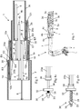
- Telescopic booms 1 according to different embodiments of the present invention are illustrated in Figs 1-3 .
- Each telescopic boom 1 is telescopically extensible and comprises a hollow main section 2 and two or more telescopic boom sections 3a, 3b, 3c carried by the main section 2.
- the telescopic boom sections 3a, 3b, 3c are tubular.
- the telescopic boom sections 3a, 3b, 3c are carried by the main section 2 and displaceable in the longitudinal direction of the main section by means of hydraulic cylinders 4a, 4b, 4c for adjustment of the extension length of the telescopic boom 1.
- Each hydraulic cylinder 4a, 4b, 4c comprises a cylinder tube 5, a piston (not shown) mounted inside the cylinder tube 5 so as to be axially displaceable in relation to the cylinder tube, and a piston rod 6 secured to the piston.
- the hydraulic cylinders 4a, 4b, 4c are hydraulically connected to each other and jointly activated.
- the hydraulic connection of the hydraulic cylinders to each other is for instance implemented by connecting the cylinder chambers on the piston side of the different hydraulic cylinders to each other and further connecting the cylinder chambers on the piston rod side of the different hydraulic cylinders to each other.
- telescopic cylinders may be used.
- the telescopic boom 1 is provided with two telescopic boom sections 3a, 3b and in the embodiments illustrated in Figs 2 and 3 the telescopic boom 1 is provided with three telescopic boom sections 3a, 3b, 3c, but the telescopic boom may also be provided with more than three telescopic boom sections.
- the telescopic boom 1 is telescopically extendable by displacement of the telescopic boom sections 3a, 3b, 3c outwards in relation to the main section 2 and telescopically retractable by displacement of the telescopic boom sections 3a, 3b, 3c inwards in relation to the main section 2.
- a first telescopic boom section 3a is received in the main section 2 and is in sliding contact with an inner wall thereof.
- a second telescopic boom section 3b is received in the first telescopic boom section 3a and is in sliding contact with an inner wall thereof.
- a third telescopic boom section 3c is received in the second telescopic boom section 3b and is in sliding contact with an inner wall thereof.
- the main section 2 and the telescopic boom sections 3a, 3b, 3c are in a conventional manner provided with sliding elements (not shown) in order to allow the third telescopic boom section 3c to be slidingly supported against the second telescopic boom section 3b, the second telescopic boom section 3b to be slidingly supported against the first telescopic boom section 3a and the first telescopic boom section 3a to be slidingly supported against the main section 2.
- the first telescopic boom section 3a is axially displaceable in relation to the main section 2 under the effect of a double-acting first hydraulic cylinder 4a, which is configured to act between the first telescopic boom section 3a and the main section 2.
- the first hydraulic cylinder 4a is arranged with its cylinder tube 5 fixed in axial position in relation to the main section 2 and with its piston rod 6 fixed in axial position in relation to the first telescopic boom section 3a.
- the first hydraulic cylinder 4a could be arranged in the opposite direction with its cylinder tube 5 fixed in axial position in relation to the first telescopic boom section 3a and with its piston rod 6 fixed in axial position in relation to the main section 2.
- the second telescopic boom section 3b is axially displaceable in relation to the first telescopic boom section 3a under the effect of a double-acting second hydraulic cylinder 4b, which is configured to act between the second telescopic boom section 3b and the first telescopic boom section 3a.
- the second hydraulic cylinder 4b is arranged with its cylinder tube 5 fixed in axial position in relation to the first telescopic boom section 3a and with its piston rod 6 fixed in axial position in relation to the second telescopic boom section 3b.
- the second hydraulic cylinder 4b could be arranged in the opposite direction with its cylinder tube 5 fixed in axial position in relation to the second telescopic boom section 3b and with its piston rod 6 fixed in axial position in relation to the first telescopic boom section 3a.
- the third telescopic boom section 3c included in the embodiments illustrated in Figs 2 and 3 is axially displaceable in relation to the second telescopic boom section 3b under the effect of a double-acting third hydraulic cylinder 4c, which is configured to act between the third telescopic boom section 3c and the second telescopic boom section 3b.
- the third hydraulic cylinder 4c is arranged with its cylinder tube 5 fixed in axial position in relation to the second telescopic boom section 3b and with its piston rod 6 fixed in axial position in relation to the third telescopic boom section 3c.
- the third hydraulic cylinder 4c could be arranged in the opposite direction with its cylinder tube 5 fixed in axial position in relation to the third telescopic boom section 3c and with its piston rod 6 fixed in axial position in relation to the second telescopic boom section 3b.
- the hydraulic cylinders 4a, 4b, 4c are mounted inside the telescopic boom 1, but they could alternatively be mounted on the outside of the telescopic boom 1, as illustrated in Fig 5 .
- the telescopic boom 1 comprises six telescopic boom sections 3a-3f.
- the telescopic boom 1 comprises a synchronizing system for synchronizing the mutual axial displacements of the telescopic boom sections 3a, 3b, 3c effected by the hydraulic cylinders 4a, 4b, 4c, wherein the synchronization is effected by means of one or more elongated and flexible synchronizing members 10, 10a, 10b, 20a-20d, for instance in the form of belts, bands, wires, chains or the like, and associated direction changing members 12a-12d, preferably in the form of pulleys or rollers.
- the synchronizing system comprises only one elongated and flexible synchronizing member 10.
- a first point P1 on the synchronizing member 10 is fixed in relation to the main section 2 and a second point P2 on the synchronizing member 10 is fixed in relation to the second telescopic boom section 3b.
- the synchronizing member 10 extends over a first direction changing member 12a fixed to the first telescopic boom section 3a at an outer end thereof and over a second direction changing member 12b fixed to the first telescopic boom section 3a at an inner end thereof.
- the synchronizing member 10 and the direction changing members 12a, 12b will together force the telescopic boom sections 3a, 3b to move in a synchronized manner during the extension and retraction of the telescopic boom 1 effected by the hydraulic cylinders 4a, 4b.
- the first telescopic boom section 3a When the first telescopic boom section 3a is moved axially outwards in relation to the main section 2 under the effect of the first hydraulic cylinder 4a, the first telescopic boom section 3a will exert an outwardly directed pulling force on the second telescopic boom section 3b via the first direction changing member 12a and the synchronizing member 10.
- the second telescopic boom section 3b When the second telescopic boom section 3b is moved axially outwards in relation to the first telescopic boom section 3a under the effect of the second hydraulic cylinder 4b, the second telescopic boom section 3b will exert an outwardly directed pushing force on the first telescopic boom section 3a via the synchronizing member 10 and the second direction changing member 12b.
- the first telescopic boom section 3a When the first telescopic boom section 3a is moved axially inwards in relation to the main section 2 under the effect of the first hydraulic cylinder 4a, the first telescopic boom section 3a will exert an inwardly directed pulling force on the second telescopic boom section 3b via the second direction changing member 12b and the synchronizing member 10.
- the second telescopic boom section 3b When the second telescopic boom section 3b is moved axially inwards in relation to the first telescopic boom section 3a under the effect of the second hydraulic cylinder 4b, the second telescopic boom section 3b will exert an inwardly directed pushing force on the first telescopic boom section 3a via the synchronizing member 10 and the first direction changing member 12a.
- the synchronizing member 10 extends through interspaces between the different sections 2, 3a, 3b of the telescopic boom 1, wherein the synchronizing member 10:
- the synchronizing member 10 illustrated in Fig 1 may as an alternative be replaced by two separate synchronizing members in the manner illustrated in Fig 3 and described in further detail below.
- the synchronizing system comprises a first synchronizing member 10a arranged in the same manner as the synchronizing member 10 illustrated in Fig 1 .
- this first synchronizing member 10a is configured to co-operate with first and second direction changing members 12a, 12b at opposite ends of the first telescopic boom section 3a in order to synchronize the movements of the first and second telescopic boom sections 3a, 3b.
- the synchronizing system further comprises an elongated and flexible second synchronizing member 10b.
- a first point P3 on the second synchronizing member 10b is fixed in relation to the second telescopic boom section 3b and a second point P4 on the second synchronizing member 10b is fixed in relation to the third telescopic boom section 3c.
- the second synchronizing member 10b extends over a third direction changing member 12c fixed to the second telescopic boom section 3b at an outer end thereof and over a fourth direction changing member 12d fixed to the second telescopic boom section 3b at an inner end thereof.
- the second telescopic boom section 3b When the second telescopic boom section 3b is moved axially outwards in relation to the first telescopic boom section 3a under the effect of the second hydraulic cylinder 4b, the second telescopic boom section 3b will exert an outwardly directed pulling force on the third telescopic boom section 3c via the second direction changing member 12b and the second synchronizing member 10b.
- the third telescopic boom section 3c is moved axially outwards in relation to the second telescopic boom section 3b under the effect of the third hydraulic cylinder 4c, the third telescopic boom section 3c will exert an outwardly directed pushing force on the second telescopic boom section 3b via the second synchronizing member 10b and the fourth direction changing member 12d.
- the second telescopic boom section 3b When the second telescopic boom section 3b is moved axially inwards in relation to the first telescopic boom section 3a under the effect of the second hydraulic cylinder 4b, the second telescopic boom section 3b will exert an inwardly directed pulling force on the third telescopic boom section 3c via the fourth direction changing member 12d and the second synchronizing member 10b.
- the third telescopic boom section 3c is moved axially inwards in relation to the second telescopic boom section 3b under the effect of the third hydraulic cylinder 4c, the third telescopic boom section 3c will exert an inwardly directed pushing force on the second telescopic boom section 3b via the second synchronizing member 10b and the third direction changing member 12c.
- the second synchronizing member 10b extends through interspaces between the telescopic boom sections 3a, 3b, 3c, wherein the second synchronizing member 10b:
- each synchronizing member 10a, 10b included in the telescopic boom shown in Fig 2 is replaced by two separate synchronizing members.
- the synchronizing system comprises:
- the first synchronizing member 20a extends on the outside of the first telescopic boom section 3a, and between its second end E2 and the first direction changing member 12a, the first synchronizing member 20a extends in a gap 15 between the first and second telescopic boom sections 3a, 3b.
- the second synchronizing member 20b extends in a gap 14 between the main section 2 and the first telescopic boom section 3a, and between its second end E4 and the second direction changing member 12b, the second synchronizing member 20b extends on the inside of the first telescopic boom section 3a.
- the third synchronizing member 20c extends on the outside of the second telescopic boom section 3b, and between its second end E6 and the third direction changing member 12c, the third synchronizing member 20c extends in a gap 17 between the second and third telescopic boom sections 3b, 3c.
- the fourth synchronizing member 20d extends in a gap 16 between the first and second telescopic boom sections 3a, 3b, and between its second end E8 and the fourth direction changing member 12d, the fourth synchronizing member 20d extends on the inside of the second telescopic boom section 3b.
- each synchronizing member 20a-20d is associated with a pre-tensioning mechanism 30, wherein each pre-tensioning mechanism 30 is configured to act on the associated synchronizing member 20a-20d so as to keep it stretched out and prevent it from slacking when the telescopic boom sections 3a-3c are axially displaced in relation to each other.
- Each pre-tensioning mechanism 30 preferably comprises a compression spring 31 (see Figs 4a and 4b ), which is configured to exert a pulling force on the associated synchronizing member 20a-20d.
- the compression spring 31 is arranged between a support member 32, attached to the telescopic boom section, and a stop member 33, such as a washer, wherein the compression spring 31 at a first end is fixed to or abuts against the support member 32 and at an opposite second end is fixed to or abuts against the stop member 33.
- An elongated rod 34 extends through a through hole in the support member 32, through the compression spring 31 and through a through hole in the stop member 33, wherein the stop member 33 is fixed to the rod 34 by means of a nut 35, which is threaded onto a threaded end part of the rod 34.
- An attachment 36 is fixed to the rod 34 at the opposite end thereof.
- the synchronizing member 20a has one of its ends fixed to the attachment 36 to thereby allow the synchronizing member 20a to exert a pushing force on the compression spring 31 via the rod 34 and the stop member 33 when the synchronizing member 20a is subjected to tensile stress under the effect of the associated direction changing member 12a,
- the spring force stored in the compression spring 31 will then allow the compression spring 31 to exert a pulling force on the synchronizing member 20a via the stop member 33 and the rod 34 if the tensile stress on the synchronizing member 20a ceases, to thereby pull the end of the synchronizing member 20a closer to the support member 32, as illustrated in Fig 4b , and prevent the synchronizing member 20a from slacking.
- pre-tensioning mechanism 30 could be replaced by a corresponding resiliency integrated in a part of the synchronizing member 20a-20d itself.
- the direction changing members 12a-12d are preferably rotatably mounted to the telescopic boom sections.
- the telescopic boom 1 may for instance constitute a crane boom, as illustrated in Fig 5 , in which case the main section 2 of the telescopic boom could be articulately connected to a part 7 of a hydraulic crane 8, for instance a vehicle crane, so as to be pivotable about a horizontal axis in relation to this crane part 7.
Landscapes
- Engineering & Computer Science (AREA)
- Mechanical Engineering (AREA)
- Jib Cranes (AREA)
Abstract
Description
- The present invention relates to a telescopic boom according to the preamble of
claim 1. The invention also relates to a hydraulic crane comprising a telescopic boom. - Telescopically extendable and retractable booms are known in various configurations and may for instance be included in different types of hydraulic cranes. In a telescopic boom having two or more telescopically displaceable boom sections, every telescopic boom section may be provided with its own hydraulic cylinder in order to control the extension and retraction thereof. The hydraulic cylinders of a telescopic boom are normally hydraulically connected to each other and jointly activated. Approximately the same hydraulic pressure is built up in the chambers of the hydraulic cylinders when they are activated, which implies that the hydraulic cylinder that experiences the lowest resistance, for instance from friction, will move first. In this case, the sequence in which the telescopic boom sections are moved during extension and retraction of the telescopic boom will depend on the frictional forces between the individual boom sections, which may result in a sequence that is unfavourable with respect to the strength and lifting capacity of the telescopic boom. In order to avoid a random movement of the telescopic boom sections, the hydraulic system may be so designed that the hydraulic cylinders of the telescopic boom sections are actuated in a predefined sequence. However, such a solution requires a hydraulic system of a rather expensive and complicated construction and is also associated with other drawbacks.
- It is also known to use a single hydraulic cylinder for displacing a first telescopic boom section in relation to a non-displaceable main section of a telescopic boom and one or more elongated and flexible transmission members, e.g. in the form of belts or chains, for displacing one or more further telescopic boom sections in relation to the first telescopic boom section and in relation to each other. Such a solution with a synchronized movement of the telescopic boom sections is associated with several advantages and is for instance disclosed in
US 5 060 427 A . - In this application, a synchronized movement of the telescopic boom sections of a telescopic boom refers to a concurrent movement of the telescopic boom sections such that they are all extended and retracted the same distance and simultaneously. With such a synchronized movement, there is no risk that the weakest telescopic boom section at the outer end of the telescopic boom will go out first before the other telescopic boom sections and get overloaded. A synchronized movement of the telescopic boom sections also offers lower fatigue wear of the telescopic boom sections.
- The object of the present invention is to provide a telescopic boom of new and advantageous design.
- According to the present invention, said object is achieved by means of a telescopic boom having the features defined in
claim 1. - The telescopic boom of the present invention comprises:
- a main section;
- two or more telescopic boom sections which are carried by the main section and displaceable in the longitudinal direction of the main section, wherein a first telescopic boom section is telescopically mounted in the main section and axially displaceable in relation to it under the effect of a first hydraulic cylinder which is configured to act between the first telescopic boom section and the main section, and wherein each further telescopic boom section is telescopically mounted in an adjacent telescopic boom section and axially displaceable in relation to it under the effect of another hydraulic cylinder which is configured to act between this further telescopic boom section and this adjacent telescopic boom section; and
- a synchronizing system with one or more elongated and flexible synchronizing members and associated direction changing members, preferably in the form of pulleys or rollers, wherein the synchronizing members and the direction changing members are configured to co-operate to synchronize the mutual axial displacements of the telescopic boom sections effected by said hydraulic cylinders.
- The above-mentioned synchronizing system ensures a synchronized actuation of the telescopic boom sections without requiring any expensive and complicated construction of the hydraulic system to which the hydraulic cylinders are connected. The hydraulic cylinder between the main section and the first telescopic boom section and the hydraulic cylinders between the telescopic boom sections will together carry the axial load on the telescopic boom. Owing to the fact that the axial load on the telescopic boom is taken up by the hydraulic cylinders and not by any of the synchronizing members, the synchronizing members only have to be dimensioned to be capable of equalizing the different frictional forces between the telescopic boom sections, which implies reduced requirements with respect to the strength of the synchronizing members as compared to a synchronized telescopic boom of conventional design where the synchronizing members also have to carry the axial load on the telescopic boom. Furthermore, since the axial load on the telescopic boom is carried by the hydraulic cylinders, there is no risk that the telescopic boom will collapse in case one or more of the synchronizing members would be broken off. In fact, the telescopic boom may continue to function properly in such a situation, albeit with no synchronized movement of the telescopic boom sections. The reduced demands on the synchronizing members and the associated direction changing members imply that the synchronizing system may be constructed in a space-saving manner and at comparatively low cost.
- According to an embodiment of the invention, each synchronizing member is associated with a pre-tensioning mechanism, wherein each pre-tensioning mechanism is configured to act on the associated synchronizing member so as to keep it stretched out and prevent it from slacking when the telescopic boom sections are axially displaced in relation to each other. Hereby, problems associated with slacking synchronizing members are avoided.
- Further advantageous features of the telescopic boom according to the present invention will appear from the description following below and the dependent claims.
- The invention also relates to a hydraulic crane having the features defined in
claim 15. - The invention will in the following be more closely described by means of embodiment examples, with reference to the appended drawings. In the drawings:
- Fig 1
- is a schematic longitudinal section through a telescopic boom according to a first embodiment of the present invention,
- Fig 2
- is a schematic longitudinal section through a telescopic boom according to a second embodiment of the invention,
- Fig 3
- is a schematic longitudinal section through a telescopic boom according to a third embodiment of the invention,
- Fig 4a
- is a schematic lateral view of a pre-tensioning mechanism included in the telescopic boom of
Fig 3 , as seen with a compression spring of the pre-tensioning mechanism in a compressed state, - Fig 4b
- is a schematic lateral view of the pre-tensioning mechanism of
Fig 4a , as seen with the compression spring in an expanded state, and - Fig 5
- is a lateral view of a telescopic boom according to a fourth embodiment of the invention.
-
Telescopic booms 1 according to different embodiments of the present invention are illustrated inFigs 1-3 . Eachtelescopic boom 1 is telescopically extensible and comprises a hollowmain section 2 and two or moretelescopic boom sections main section 2. Thetelescopic boom sections telescopic boom sections main section 2 and displaceable in the longitudinal direction of the main section by means ofhydraulic cylinders telescopic boom 1. - Each
hydraulic cylinder cylinder tube 5, a piston (not shown) mounted inside thecylinder tube 5 so as to be axially displaceable in relation to the cylinder tube, and apiston rod 6 secured to the piston. Thehydraulic cylinders - In the embodiment illustrated in
Fig 1 thetelescopic boom 1 is provided with twotelescopic boom sections Figs 2 and3 thetelescopic boom 1 is provided with threetelescopic boom sections telescopic boom 1 is telescopically extendable by displacement of thetelescopic boom sections main section 2 and telescopically retractable by displacement of thetelescopic boom sections main section 2. - A first
telescopic boom section 3a is received in themain section 2 and is in sliding contact with an inner wall thereof. A secondtelescopic boom section 3b is received in the firsttelescopic boom section 3a and is in sliding contact with an inner wall thereof. In the embodiments illustrated inFigs 2 and3 , a thirdtelescopic boom section 3c is received in the secondtelescopic boom section 3b and is in sliding contact with an inner wall thereof. Themain section 2 and thetelescopic boom sections telescopic boom section 3c to be slidingly supported against the secondtelescopic boom section 3b, the secondtelescopic boom section 3b to be slidingly supported against the firsttelescopic boom section 3a and the firsttelescopic boom section 3a to be slidingly supported against themain section 2. - The first
telescopic boom section 3a is axially displaceable in relation to themain section 2 under the effect of a double-acting firsthydraulic cylinder 4a, which is configured to act between the firsttelescopic boom section 3a and themain section 2. In the illustrated example, the firsthydraulic cylinder 4a is arranged with itscylinder tube 5 fixed in axial position in relation to themain section 2 and with itspiston rod 6 fixed in axial position in relation to the firsttelescopic boom section 3a. As an alternative, the firsthydraulic cylinder 4a could be arranged in the opposite direction with itscylinder tube 5 fixed in axial position in relation to the firsttelescopic boom section 3a and with itspiston rod 6 fixed in axial position in relation to themain section 2. As an alternative to using a double-actinghydraulic cylinder 4a for displacing the firsttelescopic boom section 3a in relation to themain section 2, it would also be possible to use one single-acting hydraulic cylinder for displacing the firsttelescopic boom section 3a axially outwards in relation to themain section 2 and another single-acting hydraulic cylinder for displacing the firsttelescopic boom section 3a axially inwards in relation to themain section 2. - The second
telescopic boom section 3b is axially displaceable in relation to the firsttelescopic boom section 3a under the effect of a double-acting secondhydraulic cylinder 4b, which is configured to act between the secondtelescopic boom section 3b and the firsttelescopic boom section 3a. In the illustrated example, the secondhydraulic cylinder 4b is arranged with itscylinder tube 5 fixed in axial position in relation to the firsttelescopic boom section 3a and with itspiston rod 6 fixed in axial position in relation to the secondtelescopic boom section 3b. As an alternative, the secondhydraulic cylinder 4b could be arranged in the opposite direction with itscylinder tube 5 fixed in axial position in relation to the secondtelescopic boom section 3b and with itspiston rod 6 fixed in axial position in relation to the firsttelescopic boom section 3a. As an alternative to using a double-actinghydraulic cylinder 4b for displacing the secondtelescopic boom section 3b in relation to the firsttelescopic boom section 3a, it would also be possible to use one single-acting hydraulic cylinder for displacing the secondtelescopic boom section 3b axially outwards in relation to the firsttelescopic boom section 3a and another single-acting hydraulic cylinder for displacing the secondtelescopic boom section 3b axially inwards in relation to the firsttelescopic boom section 3a. - The third
telescopic boom section 3c included in the embodiments illustrated inFigs 2 and3 is axially displaceable in relation to the secondtelescopic boom section 3b under the effect of a double-acting thirdhydraulic cylinder 4c, which is configured to act between the thirdtelescopic boom section 3c and the secondtelescopic boom section 3b. In the illustrated examples, the thirdhydraulic cylinder 4c is arranged with itscylinder tube 5 fixed in axial position in relation to the secondtelescopic boom section 3b and with itspiston rod 6 fixed in axial position in relation to the thirdtelescopic boom section 3c. As an alternative, the thirdhydraulic cylinder 4c could be arranged in the opposite direction with itscylinder tube 5 fixed in axial position in relation to the thirdtelescopic boom section 3c and with itspiston rod 6 fixed in axial position in relation to the secondtelescopic boom section 3b. As an alternative to using a double-actinghydraulic cylinder 4c for displacing the thirdtelescopic boom section 3c in relation to the secondtelescopic boom section 3b, it would also be possible to use one single-acting hydraulic cylinder for displacing the thirdtelescopic boom section 3c axially outwards in relation to the secondtelescopic boom section 3b and another single-acting hydraulic cylinder for displacing the thirdtelescopic boom section 3c axially inwards in relation to the secondtelescopic boom section 3b. - In the embodiments illustrated in
Figs 1-3 , thehydraulic cylinders telescopic boom 1, but they could alternatively be mounted on the outside of thetelescopic boom 1, as illustrated inFig 5 . In the embodiment illustrated inFig 5 , thetelescopic boom 1 comprises sixtelescopic boom sections 3a-3f. - According to the invention, the
telescopic boom 1 comprises a synchronizing system for synchronizing the mutual axial displacements of thetelescopic boom sections hydraulic cylinders flexible synchronizing members direction changing members 12a-12d, preferably in the form of pulleys or rollers. - In the embodiment illustrated in
Fig 1 , the synchronizing system comprises only one elongated and flexible synchronizingmember 10. A first point P1 on the synchronizingmember 10 is fixed in relation to themain section 2 and a second point P2 on the synchronizingmember 10 is fixed in relation to the secondtelescopic boom section 3b. The synchronizingmember 10 extends over a firstdirection changing member 12a fixed to the firsttelescopic boom section 3a at an outer end thereof and over a seconddirection changing member 12b fixed to the firsttelescopic boom section 3a at an inner end thereof. - The synchronizing
member 10 and thedirection changing members telescopic boom sections telescopic boom 1 effected by thehydraulic cylinders - When the first
telescopic boom section 3a is moved axially outwards in relation to themain section 2 under the effect of the firsthydraulic cylinder 4a, the firsttelescopic boom section 3a will exert an outwardly directed pulling force on the secondtelescopic boom section 3b via the firstdirection changing member 12a and the synchronizingmember 10. When the secondtelescopic boom section 3b is moved axially outwards in relation to the firsttelescopic boom section 3a under the effect of the secondhydraulic cylinder 4b, the secondtelescopic boom section 3b will exert an outwardly directed pushing force on the firsttelescopic boom section 3a via the synchronizingmember 10 and the seconddirection changing member 12b. - When the first
telescopic boom section 3a is moved axially inwards in relation to themain section 2 under the effect of the firsthydraulic cylinder 4a, the firsttelescopic boom section 3a will exert an inwardly directed pulling force on the secondtelescopic boom section 3b via the seconddirection changing member 12b and the synchronizingmember 10. When the secondtelescopic boom section 3b is moved axially inwards in relation to the firsttelescopic boom section 3a under the effect of the secondhydraulic cylinder 4b, the secondtelescopic boom section 3b will exert an inwardly directed pushing force on the firsttelescopic boom section 3a via the synchronizingmember 10 and the firstdirection changing member 12a. - In the illustrated example, the synchronizing
member 10 extends through interspaces between thedifferent sections telescopic boom 1, wherein the synchronizing member 10: - between its first point P1 and the second
direction changing member 12b extends in agap 14 between themain section 2 and the firsttelescopic boom section 3a; - between its second point P2 and the first
direction changing member 12a extends in agap 15 between the first and secondtelescopic boom sections - between its first point P1 and the first
direction changing member 12a extends along the outside of the firsttelescopic boom section 3a; and - between its second point P2 and the second
direction changing member 12b, extends along the inside of the firsttelescopic boom section 3a. - The synchronizing
member 10 illustrated inFig 1 may as an alternative be replaced by two separate synchronizing members in the manner illustrated inFig 3 and described in further detail below. - In the embodiment illustrated in
Fig 2 , the synchronizing system comprises afirst synchronizing member 10a arranged in the same manner as the synchronizingmember 10 illustrated inFig 1 . Thus, this first synchronizingmember 10a is configured to co-operate with first and seconddirection changing members telescopic boom section 3a in order to synchronize the movements of the first and secondtelescopic boom sections - In the embodiment illustrated in
Fig 2 , the synchronizing system further comprises an elongated and flexiblesecond synchronizing member 10b. A first point P3 on thesecond synchronizing member 10b is fixed in relation to the secondtelescopic boom section 3b and a second point P4 on thesecond synchronizing member 10b is fixed in relation to the thirdtelescopic boom section 3c. Thesecond synchronizing member 10b extends over a thirddirection changing member 12c fixed to the secondtelescopic boom section 3b at an outer end thereof and over a fourthdirection changing member 12d fixed to the secondtelescopic boom section 3b at an inner end thereof. - When the second
telescopic boom section 3b is moved axially outwards in relation to the firsttelescopic boom section 3a under the effect of the secondhydraulic cylinder 4b, the secondtelescopic boom section 3b will exert an outwardly directed pulling force on the thirdtelescopic boom section 3c via the seconddirection changing member 12b and thesecond synchronizing member 10b. When the thirdtelescopic boom section 3c is moved axially outwards in relation to the secondtelescopic boom section 3b under the effect of the thirdhydraulic cylinder 4c, the thirdtelescopic boom section 3c will exert an outwardly directed pushing force on the secondtelescopic boom section 3b via thesecond synchronizing member 10b and the fourthdirection changing member 12d. - When the second
telescopic boom section 3b is moved axially inwards in relation to the firsttelescopic boom section 3a under the effect of the secondhydraulic cylinder 4b, the secondtelescopic boom section 3b will exert an inwardly directed pulling force on the thirdtelescopic boom section 3c via the fourthdirection changing member 12d and thesecond synchronizing member 10b. When the thirdtelescopic boom section 3c is moved axially inwards in relation to the secondtelescopic boom section 3b under the effect of the thirdhydraulic cylinder 4c, the thirdtelescopic boom section 3c will exert an inwardly directed pushing force on the secondtelescopic boom section 3b via thesecond synchronizing member 10b and the thirddirection changing member 12c. - In the illustrated example, the
second synchronizing member 10b extends through interspaces between thetelescopic boom sections second synchronizing member 10b: - between its first point P3 and the fourth
direction changing member 12d extends in agap 16 between the first and secondtelescopic boom sections - between its second point P4 and the third
direction changing member 12c extends in agap 17 between the second and thirdtelescopic boom sections - between its first point P3 and the third
direction changing member 12c extends along the outside of the secondtelescopic boom section 3b; and - between its second point P4 and the fourth
direction changing member 12d, extends along the inside of the secondtelescopic boom section 3b. - In the embodiment illustrated in
Fig 3 , each synchronizingmember Fig 2 is replaced by two separate synchronizing members. In this case, the synchronizing system comprises: - a first elongated and
flexible synchronizing member 20a, which has a first end E1 fixed to themain section 2 and a second end E2 fixed to the secondtelescopic boom section 3b, wherein the first synchronizingmember 20a extends over a firstdirection changing member 12a fixed to the firsttelescopic boom section 3a at an outer end thereof; - a second elongated and
flexible synchronizing member 20b, which has a first end E3 fixed to themain section 2 and a second end E4 fixed to the secondtelescopic boom section 3b, wherein thesecond synchronizing member 20b extends over a seconddirection changing member 12b fixed to the firsttelescopic boom section 3a at an inner end thereof; - a third elongated and flexible synchronizing
member 20c, which has a first end E5 fixed to the firsttelescopic boom section 3a and a second end E6 fixed to the thirdtelescopic boom section 3c, wherein the third synchronizingmember 20c extends over a thirddirection changing member 12c fixed to the secondtelescopic boom section 3b at an outer end thereof; and - a fourth elongated and
flexible synchronizing member 20d, which has a first end E7 fixed to the firsttelescopic boom section 3a and a second end E8 fixed to the thirdtelescopic boom section 3c, wherein the fourth synchronizingmember 20d extends over a fourthdirection changing member 12d fixed to the secondtelescopic boom section 3b at an inner end thereof. - Between its first end E1 and the first
direction changing member 12a, the first synchronizingmember 20a extends on the outside of the firsttelescopic boom section 3a, and between its second end E2 and the firstdirection changing member 12a, the first synchronizingmember 20a extends in agap 15 between the first and secondtelescopic boom sections - Between its first end E3 and the second
direction changing member 12b, thesecond synchronizing member 20b extends in agap 14 between themain section 2 and the firsttelescopic boom section 3a, and between its second end E4 and the seconddirection changing member 12b, thesecond synchronizing member 20b extends on the inside of the firsttelescopic boom section 3a. - Between its first end E5 and the third
direction changing member 12c, the third synchronizingmember 20c extends on the outside of the secondtelescopic boom section 3b, and between its second end E6 and the thirddirection changing member 12c, the third synchronizingmember 20c extends in agap 17 between the second and thirdtelescopic boom sections - Between its first end E7 and the fourth
direction changing member 12d, the fourth synchronizingmember 20d extends in agap 16 between the first and secondtelescopic boom sections direction changing member 12d, the fourth synchronizingmember 20d extends on the inside of the secondtelescopic boom section 3b. - In the embodiment illustrated in
Fig 3 , each synchronizingmember 20a-20d is associated with apre-tensioning mechanism 30, wherein eachpre-tensioning mechanism 30 is configured to act on the associated synchronizingmember 20a-20d so as to keep it stretched out and prevent it from slacking when thetelescopic boom sections 3a-3c are axially displaced in relation to each other. Eachpre-tensioning mechanism 30 preferably comprises a compression spring 31 (seeFigs 4a and 4b ), which is configured to exert a pulling force on the associated synchronizingmember 20a-20d. - In the example illustrated in
Figs 4a and 4b , thecompression spring 31 is arranged between asupport member 32, attached to the telescopic boom section, and astop member 33, such as a washer, wherein thecompression spring 31 at a first end is fixed to or abuts against thesupport member 32 and at an opposite second end is fixed to or abuts against thestop member 33. Anelongated rod 34 extends through a through hole in thesupport member 32, through thecompression spring 31 and through a through hole in thestop member 33, wherein thestop member 33 is fixed to therod 34 by means of anut 35, which is threaded onto a threaded end part of therod 34. Anattachment 36 is fixed to therod 34 at the opposite end thereof. The synchronizingmember 20a has one of its ends fixed to theattachment 36 to thereby allow the synchronizingmember 20a to exert a pushing force on thecompression spring 31 via therod 34 and thestop member 33 when the synchronizingmember 20a is subjected to tensile stress under the effect of the associateddirection changing member 12a, The spring force stored in thecompression spring 31 will then allow thecompression spring 31 to exert a pulling force on the synchronizingmember 20a via thestop member 33 and therod 34 if the tensile stress on the synchronizingmember 20a ceases, to thereby pull the end of the synchronizingmember 20a closer to thesupport member 32, as illustrated inFig 4b , and prevent the synchronizingmember 20a from slacking. - As an alternative, the above-mentioned
pre-tensioning mechanism 30 could be replaced by a corresponding resiliency integrated in a part of the synchronizingmember 20a-20d itself. - The
direction changing members 12a-12d are preferably rotatably mounted to the telescopic boom sections. - The
telescopic boom 1 according to the present invention may for instance constitute a crane boom, as illustrated inFig 5 , in which case themain section 2 of the telescopic boom could be articulately connected to apart 7 of ahydraulic crane 8, for instance a vehicle crane, so as to be pivotable about a horizontal axis in relation to thiscrane part 7. - The invention is of course not in any way restricted to the embodiments described above. On the contrary, many possibilities to modifications thereof will be apparent to a person with ordinary skill in the art without departing from the basic idea of the invention as defined in the appended claims.
Claims (15)
- A telescopic boom comprising a main section (2) and two or more telescopic boom sections (3a, 3b, 3c) which are carried by the main section (2) and displaceable in the longitudinal direction of the main section,
wherein a first telescopic boom section (3a) is telescopically mounted in the main section (2) and axially displaceable in relation to it under the effect of a first hydraulic cylinder (4a) which is configured to act between the first telescopic boom section (3a) and the main section (2), and
wherein each further telescopic boom section (3b, 3c) is telescopically mounted in an adjacent telescopic boom section (3a, 3b) and axially displaceable in relation to it under the effect of another hydraulic cylinder (4b, 4c) which is configured to act between this further telescopic boom section (3b, 3c) and this adjacent telescopic boom section (3a, 3b), characterized in that the telescopic boom (1) comprises a synchronizing system with one or more elongated and flexible synchronizing members (10; 10a, 10b; 20a-20d) and associated direction changing members (12a-12d), preferably in the form of pulleys or rollers, wherein the synchronizing members and the direction changing members are configured to co-operate to synchronize the mutual axial displacements of the telescopic boom sections (3a-3c) effected by said hydraulic cylinders (4a-4c). - A telescopic boom according to claim 1, characterized in that a second telescopic boom section (3b) is telescopically mounted in the first telescopic boom section (3a) and axially displaceable in relation to it under the effect of a second hydraulic cylinder (4b) which is configured to act between the first and second telescopic boom sections (3a, 3b).
- A telescopic boom according to claim 2, characterized in:- that the synchronizing system comprises a first elongated and flexible synchronizing member (10; 10a), wherein a first point (P1) on the first synchronizing member (10; 10a) is fixed in relation to the main section (2) and a second point (P2) on the first synchronizing member (10; 10a) is fixed in relation to the second telescopic boom section (3b); and- that the first synchronizing member (10; 10a) extends over a first direction changing member (12a) fixed to the first telescopic boom section (3a) at an outer end thereof and over a second direction changing member (12b) fixed to the first telescopic boom section (3a) at an inner end thereof.
- A telescopic boom according to claim 3, characterized in:- that the first synchronizing member (10; 10a), between its first point (P1) and the first direction changing member (12a), extends along the outside of the first telescopic boom section (3a);- that the first synchronizing member (10; 10a), between its first point (P1) and the second direction changing member (12b), extends in a gap (14) between the main section (2) and the first telescopic boom section (3a);- that the first synchronizing member (10; 10a), between its second point (P2) and the first direction changing member (12a) extends in a gap (15) between the first and second telescopic boom sections (3a, 3b); and- that the first synchronizing member (10; 10a), between its second point (P2) and the second direction changing member (12b), extends along the inside of the first telescopic boom section (3a).
- A telescopic boom according to claim 3 or 4, characterized in:- that a third telescopic boom section (3c) is telescopically mounted in the second telescopic boom section (3b) and axially displaceable in relation to it under the effect of a third hydraulic cylinder (4c) which is configured to act between the second and third telescopic boom sections (3b, 3c);- that the synchronizing system comprises a second elongated and flexible synchronizing member (10b), which has a first point (P3) fixed in relation to the first telescopic boom section (3a) and a second point (P4) fixed in relation to the third telescopic boom section (3c); and- that the second synchronizing member (10b) extends over a third direction changing member (12c) fixed to the second telescopic boom section (3b) at an outer end thereof and over a fourth direction changing member (12d) fixed to the second telescopic boom section (3b) at an inner end thereof.
- A telescopic boom according to claim 5, characterized in:- that the second synchronizing member (10b), between its first point (P3) and the third direction changing member (12c), extends along the outside of the second telescopic boom section (3b);- that the second synchronizing member (10b), between its first point (P3) and the fourth direction changing member (12d), extends in a gap (16) between the first and second telescopic boom sections (3a, 3b);- that the second synchronizing member (10b), between its second point (P4) and the third direction changing member (12c) extends in a gap (17) between the second and third telescopic boom sections (3b, 3c); and- that the second synchronizing member (10b), between its second point (P4) and the fourth direction changing member (12d), extends along the inside of the second telescopic boom section (3b).
- A telescopic boom according to claim 2, characterized in:- that the synchronizing system comprises a first elongated and flexible synchronizing member (20a), which has a first end (E1) fixed to the main section (2) and a second end (E2) fixed to the second telescopic boom section (3b), wherein the first synchronizing member (20a) extends over a first direction changing member (12a) fixed to the first telescopic boom section (3a) at an outer end thereof; and- that the synchronizing system comprises a second elongated and flexible synchronizing member (20b), which has a first end (E3) fixed to the main section (2) and a second end (E4) fixed to the second telescopic boom section (3b), wherein the second synchronizing member (20b) extends over a second direction changing member (12b) fixed to the first telescopic boom section (3a) at an inner end thereof.
- A telescopic boom according to claim 7, characterized in:- that the first synchronizing member (20a), between its first end (E1) and the first direction changing member (12a), extends along the outside of the first telescopic boom section (3a); and- that the first synchronizing member (20a), between its second end (E2) and the first direction changing member (12a), extends in a gap (15) between the first and second telescopic boom sections (3a, 3b).
- A telescopic boom according to claim 7 or 8, characterized in:- that the second synchronizing member (20b), between its first end (E3) and the second direction changing member (12b), extends in a gap (14) between the main section (2) and the first telescopic boom section (3a); and- that the second synchronizing member (20b), between its second end (E4) and the second direction changing member (12b), extends along the inside of the first telescopic boom section (3a).
- A telescopic boom according to any of claims 7-9, characterized in:- that a third telescopic boom section (3c) is telescopically mounted in the second telescopic boom section (3b) and axially displaceable in relation to it under the effect of a third hydraulic cylinder (4c) which is configured to act between the second and third telescopic boom sections (3b, 3c);- that the synchronizing system comprises a third elongated and flexible synchronizing member (20c), which has a first end (E5) fixed to the first telescopic boom section (3a) and a second end (E6) fixed to the third telescopic boom section (3c), wherein the third synchronizing member (20c) extends over a third direction changing member (12c) fixed to the second telescopic boom section (3b) at an outer end thereof; and- that the synchronizing system comprises a fourth elongated and flexible synchronizing member (20d), which has a first end (E7) fixed to the first telescopic boom section (3a) and a second end (E8) fixed to the third telescopic boom section (3c), wherein the fourth synchronizing member (20d) extends over a fourth direction changing member (12d) fixed to the second telescopic boom section (3b) at an inner end thereof.
- A telescopic boom according to claim 10, characterized in:- that the third synchronizing member (20c), between its first end (E5) and the third direction changing member (12c), extends along the outside of the second telescopic boom section (3b); and- that the third synchronizing member (20c), between its second end (E6) and the third direction changing member (12c), extends in a gap (17) between the second and third telescopic boom sections (3b, 3c).
- A telescopic boom according to claim 10 or 11, characterized in:- that the fourth synchronizing member (20d), between its first end (E7) and the fourth direction changing member (12d), extends in a gap (16) between the first and second telescopic boom sections (3a, 3b); and- that the fourth synchronizing member (20d), between its second end (E8) and the fourth direction changing member (12d), extends along the inside of the second telescopic boom section (3b).
- A telescopic boom according to any of claims 7-12, characterized in that each synchronizing member (20a-20d) is associated with a pre-tensioning mechanism (30), wherein each pre-tensioning mechanism (30) is configured to act on the associated synchronizing member (20a-20d) so as to keep it stretched out and prevent it from slacking when the telescopic boom sections are axially displaced in relation to each other.
- A telescopic boom according to claim 13, characterized in that at least one of said pre-tensioning mechanisms (30) comprises a compression spring (31), which is configured to exert a pulling force on the associated synchronizing member (20a-20d).
- A hydraulic crane, characterized in that the hydraulic crane (8) comprises a telescopic boom (1) according to any of claims 1-14.
Priority Applications (1)
| Application Number | Priority Date | Filing Date | Title |
|---|---|---|---|
| EP19181329.4A EP3753897A1 (en) | 2019-06-19 | 2019-06-19 | Telescopic boom and hydraulic crane comprising a telescopic boom |
Applications Claiming Priority (1)
| Application Number | Priority Date | Filing Date | Title |
|---|---|---|---|
| EP19181329.4A EP3753897A1 (en) | 2019-06-19 | 2019-06-19 | Telescopic boom and hydraulic crane comprising a telescopic boom |
Publications (1)
| Publication Number | Publication Date |
|---|---|
| EP3753897A1 true EP3753897A1 (en) | 2020-12-23 |
Family
ID=66999643
Family Applications (1)
| Application Number | Title | Priority Date | Filing Date |
|---|---|---|---|
| EP19181329.4A Withdrawn EP3753897A1 (en) | 2019-06-19 | 2019-06-19 | Telescopic boom and hydraulic crane comprising a telescopic boom |
Country Status (1)
| Country | Link |
|---|---|
| EP (1) | EP3753897A1 (en) |
Cited By (1)
| Publication number | Priority date | Publication date | Assignee | Title |
|---|---|---|---|---|
| CN113682981A (en) * | 2021-09-09 | 2021-11-23 | 大洋泊车股份有限公司 | Flexible arm of platform fire engine ascends a height |
Citations (5)
| Publication number | Priority date | Publication date | Assignee | Title |
|---|---|---|---|---|
| US5060427A (en) * | 1990-02-01 | 1991-10-29 | Kidde Industries, Inc. | Extension and retraction system for four section telescopic boom having simultaneous and equal extension and retraction of the telescopic sections |
| JPH0455296A (en) * | 1990-06-25 | 1992-02-21 | Komatsu Ltd | Crane truck boom extension device |
| JP2001107383A (en) * | 1999-10-07 | 2001-04-17 | Kobelco Contstruction Machinery Ltd | Multi-stage telescopic arm for construction machinery |
| JP3986592B2 (en) * | 1996-09-02 | 2007-10-03 | 株式会社タダノ | Multi-stage telescopic boom simultaneous telescopic device |
| US9815669B2 (en) * | 2012-07-06 | 2017-11-14 | C.M.C. S.r.l.—Societa Unipersonale | Telescopic arm for operating machines |
-
2019
- 2019-06-19 EP EP19181329.4A patent/EP3753897A1/en not_active Withdrawn
Patent Citations (5)
| Publication number | Priority date | Publication date | Assignee | Title |
|---|---|---|---|---|
| US5060427A (en) * | 1990-02-01 | 1991-10-29 | Kidde Industries, Inc. | Extension and retraction system for four section telescopic boom having simultaneous and equal extension and retraction of the telescopic sections |
| JPH0455296A (en) * | 1990-06-25 | 1992-02-21 | Komatsu Ltd | Crane truck boom extension device |
| JP3986592B2 (en) * | 1996-09-02 | 2007-10-03 | 株式会社タダノ | Multi-stage telescopic boom simultaneous telescopic device |
| JP2001107383A (en) * | 1999-10-07 | 2001-04-17 | Kobelco Contstruction Machinery Ltd | Multi-stage telescopic arm for construction machinery |
| US9815669B2 (en) * | 2012-07-06 | 2017-11-14 | C.M.C. S.r.l.—Societa Unipersonale | Telescopic arm for operating machines |
Cited By (2)
| Publication number | Priority date | Publication date | Assignee | Title |
|---|---|---|---|---|
| CN113682981A (en) * | 2021-09-09 | 2021-11-23 | 大洋泊车股份有限公司 | Flexible arm of platform fire engine ascends a height |
| CN113682981B (en) * | 2021-09-09 | 2023-03-10 | 大洋泊车股份有限公司 | Flexible arm of platform fire engine ascends a height |
Similar Documents
| Publication | Publication Date | Title |
|---|---|---|
| KR101278122B1 (en) | Locking system for a telescopic crane jib with movable locking unit | |
| JP5706804B2 (en) | Telescopic system for crane jib and auxiliary jib | |
| EP3199485B1 (en) | A telescopic arm for self-propelled operating machines | |
| WO2015194268A1 (en) | Extension and retraction device for telescopic boom | |
| US4733598A (en) | Telescopic jib | |
| CN104955763A (en) | A telescopic boom | |
| JP6405880B2 (en) | Telescopic boom telescopic device | |
| US6244450B1 (en) | Method and apparatus for telescoping boom with hydraulic extension actuators | |
| US5465855A (en) | Telescoping crane arm | |
| US8215503B2 (en) | Crane with telescopic boom | |
| EP3532424A1 (en) | Foldable crane | |
| US5060427A (en) | Extension and retraction system for four section telescopic boom having simultaneous and equal extension and retraction of the telescopic sections | |
| CN111517235B (en) | Telescopic mechanism, boom and aerial work equipment | |
| EP2096075A1 (en) | Telescopic boom | |
| CN204138216U (en) | The boom telescoping device of car hosit | |
| DE19631547B4 (en) | Telescopic boom, especially for stationary or mobile cranes | |
| GB2068330A (en) | Telescopic crane jib | |
| CN102774790B (en) | Telescopic booms and construction machinery | |
| EP4036052B1 (en) | Device for lifting a load for a lift truck | |
| CN111039199B (en) | Single Cylinder Bolt Telescopic Booms and Hoists | |
| EP3765397B1 (en) | Pinned telescoping crane boom | |
| JPS6282131A (en) | Multistage telescopic arm for construction machine | |
| CN103964322B (en) | Telescopic boom device and weight-lifting equipment | |
| JP2545163B2 (en) | Multi-stage telescopic boom device | |
| JP3283390B2 (en) | Multi-stage telescopic boom for cranes |
Legal Events
| Date | Code | Title | Description |
|---|---|---|---|
| PUAI | Public reference made under article 153(3) epc to a published international application that has entered the european phase |
Free format text: ORIGINAL CODE: 0009012 |
|
| STAA | Information on the status of an ep patent application or granted ep patent |
Free format text: STATUS: THE APPLICATION HAS BEEN PUBLISHED |
|
| AK | Designated contracting states |
Kind code of ref document: A1 Designated state(s): AL AT BE BG CH CY CZ DE DK EE ES FI FR GB GR HR HU IE IS IT LI LT LU LV MC MK MT NL NO PL PT RO RS SE SI SK SM TR |
|
| AX | Request for extension of the european patent |
Extension state: BA ME |
|
| RAP1 | Party data changed (applicant data changed or rights of an application transferred) |
Owner name: HIAB AB |
|
| STAA | Information on the status of an ep patent application or granted ep patent |
Free format text: STATUS: REQUEST FOR EXAMINATION WAS MADE |
|
| 17P | Request for examination filed |
Effective date: 20210617 |
|
| RBV | Designated contracting states (corrected) |
Designated state(s): AL AT BE BG CH CY CZ DE DK EE ES FI FR GB GR HR HU IE IS IT LI LT LU LV MC MK MT NL NO PL PT RO RS SE SI SK SM TR |
|
| STAA | Information on the status of an ep patent application or granted ep patent |
Free format text: STATUS: EXAMINATION IS IN PROGRESS |
|
| 17Q | First examination report despatched |
Effective date: 20240102 |
|
| STAA | Information on the status of an ep patent application or granted ep patent |
Free format text: STATUS: THE APPLICATION IS DEEMED TO BE WITHDRAWN |
|
| 18D | Application deemed to be withdrawn |
Effective date: 20240503 |