EP3753828B1 - Battery for electric bicycle - Google Patents
Battery for electric bicycle Download PDFInfo
- Publication number
- EP3753828B1 EP3753828B1 EP20180678.3A EP20180678A EP3753828B1 EP 3753828 B1 EP3753828 B1 EP 3753828B1 EP 20180678 A EP20180678 A EP 20180678A EP 3753828 B1 EP3753828 B1 EP 3753828B1
- Authority
- EP
- European Patent Office
- Prior art keywords
- battery
- bike
- resilient pad
- mount
- frame assembly
- Prior art date
- Legal status (The legal status is an assumption and is not a legal conclusion. Google has not performed a legal analysis and makes no representation as to the accuracy of the status listed.)
- Active
Links
Images



Classifications
-
- B—PERFORMING OPERATIONS; TRANSPORTING
- B62—LAND VEHICLES FOR TRAVELLING OTHERWISE THAN ON RAILS
- B62J—CYCLE SADDLES OR SEATS; AUXILIARY DEVICES OR ACCESSORIES SPECIALLY ADAPTED TO CYCLES AND NOT OTHERWISE PROVIDED FOR, e.g. ARTICLE CARRIERS OR CYCLE PROTECTORS
- B62J43/00—Arrangements of batteries
- B62J43/10—Arrangements of batteries for propulsion
- B62J43/13—Arrangements of batteries for propulsion on rider-propelled cycles with additional electric propulsion
-
- B—PERFORMING OPERATIONS; TRANSPORTING
- B62—LAND VEHICLES FOR TRAVELLING OTHERWISE THAN ON RAILS
- B62M—RIDER PROPULSION OF WHEELED VEHICLES OR SLEDGES; POWERED PROPULSION OF SLEDGES OR SINGLE-TRACK CYCLES; TRANSMISSIONS SPECIALLY ADAPTED FOR SUCH VEHICLES
- B62M6/00—Rider propulsion of wheeled vehicles with additional source of power, e.g. combustion engine or electric motor
- B62M6/80—Accessories, e.g. power sources; Arrangements thereof
- B62M6/90—Batteries
-
- B—PERFORMING OPERATIONS; TRANSPORTING
- B60—VEHICLES IN GENERAL
- B60L—PROPULSION OF ELECTRICALLY-PROPELLED VEHICLES; SUPPLYING ELECTRIC POWER FOR AUXILIARY EQUIPMENT OF ELECTRICALLY-PROPELLED VEHICLES; ELECTRODYNAMIC BRAKE SYSTEMS FOR VEHICLES IN GENERAL; MAGNETIC SUSPENSION OR LEVITATION FOR VEHICLES; MONITORING OPERATING VARIABLES OF ELECTRICALLY-PROPELLED VEHICLES; ELECTRIC SAFETY DEVICES FOR ELECTRICALLY-PROPELLED VEHICLES
- B60L50/00—Electric propulsion with power supplied within the vehicle
- B60L50/50—Electric propulsion with power supplied within the vehicle using propulsion power supplied by batteries or fuel cells
- B60L50/60—Electric propulsion with power supplied within the vehicle using propulsion power supplied by batteries or fuel cells using power supplied by batteries
- B60L50/64—Constructional details of batteries specially adapted for electric vehicles
-
- B—PERFORMING OPERATIONS; TRANSPORTING
- B62—LAND VEHICLES FOR TRAVELLING OTHERWISE THAN ON RAILS
- B62J—CYCLE SADDLES OR SEATS; AUXILIARY DEVICES OR ACCESSORIES SPECIALLY ADAPTED TO CYCLES AND NOT OTHERWISE PROVIDED FOR, e.g. ARTICLE CARRIERS OR CYCLE PROTECTORS
- B62J11/00—Supporting arrangements specially adapted for fastening specific devices to cycles, e.g. supports for attaching maps
-
- B—PERFORMING OPERATIONS; TRANSPORTING
- B62—LAND VEHICLES FOR TRAVELLING OTHERWISE THAN ON RAILS
- B62J—CYCLE SADDLES OR SEATS; AUXILIARY DEVICES OR ACCESSORIES SPECIALLY ADAPTED TO CYCLES AND NOT OTHERWISE PROVIDED FOR, e.g. ARTICLE CARRIERS OR CYCLE PROTECTORS
- B62J43/00—Arrangements of batteries
- B62J43/20—Arrangements of batteries characterised by the mounting
- B62J43/28—Arrangements of batteries characterised by the mounting hidden within the cycle frame
-
- B—PERFORMING OPERATIONS; TRANSPORTING
- B62—LAND VEHICLES FOR TRAVELLING OTHERWISE THAN ON RAILS
- B62K—CYCLES; CYCLE FRAMES; CYCLE STEERING DEVICES; RIDER-OPERATED TERMINAL CONTROLS SPECIALLY ADAPTED FOR CYCLES; CYCLE AXLE SUSPENSIONS; CYCLE SIDECARS, FORECARS, OR THE LIKE
- B62K19/00—Cycle frames
- B62K19/30—Frame parts shaped to receive other cycle parts or accessories
-
- B—PERFORMING OPERATIONS; TRANSPORTING
- B62—LAND VEHICLES FOR TRAVELLING OTHERWISE THAN ON RAILS
- B62K—CYCLES; CYCLE FRAMES; CYCLE STEERING DEVICES; RIDER-OPERATED TERMINAL CONTROLS SPECIALLY ADAPTED FOR CYCLES; CYCLE AXLE SUSPENSIONS; CYCLE SIDECARS, FORECARS, OR THE LIKE
- B62K19/00—Cycle frames
- B62K19/30—Frame parts shaped to receive other cycle parts or accessories
- B62K19/40—Frame parts shaped to receive other cycle parts or accessories for attaching accessories, e.g. article carriers, lamps
-
- B—PERFORMING OPERATIONS; TRANSPORTING
- B62—LAND VEHICLES FOR TRAVELLING OTHERWISE THAN ON RAILS
- B62M—RIDER PROPULSION OF WHEELED VEHICLES OR SLEDGES; POWERED PROPULSION OF SLEDGES OR SINGLE-TRACK CYCLES; TRANSMISSIONS SPECIALLY ADAPTED FOR SUCH VEHICLES
- B62M6/00—Rider propulsion of wheeled vehicles with additional source of power, e.g. combustion engine or electric motor
- B62M6/40—Rider propelled cycles with auxiliary electric motor
-
- H—ELECTRICITY
- H01—ELECTRIC ELEMENTS
- H01M—PROCESSES OR MEANS, e.g. BATTERIES, FOR THE DIRECT CONVERSION OF CHEMICAL ENERGY INTO ELECTRICAL ENERGY
- H01M50/00—Constructional details or processes of manufacture of the non-active parts of electrochemical cells other than fuel cells, e.g. hybrid cells
- H01M50/20—Mountings; Secondary casings or frames; Racks, modules or packs; Suspension devices; Shock absorbers; Transport or carrying devices; Holders
- H01M50/249—Mountings; Secondary casings or frames; Racks, modules or packs; Suspension devices; Shock absorbers; Transport or carrying devices; Holders specially adapted for aircraft or vehicles, e.g. cars or trains
-
- B—PERFORMING OPERATIONS; TRANSPORTING
- B60—VEHICLES IN GENERAL
- B60L—PROPULSION OF ELECTRICALLY-PROPELLED VEHICLES; SUPPLYING ELECTRIC POWER FOR AUXILIARY EQUIPMENT OF ELECTRICALLY-PROPELLED VEHICLES; ELECTRODYNAMIC BRAKE SYSTEMS FOR VEHICLES IN GENERAL; MAGNETIC SUSPENSION OR LEVITATION FOR VEHICLES; MONITORING OPERATING VARIABLES OF ELECTRICALLY-PROPELLED VEHICLES; ELECTRIC SAFETY DEVICES FOR ELECTRICALLY-PROPELLED VEHICLES
- B60L2200/00—Type of vehicles
- B60L2200/12—Bikes
-
- B—PERFORMING OPERATIONS; TRANSPORTING
- B60—VEHICLES IN GENERAL
- B60Y—INDEXING SCHEME RELATING TO ASPECTS CROSS-CUTTING VEHICLE TECHNOLOGY
- B60Y2200/00—Type of vehicle
- B60Y2200/10—Road Vehicles
- B60Y2200/13—Bicycles; Tricycles
-
- B—PERFORMING OPERATIONS; TRANSPORTING
- B62—LAND VEHICLES FOR TRAVELLING OTHERWISE THAN ON RAILS
- B62K—CYCLES; CYCLE FRAMES; CYCLE STEERING DEVICES; RIDER-OPERATED TERMINAL CONTROLS SPECIALLY ADAPTED FOR CYCLES; CYCLE AXLE SUSPENSIONS; CYCLE SIDECARS, FORECARS, OR THE LIKE
- B62K19/00—Cycle frames
- B62K19/30—Frame parts shaped to receive other cycle parts or accessories
- B62K19/34—Bottom brackets
-
- B—PERFORMING OPERATIONS; TRANSPORTING
- B62—LAND VEHICLES FOR TRAVELLING OTHERWISE THAN ON RAILS
- B62M—RIDER PROPULSION OF WHEELED VEHICLES OR SLEDGES; POWERED PROPULSION OF SLEDGES OR SINGLE-TRACK CYCLES; TRANSMISSIONS SPECIALLY ADAPTED FOR SUCH VEHICLES
- B62M6/00—Rider propulsion of wheeled vehicles with additional source of power, e.g. combustion engine or electric motor
- B62M6/40—Rider propelled cycles with auxiliary electric motor
- B62M6/55—Rider propelled cycles with auxiliary electric motor power-driven at crank shafts parts
-
- H—ELECTRICITY
- H01—ELECTRIC ELEMENTS
- H01M—PROCESSES OR MEANS, e.g. BATTERIES, FOR THE DIRECT CONVERSION OF CHEMICAL ENERGY INTO ELECTRICAL ENERGY
- H01M2220/00—Batteries for particular applications
- H01M2220/20—Batteries in motive systems, e.g. vehicle, ship, plane
-
- Y—GENERAL TAGGING OF NEW TECHNOLOGICAL DEVELOPMENTS; GENERAL TAGGING OF CROSS-SECTIONAL TECHNOLOGIES SPANNING OVER SEVERAL SECTIONS OF THE IPC; TECHNICAL SUBJECTS COVERED BY FORMER USPC CROSS-REFERENCE ART COLLECTIONS [XRACs] AND DIGESTS
- Y02—TECHNOLOGIES OR APPLICATIONS FOR MITIGATION OR ADAPTATION AGAINST CLIMATE CHANGE
- Y02E—REDUCTION OF GREENHOUSE GAS [GHG] EMISSIONS, RELATED TO ENERGY GENERATION, TRANSMISSION OR DISTRIBUTION
- Y02E60/00—Enabling technologies; Technologies with a potential or indirect contribution to GHG emissions mitigation
- Y02E60/10—Energy storage using batteries
-
- Y—GENERAL TAGGING OF NEW TECHNOLOGICAL DEVELOPMENTS; GENERAL TAGGING OF CROSS-SECTIONAL TECHNOLOGIES SPANNING OVER SEVERAL SECTIONS OF THE IPC; TECHNICAL SUBJECTS COVERED BY FORMER USPC CROSS-REFERENCE ART COLLECTIONS [XRACs] AND DIGESTS
- Y02—TECHNOLOGIES OR APPLICATIONS FOR MITIGATION OR ADAPTATION AGAINST CLIMATE CHANGE
- Y02T—CLIMATE CHANGE MITIGATION TECHNOLOGIES RELATED TO TRANSPORTATION
- Y02T10/00—Road transport of goods or passengers
- Y02T10/60—Other road transportation technologies with climate change mitigation effect
- Y02T10/70—Energy storage systems for electromobility, e.g. batteries
Definitions
- the present invention relates generally to the field of bicycles, and specifically to batteries for electric bicycles ("e-bikes").
- E-bikes commonly include a frame assembly and a battery secured to the frame assembly that powers an electric motor.
- Some e-bikes position the battery inside the frame assembly (e.g., a frame tube of the frame assembly). Inconsistent surfaces and/or non-planar shapes inside the frame assembly, however, can decrease a reliability of an attachment of the battery and/or a repeatability of an installation of the battery. For example, the battery can be damaged and/or can rattle due to insufficient attachment of the battery to the frame assembly.
- internal housings and routed cables may preload the battery in such a way that detaching the battery from the frame assembly becomes more difficult, and such that the battery is difficult to grab and remove from the frame assembly for replacement and/or recharging.
- GB 401 359 A discloses a battery for an e-bicycle having a battery housing comprising two lugs positioned on opposite sides of the battery housing.
- a resilient bushing is positioned in the aperture of each lug, and each bushing comprises a bore through which a threaded fastener is inserted.
- the battery pack includes a housing configured to be located on a frame of a bicycle and battery cells accommodated in the housing.
- the battery cells include at least a first battery cell and a second battery cell.
- the housing includes a side wall extending in a longitudinal direction of the frame in a state located on the frame.
- An outer portion of the side wall includes at least one groove. The at least one groove is recessed toward a region between the first battery cell and the second battery cell.
- JP H10 181651 A discloses a battery box fixing structure for an e-bicycle in which a battery box can be detachably fixed to an e-bicycle frame.
- the disclosed fixing structure comprises fixing means including a lock mechanism, a positioning boss, rubber dampers, and a receiving member, which detachably secure the front and rear side of the battery box to the frame.
- DE 10 2010 005222 A1 discloses a unit that comprises an energy storage unit held in a frame that is held in position in a holding area defined by an e-bicycle frame by multiple elastic connections.
- the frame is arranged such that the frame is held maintains a defined spacing with the e-bicycle frame when the energy storage unit is supported in the holding area.
- a bias is provided between the frame and e-bicycle frame, so that the supply unit is free to move within the e-bicycle frame.
- the elastic connections consist of an elastomer tape or a spring and/or a compressible foam material.
- the frame is made of an aluminum sheet or plastic.
- DE 10 2016 010338 A1 discloses a device for storing and/or releasing energy, which can be charged multiple times, for a light electric vehicle (LEV).
- the light electric vehicle is an electric bicycle, having two or more wheels, with at least partial electromotive support.
- the device comprises a means for absorbing and/or releasing energy, in particular an accumulator; a means for electrically coupling the means for absorbing and/or releasing energy to the means for releasing energy to the light-electric vehicle, in relation to a down tube of the light-electric vehicle frame; the means for absorbing and/or releasing energy, in particular an accumulator, can be integrated into the frame element in the area of the down tube in an insertion area at a lower insertion end of the down tube and can be inserted through a peripheral side of the frame element by means of a lateral fastening means to prevent it from slipping.
- the e-bike includes a frame assembly having a frame member with an open end, wheels supporting the frame assembly, a motor assembly coupled to the frame assembly, and a battery positioned at least partially in the frame member.
- the battery includes a battery housing having an engagement feature integral with the battery housing and accessible from the open end of the frame member to facilitate removal of the battery from the frame member.
- the engagement feature can be configured to receive a tool to facilitate removal of the battery from the frame member.
- the tool can include a hook-shaped tool.
- the engagement feature can be integrated with the battery housing as one piece, and the engagement feature can be immovable relative to the battery housing.
- the frame member can include a downtube, and the open end can include a lower end of the downtube.
- Fig. 1 is a perspective view of an electric bicycle ("e-bike") 10, according to the invention.
- E-bike 10 can comprise a pedal-assist e-bike and/or a power-on-demand e-bike.
- E-bike 10 can also comprise a pedal-assist e-bike and not a power-on-demand e-bike, or vice versa.
- the e-bike 10 includes a frame assembly 14, a first wheel 18 coupled to and supporting the frame assembly 14, and a second wheel 22 coupled to and supporting the frame assembly 14.
- the e-bike 10 also includes a motor assembly 26 coupled to the frame assembly 14.
- the motor assembly 26 can be operable to provide motive power to the e-bike 10.
- the motor assembly 26 can be configured to generate motive power from electricity supplied to the motor assembly 26 by a battery 46 ( Fig. 2 ), and can supply the motive power to a drivetrain of the e-bike 10.
- the motor assembly 26 can be located generally at a lower portion of the frame assembly 14 and the e-bike 10, although the motor assembly 26 can be located elsewhere at the frame assembly 14 and the e-bike 10.
- the motor assembly 26 can include a motor output shaft 30. Further, the motor output shaft 30 can be configured to revolve in order to provide motive power to the e-bike 10. For example, the motor output shaft 30 can turn a sprocket of a drivetrain of e-bike 10.
- the motor output shaft 30 can extend laterally away from the e-bike 10 on a drive side 34 of the e-bike 10.
- the drive side 34 can be located opposite a nondrive side 38 of the e-bike 10.
- the motor output shaft 30 can be splined, and can be coupled, for example, to a sprocket (e.g., via a spider) or other component of the e-bike 10.
- a sprocket e.g., via a spider
- different motor output shafts 30 can be implemented.
- the e-bike 10 includes a battery 46.
- the battery 46 is coupled (e.g., permanently or removably coupled) to the frame assembly 14 by one or more fasteners. Further, the battery 46 can be electrically coupled (e.g., via electrical cables) to the motor assembly 26 to provide electricity to the motor assembly 26. The battery 46 also may provide electricity to one or more other components of the e-bike 10 (e.g., lights, navigation, sensors, etc.).
- the battery 46 is insertable (e.g., at least partially or fully insertable) into the frame assembly 14.
- the battery 46 can be insertable (e.g., at least partially or fully insertable) into a frame member (e.g., a tube) of the frame assembly 14, such as, for example, into a cavity within the frame assembly 14 or the frame member of the frame assembly 14.
- the battery 46 can be concealed (e.g., at least partially or fully) when the battery 46 is inserted and fully installed into the frame assembly 14 (e.g., the frame member of the frame assembly 14).
- the frame assembly 14 can include a downtube 42 ( Fig. 1 ).
- the downtube 42 can extend up and/or away from the motor assembly 26.
- the battery 46 can be insertable (e.g., at least partially or fully) into the downtube 42.
- the battery 46 is entirely concealed and enclosed within the downtube 42 when fully installed, and is coupled (e.g., via electrical cables) to the motor assembly 26 to provide electricity to the motor assembly 26.
- the battery 46 may instead be only partially concealed and enclosed within the downtube 42 when fully installed.
- the battery 46 is illustrated in figure 2 as being inserted into the downtube 42, as discussed previously, the battery 42 can be insertable into a different frame member of the frame assembly 14 (e.g., a top tube, a seat tube, etc.).
- the battery 46 includes a battery housing 50.
- the battery housing 50 can include a first end 54 and a second end 58 opposite the first end 54.
- the battery housing 50 further can include a first side 62 (e.g., a planar bottom side, as shown in Figs. 2 and 3 ) disposed between the first end 54 and the second end 58, and an opposite, second side 66 (e.g., a planar upper side, as shown in Fig. 4 ) disposed between the first end 54 and the second end 58.
- the battery housing 50 and the battery 46 overall may be of different shapes and sizes than that illustrated.
- the battery housing 50 may be made of metal, plastic, and/or other suitable materials.
- the battery 46 includes one or more battery mounts.
- the battery mount(s) are located at one or more sides of the battery housing 50, and optionally, only at one or more sides of the battery housing 50. Two or more of the battery mount(s) can be similar or identical to each other. As discussed in more detail herein, the battery mount(s) are configured to receive one or more fasteners (e.g., bolts) to couple the battery 46 to frame assembly 14.
- the battery 46 can be coupled to the frame assembly 14 by an interference fit.
- the battery 46 includes a first battery mount 70 and/or a second battery mount 74 located along the first side 62 of the battery housing 50.
- the first battery mount 70 can be nearer to the first end 54 than to the second end 58, spaced from the first end 54, and/or disposed between the first end 54 and the second battery mount 74; and/or the second battery mount 74 can be nearer to the second end 58 than to the first end 54, spaced from the second end 58, and/or disposed between the first battery mount 70 and the second end 58.
- the battery mount(s) of the battery housing 50 each can include a metal insert that extends into the battery housing 50 and that have a threaded aperture, which may be configured to receive a fastener as further discussed herein.
- the first battery mount 70 can include a metal insert that extends into the battery housing 50 and has a first threaded aperture 78
- the second battery mount 74 can include a metal insert that extends into the battery housing 50 and has a second threaded aperture 82.
- the first battery mount 70 and/or the second battery mount 74 may include threaded protrusions, or other-shaped threaded apertures than that illustrated, or apertures or protrusions that do not include threads.
- the battery 46 includes one or more resilient pads at an outer surface of the battery housing 50.
- the resilient pad(s) can be located at one or more sides and/or corners of the battery housing 50, or only at one or more sides or corners of the battery housing 50. Two or more of the resilient pad(s) can be similar or identical to each other.
- One or more of the resilient pad(s) is located adjacent to (e.g., next to, directly abutting or flush with, or within a limited distance from, such as, for example, 1 millimeter, 2 millimeters, 4 millimeters, 8 millimeters, 16 millimeters, or 32 millimeters) one or more of the battery mount(s).
- Each one of the resilient pad(s) can be located adjacent to a different one of the battery mount(s).
- the battery 46 includes a first resilient pad 86 and/or a second resilient pad 90.
- the first resilient pad 86 is located adjacent to (e.g., next to, directly abutting or flush with, or within a limited distance from, such as, for example, 1 millimeter, 2 millimeters, 4 millimeters, 8 millimeters, 16 millimeters, or 32 millimeters) the first battery mount 70; and/or the second resilient pad 90 is located adjacent to (e.g., next to, directly abutting or flush with, or within a limited distance from, such as, for example, 1 millimeter, 2 millimeters, 4 millimeters, 8 millimeters, 16 millimeters, or 32 millimeters) the second battery mount 74.
- the second resilient pad 90 can be similar or identical to the first resilient pad 86.
- the first resilient pad 86 comprises a generally thin, circular, disk-shaped pad defining a first central opening 94.
- the first resilient pad 86 and/or the first central opening 94 can alternatively have a non-circular shape, and/or a shape other than a disk (e.g., a more rounded shape, or a shape having concave and/or convex surfaces).
- the first resilient pad 86 completely surrounds and is concentric about the first battery mount 70 at an outer surface of the battery 46 and/or the battery housing 50.
- the first resilient pad 86 can also only partially surround (e.g., substantially surround) the first battery mount 70, and/or can be non-concentric about the first battery mount 70.
- the first resilient pad 86 is made of an elastic or other resilient material (e.g., rubber). The resilient material is more resilient than a material of the battery housing 50.
- the second resilient pad 90 comprises a generally thin, circular, disk-shaped pad defining a second central opening 98 in a middle of the pad.
- the second resilient pad 90 and/or the second central opening 98 can alternatively have a non-circular shape, and/or a shape other than a disk (e.g., a more rounded shape, or a shape having concave and/or convex surfaces).
- the second resilient pad 90 completely surrounds and is concentric about the second battery mount 74 at the outer surface of the battery 46 and/or the battery housing 50.
- the second resilient pad 90 can only partially surround (e.g., substantially surround) the second battery mount 74, and/or be non-concentric about the second battery mount 74.
- the second resilient pad 90 is made of an elastic or other resilient material (e.g., rubber). The resilient material is more resilient than a material of the battery housing 50.
- the first resilient pad 86 and the second resilient pad 90 are formed with the battery housing 50 (e.g., co-molded). As illustrated at Fig. 3 , the first resilient pad 86 and the second resilient pad 90 are positioned along a common side (e.g., the first side 62) of the battery housing 50, and not along any other sides or portions of the battery housing 50. For example, as illustrated, the battery 46 does not include resilient pads along the second side 66, or along any corners of the battery housing 50. Alternatively, the battery 46 may include resilient pads along multiple sides or locations (e.g., along both the first side 62 and the second side 66, and/or along corners of the battery 46).
- the first central opening 94 and/or the second central opening 98 have a diameter of from 9 millimeters - 13 millimeters, and the first threaded aperture 78 and/or the second threaded aperture 82 have a diameter of from 4 millimeters - 6 millimeters.
- the first resilient pad 86 and/or the second resilient pad 90 have an outer diameter of from 35 millimeters - 45 millimeters, and/or have a thickness of from 1 millimeter - 3 millimeters.
- the first resilient pad 86 and/or the second resilient pad 90 have a combined surface area that is less than a surface area of the remainder of first side 62, although, the resilient pads on the first side 62 may alternatively have a combined surface area that is greater than a remainder of the surface area of the first side 62.
- the first and second resilient pads and openings may include different values and ranges of values than that illustrated.
- the battery housing 50 includes one or more projecting lips.
- the projecting lip(s) of the battery housing 50 surround (e.g., partially or fully, discontinuously or continuously surround) the resilient pad(s) of the battery 46, and can optionally also be located adjacent to (e.g., next to, directly abutting or flush with, or within a limited distance from, such as, for example, 1 millimeter, 2 millimeters, 4 millimeters, 8 millimeters, 16 millimeters, or 32 millimeters), the resilient pad(s) of the battery 46.
- Two or more of the projecting lip(s) can be similar or identical to each other.
- the battery housing 50 can include a first projecting lip 102 that circles entirely around the first resilient pad 86, and a second projecting lip 106 that circles entirely around the second resilient pad 90.
- the e-bike 10 includes one or more fasteners (e.g., bolts, screws, etc.).
- the fastener(s) of the e-bike 10 can be received at and coupled to the battery mount(s) of the battery housing 50 in order to couple the battery 46 to the frame assembly 14.
- Two or more of the fastener(s) can be similar or identical to each other.
- the e-bike 10 can include a first fastener 110 (e.g., bolt) and/or a second fastener 114 (e.g., bolt) that couple the frame assembly 14 to the battery 46 (e.g., to the battery mounts 70, 74, respectively).
- a body 118 of the first fastener 110 may be inserted through an opening 122 of the downtube 42, with a head 126 of the fastener 110 remaining outside the downtube 42.
- a washer 124 also may be provided.
- the fastener 110 is threaded into the first battery mount 70 (i.e., into the first threaded aperture 78), until the first resilient pad 86 is pulled tightly up against an interior surface of the downtube 42 and compresses between the battery housing 50 and the interior surface of the downtube 42.
- the second fastener 114 also may be tightened, so as to compress the second resilient pad 90 between the battery housing 50 and the interior surface of the downtube 42. This tightening and compression can secure the battery housing 50 in close proximity to the downtube 42, while still leaving a slight gap 130 between the battery housing 50 and the interior surface of the downtube 42.
- the battery housing 50 does not contact the frame assembly 14 ( FIG. 1 ) and/or the downtube 42. Rather, only the compressed first and second resilient pads 86, 90 contact the downtube 42 when the battery 46 has been fully installed.
- the e-bike may include different fasteners 110, 114 (e.g., screws, etc.) than that illustrated.
- the battery 46 can be sized and/or shaped to be smaller than an inside volume of the downtube 42 such that when the battery 46 is initially installed (prior to compressing the first and second resilient pads 86, 90), the second side 66 of the battery 46 is not in contact with the downtube 42.
- the size of the battery 46, as well as the location of the first and second resilient pads 86, 90, thus helps prevent pre-loading of the battery 46 during installation, while also reducing friction to facilitate removal of the battery 46.
- the battery 46 can include an engagement feature.
- the engagement feature can facilitate insertion and/or removal of the battery 46 from the frame assembly 14, such as, for example, through an opening in the frame assembly 14. Alternatively the engagement feature can be omitted.
- the battery 46 can include an engagement feature 134.
- the engagement feature 134 can be accessible from a lower, open end 138 of the downtube 42 to facilitate insertion and/or removal of the battery 46 from the downtube 42.
- the engagement feature 134 can be integrated with the battery housing 50 as one piece (e.g., formed together or co-molded), can be immovable relative to the battery housing 50 (i.e., is fixed in place), and/or can be an eyelet sized and shaped to receive a tool (e.g., a hook-shaped tool) that may be used to pull the battery 46 from (or insert the battery 46 into) the lower, open end 138 of the downtube 42, such as, for example, when the motor assembly 26 has been removed or the downtube 42 is otherwise opened.
- the tool may be sized to be small enough to enter the lower, open end 138 of the downtube 42.
- the engagement feature 134 When the battery 46 is fully installed within the downtube 42, the engagement feature 134 may be located adjacent to and/or closer to the lower, open end 138 of the downtube 42 than to an opposite, closed end 142 of the downtube 42.
- the engagement feature 134 can be separately coupled to the battery housing 50 (e.g., via a fastener).
- the engagement feature 134 can be movable relative to the battery housing 50 (e.g., can rotate about one or more axes).
- the engagement feature 134 may have a size and/or shape other than that illustrated, or may be a feature other than an eyelet (e.g., a hook, protruding ledge, or any other feature that facilitates grasping and pulling of the battery 46 via a tool).
- the engagement feature 134 may be used, for example, to pull the battery 46 out of the downtube 42 when the battery 46 is otherwise stuck (e.g., if cables have wedged between the downtube 42 and the battery 46).
Landscapes
- Engineering & Computer Science (AREA)
- Mechanical Engineering (AREA)
- Chemical & Material Sciences (AREA)
- Combustion & Propulsion (AREA)
- Transportation (AREA)
- Chemical Kinetics & Catalysis (AREA)
- General Chemical & Material Sciences (AREA)
- Electrochemistry (AREA)
- Sustainable Development (AREA)
- Aviation & Aerospace Engineering (AREA)
- Power Engineering (AREA)
- Sustainable Energy (AREA)
- Life Sciences & Earth Sciences (AREA)
- Battery Mounting, Suspending (AREA)
Description
- The present invention relates generally to the field of bicycles, and specifically to batteries for electric bicycles ("e-bikes").
- E-bikes commonly include a frame assembly and a battery secured to the frame assembly that powers an electric motor. Some e-bikes position the battery inside the frame assembly (e.g., a frame tube of the frame assembly). Inconsistent surfaces and/or non-planar shapes inside the frame assembly, however, can decrease a reliability of an attachment of the battery and/or a repeatability of an installation of the battery. For example, the battery can be damaged and/or can rattle due to insufficient attachment of the battery to the frame assembly. Additionally, internal housings and routed cables may preload the battery in such a way that detaching the battery from the frame assembly becomes more difficult, and such that the battery is difficult to grab and remove from the frame assembly for replacement and/or recharging.
-
GB 401 359 A -
US2018/269439 A1 discloses a bicycle battery pack in accordance with the preamble of claim 1. In particular, the battery pack includes a housing configured to be located on a frame of a bicycle and battery cells accommodated in the housing. The battery cells include at least a first battery cell and a second battery cell. The housing includes a side wall extending in a longitudinal direction of the frame in a state located on the frame. An outer portion of the side wall includes at least one groove. The at least one groove is recessed toward a region between the first battery cell and the second battery cell. -
JP H10 181651 A -
DE 10 2010 005222 A1 discloses a unit that comprises an energy storage unit held in a frame that is held in position in a holding area defined by an e-bicycle frame by multiple elastic connections. The frame is arranged such that the frame is held maintains a defined spacing with the e-bicycle frame when the energy storage unit is supported in the holding area. A bias is provided between the frame and e-bicycle frame, so that the supply unit is free to move within the e-bicycle frame. The elastic connections consist of an elastomer tape or a spring and/or a compressible foam material. The frame is made of an aluminum sheet or plastic. -
DE 10 2016 010338 A1 discloses a device for storing and/or releasing energy, which can be charged multiple times, for a light electric vehicle (LEV). In particular, the light electric vehicle is an electric bicycle, having two or more wheels, with at least partial electromotive support. The device comprises a means for absorbing and/or releasing energy, in particular an accumulator; a means for electrically coupling the means for absorbing and/or releasing energy to the means for releasing energy to the light-electric vehicle, in relation to a down tube of the light-electric vehicle frame; the means for absorbing and/or releasing energy, in particular an accumulator, can be integrated into the frame element in the area of the down tube in an insertion area at a lower insertion end of the down tube and can be inserted through a peripheral side of the frame element by means of a lateral fastening means to prevent it from slipping. -
DE 10 2018 211464 A1 discloses a padding element which is intended to be used in the holding system of an energy storage element. - According to the present invention, there is provided an e-bike battery as defined in claim 1 hereinafter. Preferred embodiments of the invention are provided in the dependent claims.
-
-
Fig. 1 is a perspective view of an e-bike. -
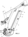
Fig. 2 is a perspective view of a frame assembly of the e-bike ofFig. 1 with a downtube removed so as to reveal a battery of the e-bike. -
Fig. 3 is a bottom perspective view of the battery ofFig. 2 . -
Fig. 4 is a top perspective view of the battery ofFig. 2 . -
Fig. 5 is an enlarged perspective view of a portion of the battery ofFig. 2 . -
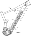
Fig. 6 is a cross-sectional view of a portion of the e-bike ofFig. 1 . -
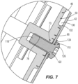
Fig. 7 is an enlarged portion of the cross-sectional view ofFig. 6 . - According to the invention, there is an e-bike according to claim 5.
- The e-bike includes a frame assembly having a frame member with an open end, wheels supporting the frame assembly, a motor assembly coupled to the frame assembly, and a battery positioned at least partially in the frame member. The battery includes a battery housing having an engagement feature integral with the battery housing and accessible from the open end of the frame member to facilitate removal of the battery from the frame member.
- The engagement feature can be configured to receive a tool to facilitate removal of the battery from the frame member. The tool can include a hook-shaped tool. The engagement feature can be integrated with the battery housing as one piece, and the engagement feature can be immovable relative to the battery housing. The frame member can include a downtube, and the open end can include a lower end of the downtube.
- According to the invention there is a battery according to claim 1.
- Other elements of the invention will become apparent by consideration of the detailed description and drawings.
- Before the e-bike and battery are explained in detail, it is to be understood that the invention is not limited in its application to the details of construction and the arrangement of components set forth in the following description or illustrated in the following drawings. The invention is defined by the scope of the appended claims.
- Referring to the drawings,
Fig. 1 is a perspective view of an electric bicycle ("e-bike") 10, according to the invention.E-bike 10 can comprise a pedal-assist e-bike and/or a power-on-demand e-bike. E-bike 10 can also comprise a pedal-assist e-bike and not a power-on-demand e-bike, or vice versa. - As illustrated in
Fig. 1 , thee-bike 10 includes aframe assembly 14, afirst wheel 18 coupled to and supporting theframe assembly 14, and asecond wheel 22 coupled to and supporting theframe assembly 14. Thee-bike 10 also includes amotor assembly 26 coupled to theframe assembly 14. Themotor assembly 26 can be operable to provide motive power to thee-bike 10. For example, themotor assembly 26 can be configured to generate motive power from electricity supplied to themotor assembly 26 by a battery 46 (Fig. 2 ), and can supply the motive power to a drivetrain of thee-bike 10. As illustrated inFig. 1 , themotor assembly 26 can be located generally at a lower portion of theframe assembly 14 and thee-bike 10, although themotor assembly 26 can be located elsewhere at theframe assembly 14 and thee-bike 10. - The
motor assembly 26 can include amotor output shaft 30. Further, themotor output shaft 30 can be configured to revolve in order to provide motive power to thee-bike 10. For example, themotor output shaft 30 can turn a sprocket of a drivetrain ofe-bike 10. - As illustrated in
FIG. 1 , themotor output shaft 30 can extend laterally away from thee-bike 10 on adrive side 34 of thee-bike 10. Thedrive side 34 can be located opposite anondrive side 38 of thee-bike 10. As illustrated inFig. 1 , themotor output shaft 30 can be splined, and can be coupled, for example, to a sprocket (e.g., via a spider) or other component of thee-bike 10. However, differentmotor output shafts 30 can be implemented. - As illustrated in
Fig. 2 , thee-bike 10 includes abattery 46. As discussed further herein, thebattery 46 is coupled (e.g., permanently or removably coupled) to theframe assembly 14 by one or more fasteners. Further, thebattery 46 can be electrically coupled (e.g., via electrical cables) to themotor assembly 26 to provide electricity to themotor assembly 26. Thebattery 46 also may provide electricity to one or more other components of the e-bike 10 (e.g., lights, navigation, sensors, etc.). - The
battery 46 is insertable (e.g., at least partially or fully insertable) into theframe assembly 14. For example, thebattery 46 can be insertable (e.g., at least partially or fully insertable) into a frame member (e.g., a tube) of theframe assembly 14, such as, for example, into a cavity within theframe assembly 14 or the frame member of theframe assembly 14. Thebattery 46 can be concealed (e.g., at least partially or fully) when thebattery 46 is inserted and fully installed into the frame assembly 14 (e.g., the frame member of the frame assembly 14). - Referring to
Figs. 1 and2 , theframe assembly 14 can include a downtube 42 (Fig. 1 ). Thedowntube 42 can extend up and/or away from themotor assembly 26. As illustrated inFig. 2 , thebattery 46 can be insertable (e.g., at least partially or fully) into thedowntube 42. As illustrated infigure 2 , thebattery 46 is entirely concealed and enclosed within thedowntube 42 when fully installed, and is coupled (e.g., via electrical cables) to themotor assembly 26 to provide electricity to themotor assembly 26. Thebattery 46 may instead be only partially concealed and enclosed within thedowntube 42 when fully installed. Meanwhile, although thebattery 46 is illustrated infigure 2 as being inserted into thedowntube 42, as discussed previously, thebattery 42 can be insertable into a different frame member of the frame assembly 14 (e.g., a top tube, a seat tube, etc.). - Referring now to
Figs. 2-7 , thebattery 46 includes abattery housing 50. Thebattery housing 50 can include afirst end 54 and asecond end 58 opposite thefirst end 54. Thebattery housing 50 further can include a first side 62 (e.g., a planar bottom side, as shown inFigs. 2 and3 ) disposed between thefirst end 54 and thesecond end 58, and an opposite, second side 66 (e.g., a planar upper side, as shown inFig. 4 ) disposed between thefirst end 54 and thesecond end 58. Thebattery housing 50 and thebattery 46 overall may be of different shapes and sizes than that illustrated. Thebattery housing 50 may be made of metal, plastic, and/or other suitable materials. - The
battery 46 includes one or more battery mounts. The battery mount(s) are located at one or more sides of thebattery housing 50, and optionally, only at one or more sides of thebattery housing 50. Two or more of the battery mount(s) can be similar or identical to each other. As discussed in more detail herein, the battery mount(s) are configured to receive one or more fasteners (e.g., bolts) to couple thebattery 46 to frameassembly 14. Thebattery 46 can be coupled to theframe assembly 14 by an interference fit. - As illustrated at
Fig. 3 , thebattery 46 includes afirst battery mount 70 and/or asecond battery mount 74 located along thefirst side 62 of thebattery housing 50. Thefirst battery mount 70 can be nearer to thefirst end 54 than to thesecond end 58, spaced from thefirst end 54, and/or disposed between thefirst end 54 and thesecond battery mount 74; and/or thesecond battery mount 74 can be nearer to thesecond end 58 than to thefirst end 54, spaced from thesecond end 58, and/or disposed between thefirst battery mount 70 and thesecond end 58. - The battery mount(s) of the
battery housing 50 each can include a metal insert that extends into thebattery housing 50 and that have a threaded aperture, which may be configured to receive a fastener as further discussed herein. For example, as illustrated atFig. 3 , thefirst battery mount 70 can include a metal insert that extends into thebattery housing 50 and has a first threadedaperture 78, and/or thesecond battery mount 74 can include a metal insert that extends into thebattery housing 50 and has a second threadedaperture 82. Alternatively, thefirst battery mount 70 and/or thesecond battery mount 74 may include threaded protrusions, or other-shaped threaded apertures than that illustrated, or apertures or protrusions that do not include threads. - The
battery 46 includes one or more resilient pads at an outer surface of thebattery housing 50. The resilient pad(s) can be located at one or more sides and/or corners of thebattery housing 50, or only at one or more sides or corners of thebattery housing 50. Two or more of the resilient pad(s) can be similar or identical to each other. One or more of the resilient pad(s) is located adjacent to (e.g., next to, directly abutting or flush with, or within a limited distance from, such as, for example, 1 millimeter, 2 millimeters, 4 millimeters, 8 millimeters, 16 millimeters, or 32 millimeters) one or more of the battery mount(s). Each one of the resilient pad(s) can be located adjacent to a different one of the battery mount(s). - As illustrated at
Figs. 3 and5 , thebattery 46 includes a firstresilient pad 86 and/or a secondresilient pad 90. The firstresilient pad 86 is located adjacent to (e.g., next to, directly abutting or flush with, or within a limited distance from, such as, for example, 1 millimeter, 2 millimeters, 4 millimeters, 8 millimeters, 16 millimeters, or 32 millimeters) thefirst battery mount 70; and/or the secondresilient pad 90 is located adjacent to (e.g., next to, directly abutting or flush with, or within a limited distance from, such as, for example, 1 millimeter, 2 millimeters, 4 millimeters, 8 millimeters, 16 millimeters, or 32 millimeters) thesecond battery mount 74. The secondresilient pad 90 can be similar or identical to the firstresilient pad 86. - The first
resilient pad 86 comprises a generally thin, circular, disk-shaped pad defining a firstcentral opening 94. The firstresilient pad 86 and/or the firstcentral opening 94 can alternatively have a non-circular shape, and/or a shape other than a disk (e.g., a more rounded shape, or a shape having concave and/or convex surfaces). The firstresilient pad 86 completely surrounds and is concentric about thefirst battery mount 70 at an outer surface of thebattery 46 and/or thebattery housing 50. The firstresilient pad 86 can also only partially surround (e.g., substantially surround) thefirst battery mount 70, and/or can be non-concentric about thefirst battery mount 70. The firstresilient pad 86 is made of an elastic or other resilient material (e.g., rubber). The resilient material is more resilient than a material of thebattery housing 50. - The second
resilient pad 90 comprises a generally thin, circular, disk-shaped pad defining a secondcentral opening 98 in a middle of the pad. The secondresilient pad 90 and/or the secondcentral opening 98 can alternatively have a non-circular shape, and/or a shape other than a disk (e.g., a more rounded shape, or a shape having concave and/or convex surfaces). The secondresilient pad 90 completely surrounds and is concentric about thesecond battery mount 74 at the outer surface of thebattery 46 and/or thebattery housing 50. Alternatively, the secondresilient pad 90 can only partially surround (e.g., substantially surround) thesecond battery mount 74, and/or be non-concentric about thesecond battery mount 74. The secondresilient pad 90 is made of an elastic or other resilient material (e.g., rubber). The resilient material is more resilient than a material of thebattery housing 50. - The first
resilient pad 86 and the secondresilient pad 90 are formed with the battery housing 50 (e.g., co-molded). As illustrated atFig. 3 , the firstresilient pad 86 and the secondresilient pad 90 are positioned along a common side (e.g., the first side 62) of thebattery housing 50, and not along any other sides or portions of thebattery housing 50. For example, as illustrated, thebattery 46 does not include resilient pads along thesecond side 66, or along any corners of thebattery housing 50. Alternatively, thebattery 46 may include resilient pads along multiple sides or locations (e.g., along both thefirst side 62 and thesecond side 66, and/or along corners of the battery 46). - The first
central opening 94 and/or the secondcentral opening 98 have a diameter of from 9 millimeters - 13 millimeters, and the first threadedaperture 78 and/or the second threadedaperture 82 have a diameter of from 4 millimeters - 6 millimeters. The firstresilient pad 86 and/or the secondresilient pad 90 have an outer diameter of from 35 millimeters - 45 millimeters, and/or have a thickness of from 1 millimeter - 3 millimeters. The firstresilient pad 86 and/or the secondresilient pad 90 have a combined surface area that is less than a surface area of the remainder offirst side 62, although, the resilient pads on thefirst side 62 may alternatively have a combined surface area that is greater than a remainder of the surface area of thefirst side 62. The first and second resilient pads and openings may include different values and ranges of values than that illustrated. - The
battery housing 50 includes one or more projecting lips. The projecting lip(s) of thebattery housing 50 surround (e.g., partially or fully, discontinuously or continuously surround) the resilient pad(s) of thebattery 46, and can optionally also be located adjacent to (e.g., next to, directly abutting or flush with, or within a limited distance from, such as, for example, 1 millimeter, 2 millimeters, 4 millimeters, 8 millimeters, 16 millimeters, or 32 millimeters), the resilient pad(s) of thebattery 46. Two or more of the projecting lip(s) can be similar or identical to each other. - For example, as illustrated at
Figs. 3 and5 , thebattery housing 50 can include a first projectinglip 102 that circles entirely around the firstresilient pad 86, and a second projectinglip 106 that circles entirely around the secondresilient pad 90. - The e-bike 10 includes one or more fasteners (e.g., bolts, screws, etc.). The fastener(s) of the e-bike 10 can be received at and coupled to the battery mount(s) of the
battery housing 50 in order to couple thebattery 46 to theframe assembly 14. Two or more of the fastener(s) can be similar or identical to each other. - For example, as illustrated at
Figs. 6 and7 , the e-bike 10 can include a first fastener 110 (e.g., bolt) and/or a second fastener 114 (e.g., bolt) that couple theframe assembly 14 to the battery 46 (e.g., to the battery mounts 70, 74, respectively). As illustrated inFig. 7 , abody 118 of thefirst fastener 110 may be inserted through anopening 122 of thedowntube 42, with ahead 126 of thefastener 110 remaining outside thedowntube 42. Awasher 124 also may be provided. Thefastener 110 is threaded into the first battery mount 70 (i.e., into the first threaded aperture 78), until the firstresilient pad 86 is pulled tightly up against an interior surface of thedowntube 42 and compresses between thebattery housing 50 and the interior surface of thedowntube 42. Similarly, thesecond fastener 114 also may be tightened, so as to compress the secondresilient pad 90 between thebattery housing 50 and the interior surface of thedowntube 42. This tightening and compression can secure thebattery housing 50 in close proximity to thedowntube 42, while still leaving aslight gap 130 between thebattery housing 50 and the interior surface of thedowntube 42. Thus thebattery housing 50 does not contact the frame assembly 14 (FIG. 1 ) and/or thedowntube 42. Rather, only the compressed first and secondresilient pads downtube 42 when thebattery 46 has been fully installed. Alternatively the e-bike may includedifferent fasteners 110, 114 (e.g., screws, etc.) than that illustrated. - The
battery 46 can be sized and/or shaped to be smaller than an inside volume of thedowntube 42 such that when thebattery 46 is initially installed (prior to compressing the first and secondresilient pads 86, 90), thesecond side 66 of thebattery 46 is not in contact with thedowntube 42. The size of thebattery 46, as well as the location of the first and secondresilient pads battery 46 during installation, while also reducing friction to facilitate removal of thebattery 46. - The
battery 46 can include an engagement feature. The engagement feature can facilitate insertion and/or removal of thebattery 46 from theframe assembly 14, such as, for example, through an opening in theframe assembly 14. Alternatively the engagement feature can be omitted. - For example, as illustrated at
Figs. 5 and6 , thebattery 46 can include anengagement feature 134. Theengagement feature 134 can be accessible from a lower,open end 138 of thedowntube 42 to facilitate insertion and/or removal of thebattery 46 from thedowntube 42. Theengagement feature 134 can be integrated with thebattery housing 50 as one piece (e.g., formed together or co-molded), can be immovable relative to the battery housing 50 (i.e., is fixed in place), and/or can be an eyelet sized and shaped to receive a tool (e.g., a hook-shaped tool) that may be used to pull thebattery 46 from (or insert thebattery 46 into) the lower,open end 138 of thedowntube 42, such as, for example, when themotor assembly 26 has been removed or thedowntube 42 is otherwise opened. The tool may be sized to be small enough to enter the lower,open end 138 of thedowntube 42. When thebattery 46 is fully installed within thedowntube 42, theengagement feature 134 may be located adjacent to and/or closer to the lower,open end 138 of thedowntube 42 than to an opposite,closed end 142 of thedowntube 42. - The
engagement feature 134 can be separately coupled to the battery housing 50 (e.g., via a fastener). Theengagement feature 134 can be movable relative to the battery housing 50 (e.g., can rotate about one or more axes). Theengagement feature 134 may have a size and/or shape other than that illustrated, or may be a feature other than an eyelet (e.g., a hook, protruding ledge, or any other feature that facilitates grasping and pulling of thebattery 46 via a tool). Theengagement feature 134 may be used, for example, to pull thebattery 46 out of thedowntube 42 when thebattery 46 is otherwise stuck (e.g., if cables have wedged between thedowntube 42 and the battery 46). - Various features of the invention are set forth in the following claims.
- When used in this specification and claims, the terms "comprises" and "comprising" and variations thereof mean that the specified features, steps or integers are included. The terms are not to be interpreted to exclude the presence of other features, steps or components.
Claims (13)
- An e-bike battery (46) configured to be inserted into and coupled to an e-bike frame assembly (14) of an e-bike (10), the e-bike battery (46) comprising:a battery housing (50);a battery mount (70, 74) located along a side of the battery housing (50), wherein the battery mount (70, 74) defines an aperture (78, 82) configured to receive a fastener (110, 114);characterized in that a resilient pad (86, 90) is located adjacent the battery mount (70, 74) and at an outer surface of the battery housing (50), wherein the resilient pad (86, 90) extends at least partially around the aperture (78, 82), and is configured to be compressed between the battery housing (50) and the e-bike frame assembly (14) when the e-bike battery (46) is coupled to the e-bike frame assembly (14) with the fastener (110, 114),wherein the resilient pad (86, 90) is formed with the battery housing (50) and the battery housing (50) includes a housing material that is less resilient than a pad material of the resilient pad (86, 90), andwherein the battery housing (50) includes a projecting lip (102, 106) which surrounds at least partially the resilient pad (86, 90).
- The e-bike battery (46) of claim 1, wherein the resilient pad (86, 90) is a generally thin, circular, disk-shaped pad defining a central opening (94, 98).
- The e-bike battery (46) of claim 1 or claim 2, wherein:the battery mount (70, 74) is a first battery mount (70);the e-bike battery (46) further includes a second battery mount (74) spaced apart from the first battery mount;the resilient pad (86, 90) is a first resilient pad (86) adjacent the first battery mount (70); andthe e-bike battery (46) further includes a second resilient pad (90) adjacent the second battery mount (74).
- The e-bike battery (46) of any one of claims 1-3, further comprising an engagement feature (134) adjacent one end (54, 58) of the e-bike battery (46) to facilitate removal of the e-bike battery (46) from the e-bike frame assembly (14), wherein the engagement feature (134) is configured to receive a tool to facilitate removal of the e-bike battery (46) from the e-bike frame assembly (14).
- An e-bike (10) comprising:a frame assembly (14);a first wheel (18) supporting the frame assembly (14) and a second wheel (22) supporting the frame assembly;a motor assembly (26) coupled to the frame assembly (14);the e-bike battery (46) of claim 1;a fastener (110, 114) coupling the frame assembly to the battery mount (70, 74) of the e-bike battery (46); andwherein the resilient pad (86, 90) is compressed between the frame assembly (14) and the battery housing (50).
- The e-bike (10) of claim 5, wherein the aperture (78, 82) of the battery mount (70, 74) is a threaded aperture, and wherein the fastener (110, 114) extends through the frame assembly (14) and into the threaded aperture (78, 82) to couple the frame assembly (14) to the battery mount (70, 74) .
- The e-bike (10) of claim 6, wherein the resilient pad (86, 90) completely surrounds the battery mount (70, 74).
- The e-bike (10) of any one of claims 5-7, wherein:the battery mount (70, 74) is a first battery mount (70);the battery (46) further includes a second battery mount (74) spaced apart from the first battery mount (70);the resilient pad (86, 90) is a first resilient pad (86) adjacent the first battery mount (70); andthe e-bike further includes a second resilient pad (90) adjacent the second battery mount (74).
- The e-bike (10) of claim 8, wherein the second resilient pad (90) at least partially surrounds the second battery mount (74).
- The e-bike (10) of claim 9, wherein the first resilient pad (86) completely surrounds the first battery mount (70) and the second resilient pad (90) completely surrounds the second battery mount (74).
- The e-bike (10) of any one of claims 8-10, wherein the first resilient pad (86) and the second resilient pad (90) are each positioned along a common side of the battery housing (50).
- The e-bike (10) of claim 11, wherein only the common side of the battery housing (50) includes resilient pads (86, 90) positioned along the battery housing (50).
- The e-bike (10) of any one of claims 8-12, wherein:the battery (46) includes a first end (54) and a second end (58) opposite the first end; andthe first resilient pad (86) and the second resilient pad (90) each are spaced away from both the first end (54) and the second end (58).
Applications Claiming Priority (1)
| Application Number | Priority Date | Filing Date | Title |
|---|---|---|---|
| US16/448,855 US11345437B2 (en) | 2019-06-21 | 2019-06-21 | Battery for electric bicycle |
Publications (2)
| Publication Number | Publication Date |
|---|---|
| EP3753828A1 EP3753828A1 (en) | 2020-12-23 |
| EP3753828B1 true EP3753828B1 (en) | 2024-05-08 |
Family
ID=71108409
Family Applications (1)
| Application Number | Title | Priority Date | Filing Date |
|---|---|---|---|
| EP20180678.3A Active EP3753828B1 (en) | 2019-06-21 | 2020-06-18 | Battery for electric bicycle |
Country Status (2)
| Country | Link |
|---|---|
| US (1) | US11345437B2 (en) |
| EP (1) | EP3753828B1 (en) |
Families Citing this family (17)
| Publication number | Priority date | Publication date | Assignee | Title |
|---|---|---|---|---|
| US10730584B2 (en) | 2014-09-11 | 2020-08-04 | Stacyc, Inc. | Convertible motorized running cycle |
| DE102019213426A1 (en) * | 2019-09-04 | 2021-03-04 | Robert Bosch Gmbh | Holding device for releasably holding an energy storage device on a frame unit and bicycle frame |
| US11639211B2 (en) * | 2019-11-19 | 2023-05-02 | Paul Michael Farrell | Bicycle frame for an e-bike |
| JP7554596B2 (en) * | 2020-07-31 | 2024-09-20 | 株式会社シマノ | Battery holding device for human-powered vehicle, drive unit for human-powered vehicle, and battery unit for human-powered vehicle |
| DE202020105635U1 (en) * | 2020-10-01 | 2022-01-07 | Canyon Bicycles Gmbh | bicycle frame tube |
| DE202020105638U1 (en) * | 2020-10-01 | 2022-02-17 | Canyon Bicycles Gmbh | bicycle frame tube |
| US11603165B2 (en) * | 2021-03-04 | 2023-03-14 | StaCyc, LLC | Bike frame having a drive module enclosure |
| KR102534278B1 (en) * | 2021-05-03 | 2023-05-26 | 삼천리자전거 주식회사 | Controller for multi battery and bicycle having the same |
| CN113734329B (en) * | 2021-09-23 | 2022-09-20 | 杭州通普机电科技有限公司 | Multifunctional foldable electric bicycle |
| USD1022804S1 (en) | 2021-12-13 | 2024-04-16 | StaCyc, LLC | Electric bicycle |
| US11850969B1 (en) | 2022-08-23 | 2023-12-26 | Intercontinental Mobility Company | Portable motorized vehicles |
| DE102022127802A1 (en) * | 2022-10-20 | 2024-04-25 | Sram Deutschland Gmbh | Electric bicycle drive unit and bicycle frame, frame interface unit and energy storage device for electric bicycle drive unit |
| USD1066141S1 (en) * | 2022-12-26 | 2025-03-11 | Jiangsu Jiumo Technology Co., Ltd. | Electric bicycle |
| US12565277B2 (en) | 2023-02-09 | 2026-03-03 | StaCyc, LLC | Battery support frame for a bicycle |
| USD1038842S1 (en) * | 2023-03-15 | 2024-08-13 | Zhejiang Apollo Sports Technology Co., Ltd. | Motorcycle |
| USD1042236S1 (en) * | 2023-05-10 | 2024-09-17 | Haimiwei Intelligent Technology (Shanghai) Co., Ltd. | Bicycle frame |
| CN116653640A (en) * | 2023-06-26 | 2023-08-29 | 东风商用车有限公司 | Suspension device and frame assembly of double-stack fuel cell |
Citations (2)
| Publication number | Priority date | Publication date | Assignee | Title |
|---|---|---|---|---|
| DE102016010338A1 (en) * | 2016-08-29 | 2018-03-01 | BMZ GmbH | Device for energy storage and / or energy emission and method for using a device for energy storage and / or energy emission |
| DE102018211464A1 (en) * | 2018-07-11 | 2019-05-23 | Robert Bosch Gmbh | Upholstery element for an energy storage |
Family Cites Families (12)
| Publication number | Priority date | Publication date | Assignee | Title |
|---|---|---|---|---|
| GB401359A (en) | 1932-05-13 | 1933-11-13 | Lucas Ltd Joseph | Improvements in or relating to cases for electric batteries or holders therefor |
| JPH10181651A (en) | 1996-12-26 | 1998-07-07 | Yamaha Motor Co Ltd | Electric bicycle battery box fixing structure |
| TW490418B (en) | 1999-10-13 | 2002-06-11 | Honda Motor Co Ltd | Battery mounting and removing apparatus for power-assisted bicycle and wheel-lock apparatus |
| CN102082309B (en) | 2009-11-27 | 2014-09-17 | 尹学军 | Method for quickly supplementing electric energy of electric vehicle and power supply unit thereof |
| DE102010005222A1 (en) | 2010-01-21 | 2011-07-28 | Schaeffler Technologies GmbH & Co. KG, 91074 | Power supply unit for use in car, has frame held into stared confinement that defines holding area by multiple elastic connections, and exhibiting defined spacing to stared confinement when supply unit is supported in holding area |
| JP2011235749A (en) * | 2010-05-10 | 2011-11-24 | Makita Corp | Electric vehicle using battery pack as power source |
| US9954206B2 (en) * | 2013-12-27 | 2018-04-24 | King Products, LLC | Battery holder and isolation assembly |
| US9580141B2 (en) | 2015-06-26 | 2017-02-28 | Specialized Bicycle Components, Inc. | Bicycle frame with improved battery mount |
| US10518841B2 (en) * | 2015-06-26 | 2019-12-31 | Specialized Bicycle Components, Inc. | Ebike battery mount |
| PL3281855T3 (en) * | 2016-08-10 | 2020-08-24 | BH Bikes Europe, S.L. | Electric bicycle frame and electric bicycle |
| JP6731368B2 (en) | 2017-03-17 | 2020-07-29 | 株式会社シマノ | Bicycle battery unit |
| US12027717B2 (en) * | 2019-10-10 | 2024-07-02 | Megaware Keelguard Reacquisition, Llc | Customizable support pad for reducing vibration and gravitational shock acting on a battery |
-
2019
- 2019-06-21 US US16/448,855 patent/US11345437B2/en active Active
-
2020
- 2020-06-18 EP EP20180678.3A patent/EP3753828B1/en active Active
Patent Citations (2)
| Publication number | Priority date | Publication date | Assignee | Title |
|---|---|---|---|---|
| DE102016010338A1 (en) * | 2016-08-29 | 2018-03-01 | BMZ GmbH | Device for energy storage and / or energy emission and method for using a device for energy storage and / or energy emission |
| DE102018211464A1 (en) * | 2018-07-11 | 2019-05-23 | Robert Bosch Gmbh | Upholstery element for an energy storage |
Also Published As
| Publication number | Publication date |
|---|---|
| US11345437B2 (en) | 2022-05-31 |
| US20200398931A1 (en) | 2020-12-24 |
| EP3753828A1 (en) | 2020-12-23 |
Similar Documents
| Publication | Publication Date | Title |
|---|---|---|
| EP3753828B1 (en) | Battery for electric bicycle | |
| CN217062344U (en) | Mounting mechanism, battery pack assembly and vehicle | |
| JP3217960U (en) | Solar panel support rack mounted on the vehicle roof | |
| JP5849720B2 (en) | Battery pack water injection structure | |
| CN110350118A (en) | Traction battery shell clamping device and fastening method | |
| JP2019133867A (en) | Battery assembly structure | |
| KR102684808B1 (en) | Battery Pack with a handle which has a loose stopper | |
| CN217022207U (en) | Installing support and car of charging seat fill soon or slowly | |
| US20250135916A1 (en) | Overmolded mechanical fastener with integrated sealing | |
| CN110034251A (en) | Power battery pack maintenance control panel | |
| CN210110884U (en) | Battery pack box, battery pack and vehicle | |
| JP2024541871A (en) | Battery Packs and Electrical Devices | |
| US9849795B2 (en) | Connector attachment structure for electric vehicle | |
| CN216916011U (en) | Vehicle chassis and vehicle | |
| EP4425659A1 (en) | Battery pack and electric device | |
| CN109050234B (en) | Power battery package fixing device and car | |
| CN215155256U (en) | Battery compartment components and electric scooters | |
| JP2011245911A (en) | Fixation structure for rear wiper device | |
| EP3981681B1 (en) | Swingarm fixing hanger | |
| JPH08241730A (en) | Rechargeable battery | |
| CN221541799U (en) | External member and installation device for installing electric vehicle unlocking sensor | |
| JP4391635B2 (en) | Power unit for electric bicycle | |
| CN223990076U (en) | Spare tire mounting device and vehicle | |
| CN222146476U (en) | A locking structure, a battery compartment module and a mobile robot | |
| US20250269759A1 (en) | Replaceable battery fixing structure |
Legal Events
| Date | Code | Title | Description |
|---|---|---|---|
| PUAI | Public reference made under article 153(3) epc to a published international application that has entered the european phase |
Free format text: ORIGINAL CODE: 0009012 |
|
| STAA | Information on the status of an ep patent application or granted ep patent |
Free format text: STATUS: THE APPLICATION HAS BEEN PUBLISHED |
|
| AK | Designated contracting states |
Kind code of ref document: A1 Designated state(s): AL AT BE BG CH CY CZ DE DK EE ES FI FR GB GR HR HU IE IS IT LI LT LU LV MC MK MT NL NO PL PT RO RS SE SI SK SM TR |
|
| AX | Request for extension of the european patent |
Extension state: BA ME |
|
| STAA | Information on the status of an ep patent application or granted ep patent |
Free format text: STATUS: REQUEST FOR EXAMINATION WAS MADE |
|
| 17P | Request for examination filed |
Effective date: 20210623 |
|
| RBV | Designated contracting states (corrected) |
Designated state(s): AL AT BE BG CH CY CZ DE DK EE ES FI FR GB GR HR HU IE IS IT LI LT LU LV MC MK MT NL NO PL PT RO RS SE SI SK SM TR |
|
| STAA | Information on the status of an ep patent application or granted ep patent |
Free format text: STATUS: EXAMINATION IS IN PROGRESS |
|
| 17Q | First examination report despatched |
Effective date: 20211004 |
|
| RIC1 | Information provided on ipc code assigned before grant |
Ipc: B62K 19/34 20060101ALN20230213BHEP Ipc: B62M 6/55 20100101ALN20230213BHEP Ipc: H01M 50/249 20210101ALI20230213BHEP Ipc: B60L 50/64 20190101ALI20230213BHEP Ipc: B62K 19/40 20060101ALI20230213BHEP Ipc: B62M 6/90 20100101ALI20230213BHEP Ipc: B62J 43/28 20200101ALI20230213BHEP Ipc: B62J 43/13 20200101AFI20230213BHEP |
|
| GRAP | Despatch of communication of intention to grant a patent |
Free format text: ORIGINAL CODE: EPIDOSNIGR1 |
|
| STAA | Information on the status of an ep patent application or granted ep patent |
Free format text: STATUS: GRANT OF PATENT IS INTENDED |
|
| RIC1 | Information provided on ipc code assigned before grant |
Ipc: B62K 19/34 20060101ALN20231110BHEP Ipc: B62M 6/55 20100101ALN20231110BHEP Ipc: H01M 50/249 20210101ALI20231110BHEP Ipc: B60L 50/64 20190101ALI20231110BHEP Ipc: B62K 19/40 20060101ALI20231110BHEP Ipc: B62M 6/90 20100101ALI20231110BHEP Ipc: B62J 43/28 20200101ALI20231110BHEP Ipc: B62J 43/13 20200101AFI20231110BHEP |
|
| INTG | Intention to grant announced |
Effective date: 20231129 |
|
| GRAS | Grant fee paid |
Free format text: ORIGINAL CODE: EPIDOSNIGR3 |
|
| GRAA | (expected) grant |
Free format text: ORIGINAL CODE: 0009210 |
|
| STAA | Information on the status of an ep patent application or granted ep patent |
Free format text: STATUS: THE PATENT HAS BEEN GRANTED |
|
| AK | Designated contracting states |
Kind code of ref document: B1 Designated state(s): AL AT BE BG CH CY CZ DE DK EE ES FI FR GB GR HR HU IE IS IT LI LT LU LV MC MK MT NL NO PL PT RO RS SE SI SK SM TR |
|
| REG | Reference to a national code |
Ref country code: GB Ref legal event code: FG4D |
|
| REG | Reference to a national code |
Ref country code: CH Ref legal event code: EP |
|
| REG | Reference to a national code |
Ref country code: DE Ref legal event code: R096 Ref document number: 602020030507 Country of ref document: DE |
|
| REG | Reference to a national code |
Ref country code: IE Ref legal event code: FG4D |
|
| REG | Reference to a national code |
Ref country code: LT Ref legal event code: MG9D |
|
| REG | Reference to a national code |
Ref country code: NL Ref legal event code: MP Effective date: 20240508 |
|
| PG25 | Lapsed in a contracting state [announced via postgrant information from national office to epo] |
Ref country code: IS Free format text: LAPSE BECAUSE OF FAILURE TO SUBMIT A TRANSLATION OF THE DESCRIPTION OR TO PAY THE FEE WITHIN THE PRESCRIBED TIME-LIMIT Effective date: 20240908 |
|
| PG25 | Lapsed in a contracting state [announced via postgrant information from national office to epo] |
Ref country code: BG Free format text: LAPSE BECAUSE OF FAILURE TO SUBMIT A TRANSLATION OF THE DESCRIPTION OR TO PAY THE FEE WITHIN THE PRESCRIBED TIME-LIMIT Effective date: 20240508 |
|
| PG25 | Lapsed in a contracting state [announced via postgrant information from national office to epo] |
Ref country code: FI Free format text: LAPSE BECAUSE OF FAILURE TO SUBMIT A TRANSLATION OF THE DESCRIPTION OR TO PAY THE FEE WITHIN THE PRESCRIBED TIME-LIMIT Effective date: 20240508 Ref country code: HR Free format text: LAPSE BECAUSE OF FAILURE TO SUBMIT A TRANSLATION OF THE DESCRIPTION OR TO PAY THE FEE WITHIN THE PRESCRIBED TIME-LIMIT Effective date: 20240508 |
|
| PG25 | Lapsed in a contracting state [announced via postgrant information from national office to epo] |
Ref country code: GR Free format text: LAPSE BECAUSE OF FAILURE TO SUBMIT A TRANSLATION OF THE DESCRIPTION OR TO PAY THE FEE WITHIN THE PRESCRIBED TIME-LIMIT Effective date: 20240809 |
|
| PG25 | Lapsed in a contracting state [announced via postgrant information from national office to epo] |
Ref country code: PT Free format text: LAPSE BECAUSE OF FAILURE TO SUBMIT A TRANSLATION OF THE DESCRIPTION OR TO PAY THE FEE WITHIN THE PRESCRIBED TIME-LIMIT Effective date: 20240909 |
|
| REG | Reference to a national code |
Ref country code: AT Ref legal event code: MK05 Ref document number: 1684791 Country of ref document: AT Kind code of ref document: T Effective date: 20240508 |
|
| PG25 | Lapsed in a contracting state [announced via postgrant information from national office to epo] |
Ref country code: NL Free format text: LAPSE BECAUSE OF FAILURE TO SUBMIT A TRANSLATION OF THE DESCRIPTION OR TO PAY THE FEE WITHIN THE PRESCRIBED TIME-LIMIT Effective date: 20240508 |
|
| PG25 | Lapsed in a contracting state [announced via postgrant information from national office to epo] |
Ref country code: ES Free format text: LAPSE BECAUSE OF FAILURE TO SUBMIT A TRANSLATION OF THE DESCRIPTION OR TO PAY THE FEE WITHIN THE PRESCRIBED TIME-LIMIT Effective date: 20240508 |
|
| PG25 | Lapsed in a contracting state [announced via postgrant information from national office to epo] |
Ref country code: AT Free format text: LAPSE BECAUSE OF FAILURE TO SUBMIT A TRANSLATION OF THE DESCRIPTION OR TO PAY THE FEE WITHIN THE PRESCRIBED TIME-LIMIT Effective date: 20240508 |
|
| PG25 | Lapsed in a contracting state [announced via postgrant information from national office to epo] |
Ref country code: PL Free format text: LAPSE BECAUSE OF FAILURE TO SUBMIT A TRANSLATION OF THE DESCRIPTION OR TO PAY THE FEE WITHIN THE PRESCRIBED TIME-LIMIT Effective date: 20240508 |
|
| PG25 | Lapsed in a contracting state [announced via postgrant information from national office to epo] |
Ref country code: LV Free format text: LAPSE BECAUSE OF FAILURE TO SUBMIT A TRANSLATION OF THE DESCRIPTION OR TO PAY THE FEE WITHIN THE PRESCRIBED TIME-LIMIT Effective date: 20240508 |
|
| PG25 | Lapsed in a contracting state [announced via postgrant information from national office to epo] |
Ref country code: PT Free format text: LAPSE BECAUSE OF FAILURE TO SUBMIT A TRANSLATION OF THE DESCRIPTION OR TO PAY THE FEE WITHIN THE PRESCRIBED TIME-LIMIT Effective date: 20240909 Ref country code: PL Free format text: LAPSE BECAUSE OF FAILURE TO SUBMIT A TRANSLATION OF THE DESCRIPTION OR TO PAY THE FEE WITHIN THE PRESCRIBED TIME-LIMIT Effective date: 20240508 Ref country code: NO Free format text: LAPSE BECAUSE OF FAILURE TO SUBMIT A TRANSLATION OF THE DESCRIPTION OR TO PAY THE FEE WITHIN THE PRESCRIBED TIME-LIMIT Effective date: 20240808 Ref country code: NL Free format text: LAPSE BECAUSE OF FAILURE TO SUBMIT A TRANSLATION OF THE DESCRIPTION OR TO PAY THE FEE WITHIN THE PRESCRIBED TIME-LIMIT Effective date: 20240508 Ref country code: LV Free format text: LAPSE BECAUSE OF FAILURE TO SUBMIT A TRANSLATION OF THE DESCRIPTION OR TO PAY THE FEE WITHIN THE PRESCRIBED TIME-LIMIT Effective date: 20240508 Ref country code: IS Free format text: LAPSE BECAUSE OF FAILURE TO SUBMIT A TRANSLATION OF THE DESCRIPTION OR TO PAY THE FEE WITHIN THE PRESCRIBED TIME-LIMIT Effective date: 20240908 Ref country code: HR Free format text: LAPSE BECAUSE OF FAILURE TO SUBMIT A TRANSLATION OF THE DESCRIPTION OR TO PAY THE FEE WITHIN THE PRESCRIBED TIME-LIMIT Effective date: 20240508 Ref country code: GR Free format text: LAPSE BECAUSE OF FAILURE TO SUBMIT A TRANSLATION OF THE DESCRIPTION OR TO PAY THE FEE WITHIN THE PRESCRIBED TIME-LIMIT Effective date: 20240809 Ref country code: FI Free format text: LAPSE BECAUSE OF FAILURE TO SUBMIT A TRANSLATION OF THE DESCRIPTION OR TO PAY THE FEE WITHIN THE PRESCRIBED TIME-LIMIT Effective date: 20240508 Ref country code: ES Free format text: LAPSE BECAUSE OF FAILURE TO SUBMIT A TRANSLATION OF THE DESCRIPTION OR TO PAY THE FEE WITHIN THE PRESCRIBED TIME-LIMIT Effective date: 20240508 Ref country code: BG Free format text: LAPSE BECAUSE OF FAILURE TO SUBMIT A TRANSLATION OF THE DESCRIPTION OR TO PAY THE FEE WITHIN THE PRESCRIBED TIME-LIMIT Effective date: 20240508 Ref country code: AT Free format text: LAPSE BECAUSE OF FAILURE TO SUBMIT A TRANSLATION OF THE DESCRIPTION OR TO PAY THE FEE WITHIN THE PRESCRIBED TIME-LIMIT Effective date: 20240508 Ref country code: RS Free format text: LAPSE BECAUSE OF FAILURE TO SUBMIT A TRANSLATION OF THE DESCRIPTION OR TO PAY THE FEE WITHIN THE PRESCRIBED TIME-LIMIT Effective date: 20240808 |
|
| PG25 | Lapsed in a contracting state [announced via postgrant information from national office to epo] |
Ref country code: DK Free format text: LAPSE BECAUSE OF FAILURE TO SUBMIT A TRANSLATION OF THE DESCRIPTION OR TO PAY THE FEE WITHIN THE PRESCRIBED TIME-LIMIT Effective date: 20240508 |
|
| PG25 | Lapsed in a contracting state [announced via postgrant information from national office to epo] |
Ref country code: EE Free format text: LAPSE BECAUSE OF FAILURE TO SUBMIT A TRANSLATION OF THE DESCRIPTION OR TO PAY THE FEE WITHIN THE PRESCRIBED TIME-LIMIT Effective date: 20240508 |
|
| PG25 | Lapsed in a contracting state [announced via postgrant information from national office to epo] |
Ref country code: CZ Free format text: LAPSE BECAUSE OF FAILURE TO SUBMIT A TRANSLATION OF THE DESCRIPTION OR TO PAY THE FEE WITHIN THE PRESCRIBED TIME-LIMIT Effective date: 20240508 |
|
| PG25 | Lapsed in a contracting state [announced via postgrant information from national office to epo] |
Ref country code: SK Free format text: LAPSE BECAUSE OF FAILURE TO SUBMIT A TRANSLATION OF THE DESCRIPTION OR TO PAY THE FEE WITHIN THE PRESCRIBED TIME-LIMIT Effective date: 20240508 Ref country code: RO Free format text: LAPSE BECAUSE OF FAILURE TO SUBMIT A TRANSLATION OF THE DESCRIPTION OR TO PAY THE FEE WITHIN THE PRESCRIBED TIME-LIMIT Effective date: 20240508 |
|
| PG25 | Lapsed in a contracting state [announced via postgrant information from national office to epo] |
Ref country code: SM Free format text: LAPSE BECAUSE OF FAILURE TO SUBMIT A TRANSLATION OF THE DESCRIPTION OR TO PAY THE FEE WITHIN THE PRESCRIBED TIME-LIMIT Effective date: 20240508 |
|
| PG25 | Lapsed in a contracting state [announced via postgrant information from national office to epo] |
Ref country code: SM Free format text: LAPSE BECAUSE OF FAILURE TO SUBMIT A TRANSLATION OF THE DESCRIPTION OR TO PAY THE FEE WITHIN THE PRESCRIBED TIME-LIMIT Effective date: 20240508 Ref country code: SK Free format text: LAPSE BECAUSE OF FAILURE TO SUBMIT A TRANSLATION OF THE DESCRIPTION OR TO PAY THE FEE WITHIN THE PRESCRIBED TIME-LIMIT Effective date: 20240508 Ref country code: RO Free format text: LAPSE BECAUSE OF FAILURE TO SUBMIT A TRANSLATION OF THE DESCRIPTION OR TO PAY THE FEE WITHIN THE PRESCRIBED TIME-LIMIT Effective date: 20240508 Ref country code: EE Free format text: LAPSE BECAUSE OF FAILURE TO SUBMIT A TRANSLATION OF THE DESCRIPTION OR TO PAY THE FEE WITHIN THE PRESCRIBED TIME-LIMIT Effective date: 20240508 Ref country code: DK Free format text: LAPSE BECAUSE OF FAILURE TO SUBMIT A TRANSLATION OF THE DESCRIPTION OR TO PAY THE FEE WITHIN THE PRESCRIBED TIME-LIMIT Effective date: 20240508 Ref country code: CZ Free format text: LAPSE BECAUSE OF FAILURE TO SUBMIT A TRANSLATION OF THE DESCRIPTION OR TO PAY THE FEE WITHIN THE PRESCRIBED TIME-LIMIT Effective date: 20240508 |
|
| REG | Reference to a national code |
Ref country code: CH Ref legal event code: PL |
|
| PG25 | Lapsed in a contracting state [announced via postgrant information from national office to epo] |
Ref country code: MC Free format text: LAPSE BECAUSE OF FAILURE TO SUBMIT A TRANSLATION OF THE DESCRIPTION OR TO PAY THE FEE WITHIN THE PRESCRIBED TIME-LIMIT Effective date: 20240508 Ref country code: IT Free format text: LAPSE BECAUSE OF FAILURE TO SUBMIT A TRANSLATION OF THE DESCRIPTION OR TO PAY THE FEE WITHIN THE PRESCRIBED TIME-LIMIT Effective date: 20240508 |
|
| REG | Reference to a national code |
Ref country code: DE Ref legal event code: R097 Ref document number: 602020030507 Country of ref document: DE |
|
| PG25 | Lapsed in a contracting state [announced via postgrant information from national office to epo] |
Ref country code: LU Free format text: LAPSE BECAUSE OF NON-PAYMENT OF DUE FEES Effective date: 20240618 |
|
| PLBE | No opposition filed within time limit |
Free format text: ORIGINAL CODE: 0009261 |
|
| STAA | Information on the status of an ep patent application or granted ep patent |
Free format text: STATUS: NO OPPOSITION FILED WITHIN TIME LIMIT |
|
| 26N | No opposition filed |
Effective date: 20250211 |
|
| PG25 | Lapsed in a contracting state [announced via postgrant information from national office to epo] |
Ref country code: IE Free format text: LAPSE BECAUSE OF NON-PAYMENT OF DUE FEES Effective date: 20240618 |
|
| GBPC | Gb: european patent ceased through non-payment of renewal fee |
Effective date: 20240808 |
|
| PG25 | Lapsed in a contracting state [announced via postgrant information from national office to epo] |
Ref country code: SI Free format text: LAPSE BECAUSE OF FAILURE TO SUBMIT A TRANSLATION OF THE DESCRIPTION OR TO PAY THE FEE WITHIN THE PRESCRIBED TIME-LIMIT Effective date: 20240508 Ref country code: BE Free format text: LAPSE BECAUSE OF NON-PAYMENT OF DUE FEES Effective date: 20240630 Ref country code: CH Free format text: LAPSE BECAUSE OF NON-PAYMENT OF DUE FEES Effective date: 20240630 |
|
| PG25 | Lapsed in a contracting state [announced via postgrant information from national office to epo] |
Ref country code: FR Free format text: LAPSE BECAUSE OF NON-PAYMENT OF DUE FEES Effective date: 20240708 |
|
| REG | Reference to a national code |
Ref country code: BE Ref legal event code: MM Effective date: 20240630 |
|
| PGFP | Annual fee paid to national office [announced via postgrant information from national office to epo] |
Ref country code: DE Payment date: 20250402 Year of fee payment: 6 |
|
| PG25 | Lapsed in a contracting state [announced via postgrant information from national office to epo] |
Ref country code: GB Free format text: LAPSE BECAUSE OF NON-PAYMENT OF DUE FEES Effective date: 20240808 |
|
| PG25 | Lapsed in a contracting state [announced via postgrant information from national office to epo] |
Ref country code: SE Free format text: LAPSE BECAUSE OF FAILURE TO SUBMIT A TRANSLATION OF THE DESCRIPTION OR TO PAY THE FEE WITHIN THE PRESCRIBED TIME-LIMIT Effective date: 20240508 |
|
| PG25 | Lapsed in a contracting state [announced via postgrant information from national office to epo] |
Ref country code: CY Free format text: LAPSE BECAUSE OF FAILURE TO SUBMIT A TRANSLATION OF THE DESCRIPTION OR TO PAY THE FEE WITHIN THE PRESCRIBED TIME-LIMIT; INVALID AB INITIO Effective date: 20200618 |
|
| PG25 | Lapsed in a contracting state [announced via postgrant information from national office to epo] |
Ref country code: HU Free format text: LAPSE BECAUSE OF FAILURE TO SUBMIT A TRANSLATION OF THE DESCRIPTION OR TO PAY THE FEE WITHIN THE PRESCRIBED TIME-LIMIT; INVALID AB INITIO Effective date: 20200618 |