EP3753819A1 - Sealing element for holes - Google Patents
Sealing element for holes Download PDFInfo
- Publication number
- EP3753819A1 EP3753819A1 EP19382506.4A EP19382506A EP3753819A1 EP 3753819 A1 EP3753819 A1 EP 3753819A1 EP 19382506 A EP19382506 A EP 19382506A EP 3753819 A1 EP3753819 A1 EP 3753819A1
- Authority
- EP
- European Patent Office
- Prior art keywords
- sealing element
- tubular section
- lip
- pleat
- sealing
- Prior art date
- Legal status (The legal status is an assumption and is not a legal conclusion. Google has not performed a legal analysis and makes no representation as to the accuracy of the status listed.)
- Withdrawn
Links
Images

Classifications
-
- B—PERFORMING OPERATIONS; TRANSPORTING
- B62—LAND VEHICLES FOR TRAVELLING OTHERWISE THAN ON RAILS
- B62D—MOTOR VEHICLES; TRAILERS
- B62D25/00—Superstructure or monocoque structure sub-units; Parts or details thereof not otherwise provided for
- B62D25/24—Superstructure sub-units with access or drainage openings having movable or removable closures; Sealing means therefor
-
- F—MECHANICAL ENGINEERING; LIGHTING; HEATING; WEAPONS; BLASTING
- F16—ENGINEERING ELEMENTS AND UNITS; GENERAL MEASURES FOR PRODUCING AND MAINTAINING EFFECTIVE FUNCTIONING OF MACHINES OR INSTALLATIONS; THERMAL INSULATION IN GENERAL
- F16J—PISTONS; CYLINDERS; SEALINGS
- F16J15/00—Sealings
- F16J15/02—Sealings between relatively-stationary surfaces
- F16J15/021—Sealings between relatively-stationary surfaces with elastic packing
- F16J15/022—Sealings between relatively-stationary surfaces with elastic packing characterised by structure or material
- F16J15/024—Sealings between relatively-stationary surfaces with elastic packing characterised by structure or material the packing being locally weakened in order to increase elasticity
- F16J15/025—Sealings between relatively-stationary surfaces with elastic packing characterised by structure or material the packing being locally weakened in order to increase elasticity and with at least one flexible lip
-
- F—MECHANICAL ENGINEERING; LIGHTING; HEATING; WEAPONS; BLASTING
- F16—ENGINEERING ELEMENTS AND UNITS; GENERAL MEASURES FOR PRODUCING AND MAINTAINING EFFECTIVE FUNCTIONING OF MACHINES OR INSTALLATIONS; THERMAL INSULATION IN GENERAL
- F16J—PISTONS; CYLINDERS; SEALINGS
- F16J15/00—Sealings
- F16J15/02—Sealings between relatively-stationary surfaces
- F16J15/06—Sealings between relatively-stationary surfaces with solid packing compressed between sealing surfaces
- F16J15/061—Sealings between relatively-stationary surfaces with solid packing compressed between sealing surfaces with positioning means
Definitions
- the present invention refers to a sealing element for holes, e.g. for its application to metal sheets of vehicle bodyworks.
- This document discloses a plastic closure cap for closing an opening of a vehicle body, being based on the fact that the cover includes a sealing lip in an inclined arrangement and an elastic locking ring opposite to said lip, so that the latter rests on the periphery of the element or sheet on which the hole is made, in which the cover is precisely housed, while the locking ring rests on the lower face of said sheet or element.
- a support is provided that can be configured by another elastic lip, which presses against the locking ring to keep it in permanent contact on the surface corresponding to the element or sheet in which the hole that closes the lid is made, to achieve a tightness.
- a seal for sealing holes in sheets designed, in particular, to seal holes made in sheets, such as those of automobile bodyworks, comprising a cup-shaped body with a divergent peripheral outer wing, derived from a neck, formed by a bowl-shaped form of the body and diverging outward from said neck, and a diverging peripheral inner wing at the end of said neck opposite said outer wing.
- These known sealing elements comprise a body with a tubular section provided with a thick and straight wall, that requires a high insertion force due to the stiffness provided by said tubular section, said high insertion force being uncomfortable for the user.
- one purpose of the present invention is to provide a sealing element that reduces its stiffness, keeping the sealing element tight.
- the sealing element for holes comprises a body defining a tubular section, said body comprising a first lip and at least one second lip, wherein said tubular section comprises at least one pleat.
- this tubular section is used as a bellows, providing a sealing element with a reduced stiffness, making flexible the tubular section and keeping the sealing element tight.
- said at least one pleat extends inwardly with respect to said tubular section.
- the tubular section comprises only one pleat.
- said pleat defines an acute angle, even though it could define a curved portion and not an acute angle.
- the tubular section is made from a flexible material.
- said first lip comprises an edge, wherein said edge is made from a different material than the rest of first lip.
- the body including the tubular section, the first lip and the second lip(s) are made from one piece.
- the sealing element comprises a body, indicated generally by numeral reference 1, defining a tubular section 2, and comprising a first lip 3 and at least one second lip 4, in particular, a plurality of second lips 4 according to the shown embodiment.
- the first lip 3 is the upper lip and the second lips 4 are the lower, but the sealing element according to the present invention can be used in any suitable position.
- the first lip 3 is curved towards the tubular section, and the second lips 4 extend upwardly in the position shown in the drawings.
- first lip 3 comprise an edge 5, that is placed in the internal portion of this curved first lip 3.
- the whole body 1, including the first and second lips 3, 4 are made from one piece of a flexible material, but the edge 5 is made from another material.
- the tubular section 2 of the body 1 is a bellows comprising at least one pleat 6. Even though the shown embodiment comprises just one pleat 6, the tubular section 2 can comprise a plurality of pleats.
- the term "pleat” must be interpreted as any deformation that permits to increase and reduce the height of the tubular section 2, such as a corrugation, undulation, fold, or the like.
- the sealing element according to the present invention is used for sealing holes, e.g. holes made in metal sheets, such as made in a vehicle framework.
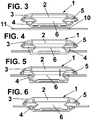
- Fig. 3 the sealing element is placed outside a hole 10 in a metal sheet 11.
- a force shown by arrow A in Fig. 1 .
- the second or lower lips 4 contact with the edge of the hole 10 and these second lips 4 folds upwardly (according to the position shown in the drawings) towards the tubular section 2, as shown in Fig. 4 .
Landscapes
- Engineering & Computer Science (AREA)
- General Engineering & Computer Science (AREA)
- Mechanical Engineering (AREA)
- Chemical & Material Sciences (AREA)
- Combustion & Propulsion (AREA)
- Transportation (AREA)
- Gasket Seals (AREA)
Abstract
Description
- The present invention refers to a sealing element for holes, e.g. for its application to metal sheets of vehicle bodyworks.
- Various ways of sealing holes made in vehicle bodywork panels or in other components are known, and in this regard, document
ES2006404A6 - This document discloses a plastic closure cap for closing an opening of a vehicle body, being based on the fact that the cover includes a sealing lip in an inclined arrangement and an elastic locking ring opposite to said lip, so that the latter rests on the periphery of the element or sheet on which the hole is made, in which the cover is precisely housed, while the locking ring rests on the lower face of said sheet or element.
- In this document it is also disclosed that, underneath the locking ring, a support is provided that can be configured by another elastic lip, which presses against the locking ring to keep it in permanent contact on the surface corresponding to the element or sheet in which the hole that closes the lid is made, to achieve a tightness.
- Although this type of closures is simple, it is evident that the sealing is sometimes not appropriate or optimal, due to the deformation or even possible breakage of both the support element and the interlock ring.
- To improve the sealing, document
EP1375308 A1 discloses another elastic closure cap in which a heat-deformable seal and anchoring lugs of the lid are included. - This document also discloses a seal for sealing holes in sheets, designed, in particular, to seal holes made in sheets, such as those of automobile bodyworks, comprising a cup-shaped body with a divergent peripheral outer wing, derived from a neck, formed by a bowl-shaped form of the body and diverging outward from said neck, and a diverging peripheral inner wing at the end of said neck opposite said outer wing.
- Documents
EP 0631923 A1 andEP 0779203 A1 disclose two sealing-sealants provided with two sealing zones or bands based on a flux material or glue, so that in the application of the sealant on the hole of the sheet a first sealing area is produced, in correspondence with the support of the perimetral and external lip of the body of the obturator on the upper surface of the sheet, with the interposition of the glue or flux and sealing material. - These known sealing elements comprise a body with a tubular section provided with a thick and straight wall, that requires a high insertion force due to the stiffness provided by said tubular section, said high insertion force being uncomfortable for the user.
- Therefore, one purpose of the present invention is to provide a sealing element that reduces its stiffness, keeping the sealing element tight.
- With the sealing element according to the present invention it is possible to solve said drawbacks, providing other advantages that are described below.
- The sealing element for holes according to the present invention comprises a body defining a tubular section, said body comprising a first lip and at least one second lip, wherein said tubular section comprises at least one pleat.
- With this at least one pleat in the tubular section, this tubular section is used as a bellows, providing a sealing element with a reduced stiffness, making flexible the tubular section and keeping the sealing element tight.
- Advantageously, said at least one pleat extends inwardly with respect to said tubular section.
- According to a preferred embodiment, the tubular section comprises only one pleat.
- Furthermore, said pleat defines an acute angle, even though it could define a curved portion and not an acute angle.
- Advantageously, the tubular section is made from a flexible material.
- Furthermore, according to a preferred embodiment, said first lip comprises an edge, wherein said edge is made from a different material than the rest of first lip.
- According to this preferred embodiment, the body, including the tubular section, the first lip and the second lip(s) are made from one piece.
- For a better understanding the above explanation and for the sole purpose of providing an example, some non-limiting drawings are included that schematically depict a practical embodiment.
-
Figs. 1-2 are perspective views of the sealing element according to the present invention; and -
Figs. 3-5 are sectional elevation views of the sealing element according to the present invention, during its insertion in a hole, from an initial position outside the hole to a final position inserted inside the hole. - As shown in the drawings, the sealing element according to the present invention comprises a body, indicated generally by
numeral reference 1, defining atubular section 2, and comprising afirst lip 3 and at least onesecond lip 4, in particular, a plurality ofsecond lips 4 according to the shown embodiment. - According to the position shown in the drawings, the
first lip 3 is the upper lip and thesecond lips 4 are the lower, but the sealing element according to the present invention can be used in any suitable position. - According to the shown embodiment, the
first lip 3 is curved towards the tubular section, and thesecond lips 4 extend upwardly in the position shown in the drawings. - Furthermore, the
first lip 3 comprise anedge 5, that is placed in the internal portion of this curvedfirst lip 3. - Preferably, the
whole body 1, including the first andsecond lips edge 5 is made from another material. - According to the present invention, the
tubular section 2 of thebody 1 is a bellows comprising at least onepleat 6. Even though the shown embodiment comprises just onepleat 6, thetubular section 2 can comprise a plurality of pleats. - It must be pointed out that in the present description and in the claims, the term "pleat" must be interpreted as any deformation that permits to increase and reduce the height of the
tubular section 2, such as a corrugation, undulation, fold, or the like. - The sealing element according to the present invention is used for sealing holes, e.g. holes made in metal sheets, such as made in a vehicle framework.
- These sealing elements need to be inserted easily and to provide a reliable sealing for said holes.
- In
Fig. 3 the sealing element is placed outside ahole 10 in a metal sheet 11. For placing the sealing element inside saidhole 10, first a force (shown by arrow A inFig. 1 ) is applied. - Firstly, the second or
lower lips 4 contact with the edge of thehole 10 and thesesecond lips 4 folds upwardly (according to the position shown in the drawings) towards thetubular section 2, as shown inFig. 4 . - When the
second lips 4 fold upwardly, the insertion of the lower portion of thetubular section 2 is permitted (Fig. 5 ), and thanks to thepleat 6 thistubular section 2 is extended with respect to the previous position, so that a reduced force is applied, in comparison with the force required by the conventional sealing elements. - When the
tubular section 2 is extended downwardly, there is a moment, that thesecond lips 4 completely pass through thehole 10, so that no contact is made between thesecond lips 4 and the edge of thehole 10. - In this position, the
second lips 4 fold downwardly thanks to the flexible nature of thesecond lip 4. - Finally, and thanks to its flexible nature of the
tubular section 2 and the presence of thepleat 6, the height of thetubular section 2 is contracted, as shown inFig. 6 , so that thesecond lips 4 contact with the lower side of the metal sheet 11. - In this position, the sealing of the
hole 10 is guaranteed by the first andsecond lips - Even though reference has been made to a specific embodiment of the invention, it is obvious for a person skilled in the art that the sealing element described herein is susceptible to numerous variations and modifications, and that all of the details mentioned can be substituted for other technically equivalent ones without departing from the scope of protection defined by the attached claims.
Claims (9)
- Sealing element for holes, comprising a body (1) defining a tubular section (2), said body (1) comprising a first lip (3) and at least one second lip (4), characterized in that said tubular section (2) comprises at least one pleat (6).
- Sealing element according to claim 1, wherein said at least one pleat (6) extends inwardly with respect to said tubular section (2).
- Sealing element according to claim 1 or 2, wherein the tubular section (2) comprises only one pleat (6).
- Sealing element according to anyone of the previous claims, wherein said pleat (6) defines an acute angle.
- Sealing element according to anyone of the previous claims, wherein the tubular section (2) is made from a flexible material.
- Sealing element according to anyone of the previous claims, wherein said tubular section (2) with said at least one pleat (6) defines a bellows.
- Sealing element according to claim 1, wherein said first lip (3) comprises an edge (5).
- Sealing element according to claim 7, wherein said edge (5) is made from a different material than the rest of first lip (3).
- Sealing element according to claim 1, wherein the body (1), including the tubular section (2), the first lip (3) and the at least one second lip (4) are made from one piece.
Priority Applications (1)
| Application Number | Priority Date | Filing Date | Title |
|---|---|---|---|
| EP19382506.4A EP3753819A1 (en) | 2019-06-18 | 2019-06-18 | Sealing element for holes |
Applications Claiming Priority (1)
| Application Number | Priority Date | Filing Date | Title |
|---|---|---|---|
| EP19382506.4A EP3753819A1 (en) | 2019-06-18 | 2019-06-18 | Sealing element for holes |
Publications (1)
| Publication Number | Publication Date |
|---|---|
| EP3753819A1 true EP3753819A1 (en) | 2020-12-23 |
Family
ID=67145755
Family Applications (1)
| Application Number | Title | Priority Date | Filing Date |
|---|---|---|---|
| EP19382506.4A Withdrawn EP3753819A1 (en) | 2019-06-18 | 2019-06-18 | Sealing element for holes |
Country Status (1)
| Country | Link |
|---|---|
| EP (1) | EP3753819A1 (en) |
Citations (10)
| Publication number | Priority date | Publication date | Assignee | Title |
|---|---|---|---|---|
| US3717324A (en) * | 1971-05-14 | 1973-02-20 | Volkswagenwerk Ag | Closure valve |
| ES2006404A6 (en) | 1987-04-22 | 1989-04-16 | United Carr Gmbh Trw | Closure cover of plastic |
| EP0631923A1 (en) | 1993-06-30 | 1995-01-04 | TRW United-Carr GmbH & Co. KG | Closure cap |
| EP0779203A1 (en) | 1995-12-11 | 1997-06-18 | TRW United-Carr GmbH & Co. KG | Closure cap consisting of two plastic parts |
| US5659924A (en) * | 1994-01-28 | 1997-08-26 | Chemcast Corporation | Grommet with flexible sealing passage |
| EP1375308A1 (en) | 2002-06-19 | 2004-01-02 | I.T.W. Espana, S.A. | Plug for sealing orifices |
| US20090230631A1 (en) * | 2005-06-03 | 2009-09-17 | Bsh Bosch Und Siemens Hausgeraete Gmbh | Sealing gasket for cooker under-button |
| DE102009057750A1 (en) * | 2009-06-24 | 2010-12-30 | Illinois Tools Work Inc., Glenview | Device for insertion into a component opening of an automobile |
| WO2011133374A1 (en) * | 2010-04-20 | 2011-10-27 | Illinois Tool Works Inc. | Hole plug assembly |
| EP2873894A1 (en) * | 2013-11-15 | 2015-05-20 | TRW Automotive Electronics & Components GmbH | Stopper |
-
2019
- 2019-06-18 EP EP19382506.4A patent/EP3753819A1/en not_active Withdrawn
Patent Citations (10)
| Publication number | Priority date | Publication date | Assignee | Title |
|---|---|---|---|---|
| US3717324A (en) * | 1971-05-14 | 1973-02-20 | Volkswagenwerk Ag | Closure valve |
| ES2006404A6 (en) | 1987-04-22 | 1989-04-16 | United Carr Gmbh Trw | Closure cover of plastic |
| EP0631923A1 (en) | 1993-06-30 | 1995-01-04 | TRW United-Carr GmbH & Co. KG | Closure cap |
| US5659924A (en) * | 1994-01-28 | 1997-08-26 | Chemcast Corporation | Grommet with flexible sealing passage |
| EP0779203A1 (en) | 1995-12-11 | 1997-06-18 | TRW United-Carr GmbH & Co. KG | Closure cap consisting of two plastic parts |
| EP1375308A1 (en) | 2002-06-19 | 2004-01-02 | I.T.W. Espana, S.A. | Plug for sealing orifices |
| US20090230631A1 (en) * | 2005-06-03 | 2009-09-17 | Bsh Bosch Und Siemens Hausgeraete Gmbh | Sealing gasket for cooker under-button |
| DE102009057750A1 (en) * | 2009-06-24 | 2010-12-30 | Illinois Tools Work Inc., Glenview | Device for insertion into a component opening of an automobile |
| WO2011133374A1 (en) * | 2010-04-20 | 2011-10-27 | Illinois Tool Works Inc. | Hole plug assembly |
| EP2873894A1 (en) * | 2013-11-15 | 2015-05-20 | TRW Automotive Electronics & Components GmbH | Stopper |
Similar Documents
| Publication | Publication Date | Title |
|---|---|---|
| US5297688A (en) | Closure for sealing a container rim | |
| US8727175B2 (en) | Wide-neck drum of thermoplastic material | |
| RU2010132842A (en) | CONTAINER AND LID KIT | |
| US4938378A (en) | Closure cover | |
| US9586735B2 (en) | Cover for opening and closing cans | |
| US8701921B2 (en) | Locking arrangement for a container closure | |
| BR9713016A (en) | Closing cover | |
| RU2019120189A (en) | CLOSURE FOR CONTAINER AND CONTAINER WITH SUCH CLOSURE | |
| MX2009006188A (en) | Packaging comprising a container associated with a lid equipped with reversible and reusable locking means. | |
| MX2023011089A (en) | Lid element and closure assembly for a beverage container. | |
| ES401312A1 (en) | Composite cap with pull-out panel | |
| IL120850A0 (en) | Method for manufacturing an easily-opened can lid and an easily-opened can lid | |
| US949974A (en) | Closure for cans. | |
| AU2013210995B2 (en) | Cover unit with adapter, cover, and sealing film for a container | |
| US4244480A (en) | Cap for sealing containers | |
| WO2020101932A1 (en) | Sealing element for orifices | |
| ES2450928T3 (en) | Method for tightly closing a container with a closure without a block | |
| US3344945A (en) | Resealable can | |
| JPH01161447U (en) | ||
| JP2008519737A5 (en) | ||
| BRPI0708964A2 (en) | container with a combination of lid ring closure in the manner of an inward compression lid and recloser lid | |
| ES2244662T3 (en) | SEALING DEVICE FOR DRINK CONTAINERS. | |
| JP2013535381A (en) | Glass bottle lid | |
| US20060102631A1 (en) | Closure cover | |
| US20090065467A1 (en) | Overcap for a container |
Legal Events
| Date | Code | Title | Description |
|---|---|---|---|
| PUAI | Public reference made under article 153(3) epc to a published international application that has entered the european phase |
Free format text: ORIGINAL CODE: 0009012 |
|
| STAA | Information on the status of an ep patent application or granted ep patent |
Free format text: STATUS: THE APPLICATION HAS BEEN PUBLISHED |
|
| AK | Designated contracting states |
Kind code of ref document: A1 Designated state(s): AL AT BE BG CH CY CZ DE DK EE ES FI FR GB GR HR HU IE IS IT LI LT LU LV MC MK MT NL NO PL PT RO RS SE SI SK SM TR |
|
| AX | Request for extension of the european patent |
Extension state: BA ME |
|
| STAA | Information on the status of an ep patent application or granted ep patent |
Free format text: STATUS: REQUEST FOR EXAMINATION WAS MADE |
|
| 17P | Request for examination filed |
Effective date: 20210517 |
|
| RBV | Designated contracting states (corrected) |
Designated state(s): AL AT BE BG CH CY CZ DE DK EE ES FI FR GB GR HR HU IE IS IT LI LT LU LV MC MK MT NL NO PL PT RO RS SE SI SK SM TR |
|
| STAA | Information on the status of an ep patent application or granted ep patent |
Free format text: STATUS: EXAMINATION IS IN PROGRESS |
|
| 17Q | First examination report despatched |
Effective date: 20230208 |
|
| STAA | Information on the status of an ep patent application or granted ep patent |
Free format text: STATUS: THE APPLICATION IS DEEMED TO BE WITHDRAWN |
|
| 18D | Application deemed to be withdrawn |
Effective date: 20250103 |