EP3753812A1 - Vehicle side body structure - Google Patents
Vehicle side body structure Download PDFInfo
- Publication number
- EP3753812A1 EP3753812A1 EP20162592.8A EP20162592A EP3753812A1 EP 3753812 A1 EP3753812 A1 EP 3753812A1 EP 20162592 A EP20162592 A EP 20162592A EP 3753812 A1 EP3753812 A1 EP 3753812A1
- Authority
- EP
- European Patent Office
- Prior art keywords
- side sill
- vehicle
- reinforcing member
- sill
- longitudinal direction
- Prior art date
- Legal status (The legal status is an assumption and is not a legal conclusion. Google has not performed a legal analysis and makes no representation as to the accuracy of the status listed.)
- Withdrawn
Links
- 230000003014 reinforcing effect Effects 0.000 claims abstract description 134
- 238000005452 bending Methods 0.000 claims abstract description 20
- 239000011324 bead Substances 0.000 claims description 6
- 230000002787 reinforcement Effects 0.000 description 10
- 238000003466 welding Methods 0.000 description 8
- 238000005192 partition Methods 0.000 description 7
- 239000013585 weight reducing agent Substances 0.000 description 3
- 230000007797 corrosion Effects 0.000 description 2
- 238000005260 corrosion Methods 0.000 description 2
- 239000003112 inhibitor Substances 0.000 description 2
- 230000037396 body weight Effects 0.000 description 1
- 230000000694 effects Effects 0.000 description 1
- 238000004070 electrodeposition Methods 0.000 description 1
- 239000000446 fuel Substances 0.000 description 1
- 239000007788 liquid Substances 0.000 description 1
- 230000002093 peripheral effect Effects 0.000 description 1
- 239000007921 spray Substances 0.000 description 1
- 238000005507 spraying Methods 0.000 description 1
Images


Classifications
-
- B—PERFORMING OPERATIONS; TRANSPORTING
- B62—LAND VEHICLES FOR TRAVELLING OTHERWISE THAN ON RAILS
- B62D—MOTOR VEHICLES; TRAILERS
- B62D21/00—Understructures, i.e. chassis frame on which a vehicle body may be mounted
- B62D21/15—Understructures, i.e. chassis frame on which a vehicle body may be mounted having impact absorbing means, e.g. a frame designed to permanently or temporarily change shape or dimension upon impact with another body
- B62D21/157—Understructures, i.e. chassis frame on which a vehicle body may be mounted having impact absorbing means, e.g. a frame designed to permanently or temporarily change shape or dimension upon impact with another body for side impacts
-
- B—PERFORMING OPERATIONS; TRANSPORTING
- B62—LAND VEHICLES FOR TRAVELLING OTHERWISE THAN ON RAILS
- B62D—MOTOR VEHICLES; TRAILERS
- B62D25/00—Superstructure or monocoque structure sub-units; Parts or details thereof not otherwise provided for
- B62D25/04—Door pillars ; windshield pillars
-
- B—PERFORMING OPERATIONS; TRANSPORTING
- B60—VEHICLES IN GENERAL
- B60J—WINDOWS, WINDSCREENS, NON-FIXED ROOFS, DOORS, OR SIMILAR DEVICES FOR VEHICLES; REMOVABLE EXTERNAL PROTECTIVE COVERINGS SPECIALLY ADAPTED FOR VEHICLES
- B60J5/00—Doors
- B60J5/04—Doors arranged at the vehicle sides
- B60J5/042—Reinforcement elements
- B60J5/0422—Elongated type elements, e.g. beams, cables, belts or wires
- B60J5/0423—Elongated type elements, e.g. beams, cables, belts or wires characterised by position in the lower door structure
- B60J5/0427—Elongated type elements, e.g. beams, cables, belts or wires characterised by position in the lower door structure the elements being arranged along the lower edge of door
-
- B—PERFORMING OPERATIONS; TRANSPORTING
- B60—VEHICLES IN GENERAL
- B60J—WINDOWS, WINDSCREENS, NON-FIXED ROOFS, DOORS, OR SIMILAR DEVICES FOR VEHICLES; REMOVABLE EXTERNAL PROTECTIVE COVERINGS SPECIALLY ADAPTED FOR VEHICLES
- B60J5/00—Doors
- B60J5/04—Doors arranged at the vehicle sides
- B60J5/042—Reinforcement elements
- B60J5/0422—Elongated type elements, e.g. beams, cables, belts or wires
- B60J5/0423—Elongated type elements, e.g. beams, cables, belts or wires characterised by position in the lower door structure
- B60J5/0429—Elongated type elements, e.g. beams, cables, belts or wires characterised by position in the lower door structure the elements being arranged diagonally
-
- B—PERFORMING OPERATIONS; TRANSPORTING
- B60—VEHICLES IN GENERAL
- B60J—WINDOWS, WINDSCREENS, NON-FIXED ROOFS, DOORS, OR SIMILAR DEVICES FOR VEHICLES; REMOVABLE EXTERNAL PROTECTIVE COVERINGS SPECIALLY ADAPTED FOR VEHICLES
- B60J5/00—Doors
- B60J5/04—Doors arranged at the vehicle sides
- B60J5/042—Reinforcement elements
- B60J5/0455—Reinforcement elements integrated in door structure or other door elements, e.g. beam-like shapes stamped in inner door panel
-
- B—PERFORMING OPERATIONS; TRANSPORTING
- B60—VEHICLES IN GENERAL
- B60J—WINDOWS, WINDSCREENS, NON-FIXED ROOFS, DOORS, OR SIMILAR DEVICES FOR VEHICLES; REMOVABLE EXTERNAL PROTECTIVE COVERINGS SPECIALLY ADAPTED FOR VEHICLES
- B60J5/00—Doors
- B60J5/04—Doors arranged at the vehicle sides
- B60J5/042—Reinforcement elements
- B60J5/0456—Behaviour during impact
- B60J5/0458—Passive coupling of the reinforcement elements to the door or to the vehicle body
-
- B—PERFORMING OPERATIONS; TRANSPORTING
- B62—LAND VEHICLES FOR TRAVELLING OTHERWISE THAN ON RAILS
- B62D—MOTOR VEHICLES; TRAILERS
- B62D25/00—Superstructure or monocoque structure sub-units; Parts or details thereof not otherwise provided for
- B62D25/02—Side panels
-
- B—PERFORMING OPERATIONS; TRANSPORTING
- B62—LAND VEHICLES FOR TRAVELLING OTHERWISE THAN ON RAILS
- B62D—MOTOR VEHICLES; TRAILERS
- B62D25/00—Superstructure or monocoque structure sub-units; Parts or details thereof not otherwise provided for
- B62D25/02—Side panels
- B62D25/025—Side sills thereof
-
- B—PERFORMING OPERATIONS; TRANSPORTING
- B62—LAND VEHICLES FOR TRAVELLING OTHERWISE THAN ON RAILS
- B62D—MOTOR VEHICLES; TRAILERS
- B62D25/00—Superstructure or monocoque structure sub-units; Parts or details thereof not otherwise provided for
- B62D25/08—Front or rear portions
- B62D25/16—Mud-guards or wings; Wheel cover panels
-
- B—PERFORMING OPERATIONS; TRANSPORTING
- B62—LAND VEHICLES FOR TRAVELLING OTHERWISE THAN ON RAILS
- B62D—MOTOR VEHICLES; TRAILERS
- B62D27/00—Connections between superstructure or understructure sub-units
- B62D27/02—Connections between superstructure or understructure sub-units rigid
- B62D27/023—Assembly of structural joints
Definitions
- the present invention relates to a vehicle side body structure and to a vehicle comprising a vehicle side body structure.
- a side sill is subjected to a load directed to a vehicle width inner side (that is, a load causing such a bending deformation of a portion joining the side sill to the center pillar, wherein this portion is displaced from in a longitudinal direction to a vehicle width inner side in a vehicle plan view) in conjunction with the load applied from a center pillar to the vehicle width inner side (a cabin side).
- a load directed to a vehicle width inner side that is, a load causing such a bending deformation of a portion joining the side sill to the center pillar, wherein this portion is displaced from in a longitudinal direction to a vehicle width inner side in a vehicle plan view
- Patent document 1 In order to protect an occupant against such a lateral collision, a side sill that is reinforced against a load directed to the vehicle width inner side as described above is proposed in Patent document 1 below, for example.
- the side sill in Patent document 1 includes a side sill reinforcement (hereinafter referred to as a "side sill rein”), and, in the longitudinal direction of the side sill, the side sill rein includes a base member and an extending member that is coupled to a rear end portion of the base member.
- side sill rein a side sill reinforcement
- the extending member has a coupled portion that is fixed to the base member, and the coupled portion is coupled to the rear end portion of the base member from the vehicle width inner side by welding or the like.
- a coupled portion between the extending member and the base member is reinforced by an overlapping structure of the coupled portion of the extending member and the rear end portion of the base member.
- At least the coupled portion of the side sill adopts the above-described overlapping structure in order to improve the bending rigidity against the load to the vehicle width inner side.
- the overlapping structure is arranged over the entire coupled portion from an upper end to a lower end, that is, the entire coupled portion is along a cross-sectional shape that is perpendicular to the longitudinal direction, there is still room for a further weight reduction of the side sill.
- a lateral collision load is applied to the joined portion of the side sill to the center pillar, via the center pillar. Accordingly, from a perspective of the weight reduction, it is considered that a local reinforcement of this joined portion to the center pillar is effective. However, in such a case, a difference in the rigidity between a region, where the center pillar is located, and a peripheral portion thereof on each of front and rear sides in the longitudinal direction of the side sill, might occur. In addition, reinforcement of the entire side sill in the longitudinal direction would result in a weight increase of the side sill.
- the inventors of the present application focused their attention to the design of the side sill in consideration of vehicle body members that are provided around the side sill, other than the center pillar.
- the present invention has been made in view of such a problem and therefore has a purpose of providing a vehicle side body structure capable of improving the bending rigidity against an inward load in a vehicle width direction during a lateral collision while preventing or at least reducing a weight increase of a side sill.
- a vehicle side body structure includes: a side sill having a substantially closed cross-sectional structure extending in a vehicle longitudinal direction; a wheel house comprising a front lower portion raised from a rear portion of the side sill; a center pillar having a substantially closed cross-sectional structure extending in a substantially upward direction from an intermediate portion of the side sill; and a door arranged to open/close an opening formed to be opened at a position above the side sill and behind the center pillar.
- the door comprises an impact bar arranged such that a rear portion thereof overlaps the rear portion of the side sill in a vehicle side view when the door is closed.
- the side sill includes a side sill reinforcing member configured to reinforce a bending rigidity against a load to an inner side in a vehicle width direction.
- the side sill reinforcing member is at least provided in the intermediate portion of the side sill, in which the center pillar is located, and in the rear portion of the side sill in a longitudinal direction of the side sill.
- the side sill reinforcing member is at least provided in the intermediate portion of the side sill and the rear portion of the side sill in the longitudinal direction of the side sill.
- An aspect of the present invention further includes a wheel house reinforcing member that extends in an upward direction from the rear portion of the side sill and along the wheel house. Additionally, the wheel house reinforcing member may be arranged to overlap the side sill reinforcing member in or near a region where a rear portion of the impact bar is located in the vehicle side view. In other words, when the door is closed, the wheel house reinforcing member is arranged to overlap the side sill reinforcing member in or near a region where a rear portion of the impact bar is located in the vehicle side view.
- the wheel house reinforcing member is joined (e.g., welded) to the side sill reinforcing member. Additionally, when the door is a closed configuration, the rear portion of the impact bar may overlap a joined portion between the wheel house reinforcing member and the side sill reinforcing member in the vehicle side view.
- the side sill reinforcing member and the wheel house reinforcing member may have a ridgeline extending substantially in the vehicle longitudinal direction and a ridgeline extending substantially in a vertical direction, respectively.
- the ridgeline extending substantially in the vehicle longitudinal direction and the ridgeline extending substantially in the vertical direction are defined to continue in the vehicle side view. In other words, the ridgeline may extend continuously.
- the side sill reinforcing member has the ridgeline extending substantially in the vehicle longitudinal direction, it is possible to further improve the bending rigidity against the load to the inner side in the vehicle width direction of the side sill in a vehicle plan view.
- the wheel house reinforcing member has the ridgeline extending substantially in the vertical direction, it is possible to further improve the bending rigidity in the vehicle side view against the load to the inner side in the vehicle width direction of the side sill and torsion rigidity around an axis extending in the longitudinal direction of the side sill.
- these ridgelines may be defined to continue in the vehicle side view, it is possible to further improve the bending rigidity of the side sill against the load to the inner side in the vehicle width direction during the lateral collision.
- the impact bar may be arranged to overlap the center pillar in the vehicle side view.
- the side sill reinforcing member may comprise an upper reinforcing member located in an upper portion of the side sill and a lower reinforcing member located in a lower portion of the side sill.
- an outer wall bead may be provided in an outer wall and located in an intermediate portion between the upper reinforcing member and the lower reinforcing member in the vertical direction.
- the upper reinforcing member and the lower reinforcing member may extend continuously in a vehicle longitudinal direction, from a position in front of the center pillar to the rear portion of the side sill so as to cross the center pillar along the longitudinal direction of the side sill.
- a further aspect of the present invention relates to a vehicle comprising the vehicle side body structure above disclosed.
- the vehicle side body structure may be mounted on a lateral side and/or both sides of the vehicle.
- the present invention it is possible to improve the bending rigidity against the inward load in the vehicle width direction during the lateral collision while preventing or at least reducing a weight increase of the side sill.
- an arrow F, an arrow U, and an arrow OUT respectively indicate a vehicle front direction, a vehicle up direction, and an outer side in a vehicle width direction (a vehicle right direction).
- the outer side in the vehicle width direction (a cabin outer side)
- an inward direction in the vehicle width direction (a cabin inner side)
- a vehicle width inner side a vehicle side body structure, which will be described below, is provided substantially and bilaterally symmetrical on left and right sides of a vehicle.
- side openings 2f, 2r are formed in a vehicle side body section.
- a roof side rail 3 that extends substantially in a longitudinal direction is provided along upper sides of the side openings 2f, 2r.
- a side sill 4 that extends substantially in the longitudinal direction is provided along lower sides of the side openings 2f, 2r.
- the openings 2f, 2r are formed in a space defined by the side sill 4 and the center pillar 5.
- a center pillar 5 that extends in a vertical direction (direction U in the Figures), i.e, an upward direction, is provided at an intermediate position between the side openings 2f, 2r in a vehicle longitudinal direction.
- an upper end is joined to an intermediate portion of the roof side rail 3, which extends in the vehicle longitudinal direction
- a lower end of the center pillar 5 is joined to an intermediate portion of the side sill 4, which extends in the vehicle longitudinal direction.
- the side openings 2f, 2r are partitioned into openings on vehicle front and rear sides by the center pillar 5 and are provided as getting-on/off openings 2f, 2r (the front getting-on/off opening 2f and the rear getting-on/off opening 2r).
- the vehicle side body portion includes a side door (6) that opens/closes respective one of the front and rear getting-on/off openings 2f, 2r.
- the side door 6 is arranged to open/close the openings 2r and/or 2f that are formed by the arrangement of the side sill 4 and the center pillar 5 (see Figs. 1 and 2 ).
- the side door on a front side (a front side door) is not illustrated while the side door 6 on a rear side (a rear side door 6) is partially illustrated.
- a vehicle user may access to the vehicle through the opening 2r/2f, while when the door 6 is closed, following a rotational movement about a hinge axis, the space defined by the opening 2r/2f is occupied by the door 6 thus the user cannot access to the vehicle.
- the rear side door 6 includes: a door body 61 constructed of a door outer panel, a door inner panel, and the like; and a plurality of impact bars 63 extending in the vehicle longitudinal direction, when the door is mounted on the vehicle.
- a front end of the rear side door 6 is supported by a portion on each of upper and lower sides of the center pillar 5 via an unillustrated hinge bracket.
- the door body 61 is provided with an impact bar reinforcement 64 that extends along a rear side, a front side, and a lower side thereof.
- the impact bars 63 are provided at different heights from each other and are disposed between a front side and a rear side of the impact bar reinforcement 64 so as to couple the front side and the rear side.
- Fig. 2 only illustrates an impact bar 63 that is located at a lowest position of the plurality of impact bars 63. A description will hereinafter be made on the impact bar 63 that is located at the lowest position of the plurality of impact bars.
- the impact bar 63 is formed to have a substantially M-shaped cross section in a direction substantially perpendicular to a longitudinal direction (see in particular Fig. 5 ).
- the impact bar 63 is formed with a front flange 63f and a rear flange 63r, each of which is formed to be wider than an intermediate portion in the longitudinal direction, at front and rear ends.
- the front flange 63f is fixed to a lower portion of the front side of the impact bar reinforcement 64
- the rear flange 63r is fixed to a corner portion 64c between a lower portion of the rear side and a lower side of the impact bar reinforcement 64.
- the impact bar 63 is provided in a lower portion of the rear side door 6 in a manner to be tilted upward to the front and downward to the rear.
- a joint position of the rear flange 63r of the impact bar 63 to the rear side of the impact bar reinforcement 64 is located at a lower end of the lower portion of the rear side as described above, that is, the corner portion 64c between the rear side and the lower side.
- the front flange 63f of the impact bar 63 overlaps the center pillar 5 in a vehicle side view
- the rear flange 63r of the impact bar 63 that is, the joint portion to the corner portion 64c between the rear side and the lower side of the impact bar reinforcement 64
- a vehicle side view refers to a view along a direction being opposite to the direction OUT illustrated in Figs. 1 and 2 .
- the side sill 4 is a vehicle body rigid member that has a closed cross-sectional space 4s.
- the side sill 4 is a vehicle body rigid member that, when assembled to a vehicle, is mounted on at least one lateral side of a vehicle.
- the side sill 4 extends in the vehicle longitudinal direction, when the vehicle side body structure comprising the side sill 4 is mounted on a lateral side of a vehicle.
- the longitudinal direction of the side sill 4 substantially corresponds to vehicle longitudinal direction.
- the side sill 4 may comprise a first member 41, a second member 42, and a third member 43 constituting the closed cross-sectional space 4s; and an exterior panel 44 (only illustrated in Fig. 12 ) attached to the vehicle width outermost side of the side sill 4.
- the first member 41 is provided on the vehicle width inner side of the side sill 4.
- the side sill inner 4i of the first member 41 substantially protrudes to the vehicle width inner side along a direction substantially opposite to the "OUT" direction. More specifically, with reference to Fig.
- the first member 41 may be integrally formed by including an upper end flange 41a extending in the vertical direction, an upper wall 41b extending to the vehicle width inner side from a lower end of the upper end flange 41a, an inner wall 41c extending downward from a vehicle width inner end of the upper wall 41b, a lower wall 41d extending to the vehicle width outer side from a lower end of the inner wall 41c, and a lower end flange 41e extending downward from a vehicle width outer end of the lower wall 41d.
- the second member 42 and the third member 43 are provided on the vehicle width outer side of the first member 41.
- the second member 42 may be integrally formed by including an upper end flange 42a located in an upper portion of the side sill outer 4o and an intermediate portion in the vertical direction and extending in the vertical direction, an upper wall 42b extending to the vehicle width outer side from a lower end of the upper end flange 42a, an outer wall 42c extending downward from an vehicle width outer end of the upper wall 42b, and a lower end flange 42d extending to the vehicle width inner side from a lower end of the outer wall 42c.
- the third member 43 is located in a lower portion of the side sill outer 4o and may be integrally formed by including a lower wall 43a extending to the vehicle width inner side and a lower end flange 43b extending downward from a vehicle width inner end of the lower wall 43a.
- the upper end flanges 41a, 42a of the first member 41 and the second member 42 as well as the lower end flanges 41e, 43b of the first member 41 and the third member 43 may be integrally joined to each other by spot welding or the like. Furthermore, the lower end flange 42d of the second member 42 may be joined to the lower wall 43a of the third member 43 from above (a side of the closed cross-sectional space 4s).
- the side sill 4 constitutes the closed cross-sectional space 4s therein by the upper wall 41b, the inner wall 41c, and the lower wall 41d of the first member 41, the upper wall 42b and the outer wall 42c of the second member 42, and the lower wall 43a of the third member 43.
- ridgelines 45a, 45b, 45c, 45d extending substantially in the vehicle longitudinal direction are respectively defined between the upper wall 42b and the outer wall 42c, the outer wall 42c and the lower end flange 42d, the upper wall 41b and the inner wall 41c, and the inner wall 41c and the lower wall 41d.
- the ridgeline 45a defined between the upper wall 42b and the outer wall 42c that is, the ridgeline 45a defined at an upper end of the outer wall 42c is set as an upper outer ridgeline 45a
- the ridgeline 45b defined between the outer wall 42c and the lower end flange 42d that is, the ridgeline 45b defined at the lower end of the outer wall 42c is set as a lower outer ridgeline 45b.
- the outer wall 42c of the side sill 4 is provided with an outer wall bead 42cc, which is dented to the side of the closed cross-sectional space 4s, near a center in the vertical direction.
- the third member 43 is further formed with a vehicle width outer end flange 43c extending to the vehicle width outer side from a vehicle width outer end of the lower wall 43a.
- the vehicle width outer end flange 43c extends to the vehicle width outer side from an upper end portion of an overlapping portion 46 between the lower end flange 42d of the second member 42 and the lower wall 43a of the third member 43.
- the vehicle width outer end flange 43c is projected downward and to the vehicle width outer side from a position between the outer wall 42c and the lower wall 43a of the side sill 4 in a manner to be bent from these outer wall 42c and lower wall 43a.
- a ridgeline 43cc extending substantially in the vehicle longitudinal direction is defined in a base end portion of the vehicle width outer end flange 43c.
- this ridgeline 43cc may match or may be located near the above-described lower outer ridgeline 45b.
- the ridgeline 43cc located in the base end portion of the vehicle width outer end flange 43c is located below and near the lower outer ridgeline 45b.
- the lower wall 43a of the third member 43 in the side sill 4 may comprise a plurality of through holes 47, each of which has a substantially circular shape in a plan view, along the vehicle longitudinal direction.
- a longitudinal direction of the side sill 4 substantially corresponds to the vehicle longitudinal direction.
- Each of these through holes 47 may be used to insert a corrosion inhibitor spray gun (not illustrated) in the closed cross-sectional space 4s in order to introduce an electrodeposition liquid or the like into the closed cross-sectional space 4s of the side sill 4 or spraying a corrosion inhibitor on an inner surface that is a surface facing the closed cross-sectional space 4s of the side sill 4.
- a floor panel 100 that forms an unillustrated tunnel portion raised upward in a central portion in the vehicle width direction and extending in the vehicle longitudinal direction is stretched between the above-described side sills 4 on both sides in a vehicle body lower portion, when both side sills 4 are mounted on both sides of the vehicle.
- a kick-up portion 101 is provided in a manner to be raised upward from the rear end portion.
- a front crossmember 110 (2.0 crossmember) and an intermediate crossmember 120 (2.5 crossmember), each of which extends in the vehicle width direction and couples the side sill 4 and the tunnel section, are disposed on an upper surface of the floor panel 100 on both sides of the tunnel section.
- each of the front crossmember 110 and the intermediate crossmember 120 is formed in a hat shape that is opened downward and, with the floor panel 100, constitutes a closed cross-sectional space extending in the vehicle width direction.
- a rear crossmember 130 (3.0 crossmember) that is joined and fixed to the upper portion from a back surface side and has a closed cross-sectional space extending in the vehicle width direction is disposed.
- crossmembers 110, 120, 130 are disposed away from each other in the vehicle longitudinal direction.
- the front crossmember 110 is disposed to be located in an intermediate portion of the front getting-on/off opening 2f
- the intermediate crossmember 120 is disposed to be located on the center pillar 5
- the rear crossmember 130 is disposed to be located in an intermediate portion of the rear getting-on/off opening 2r.
- flanges 110a, 120a, 130a formed at outer ends in the vehicle width direction of these crossmembers 110, 120, 130 are joined to the inner wall 41c of the side sill 4, and each of these crossmembers 110, 120, 130 can receive a load to the vehicle width inner side transmitted from the side sill 4.
- a rear wheel house 90 that forms a lower portion of a rear side of the rear getting-on/off opening 2r from a rear portion of a lower side thereof is disposed behind the side sill 4.
- the rear wheel house 90 includes a rear wheel house inner 91 and a rear wheel house outer 92, each of which is formed in an arch shape and projected upward in a vehicle side view, and these accommodate a rear wheel from above.
- a front lower portion 92a of the rear wheel house outer 92 is joined to a rear end of the side sill 4.
- the front lower portion 92a of the rear wheel house outer 92 extends substantially from the rear portion of the side sill 4 in an upward direction.
- the upward direction may substantially correspond to the vehicle up direction U.
- the side sill 4 includes a plurality of sections (partition walls), namely sections 21F, 21R, 22F, 22R, each of which partitions the closed cross-sectional space 4s in the vehicle longitudinal direction.
- the plural sections 21F, 21R, 22F, 22R are provided along the vehicle longitudinal direction of the side sill 4.
- the plural sections 21F, 21R, 22F, 22R are at least provided at four positions in a front portion and a rear portion of a center pillar arrangement region 4Ra and a portion in front of and a portion behind the center pillar arrangement region 4Ra in the longitudinal direction of the side sill 4.
- center pillar arrangement region 4Ra is located in the intermediate portion of the side sill 4 in the vehicle longitudinal direction.
- sections 21F, 21R, 22F, 22R are set as a pillar forward section 21F, a pillar front section 22F, a pillar rear section 22R, and a pillar rearward section 21R in an order from a front side to a rear side.
- each of the pillar front section 22F and the pillar rear section 22R includes a vertical wall 22a that partitions the closed cross-sectional space 4s in the vehicle longitudinal direction.
- each of the pillar forward section 21F and the pillar rearward section 21R is constructed of an outer section component 23 located on the vehicle width outer side and an inner section component 24 located on the vehicle width inner side.
- the outer section component 23 includes a front wall 23a and a rear wall 23b that are separately disposed along the vehicle longitudinal direction
- the inner section component 24 includes a vertical wall 24a extending in the vertical direction and the vehicle width direction.
- the above-described pillar front section 22F partitions the vehicle width outer side of the closed cross-sectional space 4s by the vertical wall 22a.
- the pillar forward section 21F partitions the vehicle width outer side of the closed cross-sectional space 4s by the front wall 23a and the rear wall 23b provided in the outer section component 23, and partitions the vehicle width inner side of the closed cross-sectional space 4s by the vertical wall 24a provided in the inner section component 24.
- the side sill outer 4o which is constructed of the second member 42 and the third member 43, is provided with first reinforcing members 30U, 30D and a second reinforcing member 31 configured to reinforce a bending rigidity against a load directed to the vehicle width inner side, e.g., in case of a lateral collision.
- the first reinforcing members 30U, 30D may comprise a first upper reinforcing member 30U located in an upper portion of the side sill 4 and a first lower reinforcing member 30D located in a lower portion of the side sill 4.
- an outer wall bead 42cc may be provided at an intermediate position in the vertical direction located between the first upper reinforcing member 30U and the first lower reinforcing member 30D.
- the first upper reinforcing member 30U may be joined to the side sill 4 at a height position of a center pillar joined portion 4A.
- the first upper reinforcing member 30U may be integrally formed substantially in an L-shape in the cross-sectional view that is perpendicular to the vehicle longitudinal direction by a lateral side 33 (see Fig. 11 and Fig. 12 ) extending in the vehicle width direction along the upper wall 42b of the second member 42 in the side sill 4 and a vertical side 34 extending downward from a vehicle width outer end of the lateral side 33.
- the first upper reinforcing member 30U is partially provided in the cross-sectional view that is perpendicular to the longitudinal direction of the side sill 4.
- the first upper reinforcing member 30U may be joined to the side sill 4 in a manner to only cover the single ridgeline (the ridgeline 45a in the present example) among the plural (four in the present example) ridgelines 45a, 45b, 45c, 45d extending substantially in the longitudinal direction of the side sill 4.
- the lateral side 33 and the vertical side 34 of the first upper reinforcing member 30U are respectively arranged on the upper wall 42b of the second member 42 and the outer wall 42c of the second member 42 from the side of the closed cross-sectional space 4s such that a ridgeline 35 provided between the lateral side 33 and the vertical side 34 abuts the upper outer ridgeline 45a provided in the corner portion, and the first upper reinforcing member 30U may be joined at a plurality of positions substantially along the vehicle longitudinal direction by welding or the like.
- the first lower reinforcing member 30D may be joined to the side sill 4 at a position lower than the height position of the center pillar joined portion 4A.
- the first lower reinforcing member 30D may be integrally formed substantially in an L-shape in the cross-sectional view that is perpendicular to the vehicle longitudinal direction by a lateral side 36 extending in the vehicle width direction along the lower wall 41d of the third member 43 in the side sill 4 and a vertical side 37 extending upward from a vehicle width outer end of the lateral side 36.
- the vertical side 37 and the lateral side 36 of the first lower reinforcing member 30D may be respectively joined to the outer wall 42c of the second member 42 and the lower wall 43a of the third member 43 via the lower end flange 42d of the second member 42 at plural positions from the side of the closed cross-sectional space 4s along substantially the vehicle longitudinal direction by welding or the like such that a ridgeline 38 between the vertical side 37 and the lateral side 36 abuts the lower outer ridgeline 45b provided in the corner portion.
- these first upper reinforcing member 30U and first lower reinforcing member 30D may extend continuously in the vehicle longitudinal direction from a position in front of the center pillar 5 to the rear portion of the side sill 4 in a manner to cross the center pillar 5 along the longitudinal direction of the side sill 4.
- the first upper reinforcing member 30U will be described in detail.
- a front end of the first upper reinforcing member 30U may extend to a position in front of the pillar forward section 21F as illustrated in Fig. 9 to Fig. 11 and may also extend to a position where the first upper reinforcing member 30U overlaps the front crossmember 110 in the vehicle side view as illustrated in Fig. 11 .
- a rear end of the first upper reinforcing member 30U may extend to a position behind the pillar rearward section 21R as illustrated in Fig. 9 and Fig. 11 , and may also extends to a position behind the rear crossmember 130 as illustrated in Fig. 11 .
- first upper reinforcing member 30U may be provided in a manner to cross the pillar forward section 21F, the pillar front section 22F, the pillar rear section 22R, and the pillar rearward section 21R, and is also provided in a manner to cross the crossmembers 110, 120, 130 on the front side, the intermediate side, and the rear side.
- the above-described second reinforcing member 31 may be provided in the rear portion of the side sill 4 and extends upward from the rear portion of the side sill 4 and along the rear wheel house 90.
- the second reinforcing member 31 includes an upward extending portion 31u extending upward and a forward extending section 31f extending forward.
- the upward extending section 31u and the forward extending section 31f are respectively joined to the front lower portion 92a of the rear wheel house outer 92 and the rear portion of the side sill 4 by welding or the like.
- the second reinforcing member 31 may be integrally formed in a substantially triangular shape in the vehicle side view. More particularly, the second reinforcing member 31 may comprise a side wall 31a extending in the vertical direction and the vehicle longitudinal direction, a vertical wall 31b extending to the vehicle width inner side from an upper edge of the side wall 31a, and a flange 31c extending upward from a vehicle width inner end of the vertical wall 31b.
- ridgelines 31d, 31e may continuously extend along an extending direction of the second reinforcing member 31 are respectively defined between the side wall 31a and the vertical wall 31b and between the vertical wall 31b and the flange 31c. These ridgelines 31d, 31e may extend substantially along the vertical direction in the upward extending portion 31u, and extend substantially along the vehicle longitudinal direction in the forward extending section 31f.
- the forward extending section 31f of the second reinforcing member 31 is joined to the rear portion and the upper portion of the side sill 4 from the vehicle width outer side. More specifically, as illustrated in Fig. 5 and Fig. 6 , in the second reinforcing member 31, the flange 31c of the forward extending section 31f and the side wall 31a of the forward extending section 31f are respectively joined to the upper end flange 42a of the second member 42 and the outer wall 42c of the second member 42 in the side sill 4 in a manner to cover the upper end flange 42a and the outer wall 42c from the vehicle width outer side, and the vertical wall 31b of the forward extending section 31f is joined to the upper wall 42b of the second member 42 in a manner to cover the upper wall 42b from above.
- a front portion of the second reinforcing member 31, that is, the forward extending section 31f is located on the vehicle width outer side of a rear portion of the first upper reinforcing member 30U and overlaps the rear portion of the first upper reinforcing member 30U in the vehicle side view (that is, in the vehicle width direction).
- the second reinforcing member 31 overlaps the rear end flange 63r of the impact bar 63 in the vehicle side view.
- the rear end flange 63r of the impact bar 63 which is provided in the lower portion of the rear side door 6, is configured to overlap the rear portion of the side sill 4 in the vehicle side view. Accordingly, as illustrated in Fig. 3, Figs. 4(a), (b) , and Fig.
- the rear end flange 63r of the impact bar 63, the forward extending section 31f of the second reinforcing member 31, the second member 42 of the side sill 4, and the rear portion of the first upper reinforcing member 30U are sequentially provided from the outer side to the inner side in the vehicle width direction, and these overlap each other in the vehicle side view.
- the second reinforcing member 31 and the first upper reinforcing member 30U are joined to each other at the joined positions wa, wb in a manner to hold the second member 42 of the side sill 4 therebetween.
- the rear end flange 63r of the impact bar 63 overlaps the joined portion (at least the joined position wa) between the second reinforcing member 31 and the first upper reinforcing member 30U in the vehicle side view.
- the ridgeline 35 defined between the lateral side 33 and the vertical side 34 of the first upper reinforcing member 30U extends substantially for an entire length of the first upper reinforcing member 30U in the vehicle longitudinal direction.
- the ridgelines 31d, 31e of the second reinforcing member 31 may extend substantially along the vertical direction in the upward extending portion 31u located in the rear portion of the second reinforcing member 31, and may extend substantially along the vehicle longitudinal direction in the forward extending section 31f positioned in the front portion of the second reinforcing member 31.
- the rear portion of the ridgeline 35 extending substantially in the longitudinal direction and the lower portions (front portions) of the ridgelines 31d, 31e extending substantially in the vertical direction may be formed to be continued in the vehicle side view (see Fig. 4(a) , Fig. 5 , Fig. 6 , and Fig. 12 ).
- the above-described center pillar 5 includes a pillar inner 51 and a pillar outer 52.
- the center pillar 5 is substantially vertically provided in the side sill 4 by welding lower portions of these to the side sill 4.
- the lower portion of the center pillar 5 (a root region for the side sill 4) is formed such that a width thereof is gradually increased downward in the vehicle longitudinal direction from a portion of the lower portion near an upper end 52a (see Fig. 1, Fig. 2 , and Fig. 9 ) to the upper end of the side sill 4.
- the pillar inner 51 may be formed in a vertical wall shape (a substantially flat plate shape) in which a substantially entire portion in the vertical direction extends in the vehicle width direction, and may be formed with a flange 51d on each of front and rear sides thereof.
- the pillar outer 52 may be integrally formed by including an outer wall 52b extending in the vertical direction and the vehicle width direction, front and rear vertical walls 52c extending to the vehicle width inner side from front and rear ends of the outer wall 52b, a flange 52d on each of the front and rear sides formed along the vertical wall 52c such that the substantially entire portion in the vertical direction has a hat-shaped cross-sectional shape opened to the vehicle width inner side in the cross-sectional view that is perpendicular to the vertical direction.
- the center pillar 5 is configured to have a closed cross-sectional space 5s extending in the vertical direction between the pillar inner 51 and the pillar outer 52 by joining the front edge flanges 51d, 52d and the rear edge flanges 51d, 52d of these.
- a lower portion of the pillar outer 52 is joined to the second member 42 of the side sill 4, and this joint structure will be described.
- the lower portion of the pillar outer 52 is formed with a lower end flange 52e extending downward from a lower end of the outer wall 52b, and this lower end flange 52e is joined to the outer wall 42c of the second member 42 in the side sill 4.
- the center pillar 5 and the side sill 4 are arranged such that the outer wall 52b and the outer wall 42c are substantially flush in the vehicle width direction, when the vehicle side body structure is mounted on a side of a vehicle.
- each of the front and rear flanges 52d of the pillar outer 52 and each of the front and rear flanges 51d of the pillar inner 51 are integrally joined to each other as described above.
- lower portions of the flanges 51d, 52d on each of the front and rear sides are integrally joined to each other in a manner to hold the upper end flange 42a of the second member 42 on a side of the side sill outer 4o from both of the inner and outer sides in the vehicle width direction.
- each of the front and rear flanges 51d, 52d of the center pillar 5 and the upper end flange 42a of the side sill 4 are arranged to be substantially flush in the vehicle width direction.
- the vertical wall 52c on each of the front and rear sides of the pillar outer 52 is brought into a state where a lower end thereof contacts the upper wall 42b of the second member 42 in the side sill 4, and the vertical wall 52c extending in the vertical direction on each of the front and rear sides and the upper wall 42b extending in the longitudinal direction in the second member 42 of the side sill 4 continuously and smoothly extend in a corner portion of these in the vehicle side view.
- the pillar inner 51 is formed such that the lower portion is widened in the vehicle longitudinal direction so as to correspond to the lower portion of the pillar outer 52, and forms an extending portion 55 that extends to be lower than an upper end position of the side sill 4.
- the extending portion 55 is disposed in the closed cross-sectional space 4s in a manner to partition the closed cross-sectional space 4s into spaces on the inner and outer sides in the vehicle width direction.
- an upper end 55u of the extending portion 55 is interposed between the upper end flanges 41a, 42a of the first member 41 and the second member 42 in the side sill 4 and is integrally joined to these upper end flanges 41a, 42a.
- a lower end 55d of the extending portion 55 is interposed between the lower end flanges 41e, 43b of the first member 41 and the third member 43 in the side sill 4 and is integrally joined to these lower end flanges 41e, 43b.
- the lower portion of the pillar inner 51 including the extending portion 55 is formed to be wide in the vehicle longitudinal direction.
- the pillar inner 51 has a pillar inner upper 56 and a pillar inner lower 57 provided below the pillar inner upper 56.
- an overlapping portion 58 between the lower portion of the pillar inner upper 56 and the upper portion of the pillar inner lower 57 is provided in the above-described extending portion 55, and the lower portion of the pillar inner upper 56 and the upper portion of the pillar inner lower 57 are joined to each other at plural positions along the vehicle longitudinal direction of the extending portion 55 by spot welding or the like (see " ⁇ " in Fig. 8 ).
- the pillar front section 22F and the pillar rear section 22R described above are provided on the vehicle width outer side of the extending portion 55, and the pillar front section 22F and the pillar rear section 22R are respectively provided on a front end side of the extending portion 55 and a rear end side of the extending portion 55 in a manner to be separated from each other in the vehicle longitudinal direction.
- the vehicle side body structure As illustrated in Fig. 1 and Fig. 2 , the vehicle side body structure according to the embodiment described above is the vehicle side body structure that includes: the side sill 4 that has the closed cross-sectional space 4s (see Fig. 10 ) (the closed cross-sectional structure).
- the side sill 4 When the vehicle side body structure is mounted on a side of a vehicle, the side sill 4 extends in the vehicle longitudinal direction.
- the wheel house 90 comprises a front lower portion 92a raised from the rear portion of the side sill 4. In other words, the front lower portion 92a extends from the rear portion of the side sill 4.
- the center pillar 5 has a closed cross-sectional space 5s (the closed cross-sectional structure) (see Fig.
- a rear side door 6 serves as the door for opening/closing the rear getting-on/off opening 2r that is the opening formed to be opened at the position above the side sill 4 and behind the center pillar 5. More particularly, the rear getting-on/off opening 2r is the opening formed between the side sill 4 and the center pillar 5.
- a position above the side sill 4 may be a position above the side sill 4 in a vehicle up direction (direction U), while a position behind the center pillar 5 may be a position behind the center pillar 5 along a direction being opposite to a vehicle front direction (direction F).
- the door 6 comprises an impact bar 63 that is disposed such that, when the rear side door 6 is closed the rear flange 63r (the rear portion) of the impact bar 63 provided to the rear side door 6 overlaps the rear portion of the side sill 4 in a vehicle side view (that is, in the vehicle width direction).
- the side sill 4 includes a first upper reinforcing member 30U as the side sill reinforcing member configured to reinforce the bending rigidity against a load that may be directed to the vehicle width inner side, when the vehicle side body structure is mounted on a side of a vehicle, for example in case of a lateral collision.
- the first upper reinforcing member 30U is provided at least in the intermediate portion (the center pillar arrangement region 4Ra) of the side sill 4, in which at least the center pillar 5 is located, and in the longitudinal direction of the side sill 4 as illustrated in Fig. 9 to Fig. 11 , and is provided in the rear portion of the side sill 4 as illustrated in Fig. 3 and Fig. 11 .
- the rear flange 63r of the impact bar 63 provided to the rear side door 6 is disposed to overlap the rear portion of the side sill 4 in the vehicle side view at the time when the rear side door 6 is closed, and the side sill 4 including the rear portion thereof is reinforced by the first upper reinforcing member 30U.
- the rear portion of the side sill 4 can securely receive a lateral collision load that is applied to the impact bar 63 of the rear side door 6 during the lateral collision of the vehicle (hereinafter referred to as "during the lateral collision").
- the rear portion of the side sill forms the L-shaped region in the vehicle side view with the front lower portion 92a of the rear wheel house 90 (the rear wheel house outer 92), and the L-shaped region can receive the load that is transmitted from the impact bar 63 to the rear portion of the side sill 4 during the lateral collision while dispersing the load.
- the rear portion of the side sill 4 forms the L-shaped region in the vehicle side view with the front lower portion 92a of the rear wheel house 90 (the rear wheel house outer 92), and the L-shaped region can receive the load that is transmitted from the impact bar 63 to the rear portion of the side sill 4 during the lateral collision while dispersing the load.
- the first upper reinforcing member 30U effectively receives the lateral collision load.
- the structure of the first upper reinforcing member 30U can be simplified. As a result, weight of the first upper reinforcing member 30U can be reduced.
- the first upper reinforcing member 30U is at least provided in the intermediate portion (4Ra) of the side sill and the rear portion of the side sill 4 in the longitudinal direction of the side sill 4.
- the first upper reinforcing member 30U may be provided discontinuously such that these center pillar arrangement region 4Ra and rear portion are separated (not illustrated) .
- the first upper reinforcing member 30U is continuously provided from the center pillar arrangement region 4Ra to the rear portion of the side sill 4 along the longitudinal direction of the side sill 4 (see Fig.
- the first upper reinforcing member 30U can disperse the load, which is transmitted from the impact bar 63 to the rear portion of the side sill 4, from the rear portion of the side sill 4 to the center pillar arrangement region 4Ra during the lateral collision.
- a configuration is preferred in terms of a point that an effect of reinforcing the side sill 4 by the first upper reinforcing member 30U can be enhanced.
- the configuration that, in the cross-sectional view that is perpendicular to the longitudinal direction of the side sill 4, the first upper reinforcing member 30U is partially provided only to the upper portion corresponding to the height of the center pillar joined portion 4A, to which the center pillar 5 is joined, (see Fig. 5 and Fig. 12 ) and is thereby continuously provided along the longitudinal direction of the side sill 4 is further preferred in terms of a point that a weight increase of the side sill 4 can be suppressed.
- the second reinforcing member 31 (the wheel house reinforcing member) that substantially extends in an upward direction, from the rear portion of the side sill 4 and along the rear wheel house 90 is provided. Additionally, the second reinforcing member 31 may be arranged to overlap the first upper reinforcing member 30U in the region where the rear flange 63r (the rear portion) of the impact bar 63 is located in the vehicle side view (that is, in the vehicle width direction) (see Fig. 4(a) and Fig. 5 ).
- the second reinforcing member 31 may be joined to the first upper reinforcing member 30U.
- the rear flange 63r of the impact bar 63 may be arranged to overlap the portion where the second reinforcing member 31 and the first upper reinforcing member 30U are joined to each other in the vehicle side view (see Fig. 3 and Fig. 4(a) ).
- the first upper reinforcing member 30U may comprise a ridgeline 35 extending substantially in the vehicle longitudinal direction (see Fig. 5 , Fig. 11, and Fig. 12 ), and the second reinforcing member 31 may comprise a ridgelines 31d, 31e extending substantially in the vertical direction (see Fig. 5 to Fig. 7 ).
- the first upper reinforcing member 30U and the second reinforcing member 31 may be formed such that the ridgeline 35 extending substantially in the vehicle longitudinal direction and the ridgelines 31d, 31e extending substantially in the vertical direction are continuous.
- the first upper reinforcing member 30U has the ridgeline 35 extending substantially in the vehicle longitudinal direction, it is possible to further improve the bending rigidity against the load to the vehicle width inner side of the side sill 4 in the vehicle plan view.
- the second reinforcing member 31 has the ridgelines 31d, 31e extending substantially in the vertical direction, it is possible to further improve the bending rigidity against the load to the vehicle width inner side of the side sill 4 in the vehicle side view and torsion rigidity around an axis extending in the longitudinal direction of the side sill 4.
- these ridgelines 35, 31d, 31e are defined to continue in the vehicle side view, it is possible to further improve the bending rigidity of the side sill 4 against the load to the inner side in the vehicle width direction during the lateral collision.
- the impact bar 63 may be arranged to overlap the center pillar 5 in the vehicle side view (that is, in the vehicle width direction) (see Fig. 2 ).
- the front flange 63f (the front portion) of the impact bar 63 overlaps the center pillar 5 in the vehicle side view. Accordingly, it is possible to securely transmit the lateral collision load, which is received by the center pillar 5 from a colliding object during the lateral collision, to the rear portion of the side sill 4 via the impact bar 63, and it is also possible to securely transmit the lateral collision load, which is received by the impact bar 63 from the colliding object, to the center pillar arrangement region 4Ra of the side sill 4 via the center pillar 5.
- the side sill reinforcing member may include a first upper reinforcing member 30U (the upper reinforcing member) located in the upper portion of the side sill 4 and a first lower reinforcing member 30D (the lower reinforcing member) located in the lower portion of the side sill 4.
- an outer wall bead 42cc may be provided in the outer wall 42c that is located in the intermediate portion in the vertical direction between these first upper reinforcing member 30U and first lower reinforcing member 30D (see Fig. 5 , Fig. 8 , Fig. 9 , and Fig. 12 ).
- a further aspect of the present invention relates to a vehicle comprising the vehicle side body structure mounted on a lateral side and/or both lateral sides of the vehicle.
- the present invention is not limited to the configuration in the above-described embodiment, but can be implemented in various embodiments.
Landscapes
- Engineering & Computer Science (AREA)
- Mechanical Engineering (AREA)
- Chemical & Material Sciences (AREA)
- Combustion & Propulsion (AREA)
- Transportation (AREA)
- Body Structure For Vehicles (AREA)
Abstract
Description
- The present invention relates to a vehicle side body structure and to a vehicle comprising a vehicle side body structure.
- During a lateral collision of a vehicle (hereinafter referred to as a "lateral collision"), depending on a colliding position of a colliding object with a vehicle side surface, a side sill is subjected to a load directed to a vehicle width inner side (that is, a load causing such a bending deformation of a portion joining the side sill to the center pillar, wherein this portion is displaced from in a longitudinal direction to a vehicle width inner side in a vehicle plan view) in conjunction with the load applied from a center pillar to the vehicle width inner side (a cabin side).
- In order to protect an occupant against such a lateral collision, a side sill that is reinforced against a load directed to the vehicle width inner side as described above is proposed in Patent document 1 below, for example.
- The side sill in Patent document 1 includes a side sill reinforcement (hereinafter referred to as a "side sill rein"), and, in the longitudinal direction of the side sill, the side sill rein includes a base member and an extending member that is coupled to a rear end portion of the base member.
- The extending member has a coupled portion that is fixed to the base member, and the coupled portion is coupled to the rear end portion of the base member from the vehicle width inner side by welding or the like. In this way, a coupled portion between the extending member and the base member is reinforced by an overlapping structure of the coupled portion of the extending member and the rear end portion of the base member.
- Meanwhile, due to an increased need for light vehicle body weight for improving fuel economy and travel performance, in recent years, a weight reduction of a vehicle body, including the side sill, is desired while securing the safety of the occupant against the lateral collision.
- In Patent document 1, at least the coupled portion of the side sill adopts the above-described overlapping structure in order to improve the bending rigidity against the load to the vehicle width inner side. However, since the overlapping structure is arranged over the entire coupled portion from an upper end to a lower end, that is, the entire coupled portion is along a cross-sectional shape that is perpendicular to the longitudinal direction, there is still room for a further weight reduction of the side sill.
- For example, during the lateral collision, a lateral collision load is applied to the joined portion of the side sill to the center pillar, via the center pillar. Accordingly, from a perspective of the weight reduction, it is considered that a local reinforcement of this joined portion to the center pillar is effective. However, in such a case, a difference in the rigidity between a region, where the center pillar is located, and a peripheral portion thereof on each of front and rear sides in the longitudinal direction of the side sill, might occur. In addition, reinforcement of the entire side sill in the longitudinal direction would result in a weight increase of the side sill.
- For this reason, in order to reinforce the side sill while preventing or at least reducing a weight increase of the side sill, the inventors of the present application focused their attention to the design of the side sill in consideration of vehicle body members that are provided around the side sill, other than the center pillar.
- [Patent document 1]
JP-A-2018-118697 - The present invention has been made in view of such a problem and therefore has a purpose of providing a vehicle side body structure capable of improving the bending rigidity against an inward load in a vehicle width direction during a lateral collision while preventing or at least reducing a weight increase of a side sill.
- According to an aspect of the present invention, a vehicle side body structure includes: a side sill having a substantially closed cross-sectional structure extending in a vehicle longitudinal direction; a wheel house comprising a front lower portion raised from a rear portion of the side sill; a center pillar having a substantially closed cross-sectional structure extending in a substantially upward direction from an intermediate portion of the side sill; and a door arranged to open/close an opening formed to be opened at a position above the side sill and behind the center pillar. The door comprises an impact bar arranged such that a rear portion thereof overlaps the rear portion of the side sill in a vehicle side view when the door is closed. The side sill includes a side sill reinforcing member configured to reinforce a bending rigidity against a load to an inner side in a vehicle width direction. The side sill reinforcing member is at least provided in the intermediate portion of the side sill, in which the center pillar is located, and in the rear portion of the side sill in a longitudinal direction of the side sill.
- With the above configuration, the side sill reinforcing member is at least provided in the intermediate portion of the side sill and the rear portion of the side sill in the longitudinal direction of the side sill. Thus, it is possible to securely receive a lateral collision load when the lateral collision load is transmitted in a dispersed manner to the intermediate portion of the side sill via the center pillar and to the rear portion of the side sill via the impact bar.
- An aspect of the present invention further includes a wheel house reinforcing member that extends in an upward direction from the rear portion of the side sill and along the wheel house. Additionally, the wheel house reinforcing member may be arranged to overlap the side sill reinforcing member in or near a region where a rear portion of the impact bar is located in the vehicle side view. In other words, when the door is closed, the wheel house reinforcing member is arranged to overlap the side sill reinforcing member in or near a region where a rear portion of the impact bar is located in the vehicle side view.
- With the above configuration, it is possible to securely receive the lateral collision load that is transmitted from the impact bar to the rear portion of the side sill during a lateral collision by an overlapping portion between the side sill reinforcing member and the wheel house reinforcing member.
- As an aspect of the present invention, the wheel house reinforcing member is joined (e.g., welded) to the side sill reinforcing member. Additionally, when the door is a closed configuration, the rear portion of the impact bar may overlap a joined portion between the wheel house reinforcing member and the side sill reinforcing member in the vehicle side view.
- With the above configuration, it is possible to further securely receive the lateral collision load that is applied to the impact bar of the door during the lateral collision by the rear portion of the side sill.
- As an aspect of the present invention, the side sill reinforcing member and the wheel house reinforcing member may have a ridgeline extending substantially in the vehicle longitudinal direction and a ridgeline extending substantially in a vertical direction, respectively. The ridgeline extending substantially in the vehicle longitudinal direction and the ridgeline extending substantially in the vertical direction are defined to continue in the vehicle side view. In other words, the ridgeline may extend continuously.
- With the above configuration, since the side sill reinforcing member has the ridgeline extending substantially in the vehicle longitudinal direction, it is possible to further improve the bending rigidity against the load to the inner side in the vehicle width direction of the side sill in a vehicle plan view.
- Furthermore, since the wheel house reinforcing member has the ridgeline extending substantially in the vertical direction, it is possible to further improve the bending rigidity in the vehicle side view against the load to the inner side in the vehicle width direction of the side sill and torsion rigidity around an axis extending in the longitudinal direction of the side sill.
- Since these ridgelines may be defined to continue in the vehicle side view, it is possible to further improve the bending rigidity of the side sill against the load to the inner side in the vehicle width direction during the lateral collision.
- As an aspect of the present invention, the impact bar may be arranged to overlap the center pillar in the vehicle side view.
- With the above configuration, it is possible to securely transmit the lateral collision load, which is received by the center pillar from a colliding object during the lateral collision, to the rear portion of the side sill via the impact bar, and it is also possible to securely transmit the lateral collision load, which is received by the impact bar from the colliding object, to a center pillar arrangement region of the side sill via the center pillar.
- Thus, for example, compared to a configuration that only a region where the center pillar is located or the like is formed to be strong, it is possible to improve the bending rigidity against the load to the inner side in the vehicle width direction received by the side sill while suppressing a weight increase of the side sill.
- As an aspect of the present invention, the side sill reinforcing member may comprise an upper reinforcing member located in an upper portion of the side sill and a lower reinforcing member located in a lower portion of the side sill. Optionally, in the side sill, an outer wall bead may be provided in an outer wall and located in an intermediate portion between the upper reinforcing member and the lower reinforcing member in the vertical direction.
- With the above configuration, it is possible to further improve the bending rigidity of the side sill against the load to the inner side in the vehicle width direction during the lateral collision.
- In a further aspect of the present invention, the upper reinforcing member and the lower reinforcing member may extend continuously in a vehicle longitudinal direction, from a position in front of the center pillar to the rear portion of the side sill so as to cross the center pillar along the longitudinal direction of the side sill.
- A further aspect of the present invention relates to a vehicle comprising the vehicle side body structure above disclosed. The vehicle side body structure may be mounted on a lateral side and/or both sides of the vehicle.
- According to the present invention, it is possible to improve the bending rigidity against the inward load in the vehicle width direction during the lateral collision while preventing or at least reducing a weight increase of the side sill.
-
-
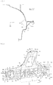
Fig. 1 is a perspective view of a main section of a vehicle having a vehicle side body structure seen from a right side of a vehicle body. -
Fig. 2 is a right side view illustrating the main section of the vehicle having the vehicle side body structure. -
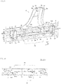
Fig. 3 is an enlarged view of the main section around a rear portion of a side sill from which a side sill inner is removed and which is viewed from a vehicle width inner side. -
Fig. 4(a) is an enlarged view of the main section in which a side sill outer and a rear wheel house are removed fromFig. 3, and Fig. 4(b) is an enlarged view of the main section in which a second reinforcing member is further removed therefrom. -
Fig. 5 is a cross-sectional view of the main section along line D-D inFig. 3 . -
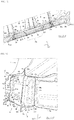
Fig. 6 is an enlarged view of the main section around the rear portion of the side sill inFig. 1 . -
Fig. 7 is a cross-sectional view of a main section along line E-E inFig. 6 . -
Fig. 8 is a perspective view in which the side sill inner is removed and a joined portion between the side sill and a center pillar and a portion therearound are seen from a vehicle width inner side. -
Fig. 9 is a perspective view in which a pillar inner is removed fromFig. 8 . -
Fig. 10 is a cross-sectional view illustrating the main section taken along line A-A inFig. 2 . -
Fig. 11 is a cross-sectional view illustrating the main section taken along line B-B inFig. 2 . -
Fig. 12 is a perspective cross-sectional view illustrating the main section of the vehicle side body structure and corresponding to an arrow direction of C-C inFig. 2 . - An exemplary description will hereinafter be made on aspects and embodiments of the present invention with reference to the drawings.
- In the drawings, an arrow F, an arrow U, and an arrow OUT respectively indicate a vehicle front direction, a vehicle up direction, and an outer side in a vehicle width direction (a vehicle right direction). In addition, in the following description, the outer side in the vehicle width direction (a cabin outer side) will be referred to as a "vehicle width outer side", and an inward direction in the vehicle width direction (a cabin inner side) will be referred to as a "vehicle width inner side". Note that a vehicle side body structure, which will be described below, is provided substantially and bilaterally symmetrical on left and right sides of a vehicle.
- As illustrated in
Fig. 1 ,side openings roof side rail 3 that extends substantially in a longitudinal direction is provided along upper sides of theside openings side sill 4 that extends substantially in the longitudinal direction is provided along lower sides of theside openings openings side sill 4 and thecenter pillar 5. - A
center pillar 5 that extends in a vertical direction (direction U in the Figures), i.e, an upward direction, is provided at an intermediate position between theside openings center pillar 5, an upper end is joined to an intermediate portion of theroof side rail 3, which extends in the vehicle longitudinal direction, and a lower end of thecenter pillar 5 is joined to an intermediate portion of theside sill 4, which extends in the vehicle longitudinal direction. - In this way, the
side openings center pillar 5 and are provided as getting-on/offopenings - The vehicle side body portion includes a side door (6) that opens/closes respective one of the front and rear getting-on/off
openings side door 6 is arranged to open/close theopenings 2r and/or 2f that are formed by the arrangement of theside sill 4 and the center pillar 5 (seeFigs. 1 and 2 ). InFig. 2 , the side door on a front side (a front side door) is not illustrated while theside door 6 on a rear side (a rear side door 6) is partially illustrated. - Accordingly, when the
door 6 is open, a vehicle user may access to the vehicle through theopening 2r/2f, while when thedoor 6 is closed, following a rotational movement about a hinge axis, the space defined by theopening 2r/2f is occupied by thedoor 6 thus the user cannot access to the vehicle. - The
rear side door 6 includes: adoor body 61 constructed of a door outer panel, a door inner panel, and the like; and a plurality of impact bars 63 extending in the vehicle longitudinal direction, when the door is mounted on the vehicle. A front end of therear side door 6 is supported by a portion on each of upper and lower sides of thecenter pillar 5 via an unillustrated hinge bracket. - The
door body 61 is provided with animpact bar reinforcement 64 that extends along a rear side, a front side, and a lower side thereof. - In the
door body 61, the impact bars 63 are provided at different heights from each other and are disposed between a front side and a rear side of theimpact bar reinforcement 64 so as to couple the front side and the rear side. -
Fig. 2 only illustrates animpact bar 63 that is located at a lowest position of the plurality of impact bars 63. A description will hereinafter be made on theimpact bar 63 that is located at the lowest position of the plurality of impact bars. - As illustrated in
Fig. 2 andFig. 5 , theimpact bar 63 is formed to have a substantially M-shaped cross section in a direction substantially perpendicular to a longitudinal direction (see in particularFig. 5 ). Theimpact bar 63 is formed with a front flange 63f and arear flange 63r, each of which is formed to be wider than an intermediate portion in the longitudinal direction, at front and rear ends. - In the
impact bar 63, by using joint tools such as bolts, the front flange 63f is fixed to a lower portion of the front side of theimpact bar reinforcement 64, and therear flange 63r is fixed to acorner portion 64c between a lower portion of the rear side and a lower side of theimpact bar reinforcement 64. - In this way, the
impact bar 63 is provided in a lower portion of therear side door 6 in a manner to be tilted upward to the front and downward to the rear. - Here, a joint position of the
rear flange 63r of theimpact bar 63 to the rear side of theimpact bar reinforcement 64 is located at a lower end of the lower portion of the rear side as described above, that is, thecorner portion 64c between the rear side and the lower side. - In this way, as illustrated in
Fig. 2 , when the rear getting-on/offopening 2r is closed by the rear side door 6 (hereinafter referred to as "when therear side door 6 is closed"), in theimpact bar 63, the front flange 63f of the impact bar 63 (that is, a joint portion to the front side of the impact bar reinforcement 64) overlaps thecenter pillar 5 in a vehicle side view, and, as illustrated inFig. 2 ,Fig. 3 , andFig. 5 , therear flange 63r of the impact bar 63 (that is, the joint portion to thecorner portion 64c between the rear side and the lower side of the impact bar reinforcement 64) overlaps a rear portion of theside sill 4 in the vehicle side view. A vehicle side view refers to a view along a direction being opposite to the direction OUT illustrated inFigs. 1 and 2 . - As illustrated in
Fig. 5 andFig. 12 , theside sill 4 is a vehicle body rigid member that has a closedcross-sectional space 4s. In other words, theside sill 4 is a vehicle body rigid member that, when assembled to a vehicle, is mounted on at least one lateral side of a vehicle. Theside sill 4 extends in the vehicle longitudinal direction, when the vehicle side body structure comprising theside sill 4 is mounted on a lateral side of a vehicle. In other words, when the vehicle side body structure is mounted on a vehicle, the longitudinal direction of theside sill 4 substantially corresponds to vehicle longitudinal direction. - The
side sill 4 may comprise afirst member 41, asecond member 42, and athird member 43 constituting the closedcross-sectional space 4s; and an exterior panel 44 (only illustrated inFig. 12 ) attached to the vehicle width outermost side of theside sill 4. - As a side sill inner 4i formed in a hat shape whose perpendicular cross section to the vehicle longitudinal direction is projected to the vehicle width inner side, the
first member 41 is provided on the vehicle width inner side of theside sill 4. In other words, with reference toFig. 5 , the side sill inner 4i of thefirst member 41 substantially protrudes to the vehicle width inner side along a direction substantially opposite to the "OUT" direction. More specifically, with reference toFig. 5 , thefirst member 41 may be integrally formed by including anupper end flange 41a extending in the vertical direction, anupper wall 41b extending to the vehicle width inner side from a lower end of theupper end flange 41a, aninner wall 41c extending downward from a vehicle width inner end of theupper wall 41b, alower wall 41d extending to the vehicle width outer side from a lower end of theinner wall 41c, and alower end flange 41e extending downward from a vehicle width outer end of thelower wall 41d. - As a side sill outer 4o formed in a hat shape whose perpendicular cross section to the vehicle longitudinal direction is projected to the vehicle width outer side, the
second member 42 and thethird member 43 are provided on the vehicle width outer side of thefirst member 41. - More specifically, the
second member 42 may be integrally formed by including anupper end flange 42a located in an upper portion of the side sill outer 4o and an intermediate portion in the vertical direction and extending in the vertical direction, anupper wall 42b extending to the vehicle width outer side from a lower end of theupper end flange 42a, anouter wall 42c extending downward from an vehicle width outer end of theupper wall 42b, and alower end flange 42d extending to the vehicle width inner side from a lower end of theouter wall 42c. Thethird member 43 is located in a lower portion of the side sill outer 4o and may be integrally formed by including alower wall 43a extending to the vehicle width inner side and alower end flange 43b extending downward from a vehicle width inner end of thelower wall 43a. - The
upper end flanges first member 41 and thesecond member 42 as well as thelower end flanges first member 41 and thethird member 43 may be integrally joined to each other by spot welding or the like. Furthermore, thelower end flange 42d of thesecond member 42 may be joined to thelower wall 43a of thethird member 43 from above (a side of the closedcross-sectional space 4s). - In this way, the
side sill 4 constitutes the closedcross-sectional space 4s therein by theupper wall 41b, theinner wall 41c, and thelower wall 41d of thefirst member 41, theupper wall 42b and theouter wall 42c of thesecond member 42, and thelower wall 43a of thethird member 43. In addition, in theside sill 4,ridgelines upper wall 42b and theouter wall 42c, theouter wall 42c and thelower end flange 42d, theupper wall 41b and theinner wall 41c, and theinner wall 41c and thelower wall 41d. Of theseridgelines ridgeline 45a defined between theupper wall 42b and theouter wall 42c, that is, theridgeline 45a defined at an upper end of theouter wall 42c is set as an upperouter ridgeline 45a, and theridgeline 45b defined between theouter wall 42c and thelower end flange 42d, that is, theridgeline 45b defined at the lower end of theouter wall 42c is set as a lowerouter ridgeline 45b. - In addition, as illustrated in
Fig. 5 andFig. 12 , theouter wall 42c of theside sill 4 is provided with an outer wall bead 42cc, which is dented to the side of the closedcross-sectional space 4s, near a center in the vertical direction. - Furthermore, as illustrated in
Fig. 5, Fig. 6 , andFig. 12 , thethird member 43 is further formed with a vehicle widthouter end flange 43c extending to the vehicle width outer side from a vehicle width outer end of thelower wall 43a. When mounted on a vehicle, the vehicle widthouter end flange 43c extends to the vehicle width outer side from an upper end portion of an overlappingportion 46 between thelower end flange 42d of thesecond member 42 and thelower wall 43a of thethird member 43. - In a cross-sectional view that is perpendicular to the longitudinal direction of the
side sill 4, the vehicle widthouter end flange 43c is projected downward and to the vehicle width outer side from a position between theouter wall 42c and thelower wall 43a of theside sill 4 in a manner to be bent from theseouter wall 42c andlower wall 43a. In this way, a ridgeline 43cc extending substantially in the vehicle longitudinal direction is defined in a base end portion of the vehicle widthouter end flange 43c. - In the cross-sectional view that is perpendicular to the longitudinal direction of the
side sill 4, this ridgeline 43cc may match or may be located near the above-described lowerouter ridgeline 45b. In the present example, the ridgeline 43cc located in the base end portion of the vehicle widthouter end flange 43c is located below and near the lowerouter ridgeline 45b. - Moreover, as illustrated in
Fig. 9 , thelower wall 43a of thethird member 43 in theside sill 4 may comprise a plurality of throughholes 47, each of which has a substantially circular shape in a plan view, along the vehicle longitudinal direction. When mounted on a vehicle, a longitudinal direction of theside sill 4 substantially corresponds to the vehicle longitudinal direction. Each of these throughholes 47 may be used to insert a corrosion inhibitor spray gun (not illustrated) in the closedcross-sectional space 4s in order to introduce an electrodeposition liquid or the like into the closedcross-sectional space 4s of theside sill 4 or spraying a corrosion inhibitor on an inner surface that is a surface facing the closedcross-sectional space 4s of theside sill 4. - By the way, as illustrated in
Fig. 12 , afloor panel 100 that forms an unillustrated tunnel portion raised upward in a central portion in the vehicle width direction and extending in the vehicle longitudinal direction is stretched between the above-describedside sills 4 on both sides in a vehicle body lower portion, when bothside sills 4 are mounted on both sides of the vehicle. Furthermore, as illustrated inFig. 11 , in a rear end portion of thefloor panel 100, a kick-upportion 101 is provided in a manner to be raised upward from the rear end portion. - As illustrated in
Fig. 11 and Fig. 12 , a front crossmember 110 (2.0 crossmember) and an intermediate crossmember 120 (2.5 crossmember), each of which extends in the vehicle width direction and couples theside sill 4 and the tunnel section, are disposed on an upper surface of thefloor panel 100 on both sides of the tunnel section. In a cross-sectional view that is perpendicular to the vehicle longitudinal direction, each of thefront crossmember 110 and theintermediate crossmember 120 is formed in a hat shape that is opened downward and, with thefloor panel 100, constitutes a closed cross-sectional space extending in the vehicle width direction. - Furthermore, in an upper portion of the kick-up
portion 101, a rear crossmember 130 (3.0 crossmember) that is joined and fixed to the upper portion from a back surface side and has a closed cross-sectional space extending in the vehicle width direction is disposed. - These
crossmembers front crossmember 110 is disposed to be located in an intermediate portion of the front getting-on/off opening 2f, theintermediate crossmember 120 is disposed to be located on thecenter pillar 5, and therear crossmember 130 is disposed to be located in an intermediate portion of the rear getting-on/off opening 2r. - As illustrated in
Fig. 11 ,flanges crossmembers inner wall 41c of theside sill 4, and each of thesecrossmembers side sill 4. - As illustrated in
Fig. 1 to Fig. 3 , arear wheel house 90 that forms a lower portion of a rear side of the rear getting-on/off opening 2r from a rear portion of a lower side thereof is disposed behind theside sill 4. As illustrated inFig. 7 , therear wheel house 90 includes a rear wheel house inner 91 and a rear wheel house outer 92, each of which is formed in an arch shape and projected upward in a vehicle side view, and these accommodate a rear wheel from above. - As illustrated in
Fig. 3 andFig. 11 , a frontlower portion 92a of the rear wheel house outer 92 is joined to a rear end of theside sill 4. In other words, the frontlower portion 92a of the rear wheel house outer 92 extends substantially from the rear portion of theside sill 4 in an upward direction. The upward direction may substantially correspond to the vehicle up direction U. - As illustrated in
Fig. 9 to Fig. 12 , theside sill 4 includes a plurality of sections (partition walls), namelysections cross-sectional space 4s in the vehicle longitudinal direction. - The
plural sections side sill 4. In the present example, theplural sections side sill 4. - Note that the center pillar arrangement region 4Ra is located in the intermediate portion of the
side sill 4 in the vehicle longitudinal direction. - These
sections forward section 21F, a pillarfront section 22F, a pillarrear section 22R, and a pillarrearward section 21R in an order from a front side to a rear side. - As illustrated in
Fig. 9 and Fig. 10 , each of the pillarfront section 22F and the pillarrear section 22R includes avertical wall 22a that partitions the closedcross-sectional space 4s in the vehicle longitudinal direction. In addition, as illustrated inFig. 9, Fig. 10 ,Fig. 11, and Fig. 12 , each of the pillarforward section 21F and the pillar rearwardsection 21R is constructed of anouter section component 23 located on the vehicle width outer side and aninner section component 24 located on the vehicle width inner side. - As illustrated in
Fig. 10 , theouter section component 23 includes afront wall 23a and arear wall 23b that are separately disposed along the vehicle longitudinal direction, and theinner section component 24 includes avertical wall 24a extending in the vertical direction and the vehicle width direction. - The above-described pillar
front section 22F partitions the vehicle width outer side of the closedcross-sectional space 4s by thevertical wall 22a. The pillarforward section 21F partitions the vehicle width outer side of the closedcross-sectional space 4s by thefront wall 23a and therear wall 23b provided in theouter section component 23, and partitions the vehicle width inner side of the closedcross-sectional space 4s by thevertical wall 24a provided in theinner section component 24. - The side sill outer 4o, which is constructed of the
second member 42 and thethird member 43, is provided with first reinforcingmembers member 31 configured to reinforce a bending rigidity against a load directed to the vehicle width inner side, e.g., in case of a lateral collision. - As illustrated in
Fig. 5 ,Fig. 9 , andFig. 12 , the first reinforcingmembers upper reinforcing member 30U located in an upper portion of theside sill 4 and a first lower reinforcingmember 30D located in a lower portion of theside sill 4. - As illustrated in
Fig. 5 ,Fig. 8 ,Fig. 9 , andFig. 12 , in the vertical direction of theouter wall 42c of theside sill 4, an outer wall bead 42cc may be provided at an intermediate position in the vertical direction located between the firstupper reinforcing member 30U and the first lower reinforcingmember 30D. - As illustrated in
Fig. 9 to Fig. 11 , the firstupper reinforcing member 30U may be joined to theside sill 4 at a height position of a center pillar joinedportion 4A. - The first
upper reinforcing member 30U may be integrally formed substantially in an L-shape in the cross-sectional view that is perpendicular to the vehicle longitudinal direction by a lateral side 33 (seeFig. 11 and Fig. 12 ) extending in the vehicle width direction along theupper wall 42b of thesecond member 42 in theside sill 4 and avertical side 34 extending downward from a vehicle width outer end of thelateral side 33. - The first
upper reinforcing member 30U is partially provided in the cross-sectional view that is perpendicular to the longitudinal direction of theside sill 4. - In detail, as illustrated in
Fig. 5 andFig. 12 , the firstupper reinforcing member 30U may be joined to theside sill 4 in a manner to only cover the single ridgeline (theridgeline 45a in the present example) among the plural (four in the present example)ridgelines side sill 4. - Further in detail, as illustrated in the same drawings, in a corner portion between the
upper wall 42b and theouter wall 42c of thesecond member 42 in theside sill 4, thelateral side 33 and thevertical side 34 of the firstupper reinforcing member 30U are respectively arranged on theupper wall 42b of thesecond member 42 and theouter wall 42c of thesecond member 42 from the side of the closedcross-sectional space 4s such that aridgeline 35 provided between thelateral side 33 and thevertical side 34 abuts the upperouter ridgeline 45a provided in the corner portion, and the firstupper reinforcing member 30U may be joined at a plurality of positions substantially along the vehicle longitudinal direction by welding or the like. - As illustrated in
Fig. 1, Fig. 2 ,Fig. 10 , andFig. 12 , the first lower reinforcingmember 30D may be joined to theside sill 4 at a position lower than the height position of the center pillar joinedportion 4A. In detail, as illustrated inFig. 12 , the first lower reinforcingmember 30D may be integrally formed substantially in an L-shape in the cross-sectional view that is perpendicular to the vehicle longitudinal direction by alateral side 36 extending in the vehicle width direction along thelower wall 41d of thethird member 43 in theside sill 4 and avertical side 37 extending upward from a vehicle width outer end of thelateral side 36. In a corner portion between theouter wall 42c of thesecond member 42 and thelower wall 43a of thethird member 43 in theside sill 4, thevertical side 37 and thelateral side 36 of the first lower reinforcingmember 30D may be respectively joined to theouter wall 42c of thesecond member 42 and thelower wall 43a of thethird member 43 via thelower end flange 42d of thesecond member 42 at plural positions from the side of the closedcross-sectional space 4s along substantially the vehicle longitudinal direction by welding or the like such that aridgeline 38 between thevertical side 37 and thelateral side 36 abuts the lowerouter ridgeline 45b provided in the corner portion. - As illustrated in
Fig. 3 ,Fig. 5 , andFig. 9 toFig. 12 , these first upper reinforcingmember 30U and first lower reinforcingmember 30D may extend continuously in the vehicle longitudinal direction from a position in front of thecenter pillar 5 to the rear portion of theside sill 4 in a manner to cross thecenter pillar 5 along the longitudinal direction of theside sill 4. - The first
upper reinforcing member 30U will be described in detail. A front end of the firstupper reinforcing member 30U may extend to a position in front of the pillarforward section 21F as illustrated inFig. 9 to Fig. 11 and may also extend to a position where the firstupper reinforcing member 30U overlaps thefront crossmember 110 in the vehicle side view as illustrated inFig. 11 . - A rear end of the first
upper reinforcing member 30U may extend to a position behind the pillar rearwardsection 21R as illustrated inFig. 9 andFig. 11 , and may also extends to a position behind therear crossmember 130 as illustrated inFig. 11 . - That is, in the vehicle longitudinal direction, first upper reinforcing
member 30U may be provided in a manner to cross the pillarforward section 21F, the pillarfront section 22F, the pillarrear section 22R, and the pillar rearwardsection 21R, and is also provided in a manner to cross thecrossmembers - As illustrated in
Fig. 1 ,Fig. 3 ,Fig. 4(a) , andFig. 5 toFig. 7 , the above-described second reinforcingmember 31 may be provided in the rear portion of theside sill 4 and extends upward from the rear portion of theside sill 4 and along therear wheel house 90. - As illustrated in
Fig. 6 , the second reinforcingmember 31 includes an upward extendingportion 31u extending upward and a forward extendingsection 31f extending forward. As illustrated inFig. 5 to Fig. 7 , in a corner portion between the frontlower portion 92a of the rear wheel house outer 92 and the rear portion of theside sill 4 in the vehicle side view, the upward extendingsection 31u and theforward extending section 31f are respectively joined to the frontlower portion 92a of the rear wheel house outer 92 and the rear portion of theside sill 4 by welding or the like. - In other words, as illustrated in
Fig. 4(a) ,Fig. 5 ,Fig. 6 , andFig. 7 , the second reinforcingmember 31 may be integrally formed in a substantially triangular shape in the vehicle side view. More particularly, the second reinforcingmember 31 may comprise aside wall 31a extending in the vertical direction and the vehicle longitudinal direction, avertical wall 31b extending to the vehicle width inner side from an upper edge of theside wall 31a, and aflange 31c extending upward from a vehicle width inner end of thevertical wall 31b. - In the second reinforcing
member 31,ridgelines member 31 are respectively defined between theside wall 31a and thevertical wall 31b and between thevertical wall 31b and theflange 31c. Theseridgelines portion 31u, and extend substantially along the vehicle longitudinal direction in theforward extending section 31f. - As illustrated in
Fig. 6 , the forward extendingsection 31f of the second reinforcingmember 31 is joined to the rear portion and the upper portion of theside sill 4 from the vehicle width outer side. More specifically, as illustrated inFig. 5 and Fig. 6 , in the second reinforcingmember 31, theflange 31c of theforward extending section 31f and theside wall 31a of theforward extending section 31f are respectively joined to theupper end flange 42a of thesecond member 42 and theouter wall 42c of thesecond member 42 in theside sill 4 in a manner to cover theupper end flange 42a and theouter wall 42c from the vehicle width outer side, and thevertical wall 31b of theforward extending section 31f is joined to theupper wall 42b of thesecond member 42 in a manner to cover theupper wall 42b from above. - In this way, as illustrated in
Fig. 3, Figs. 4(a), (b) , andFig. 5 , in the rear portion of theside sill 4, a front portion of the second reinforcingmember 31, that is, the forward extendingsection 31f is located on the vehicle width outer side of a rear portion of the firstupper reinforcing member 30U and overlaps the rear portion of the firstupper reinforcing member 30U in the vehicle side view (that is, in the vehicle width direction). - Furthermore, as illustrated in
Fig. 3, Fig. 4(a) , andFig. 5 , in the rear portion of theside sill 4, the second reinforcingmember 31 overlaps therear end flange 63r of theimpact bar 63 in the vehicle side view. - More specifically, when the
rear side door 6 is closed, i.e., when the door is in a closed configuration, as described above, therear end flange 63r of theimpact bar 63, which is provided in the lower portion of therear side door 6, is configured to overlap the rear portion of theside sill 4 in the vehicle side view. Accordingly, as illustrated inFig. 3, Figs. 4(a), (b) , andFig. 5 , in the rear portion of theside sill 4, therear end flange 63r of theimpact bar 63, the forward extendingsection 31f of the second reinforcingmember 31, thesecond member 42 of theside sill 4, and the rear portion of the firstupper reinforcing member 30U are sequentially provided from the outer side to the inner side in the vehicle width direction, and these overlap each other in the vehicle side view. - In the present example, in an overlapping portion of the second reinforcing
member 31, thesecond member 42 of theside sill 4, and the firstupper reinforcing member 30U, these three pieces are integrally joined to each other by spot welding. InFig. 3 and Fig. 4(a) , "×" represents joined positions wa, wb. - In other words, as illustrated in
Fig. 5 , the second reinforcingmember 31 and the firstupper reinforcing member 30U are joined to each other at the joined positions wa, wb in a manner to hold thesecond member 42 of theside sill 4 therebetween. - As illustrated in
Fig. 4(a) , therear end flange 63r of theimpact bar 63 overlaps the joined portion (at least the joined position wa) between the second reinforcingmember 31 and the firstupper reinforcing member 30U in the vehicle side view. - In addition, as illustrated in
Fig. 5 andFig. 12 , theridgeline 35 defined between thelateral side 33 and thevertical side 34 of the firstupper reinforcing member 30U extends substantially for an entire length of the firstupper reinforcing member 30U in the vehicle longitudinal direction. - Meanwhile, as illustrated in
Fig. 4(a) andFig. 6 , as described above, theridgelines member 31 may extend substantially along the vertical direction in the upward extendingportion 31u located in the rear portion of the second reinforcingmember 31, and may extend substantially along the vehicle longitudinal direction in theforward extending section 31f positioned in the front portion of the second reinforcingmember 31. - In the present example, the rear portion of the
ridgeline 35 extending substantially in the longitudinal direction and the lower portions (front portions) of theridgelines Fig. 4(a) ,Fig. 5 ,Fig. 6 , andFig. 12 ). - As illustrated in
Fig. 1 ,Fig. 8 , andFig. 9 , the above-describedcenter pillar 5 includes a pillar inner 51 and a pillar outer 52. Thecenter pillar 5 is substantially vertically provided in theside sill 4 by welding lower portions of these to theside sill 4. The lower portion of the center pillar 5 (a root region for the side sill 4) is formed such that a width thereof is gradually increased downward in the vehicle longitudinal direction from a portion of the lower portion near anupper end 52a (seeFig. 1, Fig. 2 , andFig. 9 ) to the upper end of theside sill 4. - As illustrated in
Fig. 8 , the pillar inner 51 may be formed in a vertical wall shape (a substantially flat plate shape) in which a substantially entire portion in the vertical direction extends in the vehicle width direction, and may be formed with aflange 51d on each of front and rear sides thereof. - As illustrated in
Fig. 1 ,Fig. 8 , andFig. 9 , the pillar outer 52 may be integrally formed by including anouter wall 52b extending in the vertical direction and the vehicle width direction, front and rearvertical walls 52c extending to the vehicle width inner side from front and rear ends of theouter wall 52b, aflange 52d on each of the front and rear sides formed along thevertical wall 52c such that the substantially entire portion in the vertical direction has a hat-shaped cross-sectional shape opened to the vehicle width inner side in the cross-sectional view that is perpendicular to the vertical direction. - The
center pillar 5 is configured to have a closed cross-sectional space 5s extending in the vertical direction between the pillar inner 51 and the pillar outer 52 by joining thefront edge flanges rear edge flanges - A lower portion of the pillar outer 52 is joined to the
second member 42 of theside sill 4, and this joint structure will be described. - As illustrated in
Fig. 1, Fig. 2 , andFig. 10 , the lower portion of the pillar outer 52 is formed with alower end flange 52e extending downward from a lower end of theouter wall 52b, and thislower end flange 52e is joined to theouter wall 42c of thesecond member 42 in theside sill 4. In this way, as illustrated inFig. 1 andFig. 10 , thecenter pillar 5 and theside sill 4 are arranged such that theouter wall 52b and theouter wall 42c are substantially flush in the vehicle width direction, when the vehicle side body structure is mounted on a side of a vehicle. In addition, each of the front andrear flanges 52d of the pillar outer 52 and each of the front andrear flanges 51d of the pillar inner 51 are integrally joined to each other as described above. As illustrated inFig. 8 , lower portions of theflanges upper end flange 42a of thesecond member 42 on a side of the side sill outer 4o from both of the inner and outer sides in the vehicle width direction. In this way, each of the front andrear flanges center pillar 5 and theupper end flange 42a of theside sill 4 are arranged to be substantially flush in the vehicle width direction. - In this state, as illustrated in
Fig. 1 , thevertical wall 52c on each of the front and rear sides of the pillar outer 52 is brought into a state where a lower end thereof contacts theupper wall 42b of thesecond member 42 in theside sill 4, and thevertical wall 52c extending in the vertical direction on each of the front and rear sides and theupper wall 42b extending in the longitudinal direction in thesecond member 42 of theside sill 4 continuously and smoothly extend in a corner portion of these in the vehicle side view. - The pillar inner 51 is formed such that the lower portion is widened in the vehicle longitudinal direction so as to correspond to the lower portion of the pillar outer 52, and forms an extending
portion 55 that extends to be lower than an upper end position of theside sill 4. - More specifically, in the center pillar arrangement region 4Ra along the vehicle longitudinal direction of the
side sill 4, as illustrated inFig. 8 andFig. 10 , the extendingportion 55 is disposed in the closedcross-sectional space 4s in a manner to partition the closedcross-sectional space 4s into spaces on the inner and outer sides in the vehicle width direction. As illustrated inFig. 8 , an upper end 55u of the extendingportion 55 is interposed between theupper end flanges first member 41 and thesecond member 42 in theside sill 4 and is integrally joined to theseupper end flanges lower end 55d of the extendingportion 55 is interposed between thelower end flanges first member 41 and thethird member 43 in theside sill 4 and is integrally joined to theselower end flanges - Note that, as described above, the lower portion of the pillar inner 51 including the extending
portion 55 is formed to be wide in the vehicle longitudinal direction. - In addition, as illustrated in
Fig. 8 , the pillar inner 51 has a pillar inner upper 56 and a pillar inner lower 57 provided below the pillar inner upper 56. A lower portion of the pillar inner upper 56 and an upper portion of the pillar inner lower 57 overlap each other in the vehicle width direction in the closedcross-sectional space 4s of theside sill 4. That is, as illustrated inFig. 8 andFig. 10 , an overlappingportion 58 between the lower portion of the pillar inner upper 56 and the upper portion of the pillar inner lower 57 is provided in the above-described extendingportion 55, and the lower portion of the pillar inner upper 56 and the upper portion of the pillar inner lower 57 are joined to each other at plural positions along the vehicle longitudinal direction of the extendingportion 55 by spot welding or the like (see "×" inFig. 8 ). - As illustrated in
Fig. 10 , in the closedcross-sectional space 4s of theside sill 4, the pillarfront section 22F and the pillarrear section 22R described above are provided on the vehicle width outer side of the extendingportion 55, and the pillarfront section 22F and the pillarrear section 22R are respectively provided on a front end side of the extendingportion 55 and a rear end side of the extendingportion 55 in a manner to be separated from each other in the vehicle longitudinal direction. - As illustrated in
Fig. 1 and Fig. 2 , the vehicle side body structure according to the embodiment described above is the vehicle side body structure that includes: theside sill 4 that has the closedcross-sectional space 4s (seeFig. 10 ) (the closed cross-sectional structure). When the vehicle side body structure is mounted on a side of a vehicle, theside sill 4 extends in the vehicle longitudinal direction. Thewheel house 90 comprises a frontlower portion 92a raised from the rear portion of theside sill 4. In other words, the frontlower portion 92a extends from the rear portion of theside sill 4. Thecenter pillar 5 has a closed cross-sectional space 5s (the closed cross-sectional structure) (seeFig. 8 ) and extends substantially in an upward direction from the intermediate portion of theside sill 4. A rear side door 6 (seeFig. 2 ) serves as the door for opening/closing the rear getting-on/off opening 2r that is the opening formed to be opened at the position above theside sill 4 and behind thecenter pillar 5. More particularly, the rear getting-on/offopening 2r is the opening formed between theside sill 4 and thecenter pillar 5. - Referring to
Figs. 1 and 2 , a position above theside sill 4 may be a position above theside sill 4 in a vehicle up direction (direction U), while a position behind thecenter pillar 5 may be a position behind thecenter pillar 5 along a direction being opposite to a vehicle front direction (direction F). - As illustrated in
Fig. 2 , thedoor 6 comprises animpact bar 63 that is disposed such that, when therear side door 6 is closed therear flange 63r (the rear portion) of theimpact bar 63 provided to therear side door 6 overlaps the rear portion of theside sill 4 in a vehicle side view (that is, in the vehicle width direction). As illustrated inFig. 3, Figs. 4(a), (b) ,Fig. 5 , andFig. 9 toFig. 11 , theside sill 4 includes a firstupper reinforcing member 30U as the side sill reinforcing member configured to reinforce the bending rigidity against a load that may be directed to the vehicle width inner side, when the vehicle side body structure is mounted on a side of a vehicle, for example in case of a lateral collision. The firstupper reinforcing member 30U is provided at least in the intermediate portion (the center pillar arrangement region 4Ra) of theside sill 4, in which at least thecenter pillar 5 is located, and in the longitudinal direction of theside sill 4 as illustrated inFig. 9 to Fig. 11 , and is provided in the rear portion of theside sill 4 as illustrated inFig. 3 andFig. 11 . - With the above configuration, the
rear flange 63r of theimpact bar 63 provided to therear side door 6 is disposed to overlap the rear portion of theside sill 4 in the vehicle side view at the time when therear side door 6 is closed, and theside sill 4 including the rear portion thereof is reinforced by the firstupper reinforcing member 30U. Thus, the rear portion of theside sill 4 can securely receive a lateral collision load that is applied to theimpact bar 63 of therear side door 6 during the lateral collision of the vehicle (hereinafter referred to as "during the lateral collision"). - Furthermore, since the front
lower portion 92a of therear wheel house 90 is raised from the rear portion of the side sill 4 (seeFig. 1 andFig. 3 ), the rear portion of the side sill forms the L-shaped region in the vehicle side view with the frontlower portion 92a of the rear wheel house 90 (the rear wheel house outer 92), and the L-shaped region can receive the load that is transmitted from theimpact bar 63 to the rear portion of theside sill 4 during the lateral collision while dispersing the load. In other words, since the frontlower portion 92a of therear wheel house 90 is joined to the rear portion of theside sill 4 and substantially extends in an upward direction from the rear portion of theside sill 4, the rear portion of theside sill 4 forms the L-shaped region in the vehicle side view with the frontlower portion 92a of the rear wheel house 90 (the rear wheel house outer 92), and the L-shaped region can receive the load that is transmitted from theimpact bar 63 to the rear portion of theside sill 4 during the lateral collision while dispersing the load. - Just as described, with the
rear wheel house 90 as a vehicle body part, the firstupper reinforcing member 30U effectively receives the lateral collision load. Thus, compared to a case where the firstupper reinforcing member 30U receives the lateral collision load by itself, the structure of the firstupper reinforcing member 30U can be simplified. As a result, weight of the firstupper reinforcing member 30U can be reduced. - In summary, with the above configuration, the first
upper reinforcing member 30U is at least provided in the intermediate portion (4Ra) of the side sill and the rear portion of theside sill 4 in the longitudinal direction of theside sill 4. Thus, it is possible to securely receive the lateral collision load when the lateral collision load is transmitted in the dispersed manner to the intermediate portion (4Ra) of the side sill via thecenter pillar 5 and to the rear portion of theside sill 4 via theimpact bar 63. - Therefore, it is possible to improve the bending rigidity of the
side sill 4 against the load directed to the vehicle width inner side during the lateral collision while suppressing a weight increase of the vehicle body (the side sill 4). - Here, as long as the configuration that the first
upper reinforcing member 30U is at least provided in the center pillar arrangement region 4Ra and the rear portion in the longitudinal direction of theside sill 4 is adopted, the firstupper reinforcing member 30U may be provided discontinuously such that these center pillar arrangement region 4Ra and rear portion are separated (not illustrated) . However, as in the present example, when the firstupper reinforcing member 30U is continuously provided from the center pillar arrangement region 4Ra to the rear portion of theside sill 4 along the longitudinal direction of the side sill 4 (seeFig. 11 ), the firstupper reinforcing member 30U can disperse the load, which is transmitted from theimpact bar 63 to the rear portion of theside sill 4, from the rear portion of theside sill 4 to the center pillar arrangement region 4Ra during the lateral collision. Thus, such a configuration is preferred in terms of a point that an effect of reinforcing theside sill 4 by the firstupper reinforcing member 30U can be enhanced. - Furthermore, in such a case, as in the present example, the configuration that, in the cross-sectional view that is perpendicular to the longitudinal direction of the
side sill 4, the firstupper reinforcing member 30U is partially provided only to the upper portion corresponding to the height of the center pillar joinedportion 4A, to which thecenter pillar 5 is joined, (seeFig. 5 andFig. 12 ) and is thereby continuously provided along the longitudinal direction of theside sill 4 is further preferred in terms of a point that a weight increase of theside sill 4 can be suppressed. - As an aspect of the present invention, the second reinforcing member 31 (the wheel house reinforcing member) that substantially extends in an upward direction, from the rear portion of the
side sill 4 and along therear wheel house 90 is provided. Additionally, the second reinforcingmember 31 may be arranged to overlap the firstupper reinforcing member 30U in the region where therear flange 63r (the rear portion) of theimpact bar 63 is located in the vehicle side view (that is, in the vehicle width direction) (seeFig. 4(a) andFig. 5 ). - With the above configuration, it is possible to securely receive the lateral collision load that is transmitted from the
impact bar 63 to the rear portion of theside sill 4 during the lateral collision by the overlapping portion between the firstupper reinforcing member 30U and the second reinforcingmember 31. - As an aspect of the present invention, the second reinforcing
member 31 may be joined to the firstupper reinforcing member 30U. Moreover, when thedoor 6 is in a closed configuration, therear flange 63r of theimpact bar 63 may be arranged to overlap the portion where the second reinforcingmember 31 and the firstupper reinforcing member 30U are joined to each other in the vehicle side view (seeFig. 3 and Fig. 4(a) ). With the above configuration, it is possible to further securely receive the lateral collision load that is applied to theimpact bar 63 of therear side door 6 during the lateral collision by the rear portion of theside sill 4. - As an aspect of the present invention, the first
upper reinforcing member 30U may comprise aridgeline 35 extending substantially in the vehicle longitudinal direction (seeFig. 5 ,Fig. 11, and Fig. 12 ), and the second reinforcingmember 31 may comprise aridgelines Fig. 5 to Fig. 7 ). The firstupper reinforcing member 30U and the second reinforcingmember 31 may be formed such that theridgeline 35 extending substantially in the vehicle longitudinal direction and theridgelines - With the above configuration, since the first
upper reinforcing member 30U has theridgeline 35 extending substantially in the vehicle longitudinal direction, it is possible to further improve the bending rigidity against the load to the vehicle width inner side of theside sill 4 in the vehicle plan view. - Furthermore, since the second reinforcing
member 31 has theridgelines side sill 4 in the vehicle side view and torsion rigidity around an axis extending in the longitudinal direction of theside sill 4. - If these
ridgelines side sill 4 against the load to the inner side in the vehicle width direction during the lateral collision. - As an aspect of the present invention, the
impact bar 63 may be arranged to overlap thecenter pillar 5 in the vehicle side view (that is, in the vehicle width direction) (seeFig. 2 ). - With the above configuration, when the
rear side door 6 is closed, the front flange 63f (the front portion) of theimpact bar 63 overlaps thecenter pillar 5 in the vehicle side view. Accordingly, it is possible to securely transmit the lateral collision load, which is received by thecenter pillar 5 from a colliding object during the lateral collision, to the rear portion of theside sill 4 via theimpact bar 63, and it is also possible to securely transmit the lateral collision load, which is received by theimpact bar 63 from the colliding object, to the center pillar arrangement region 4Ra of theside sill 4 via thecenter pillar 5. - Thus, for example, compared to a configuration that only a region where the
center pillar 5 is located or the like is formed to be strong, it is possible to improve the bending rigidity against the load to the inner side in the vehicle width direction received by theside sill 4 while suppressing the weight increase of theside sill 4. - As an aspect of the present invention, the side sill reinforcing member may include a first
upper reinforcing member 30U (the upper reinforcing member) located in the upper portion of theside sill 4 and a first lower reinforcingmember 30D (the lower reinforcing member) located in the lower portion of theside sill 4. In theside sill 4, an outer wall bead 42cc may be provided in theouter wall 42c that is located in the intermediate portion in the vertical direction between these first upper reinforcingmember 30U and first lower reinforcingmember 30D (seeFig. 5 ,Fig. 8 ,Fig. 9 , andFig. 12 ). - With the above configuration, it is possible to further improve the bending rigidity of the
side sill 4 against the load to the inner side in the vehicle width direction during the lateral collision. - Finally, a further aspect of the present invention relates to a vehicle comprising the vehicle side body structure mounted on a lateral side and/or both lateral sides of the vehicle.
- The present invention is not limited to the configuration in the above-described embodiment, but can be implemented in various embodiments.
Claims (12)
- A vehicle side body structure comprising:a side sill (4) having a substantially closed cross-sectional structure extending in a vehicle longitudinal direction;a wheel house (90) comprising a front lower portion (92a) raised from a rear portion of said side sill (4);a center pillar (5) having a substantially closed cross-sectional structure extending in a substantially upward direction from an intermediate portion of the side sill (4); anda door (6) arranged to open/close an opening (2r) formed at a position above the side sill (4) and behind the center pillar (5), wherein the door (6) comprises an impact bar (63), wherein the impact bar (63) is disposed such that a rear portion (63r) of the impact bar (63) overlaps the rear portion of the side sill (4) in a vehicle side view when said door (6) is closed,wherein the side sill (4) includes a side sill reinforcing member (30U) configured to reinforce a bending rigidity against a load to an inner side in a vehicle width direction, andwherein the side sill reinforcing member (30U) is at least provided in an intermediate portion of the side sill (4Ra), in which the center pillar (5) is located, and in the rear portion of the side sill (4) in a longitudinal direction of the side sill.
- The vehicle side body structure according to claim 1 further comprising:
a wheel house reinforcing member (31) that extends in a substantially upward direction from the rear portion of the side sill (4) and along the wheel house (90). - The vehicle side body structure according to claim 2, wherein the wheel house reinforcing member (31) is arranged to overlap the side sill reinforcing member (30U) in or near a region where a rear portion (63r) of the impact bar (63) is located, in the vehicle side view.
- The vehicle side body structure according to any one of the preceding claims, wherein
the wheel house reinforcing member (31) is joined to the side sill reinforcing member (30U). - The vehicle side body structure according to claim 4, wherein, the rear portion (63r) of the impact bar (63) overlaps a joined portion between the wheel house reinforcing member (31) and the side sill reinforcing member (30U) in the vehicle side view.
- The vehicle side body structure according to any one of the preceding claims, wherein the side sill reinforcing member (30U) and the wheel house reinforcing member (31) have a ridgeline (35) extending substantially in the vehicle longitudinal direction and a ridgeline (31d, 31e) extending substantially in a vertical direction, respectively.
- The vehicle side body structure according to claim 6, wherein the ridgeline (35) extending substantially in the vehicle longitudinal direction and the ridgeline (31d, 31e) extending substantially in the vertical direction are continuous in the vehicle side view.
- The vehicle side body structure according to any one of the preceding claims, wherein the impact bar (63) is arranged to overlap the center pillar (5) in the vehicle side view.
- The vehicle side body structure according to any one of the preceding claims, wherein the side sill reinforcing member (30U) comprises an upper reinforcing member (30U) located in an upper portion of the side sill (4) and a lower reinforcing member (30D) located in a lower portion of the side sill (4).
- The vehicle side body structure according to claim 9, wherein an outer wall bead (42cc) is provided in an outer wall (4O) of the side sill (4), wherein the outer wall bead (42cc) is located in an intermediate portion between the upper reinforcing member (30U) and the lower reinforcing member (30D) in the vertical direction.
- The vehicle side body structure according to any one of claims 9 and 10, wherein the upper reinforcing member (30U) and the lower reinforcing member (30D) extend continuously in the vehicle longitudinal direction, from a position in front of the center pillar (5) to the rear portion of the side sill (4) so as to cross the center pillar (5) along the longitudinal direction of the side sill (4).
- A vehicle comprising the vehicle side body structure according to any one of claims 1 to 11.
Applications Claiming Priority (1)
| Application Number | Priority Date | Filing Date | Title |
|---|---|---|---|
| JP2019112694A JP7354606B2 (en) | 2019-06-18 | 2019-06-18 | Side body structure |
Publications (1)
| Publication Number | Publication Date |
|---|---|
| EP3753812A1 true EP3753812A1 (en) | 2020-12-23 |
Family
ID=69804772
Family Applications (1)
| Application Number | Title | Priority Date | Filing Date |
|---|---|---|---|
| EP20162592.8A Withdrawn EP3753812A1 (en) | 2019-06-18 | 2020-03-12 | Vehicle side body structure |
Country Status (4)
| Country | Link |
|---|---|
| US (1) | US11279411B2 (en) |
| EP (1) | EP3753812A1 (en) |
| JP (1) | JP7354606B2 (en) |
| CN (1) | CN112092915B (en) |
Cited By (1)
| Publication number | Priority date | Publication date | Assignee | Title |
|---|---|---|---|---|
| FR3124477A1 (en) * | 2021-06-23 | 2022-12-30 | Psa Automobiles Sa | Reinforced beam for motor vehicle |
Families Citing this family (2)
| Publication number | Priority date | Publication date | Assignee | Title |
|---|---|---|---|---|
| JP7414765B2 (en) * | 2021-03-29 | 2024-01-16 | トヨタ自動車株式会社 | vehicle |
| KR20240003976A (en) * | 2022-07-04 | 2024-01-11 | 현대자동차주식회사 | Vehicle side structure |
Citations (4)
| Publication number | Priority date | Publication date | Assignee | Title |
|---|---|---|---|---|
| JP2009173142A (en) * | 2008-01-23 | 2009-08-06 | Mazda Motor Corp | Side shock absorption structure of vehicle |
| US20110169302A1 (en) * | 2010-01-09 | 2011-07-14 | Ford Global Technologies, Llc | Door block arrangement for energy absorbing vehicle door |
| DE202014105787U1 (en) * | 2013-12-04 | 2014-12-15 | Ford Global Technologies, Llc | Door bracket for reducing indentations |
| JP2018118697A (en) | 2017-01-27 | 2018-08-02 | マツダ株式会社 | Side-part vehicle body structure for vehicle |
Family Cites Families (7)
| Publication number | Priority date | Publication date | Assignee | Title |
|---|---|---|---|---|
| JP4196596B2 (en) * | 2002-06-17 | 2008-12-17 | 日産自動車株式会社 | Car door intrusion prevention structure |
| JP4848911B2 (en) * | 2006-09-28 | 2011-12-28 | マツダ株式会社 | Car side body structure |
| JP5427895B2 (en) | 2009-12-22 | 2014-02-26 | 本田技研工業株式会社 | Body side structure |
| JP6040575B2 (en) | 2012-05-30 | 2016-12-07 | マツダ株式会社 | Vehicle side body structure |
| JP6171911B2 (en) * | 2013-12-13 | 2017-08-02 | マツダ株式会社 | Vehicle side body structure |
| JP6172179B2 (en) * | 2015-02-25 | 2017-08-02 | マツダ株式会社 | Car side body structure |
| JP6252617B2 (en) * | 2016-04-28 | 2017-12-27 | マツダ株式会社 | Vehicle side body structure |
-
2019
- 2019-06-18 JP JP2019112694A patent/JP7354606B2/en active Active
-
2020
- 2020-03-06 US US16/811,174 patent/US11279411B2/en active Active
- 2020-03-12 EP EP20162592.8A patent/EP3753812A1/en not_active Withdrawn
- 2020-03-16 CN CN202010182249.4A patent/CN112092915B/en active Active
Patent Citations (4)
| Publication number | Priority date | Publication date | Assignee | Title |
|---|---|---|---|---|
| JP2009173142A (en) * | 2008-01-23 | 2009-08-06 | Mazda Motor Corp | Side shock absorption structure of vehicle |
| US20110169302A1 (en) * | 2010-01-09 | 2011-07-14 | Ford Global Technologies, Llc | Door block arrangement for energy absorbing vehicle door |
| DE202014105787U1 (en) * | 2013-12-04 | 2014-12-15 | Ford Global Technologies, Llc | Door bracket for reducing indentations |
| JP2018118697A (en) | 2017-01-27 | 2018-08-02 | マツダ株式会社 | Side-part vehicle body structure for vehicle |
Cited By (1)
| Publication number | Priority date | Publication date | Assignee | Title |
|---|---|---|---|---|
| FR3124477A1 (en) * | 2021-06-23 | 2022-12-30 | Psa Automobiles Sa | Reinforced beam for motor vehicle |
Also Published As
| Publication number | Publication date |
|---|---|
| US20200398897A1 (en) | 2020-12-24 |
| JP7354606B2 (en) | 2023-10-03 |
| CN112092915B (en) | 2022-11-04 |
| JP2020203596A (en) | 2020-12-24 |
| CN112092915A (en) | 2020-12-18 |
| US11279411B2 (en) | 2022-03-22 |
Similar Documents
| Publication | Publication Date | Title |
|---|---|---|
| EP3753815B1 (en) | Vehicle side body structure | |
| US8282154B2 (en) | Vehicle body lateral side portion structure | |
| CN101300166B (en) | Bottom structure of vehicle body | |
| JP7484100B2 (en) | Vehicle body structure | |
| EP3718864B1 (en) | Vehicle side body structure, and vehicle | |
| CN108657279B (en) | body and vehicle | |
| EP3753812A1 (en) | Vehicle side body structure | |
| JP2003212152A (en) | Body structure | |
| EP3718863B1 (en) | Vehicle side body structure, and vehicle | |
| CN112046611B (en) | Upper vehicle body structure | |
| EP3753813B1 (en) | Vehicle side body structure | |
| JP2006321491A (en) | Reinforcement structure of body frame | |
| JP7213224B2 (en) | car body structure | |
| JP7207189B2 (en) | side body structure | |
| CN117341828A (en) | Vehicle side structure | |
| US12428068B2 (en) | Vehicle-body lower structure of vehicle | |
| EP3753814B1 (en) | Vehicle side body structure | |
| JP5815260B2 (en) | Shock-absorbing structure on the side of the vehicle body |
Legal Events
| Date | Code | Title | Description |
|---|---|---|---|
| PUAI | Public reference made under article 153(3) epc to a published international application that has entered the european phase |
Free format text: ORIGINAL CODE: 0009012 |
|
| STAA | Information on the status of an ep patent application or granted ep patent |
Free format text: STATUS: THE APPLICATION HAS BEEN PUBLISHED |
|
| AK | Designated contracting states |
Kind code of ref document: A1 Designated state(s): AL AT BE BG CH CY CZ DE DK EE ES FI FR GB GR HR HU IE IS IT LI LT LU LV MC MK MT NL NO PL PT RO RS SE SI SK SM TR |
|
| AX | Request for extension of the european patent |
Extension state: BA ME |
|
| STAA | Information on the status of an ep patent application or granted ep patent |
Free format text: STATUS: REQUEST FOR EXAMINATION WAS MADE |
|
| 17P | Request for examination filed |
Effective date: 20210617 |
|
| RBV | Designated contracting states (corrected) |
Designated state(s): AL AT BE BG CH CY CZ DE DK EE ES FI FR GB GR HR HU IE IS IT LI LT LU LV MC MK MT NL NO PL PT RO RS SE SI SK SM TR |
|
| STAA | Information on the status of an ep patent application or granted ep patent |
Free format text: STATUS: THE APPLICATION HAS BEEN WITHDRAWN |
|
| 18W | Application withdrawn |
Effective date: 20211207 |