EP3753754A1 - Method and system for estimating the wear of a tyre tread - Google Patents
Method and system for estimating the wear of a tyre tread Download PDFInfo
- Publication number
- EP3753754A1 EP3753754A1 EP20180175.0A EP20180175A EP3753754A1 EP 3753754 A1 EP3753754 A1 EP 3753754A1 EP 20180175 A EP20180175 A EP 20180175A EP 3753754 A1 EP3753754 A1 EP 3753754A1
- Authority
- EP
- European Patent Office
- Prior art keywords
- tread
- pneumatic tyre
- vehicle
- indicative
- wear
- Prior art date
- Legal status (The legal status is an assumption and is not a legal conclusion. Google has not performed a legal analysis and makes no representation as to the accuracy of the status listed.)
- Granted
Links
- 238000000034 method Methods 0.000 title claims abstract description 23
- 238000012360 testing method Methods 0.000 claims abstract description 25
- 238000012545 processing Methods 0.000 claims description 10
- 230000000694 effects Effects 0.000 description 4
- 238000012544 monitoring process Methods 0.000 description 3
- 230000001133 acceleration Effects 0.000 description 1
- 238000004891 communication Methods 0.000 description 1
- 238000005516 engineering process Methods 0.000 description 1
- 230000007613 environmental effect Effects 0.000 description 1
- 238000010295 mobile communication Methods 0.000 description 1
- 238000005096 rolling process Methods 0.000 description 1
Images

Classifications
-
- B—PERFORMING OPERATIONS; TRANSPORTING
- B60—VEHICLES IN GENERAL
- B60C—VEHICLE TYRES; TYRE INFLATION; TYRE CHANGING; CONNECTING VALVES TO INFLATABLE ELASTIC BODIES IN GENERAL; DEVICES OR ARRANGEMENTS RELATED TO TYRES
- B60C11/00—Tyre tread bands; Tread patterns; Anti-skid inserts
- B60C11/24—Wear-indicating arrangements
- B60C11/246—Tread wear monitoring systems
-
- B—PERFORMING OPERATIONS; TRANSPORTING
- B60—VEHICLES IN GENERAL
- B60C—VEHICLE TYRES; TYRE INFLATION; TYRE CHANGING; CONNECTING VALVES TO INFLATABLE ELASTIC BODIES IN GENERAL; DEVICES OR ARRANGEMENTS RELATED TO TYRES
- B60C11/00—Tyre tread bands; Tread patterns; Anti-skid inserts
- B60C11/24—Wear-indicating arrangements
Definitions
- the present invention relates to a method and to a system for estimating the wear of the tread of a pneumatic tyre.
- the known methods for detecting the state of wear of a pneumatic tyre involve the use of an estimation model based upon a plurality of parameters.
- such methods utilize information relating to the operating state of the vehicle whereupon said pneumatic tyre is mounted (such as, for example, the load or else the acceleration) and environmental information (such as, for example, the conditions of the road surface traversed and the atmospheric conditions).
- the patent application GB2531746A describes a system for monitoring the depth of the tread of a pneumatic tyre.
- the system includes means for counting the rotating of the wheels, means for measuring the distance traveled, and means for calculating the circumference of the pneumatic tyre; the depth of the tread is then calculated as the difference between an estimated (calculated) value and an initial value of the circumference of the pneumatic tyre.
- the aim of the present invention is to provide a method for estimating the wear of the tread of a pneumatic tyre that is both free from the disadvantages of the state of the art and that is, in particular, easy and inexpensive to implement.
- a further aim of the present invention is to provide a system for estimating the wear of the tread of a pneumatic tyre that is both free from the disadvantages of the state of the art and that is, in particular, easy and inexpensive to implement.
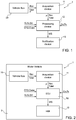
- the innovative method for estimating the wear of the tread of a pneumatic tyre is performed by a system shown in Figure 1 comprising an acquisition device 11 that is installed on board a motor vehicle equipped with two or more wheels, each equipped with a pneumatic tyre, and that is coupled to a vehicle bus 20 (based, for example, upon a standard Controller Area Network (CAN) bus) of said motor vehicle.
- the system 1 also comprises a processing device 12 that is connected, in wired or wireless mode, to the acquisition device 11.
- the acquisition device 11 is configured to acquire from the vehicle bus 20 signals that are indicative of the number of revolutions Rev of said two or more wheels. Furthermore, the acquisition device 11 is configured to supply at the output quantities that are indicative of the number of revolutions Rev of said two or more wheels.
- the acquisition device 11 is also configured to acquire from the vehicle bus 20 signals linked to the driving of the motor vehicle.
- the acquisition device 11 is configured to acquire from the vehicle bus 20 information in relation to the position of the vehicle (by means of the GPS signal).
- the acquisition device 11 is configured to acquire signals from the vehicle bus 20 in relation to the inflation pressure P of the pneumatic tyre (as measured by a system monitoring the pressure of the pneumatic tyres). Furthermore, the acquisition device 11 is configured to supply at the output quantities that are indicative of the inflation pressure P of the pneumatic tyre.
- the processing device 12 is implemented by means of a cloud type computing system that is wirelessly remotely connected to the acquisition device 11 (for example, by means of one or more technologies for mobile communications, such as GSM, GPRS, UMTS).
- a cloud type computing system that is wirelessly remotely connected to the acquisition device 11 (for example, by means of one or more technologies for mobile communications, such as GSM, GPRS, UMTS).
- the processing device 12 is implemented by means of an Electronic Control Unit - ECU (automotive use) 12 installed on board the motor vehicle 2.
- the electronic control unit may conveniently be a unit specifically dedicated to estimating the wear of the tread of pneumatic tyres, or else and preferably, it may be a unit dedicated to various tasks that also include estimating the wear of the tread of a pneumatic tyre.
- the following example describes the method for calculating a quantity WS that is indicative of the state of wear of the tread of the pneumatic tyre.
- the quantity WS is expressed as a percentage and represents the remaining thickness of the tread in relation to the thickness of the tread from new.
- the quantity WS is in fact determined in such a way that the higher the value of the quantity WS, the less the tread of the pneumatic tyre is consumed, and vice versa (the lower the value of the quantity WS, the more the tread of the pneumatic tyre is consumed).
- the quantity WS is equal to 100%, this signifies that the pneumatic tyre is substantially new and that the tread is not worn, whilst, on the contrary, when the quantity WS is equal to 0%, this signifies that the pneumatic tyre is substantially smooth, with the tread being completely worn.
- the distance TD to be traveled during the test step of the pneumatic tyre is greater than 1 km.
- the distance TD to be traveled during the test step of the pneumatic tyre is between 3 and 5 km. It was experimentally verified that a distance TD to be traveled during the test step of the pneumatic tyre of between 3 and 5 km makes it possible to significantly reduce the effects of the braking system and of the differences in driving conditions.
- the quantity WS which is indicative of the state of wear of the tread of the pneumatic tyre, is influenced by several variables, including, in particular, the inflation pressure of the pneumatic tyre (when different than the nominal inflation pressure). Furthermore, the quantity WS, which is indicative of the state of wear of the tread of the pneumatic tyre, is influenced by the braking action and by the speed of the motor vehicle.
- the inflation pressure of the pneumatic tyre affects the value of the circumference C of the tread.
- the value of the circumference C of the tread from new, when the tread is not worn, is therefore calculated in such a way as to take into account the effects of the inflation pressure.
- the braking action of the vehicle can reduce the actual number of revolutions Rev of the pneumatic tyre that are necessary in order to travel the distance TD to be traveled during the test step of the pneumatic tyre; for example, in the case wherein pure rolling of the pneumatic tyre is absent during braking (but, rather, the pneumatic tyre is dragged during braking), the actual number of revolutions Rev of the pneumatic tyre is reduced.
- the test step wherein the quantity WS, which is indicative of the state of wear of the tread of the pneumatic tyre, is only performed on straight sections wherein the braking system of the vehicle fitted with the pneumatic tyre is not operated (on motorways for example.)
- the quantity WS which is indicative of the state of wear of the tread of the pneumatic tyre, is corrected by means of a factor K 1 , which is indicative of the braking action of the vehicle during the test step.
- the speed of the vehicle could reduce the actual number of revolutions Rev of the pneumatic tyre that are necessary in order to travel the distance TD during the test step of the pneumatic tyre.
- the test step wherein the quantity WS, which is indicative of the state of wear of the tread of the pneumatic tyre, is only performed when the speed of the vehicle is maintained below a limiting value (for example, in the case of a truck, the limiting value is equal to 70 km/h).
- the limiting value is determined during a preliminary step and is substantially variable as a function of the type of motor vehicle.
- the quantity WS which is indicative of the state of wear of the tread of the pneumatic tyre, is corrected by means of a factor K 2 , which is indicative of the braking action of the vehicle during the test step.
- the factor K 2 is variable as a function of the ratio, or the difference, between the average speed of the vehicle over the distance TD traveled during the test step and the speed limiting value.
- the information relating to the distance traveled during the test step of the pneumatic tyre until the distance TD is reached is retrieved by means of the GPS signal of the vehicle.
- the system furthermore includes a notification device 13 that is configured to inform a user associated with said motor vehicle (for example, a driver and/or an owner of the same) of the detected wear, i.e., of the remaining thickness of the tread (expressed by means of the quantity WS).
- the notification device 13 is configured to inform a user in the case wherein the quantity WS is less than or equal to a safety value SV (equal, for example, to 60%).
- the notification device 13 is implemented by means of an electronic communication device 13 (such as a smartphone, a tablet, a laptop, a desktop computer, a smart TV, a smartwatch, etc.) of the user 3 of the motor vehicle 2, and that is remotely connected to the cloud type computing system 12 by means of one or more wired and/or wireless networks.
- an electronic communication device 13 such as a smartphone, a tablet, a laptop, a desktop computer, a smart TV, a smartwatch, etc.
- the notification device 13 is implemented by means of a Human-Machine Interface - HMI 13, which is provided on board the motor vehicle 2 and by means of which the ECU 12 can inform the driver of the motor vehicle by means of a graphical and/or audible warning produced by the HMI 13 (which, therefore, may conveniently comprise a screen and/or a graphical/acoustic signal).
- a Human-Machine Interface - HMI 13 which is provided on board the motor vehicle 2 and by means of which the ECU 12 can inform the driver of the motor vehicle by means of a graphical and/or audible warning produced by the HMI 13 (which, therefore, may conveniently comprise a screen and/or a graphical/acoustic signal).
- the innovative method for estimating the wear of the tread of a pneumatic tyre makes it possible to simultaneously and independently calculate the quantity WS that is indicative of the state of wear of the tread of each pneumatic tyre that is fitted to the vehicle.
- the acquisition device 11 may be conveniently configured such as to acquire signals and, therefore, provide at the output quantities that are indicative of the number of revolutions Rev of each wheel of the motor vehicle;
- the processing device 12 may conveniently be programmed to calculate the quantity WS for each wheel of the motor vehicle;
- the notification device 13 may be conveniently configured to signal to the user which pneumatic tyre is excessively worn.
Abstract
Description
- The present invention relates to a method and to a system for estimating the wear of the tread of a pneumatic tyre.
- As is known, when the tread of a pneumatic tyre wears, the performance of the same pneumatic tyre changes (degrades) considerably. Consequently, in order to improve the safety of a vehicle, it is of fundamental importance to be able to reliably detect the state of wear of a pneumatic tyre.
- The known methods for detecting the state of wear of a pneumatic tyre involve the use of an estimation model based upon a plurality of parameters. In particular, such methods utilize information relating to the operating state of the vehicle whereupon said pneumatic tyre is mounted (such as, for example, the load or else the acceleration) and environmental information (such as, for example, the conditions of the road surface traversed and the atmospheric conditions).
- These methods are not, however, easily implementable insofar as they involve a high computational burden.
- The patent application
GB2531746A - The aim of the present invention is to provide a method for estimating the wear of the tread of a pneumatic tyre that is both free from the disadvantages of the state of the art and that is, in particular, easy and inexpensive to implement.
- A further aim of the present invention is to provide a system for estimating the wear of the tread of a pneumatic tyre that is both free from the disadvantages of the state of the art and that is, in particular, easy and inexpensive to implement.
- According to the present invention a method and a system for estimating the wear of the tread of a pneumatic tyre are provided, according to that which is set forth in the attached claims.
- The present invention will now be described with reference to the attached drawings, which show an exemplary, non-limiting embodiment, wherein:
-
Figure 1 schematically illustrates a first embodiment of a system that implements the method for estimating the wear of the tread of a pneumatic tyre, which is the object of the present invention; -
Figure 2 schematically illustrates a first variant of the system inFigure 1 ; and -
Figure 3 schematically illustrates a second variant of the system inFigure 1 . - Based upon the results of performed tests, the applicant has designed and developed an innovative methodology, described in the discussion that follows, for estimating the wear of the tread of a pneumatic tyre.
- In particular, as the tread wears down, the diameter, and consequently the circumference, of a pneumatic tyre is progressively reduced. Therefore, for the same distance to be traveled, a greater number of revolutions will be necessary for a worn pneumatic tyre as compared to a new pneumatic tyre.
- The applicant has thereby experimentally verified that the difference in the number of revolutions in order to travel a certain distance during a test step, between a new pneumatic tyre and a worn pneumatic tyre, is proportional to the state of wear of the tread of the pneumatic tyre.
- The innovative method for estimating the wear of the tread of a pneumatic tyre is performed by a system shown in
Figure 1 comprising anacquisition device 11 that is installed on board a motor vehicle equipped with two or more wheels, each equipped with a pneumatic tyre, and that is coupled to a vehicle bus 20 (based, for example, upon a standard Controller Area Network (CAN) bus) of said motor vehicle. Thesystem 1 also comprises aprocessing device 12 that is connected, in wired or wireless mode, to theacquisition device 11. - The
acquisition device 11 is configured to acquire from thevehicle bus 20 signals that are indicative of the number of revolutions Rev of said two or more wheels. Furthermore, theacquisition device 11 is configured to supply at the output quantities that are indicative of the number of revolutions Rev of said two or more wheels. - The
acquisition device 11 is also configured to acquire from thevehicle bus 20 signals linked to the driving of the motor vehicle. In particular, theacquisition device 11 is configured to acquire from thevehicle bus 20 information in relation to the position of the vehicle (by means of the GPS signal). - Finally, the
acquisition device 11 is configured to acquire signals from thevehicle bus 20 in relation to the inflation pressure P of the pneumatic tyre (as measured by a system monitoring the pressure of the pneumatic tyres). Furthermore, theacquisition device 11 is configured to supply at the output quantities that are indicative of the inflation pressure P of the pneumatic tyre. - According to a first variant of the system shown in
Figure 3 , theprocessing device 12 is implemented by means of a cloud type computing system that is wirelessly remotely connected to the acquisition device 11 (for example, by means of one or more technologies for mobile communications, such as GSM, GPRS, UMTS). - In contrast, in a second variant of the system shown in
Figure 2 , theprocessing device 12 is implemented by means of an Electronic Control Unit - ECU (automotive use) 12 installed on board themotor vehicle 2. The electronic control unit may conveniently be a unit specifically dedicated to estimating the wear of the tread of pneumatic tyres, or else and preferably, it may be a unit dedicated to various tasks that also include estimating the wear of the tread of a pneumatic tyre. - The following example describes the method for calculating a quantity WS that is indicative of the state of wear of the tread of the pneumatic tyre. In particular, the quantity WS, which is indicative of the state of wear of the tread of the pneumatic tyre, is expressed using the following formula:
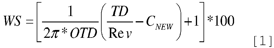
- WS
- quantity that is indicative of the state of wear of the tread of the pneumatic tyre;
- OTD
- thickness of the tread from new (when the tread is not worn);
- TD
- distance traveled by the pneumatic tyre during the test step;
- Rev
- actual number of revolutions of the pneumatic tyre that are required in order to travel the distance TD;
- CNEW
- initial circumference of the tread, when the pneumatic tyre is not worn and under nominal inflation pressure conditions.
- As is evident, the quantity WS is expressed as a percentage and represents the remaining thickness of the tread in relation to the thickness of the tread from new. The quantity WS is in fact determined in such a way that the higher the value of the quantity WS, the less the tread of the pneumatic tyre is consumed, and vice versa (the lower the value of the quantity WS, the more the tread of the pneumatic tyre is consumed). When the quantity WS is equal to 100%, this signifies that the pneumatic tyre is substantially new and that the tread is not worn, whilst, on the contrary, when the quantity WS is equal to 0%, this signifies that the pneumatic tyre is substantially smooth, with the tread being completely worn.
- As already highlighted, the formula [1] is applicable in the case wherein the pneumatic tyre is under conditions of nominal inflation pressure.
- In all other cases (with different inflation pressures than the nominal inflation pressure), however, the quantity WS, which is indicative of the state of wear of the tread of the pneumatic tyre, can be expressed using the following generic formula:

- WS
- quantity that is indicative of the state of wear of the tread of the pneumatic tyre;
- OTD
- thickness of the tread from new (when the tread is not worn);
- TD
- distance traveled by the pneumatic tyre during the test step;
- Rev
- actual number of revolutions of the pneumatic tyre that are required in order to travel the distance TD;
- C
- circumference of the tread from new (when the tread is not worn); variable as a function of the inflation pressure of pneumatic tyre.
- The distance TD to be traveled during the test step of the pneumatic tyre is greater than 1 km. Preferably, the distance TD to be traveled during the test step of the pneumatic tyre is between 3 and 5 km. It was experimentally verified that a distance TD to be traveled during the test step of the pneumatic tyre of between 3 and 5 km makes it possible to significantly reduce the effects of the braking system and of the differences in driving conditions.
- The applicant has also verified experimentally that the quantity WS, which is indicative of the state of wear of the tread of the pneumatic tyre, is influenced by several variables, including, in particular, the inflation pressure of the pneumatic tyre (when different than the nominal inflation pressure). Furthermore, the quantity WS, which is indicative of the state of wear of the tread of the pneumatic tyre, is influenced by the braking action and by the speed of the motor vehicle.
- In particular, the inflation pressure of the pneumatic tyre affects the value of the circumference C of the tread.
- The value of the circumference C of the tread from new, when the tread is not worn, is therefore calculated in such a way as to take into account the effects of the inflation pressure.
- In particular, the value of the circumference C of the tread from new is calculated using the following formula:

- C
- circumference of the tread from new, when the tread is not worn;
- C0
- circumference of the tread when the pneumatic tyre is deflated;
- K
- coefficient of correlation; and
- P
- relative inflation pressure (i.e., measured assuming as a reference the atmospheric pressure of the earth) of the pneumatic tyre (measured by means of a system for monitoring the pressure of pneumatic tyres).
- In turn, the correlation coefficient K is calculated using the following formula:

- CNEW
- circumference of the tread from new, when the pneumatic tyre is not worn and under nominal inflation pressure conditions.
- C0
- circumference of the tread when the pneumatic tyre is deflated;
- K
- coefficient of correlation; and
- PN
- relative inflation pressure (i.e., measured assuming as a reference the atmospheric pressure of the earth) of the pneumatic tyre.
- Furthermore, under certain conditions, the braking action of the vehicle can reduce the actual number of revolutions Rev of the pneumatic tyre that are necessary in order to travel the distance TD to be traveled during the test step of the pneumatic tyre; for example, in the case wherein pure rolling of the pneumatic tyre is absent during braking (but, rather, the pneumatic tyre is dragged during braking), the actual number of revolutions Rev of the pneumatic tyre is reduced.
- In order to take into account any effects of the speed of the vehicle, according to a first variant, the test step, wherein the quantity WS, which is indicative of the state of wear of the tread of the pneumatic tyre, is only performed on straight sections wherein the braking system of the vehicle fitted with the pneumatic tyre is not operated (on motorways for example.)
- According to a further variant, the quantity WS, which is indicative of the state of wear of the tread of the pneumatic tyre, is corrected by means of a factor K1, which is indicative of the braking action of the vehicle during the test step.
- Furthermore, the speed of the vehicle could reduce the actual number of revolutions Rev of the pneumatic tyre that are necessary in order to travel the distance TD during the test step of the pneumatic tyre.
- In order to take into account any effects of the speed of the vehicle, according to a first variant, the test step wherein the quantity WS, which is indicative of the state of wear of the tread of the pneumatic tyre, is only performed when the speed of the vehicle is maintained below a limiting value (for example, in the case of a truck, the limiting value is equal to 70 km/h). The limiting value is determined during a preliminary step and is substantially variable as a function of the type of motor vehicle.
- According to a further variant, the quantity WS, which is indicative of the state of wear of the tread of the pneumatic tyre, is corrected by means of a factor K2, which is indicative of the braking action of the vehicle during the test step. Preferably, the factor K2 is variable as a function of the ratio, or the difference, between the average speed of the vehicle over the distance TD traveled during the test step and the speed limiting value.
- With regard to the quantities used in the formulas [1] to [4] given above, it appears evident that the initial thickness OTD of the tread (when the tread is not worn) and the initial circumference CNEW of the tread (when the tread is not worn and under conditions of nominal inflation pressure) are supplied by the manufacturer of the pneumatic tyre and stored within the
processing device 12. Similarly, also the information regarding the circumference Co of the tread when the pneumatic tyre is deflated and the nominal inflation pressure PN of the pneumatic tyre are provided by the manufacturer of the pneumatic tyre and stored within theprocessing device 12. - The information relating to the distance traveled during the test step of the pneumatic tyre until the distance TD is reached is retrieved by means of the GPS signal of the vehicle.
- Referring again to
Figure 1 , the system furthermore includes anotification device 13 that is configured to inform a user associated with said motor vehicle (for example, a driver and/or an owner of the same) of the detected wear, i.e., of the remaining thickness of the tread (expressed by means of the quantity WS). In particular, thenotification device 13 is configured to inform a user in the case wherein the quantity WS is less than or equal to a safety value SV (equal, for example, to 60%). - According to the variant shown in
Figure 3 , thenotification device 13 is implemented by means of an electronic communication device 13 (such as a smartphone, a tablet, a laptop, a desktop computer, a smart TV, a smartwatch, etc.) of theuser 3 of themotor vehicle 2, and that is remotely connected to the cloudtype computing system 12 by means of one or more wired and/or wireless networks. - In contrast, according to the variant illustrated in
Figure 2 , thenotification device 13 is implemented by means of a Human-Machine Interface -HMI 13, which is provided on board themotor vehicle 2 and by means of which theECU 12 can inform the driver of the motor vehicle by means of a graphical and/or audible warning produced by the HMI 13 (which, therefore, may conveniently comprise a screen and/or a graphical/acoustic signal). - From the foregoing, it is also important to highlight that the innovative method for estimating the wear of the tread of a pneumatic tyre, as described heretofore, makes it possible to simultaneously and independently calculate the quantity WS that is indicative of the state of wear of the tread of each pneumatic tyre that is fitted to the vehicle. In fact, the
acquisition device 11 may be conveniently configured such as to acquire signals and, therefore, provide at the output quantities that are indicative of the number of revolutions Rev of each wheel of the motor vehicle; theprocessing device 12 may conveniently be programmed to calculate the quantity WS for each wheel of the motor vehicle; and thenotification device 13 may be conveniently configured to signal to the user which pneumatic tyre is excessively worn.
Claims (12)
- A method for estimating the wear of the tread of a pneumatic tyre that provides for calculating, during a test step, a quantity (WS) that is indicative of the remaining thickness of the tread in relation to the thickness of the tread from new using the formula:
 WS quantity that is indicative of the state of wear of the tread of the pneumatic tyre;OTD thickness of the tread from new (when the tread is not worn);TD distance traveled by the pneumatic tyre during the test step;Rev current number of revolutions of the pneumatic tyre that are required in order to travel said distance (TD) ;C circumference of the tread from new (when the tread is not worn); variable as a function of the inflation pressure (P) of pneumatic tyre;wherein, when the inflation pressure (P) of the pneumatic tyre is different than the nominal inflation pressure (PN), the circumference (C) of the tread from new is calculated using the formula:
 C circumference of the tread from new (when the tread is not worn) when the inflation pressure (P) of the pneumatic tyre is different than the nominal inflation pressure (PN);Co circumference of the tread when the pneumatic tyre is deflated;K coefficient of correlation; andP relative inflation pressure of the pneumatic tyre.
 - Method according to claim 1, wherein the coefficient of correlation (K) is calculated using the formula:
 CNEW circumference of the tread from new (when the pneumatic tyre is not worn) and under nominal inflation pressure (PN) conditions.C0 circumference of the tread when the pneumatic tyre is deflated;K coefficient of correlation; andPN relative nominal inflation pressure of the pneumatic tyre.
 - Method according to any one of the preceding claims wherein the distance (TD) to be traveled during the test step is greater than 1 km; preferably, the distance (TD) to be traveled during the test step is between 3 and 5 km.
- Method according to any one of the preceding claims, wherein the test step is only performed on straight sections wherein the braking system of the vehicle fitted with the pneumatic tyre is not operated.
- Method according to any one of the preceding claims and comprising the further steps of:determining a speed limiting value of the vehicle fitted with the pneumatic tyre; andperforming the test step only when the speed of the vehicle remains below the limiting value.
- Method according to any one of the preceding claims and comprising the further step of correcting the quantity (WS), which is indicative of the state of wear of the tread of the pneumatic tyre, by means of a second factor (K2) that is indicative of the speed of the of the vehicle fitted with the pneumatic tyre during the test step.
- Method according to claim 8 and comprising the further steps of
determining a speed limiting value of the vehicle fitted with the pneumatic tyre; and
calculate the second factor (K2) as a function of the ratio or the difference between the average speed of the vehicle over the distance (TD) traveled during the test step and said limiting value. - Method according to any one of the preceding claims and comprising the further step of informing a user in the case wherein the quantity (WS), which is indicative of the state of wear of the tread, is less than or equal to a safety value (SV).
- System (1) for estimating the wear of the tread of a pneumatic tyre in implementing the method according to any one of the preceding claims.
- System (1) according to claim 9 and comprising an acquisition device and a processing device (12); wherein the acquisition device (11) is:• installed on board a motor vehicle (2) provided with two or more wheels fitted with pneumatic tyres;• coupled to a vehicle bus (20) of the motor vehicle; and• configured towherein the processing device (12) is:- acquire, from the vehicle bus (20), signals that are indicative of the number of revolutions (Rev) of a wheel of said motor vehicle and information relating to the position of the vehicle; and- provide at the output quantities that are indicative of the number of revolutions (Rev) of the wheel of said motor vehicle and information relating to the position of the vehicle; and• configured to receive, from the acquisition device (11), quantities that are indicative of the number of revolutions (Rev) of the wheel of said motor vehicle and information relating to the position of the vehicle; and• programmed to- process the quantities relating to the number of revolutions (Rev) of the wheel of said motor vehicle and the information relating to the position of the vehicle; and- calculate, based upon the number of revolutions (Rev) of the wheel of said motor vehicle, the information relating to the position of the vehicle and the inflation pressure of the pneumatic tyre, a quantity (WS) that is indicative of the state of wear of the tread of the pneumatic tyre.
- System according to claim 10, wherein the processing device (12) is a cloud-type computing system that is remotely wirelessly connected to the acquisition device (11).
- System according to claim 10, wherein the processing device (12) is an electronic control unit installed on board the motor vehicle (2).
Applications Claiming Priority (1)
| Application Number | Priority Date | Filing Date | Title |
|---|---|---|---|
| IT102019000009555A IT201900009555A1 (en) | 2019-06-20 | 2019-06-20 | METHOD AND SYSTEM TO ESTIMATE THE WEAR OF A TIRE TREAD |
Publications (2)
| Publication Number | Publication Date |
|---|---|
| EP3753754A1 true EP3753754A1 (en) | 2020-12-23 |
| EP3753754B1 EP3753754B1 (en) | 2022-11-02 |
Family
ID=68582098
Family Applications (1)
| Application Number | Title | Priority Date | Filing Date |
|---|---|---|---|
| EP20180175.0A Active EP3753754B1 (en) | 2019-06-20 | 2020-06-16 | Method and system for estimating the wear of a tyre tread |
Country Status (2)
| Country | Link |
|---|---|
| EP (1) | EP3753754B1 (en) |
| IT (1) | IT201900009555A1 (en) |
Cited By (1)
| Publication number | Priority date | Publication date | Assignee | Title |
|---|---|---|---|---|
| EP4086088A1 (en) * | 2021-05-07 | 2022-11-09 | Continental Reifen Deutschland GmbH | Method and device for monitoring the tread depth of at least one vehicle tyre |
Citations (3)
| Publication number | Priority date | Publication date | Assignee | Title |
|---|---|---|---|---|
| EP2123487A1 (en) * | 2006-12-13 | 2009-11-25 | Kabushiki Kaisha Bridgestone | Device for estimating tire wear amount and vehicle mounted with device for estimating tire wear amount |
| GB2531746A (en) | 2014-10-28 | 2016-05-04 | Pre-Chasm Res Ltd | Tyre tread monitoring |
| US9610810B1 (en) * | 2015-10-21 | 2017-04-04 | The Goodyear Tire & Rubber Company | Method of tire state estimation through wheel speed signal feature extraction |
-
2019
- 2019-06-20 IT IT102019000009555A patent/IT201900009555A1/en unknown
-
2020
- 2020-06-16 EP EP20180175.0A patent/EP3753754B1/en active Active
Patent Citations (3)
| Publication number | Priority date | Publication date | Assignee | Title |
|---|---|---|---|---|
| EP2123487A1 (en) * | 2006-12-13 | 2009-11-25 | Kabushiki Kaisha Bridgestone | Device for estimating tire wear amount and vehicle mounted with device for estimating tire wear amount |
| GB2531746A (en) | 2014-10-28 | 2016-05-04 | Pre-Chasm Res Ltd | Tyre tread monitoring |
| US9610810B1 (en) * | 2015-10-21 | 2017-04-04 | The Goodyear Tire & Rubber Company | Method of tire state estimation through wheel speed signal feature extraction |
Cited By (1)
| Publication number | Priority date | Publication date | Assignee | Title |
|---|---|---|---|---|
| EP4086088A1 (en) * | 2021-05-07 | 2022-11-09 | Continental Reifen Deutschland GmbH | Method and device for monitoring the tread depth of at least one vehicle tyre |
Also Published As
| Publication number | Publication date |
|---|---|
| EP3753754B1 (en) | 2022-11-02 |
| IT201900009555A1 (en) | 2020-12-20 |
Similar Documents
| Publication | Publication Date | Title |
|---|---|---|
| CN101346247B (en) | Method and system for assisting a driver when parking or manoeuvring a motor vehicle | |
| US11054238B2 (en) | Method, system, and computer-readable medium for detecting wheel tread depth | |
| US8096174B2 (en) | Vehicle load weight detecting apparatus | |
| US10391823B2 (en) | Method and system for determining a pressure deviation between a setpoint tire pressure and an actual tire pressure for a tire of a vehicle as well as for determining a wheel load | |
| CN112292271B (en) | Tread wear monitoring method, system, electronic control unit, and storage medium | |
| US10352827B2 (en) | Tire contact state estimation method | |
| US7187273B2 (en) | System for determining a change in vehicle tire pressure | |
| CN112533775B (en) | Tread wear monitoring system and method | |
| US11912073B1 (en) | System and method for determining tire wear and defects | |
| JP3095956B2 (en) | Method for detecting reduced pressure tires in vehicles | |
| EP3501924A1 (en) | Wheel load estimation device | |
| EP3753754B1 (en) | Method and system for estimating the wear of a tyre tread | |
| JP5126048B2 (en) | Tire pressure monitoring device | |
| EP3856539B1 (en) | Tire damage detection system and method | |
| JP2003276627A (en) | Vehicle control device | |
| JP4028842B2 (en) | Tire pressure drop detection method and apparatus, and tire decompression determination program | |
| EP3642058B1 (en) | Wheel monitoring in a vehicle | |
| JP2011131845A (en) | Method, device and program for detecting drop of internal pressure of tire | |
| JP4536089B2 (en) | Tire pressure drop detection method and apparatus, and tire decompression determination program | |
| CN117715771A (en) | System and method for estimating in real time the rolling resistance of a tyre | |
| JP2006010401A (en) | Fuel consumption display apparatus | |
| JP2005153608A (en) | Method and device for detecting lowering of tire air pressure and tire pressure reduction determining program |
Legal Events
| Date | Code | Title | Description |
|---|---|---|---|
| PUAI | Public reference made under article 153(3) epc to a published international application that has entered the european phase |
Free format text: ORIGINAL CODE: 0009012 |
|
| STAA | Information on the status of an ep patent application or granted ep patent |
Free format text: STATUS: THE APPLICATION HAS BEEN PUBLISHED |
|
| AK | Designated contracting states |
Kind code of ref document: A1 Designated state(s): AL AT BE BG CH CY CZ DE DK EE ES FI FR GB GR HR HU IE IS IT LI LT LU LV MC MK MT NL NO PL PT RO RS SE SI SK SM TR |
|
| AX | Request for extension of the european patent |
Extension state: BA ME |
|
| STAA | Information on the status of an ep patent application or granted ep patent |
Free format text: STATUS: REQUEST FOR EXAMINATION WAS MADE |
|
| 17P | Request for examination filed |
Effective date: 20210909 |
|
| RBV | Designated contracting states (corrected) |
Designated state(s): AL AT BE BG CH CY CZ DE DK EE ES FI FR GB GR HR HU IE IS IT LI LT LU LV MC MK MT NL NO PL PT RO RS SE SI SK SM TR |
|
| GRAP | Despatch of communication of intention to grant a patent |
Free format text: ORIGINAL CODE: EPIDOSNIGR1 |
|
| STAA | Information on the status of an ep patent application or granted ep patent |
Free format text: STATUS: GRANT OF PATENT IS INTENDED |
|
| GRAJ | Information related to disapproval of communication of intention to grant by the applicant or resumption of examination proceedings by the epo deleted |
Free format text: ORIGINAL CODE: EPIDOSDIGR1 |
|
| STAA | Information on the status of an ep patent application or granted ep patent |
Free format text: STATUS: REQUEST FOR EXAMINATION WAS MADE |
|
| INTG | Intention to grant announced |
Effective date: 20220125 |
|
| GRAP | Despatch of communication of intention to grant a patent |
Free format text: ORIGINAL CODE: EPIDOSNIGR1 |
|
| STAA | Information on the status of an ep patent application or granted ep patent |
Free format text: STATUS: GRANT OF PATENT IS INTENDED |
|
| INTC | Intention to grant announced (deleted) | ||
| INTG | Intention to grant announced |
Effective date: 20220318 |
|
| GRAS | Grant fee paid |
Free format text: ORIGINAL CODE: EPIDOSNIGR3 |
|
| GRAA | (expected) grant |
Free format text: ORIGINAL CODE: 0009210 |
|
| STAA | Information on the status of an ep patent application or granted ep patent |
Free format text: STATUS: THE PATENT HAS BEEN GRANTED |
|
| AK | Designated contracting states |
Kind code of ref document: B1 Designated state(s): AL AT BE BG CH CY CZ DE DK EE ES FI FR GB GR HR HU IE IS IT LI LT LU LV MC MK MT NL NO PL PT RO RS SE SI SK SM TR |
|
| REG | Reference to a national code |
Ref country code: GB Ref legal event code: FG4D |
|
| REG | Reference to a national code |
Ref country code: CH Ref legal event code: EP Ref country code: AT Ref legal event code: REF Ref document number: 1528510 Country of ref document: AT Kind code of ref document: T Effective date: 20221115 |
|
| REG | Reference to a national code |
Ref country code: DE Ref legal event code: R096 Ref document number: 602020005986 Country of ref document: DE |
|
| REG | Reference to a national code |
Ref country code: IE Ref legal event code: FG4D |
|
| REG | Reference to a national code |
Ref country code: LT Ref legal event code: MG9D |
|
| REG | Reference to a national code |
Ref country code: NL Ref legal event code: MP Effective date: 20221102 |
|
| REG | Reference to a national code |
Ref country code: AT Ref legal event code: MK05 Ref document number: 1528510 Country of ref document: AT Kind code of ref document: T Effective date: 20221102 |
|
| RAP4 | Party data changed (patent owner data changed or rights of a patent transferred) |
Owner name: BRIDGESTONE EUROPE NV/SA |
|
| PG25 | Lapsed in a contracting state [announced via postgrant information from national office to epo] |
Ref country code: SE Free format text: LAPSE BECAUSE OF FAILURE TO SUBMIT A TRANSLATION OF THE DESCRIPTION OR TO PAY THE FEE WITHIN THE PRESCRIBED TIME-LIMIT Effective date: 20221102 Ref country code: PT Free format text: LAPSE BECAUSE OF FAILURE TO SUBMIT A TRANSLATION OF THE DESCRIPTION OR TO PAY THE FEE WITHIN THE PRESCRIBED TIME-LIMIT Effective date: 20230302 Ref country code: NO Free format text: LAPSE BECAUSE OF FAILURE TO SUBMIT A TRANSLATION OF THE DESCRIPTION OR TO PAY THE FEE WITHIN THE PRESCRIBED TIME-LIMIT Effective date: 20230202 Ref country code: LT Free format text: LAPSE BECAUSE OF FAILURE TO SUBMIT A TRANSLATION OF THE DESCRIPTION OR TO PAY THE FEE WITHIN THE PRESCRIBED TIME-LIMIT Effective date: 20221102 Ref country code: FI Free format text: LAPSE BECAUSE OF FAILURE TO SUBMIT A TRANSLATION OF THE DESCRIPTION OR TO PAY THE FEE WITHIN THE PRESCRIBED TIME-LIMIT Effective date: 20221102 Ref country code: ES Free format text: LAPSE BECAUSE OF FAILURE TO SUBMIT A TRANSLATION OF THE DESCRIPTION OR TO PAY THE FEE WITHIN THE PRESCRIBED TIME-LIMIT Effective date: 20221102 Ref country code: AT Free format text: LAPSE BECAUSE OF FAILURE TO SUBMIT A TRANSLATION OF THE DESCRIPTION OR TO PAY THE FEE WITHIN THE PRESCRIBED TIME-LIMIT Effective date: 20221102 |
|
| PG25 | Lapsed in a contracting state [announced via postgrant information from national office to epo] |
Ref country code: RS Free format text: LAPSE BECAUSE OF FAILURE TO SUBMIT A TRANSLATION OF THE DESCRIPTION OR TO PAY THE FEE WITHIN THE PRESCRIBED TIME-LIMIT Effective date: 20221102 Ref country code: PL Free format text: LAPSE BECAUSE OF FAILURE TO SUBMIT A TRANSLATION OF THE DESCRIPTION OR TO PAY THE FEE WITHIN THE PRESCRIBED TIME-LIMIT Effective date: 20221102 Ref country code: LV Free format text: LAPSE BECAUSE OF FAILURE TO SUBMIT A TRANSLATION OF THE DESCRIPTION OR TO PAY THE FEE WITHIN THE PRESCRIBED TIME-LIMIT Effective date: 20221102 Ref country code: IS Free format text: LAPSE BECAUSE OF FAILURE TO SUBMIT A TRANSLATION OF THE DESCRIPTION OR TO PAY THE FEE WITHIN THE PRESCRIBED TIME-LIMIT Effective date: 20230302 Ref country code: HR Free format text: LAPSE BECAUSE OF FAILURE TO SUBMIT A TRANSLATION OF THE DESCRIPTION OR TO PAY THE FEE WITHIN THE PRESCRIBED TIME-LIMIT Effective date: 20221102 Ref country code: GR Free format text: LAPSE BECAUSE OF FAILURE TO SUBMIT A TRANSLATION OF THE DESCRIPTION OR TO PAY THE FEE WITHIN THE PRESCRIBED TIME-LIMIT Effective date: 20230203 |
|
| P01 | Opt-out of the competence of the unified patent court (upc) registered |
Effective date: 20230511 |
|
| PG25 | Lapsed in a contracting state [announced via postgrant information from national office to epo] |
Ref country code: NL Free format text: LAPSE BECAUSE OF FAILURE TO SUBMIT A TRANSLATION OF THE DESCRIPTION OR TO PAY THE FEE WITHIN THE PRESCRIBED TIME-LIMIT Effective date: 20221102 |
|
| PG25 | Lapsed in a contracting state [announced via postgrant information from national office to epo] |
Ref country code: SM Free format text: LAPSE BECAUSE OF FAILURE TO SUBMIT A TRANSLATION OF THE DESCRIPTION OR TO PAY THE FEE WITHIN THE PRESCRIBED TIME-LIMIT Effective date: 20221102 Ref country code: RO Free format text: LAPSE BECAUSE OF FAILURE TO SUBMIT A TRANSLATION OF THE DESCRIPTION OR TO PAY THE FEE WITHIN THE PRESCRIBED TIME-LIMIT Effective date: 20221102 Ref country code: EE Free format text: LAPSE BECAUSE OF FAILURE TO SUBMIT A TRANSLATION OF THE DESCRIPTION OR TO PAY THE FEE WITHIN THE PRESCRIBED TIME-LIMIT Effective date: 20221102 Ref country code: DK Free format text: LAPSE BECAUSE OF FAILURE TO SUBMIT A TRANSLATION OF THE DESCRIPTION OR TO PAY THE FEE WITHIN THE PRESCRIBED TIME-LIMIT Effective date: 20221102 Ref country code: CZ Free format text: LAPSE BECAUSE OF FAILURE TO SUBMIT A TRANSLATION OF THE DESCRIPTION OR TO PAY THE FEE WITHIN THE PRESCRIBED TIME-LIMIT Effective date: 20221102 |
|
| PGFP | Annual fee paid to national office [announced via postgrant information from national office to epo] |
Ref country code: FR Payment date: 20230523 Year of fee payment: 4 Ref country code: DE Payment date: 20230523 Year of fee payment: 4 |
|
| REG | Reference to a national code |
Ref country code: DE Ref legal event code: R097 Ref document number: 602020005986 Country of ref document: DE |
|
| PG25 | Lapsed in a contracting state [announced via postgrant information from national office to epo] |
Ref country code: SK Free format text: LAPSE BECAUSE OF FAILURE TO SUBMIT A TRANSLATION OF THE DESCRIPTION OR TO PAY THE FEE WITHIN THE PRESCRIBED TIME-LIMIT Effective date: 20221102 Ref country code: AL Free format text: LAPSE BECAUSE OF FAILURE TO SUBMIT A TRANSLATION OF THE DESCRIPTION OR TO PAY THE FEE WITHIN THE PRESCRIBED TIME-LIMIT Effective date: 20221102 |
|
| PLBE | No opposition filed within time limit |
Free format text: ORIGINAL CODE: 0009261 |
|
| STAA | Information on the status of an ep patent application or granted ep patent |
Free format text: STATUS: NO OPPOSITION FILED WITHIN TIME LIMIT |
|
| 26N | No opposition filed |
Effective date: 20230803 |
|
| PG25 | Lapsed in a contracting state [announced via postgrant information from national office to epo] |
Ref country code: SI Free format text: LAPSE BECAUSE OF FAILURE TO SUBMIT A TRANSLATION OF THE DESCRIPTION OR TO PAY THE FEE WITHIN THE PRESCRIBED TIME-LIMIT Effective date: 20221102 |
|
| PG25 | Lapsed in a contracting state [announced via postgrant information from national office to epo] |
Ref country code: MC Free format text: LAPSE BECAUSE OF FAILURE TO SUBMIT A TRANSLATION OF THE DESCRIPTION OR TO PAY THE FEE WITHIN THE PRESCRIBED TIME-LIMIT Effective date: 20221102 |
|
| PG25 | Lapsed in a contracting state [announced via postgrant information from national office to epo] |
Ref country code: MC Free format text: LAPSE BECAUSE OF FAILURE TO SUBMIT A TRANSLATION OF THE DESCRIPTION OR TO PAY THE FEE WITHIN THE PRESCRIBED TIME-LIMIT Effective date: 20221102 |
|
| REG | Reference to a national code |
Ref country code: CH Ref legal event code: PL |
|
| REG | Reference to a national code |
Ref country code: BE Ref legal event code: MM Effective date: 20230630 |
|
| PG25 | Lapsed in a contracting state [announced via postgrant information from national office to epo] |
Ref country code: LU Free format text: LAPSE BECAUSE OF NON-PAYMENT OF DUE FEES Effective date: 20230616 |
|
| REG | Reference to a national code |
Ref country code: IE Ref legal event code: MM4A |
|
| PG25 | Lapsed in a contracting state [announced via postgrant information from national office to epo] |
Ref country code: LU Free format text: LAPSE BECAUSE OF NON-PAYMENT OF DUE FEES Effective date: 20230616 |
|
| PG25 | Lapsed in a contracting state [announced via postgrant information from national office to epo] |
Ref country code: IE Free format text: LAPSE BECAUSE OF NON-PAYMENT OF DUE FEES Effective date: 20230616 |