EP3753747B1 - Verpackungsanordnung zum verpacken von postsendungen unterschiedlicher grösse - Google Patents
Verpackungsanordnung zum verpacken von postsendungen unterschiedlicher grösse Download PDFInfo
- Publication number
- EP3753747B1 EP3753747B1 EP20180448.1A EP20180448A EP3753747B1 EP 3753747 B1 EP3753747 B1 EP 3753747B1 EP 20180448 A EP20180448 A EP 20180448A EP 3753747 B1 EP3753747 B1 EP 3753747B1
- Authority
- EP
- European Patent Office
- Prior art keywords
- assembly
- product
- transverse
- conveyor
- Prior art date
- Legal status (The legal status is an assumption and is not a legal conclusion. Google has not performed a legal analysis and makes no representation as to the accuracy of the status listed.)
- Active
Links
Images





Classifications
-
- B—PERFORMING OPERATIONS; TRANSPORTING
- B65—CONVEYING; PACKING; STORING; HANDLING THIN OR FILAMENTARY MATERIAL
- B65B—MACHINES, APPARATUS OR DEVICES FOR, OR METHODS OF, PACKAGING ARTICLES OR MATERIALS; UNPACKING
- B65B9/00—Enclosing successive articles, or quantities of material, e.g. liquids or semiliquids, in flat, folded, or tubular webs of flexible sheet material; Subdividing filled flexible tubes to form packages
- B65B9/06—Enclosing successive articles, or quantities of material, in a longitudinally-folded web, or in a web folded into a tube about the articles or quantities of material placed upon it
- B65B9/08—Enclosing successive articles, or quantities of material, in a longitudinally-folded web, or in a web folded into a tube about the articles or quantities of material placed upon it in a web folded and sealed transversely to form pockets which are subsequently filled and then closed by sealing
- B65B9/087—Enclosing successive articles, or quantities of material, in a longitudinally-folded web, or in a web folded into a tube about the articles or quantities of material placed upon it in a web folded and sealed transversely to form pockets which are subsequently filled and then closed by sealing the web advancing continuously
-
- B—PERFORMING OPERATIONS; TRANSPORTING
- B65—CONVEYING; PACKING; STORING; HANDLING THIN OR FILAMENTARY MATERIAL
- B65B—MACHINES, APPARATUS OR DEVICES FOR, OR METHODS OF, PACKAGING ARTICLES OR MATERIALS; UNPACKING
- B65B11/00—Wrapping, e.g. partially or wholly enclosing, articles or quantities of material, in strips, sheets or blanks, of flexible material
- B65B11/06—Wrapping articles, or quantities of material, by conveying wrapper and contents in common defined paths
- B65B11/08—Wrapping articles, or quantities of material, by conveying wrapper and contents in common defined paths in a single straight path
- B65B11/16—Wrapping articles, or quantities of material, by conveying wrapper and contents in common defined paths in a single straight path to fold the wrappers in channel form about contents and then to close the ends of the channel by folding and finally the mouth of the channel by folding or twisting
-
- B—PERFORMING OPERATIONS; TRANSPORTING
- B65—CONVEYING; PACKING; STORING; HANDLING THIN OR FILAMENTARY MATERIAL
- B65B—MACHINES, APPARATUS OR DEVICES FOR, OR METHODS OF, PACKAGING ARTICLES OR MATERIALS; UNPACKING
- B65B25/00—Packaging other articles presenting special problems
- B65B25/14—Packaging paper or like sheets, envelopes, or newspapers, in flat, folded, or rolled form
-
- B—PERFORMING OPERATIONS; TRANSPORTING
- B65—CONVEYING; PACKING; STORING; HANDLING THIN OR FILAMENTARY MATERIAL
- B65B—MACHINES, APPARATUS OR DEVICES FOR, OR METHODS OF, PACKAGING ARTICLES OR MATERIALS; UNPACKING
- B65B35/00—Supplying, feeding, arranging or orientating articles to be packaged
- B65B35/30—Arranging and feeding articles in groups
- B65B35/44—Arranging and feeding articles in groups by endless belts or chains
-
- B—PERFORMING OPERATIONS; TRANSPORTING
- B65—CONVEYING; PACKING; STORING; HANDLING THIN OR FILAMENTARY MATERIAL
- B65B—MACHINES, APPARATUS OR DEVICES FOR, OR METHODS OF, PACKAGING ARTICLES OR MATERIALS; UNPACKING
- B65B35/00—Supplying, feeding, arranging or orientating articles to be packaged
- B65B35/56—Orientating, i.e. changing the attitude of, articles, e.g. of non-uniform cross-section
-
- B—PERFORMING OPERATIONS; TRANSPORTING
- B65—CONVEYING; PACKING; STORING; HANDLING THIN OR FILAMENTARY MATERIAL
- B65B—MACHINES, APPARATUS OR DEVICES FOR, OR METHODS OF, PACKAGING ARTICLES OR MATERIALS; UNPACKING
- B65B51/00—Devices for, or methods of, sealing or securing package folds or closures; Devices for gathering or twisting wrappers, or necks of bags
- B65B51/10—Applying or generating heat or pressure or combinations thereof
- B65B51/26—Devices specially adapted for producing transverse or longitudinal seams in webs or tubes
-
- B—PERFORMING OPERATIONS; TRANSPORTING
- B65—CONVEYING; PACKING; STORING; HANDLING THIN OR FILAMENTARY MATERIAL
- B65B—MACHINES, APPARATUS OR DEVICES FOR, OR METHODS OF, PACKAGING ARTICLES OR MATERIALS; UNPACKING
- B65B57/00—Automatic control, checking, warning, or safety devices
-
- B—PERFORMING OPERATIONS; TRANSPORTING
- B65—CONVEYING; PACKING; STORING; HANDLING THIN OR FILAMENTARY MATERIAL
- B65B—MACHINES, APPARATUS OR DEVICES FOR, OR METHODS OF, PACKAGING ARTICLES OR MATERIALS; UNPACKING
- B65B59/00—Arrangements to enable machines to handle articles of different sizes, to produce packages of different sizes, to vary the contents of packages, to handle different types of packaging material, or to give access for cleaning or maintenance purposes
- B65B59/02—Arrangements to enable adjustments to be made while the machine is running
-
- B—PERFORMING OPERATIONS; TRANSPORTING
- B65—CONVEYING; PACKING; STORING; HANDLING THIN OR FILAMENTARY MATERIAL
- B65B—MACHINES, APPARATUS OR DEVICES FOR, OR METHODS OF, PACKAGING ARTICLES OR MATERIALS; UNPACKING
- B65B61/00—Auxiliary devices, not otherwise provided for, for operating on sheets, blanks, webs, binding material, containers or packages
- B65B61/04—Auxiliary devices, not otherwise provided for, for operating on sheets, blanks, webs, binding material, containers or packages for severing webs, or for separating joined packages
- B65B61/06—Auxiliary devices, not otherwise provided for, for operating on sheets, blanks, webs, binding material, containers or packages for severing webs, or for separating joined packages by cutting
-
- B—PERFORMING OPERATIONS; TRANSPORTING
- B65—CONVEYING; PACKING; STORING; HANDLING THIN OR FILAMENTARY MATERIAL
- B65B—MACHINES, APPARATUS OR DEVICES FOR, OR METHODS OF, PACKAGING ARTICLES OR MATERIALS; UNPACKING
- B65B9/00—Enclosing successive articles, or quantities of material, e.g. liquids or semiliquids, in flat, folded, or tubular webs of flexible sheet material; Subdividing filled flexible tubes to form packages
- B65B9/06—Enclosing successive articles, or quantities of material, in a longitudinally-folded web, or in a web folded into a tube about the articles or quantities of material placed upon it
-
- B—PERFORMING OPERATIONS; TRANSPORTING
- B65—CONVEYING; PACKING; STORING; HANDLING THIN OR FILAMENTARY MATERIAL
- B65B—MACHINES, APPARATUS OR DEVICES FOR, OR METHODS OF, PACKAGING ARTICLES OR MATERIALS; UNPACKING
- B65B2210/00—Specific aspects of the packaging machine
- B65B2210/04—Customised on demand packaging by determining a specific characteristic, e.g. shape or height, of articles or material to be packaged and selecting, creating or adapting a packaging accordingly, e.g. making a carton starting from web material
Definitions
- the invention relates to a continuously flow wrap packaging assembly for wrapping mail items of differing sizes and each including at least one mail component or a stack of mail components.
- a mail item may comprise a different selection of mail components compared to a subsequent mail item.
- EP0870678B1 discloses an approach for taking varying heights of mail items into account.
- An approach for taking varying heights of mail products into account, as is disclosed in EP0870678B1 may still result in wraps being oversized in at least the transverse direction, especially in the case of varying widths of subsequent mail items.
- This aspect is complicated by the fact that conventionally, the longitudinal seal is continuously applied to the stream of mail items, upstream of the cross sealing assembly, before separating the mail products in the cross sealing assembly.
- US5299410 discloses a packaging method and mechanism to be used for forming a shrink wrap package which will shrink wrap stacks of paper of different size. US'410 does not disclose that the web is supplied continuously and in view of the construction it is clear that the web of US'410 is supplied intermittently and the sealing is performed when the web and the stack enclosed by the web is stationary. For example, column 2, lines 63-66 describe that the heat seal knives 10, 11, 12 are vertically moveable. This implies that the web is stationary when the sealing takes place because otherwise, the heat seal knives 10, 11, 12 should additionally be able to move in the transport direction of the web during sealing. In view thereof, US'410 is of a completely different type of machine than the continuous flow wrap machine of EP'678 and of the present invention. US'410 discloses two embodiments.
- the first embodiment shown in Fig. 1 does not include a fold wrap station which is configured to continuously fold the web around the mail items thereby creating a folded web so as to have a single side fold which is positioned on a first side, wherein the side fold extends in the transport direction.
- a fold wrap station which is configured to continuously fold the web around the mail items thereby creating a folded web so as to have a single side fold which is positioned on a first side, wherein the side fold extends in the transport direction.
- an upper foil web and a lower foil web are supplied above and below a stack of mail items.
- the transverse position of two longitudinal seal knives may be varied dependent on information stored in a computer to accommodate the size of the stack. It is disclosed that the actual size of the stack may be sensed by sensing means before it reaches the seal module.
- the sealer module of the second embodiment has means for spreading the two laminates 8, 9 apart and to subsequently cover a stack of mail items. Subsequently, the thus covered stack then moves to the sealing area which seals the edges in a manner similar to the embodiment shown in the first embodiment.
- US'410 does not disclose a cross sealing assembly which is configured for cross sealing the folded web between the subsequently placed mail items and for separating from the folded web to form an intermediate product.
- the longitudinal seal knives disclosed in US'410 do not seal an intermediate product which is already separated from the continuous web but, instead, seal simultaneously with the transverse sealing knife 10 around the stack on laminate parts which are not yet separated from the web which has been supplied to the sealing station.
- the structures of EP'678 and US'410 and the type of operation, continuously flow wrap versus intermittent, are completely different from each other.
- EP'678 the width of the package is fixed. The width is not determined by a position of a longitudinal seal but by the distance between two longitudinal fold lines.
- US'410 the width of the package to be formed is variable but is not determined by a longitudinal fold line but by the distance between two longitudinal seals.
- a mail product is a packaged mail item and a mail item may comprise one mail component or a stack of a plurality of mail components.
- Mail components of subsequent mail items may be of different dimensions. Also, relative positions and orientations of corresponding mail components may vary between subsequent mail items, e.g. due to instabilities induced by stacking of mail components.
- Such variation of dimensions between mail items needs to be taken into account in order to avoid faults in the wrapping process.
- the seals need to be positioned appropriately with respect to the mail items in order to ensure that all mail products are fully wrapped and have appropriate seals.
- the seals are therefore positioned to accommodate for the largest possible dimensions in a batch of mail items.
- many mail products will have oversized wraps, which is undesired and may even be prohibited by postal services responsible for delivering the mail product to its recipient.
- the present invention provides an assembly according to claim 1.
- the invention provides a packaging assembly for wrapping mail items of differing sizes and each including at least one mail component or a stack of mail components.
- the packaging assembly comprises:
- the packaging assembly is characterized in that the flow wrap station is configured to create said folded web so as to have a single side fold which is positioned on a first side of the subsequently placed mail items, wherein the side fold extends in the transport direction.
- the packaging assembly further comprises a measuring assembly for determining a transverse position of a second side of the mail item which is opposite the first side.
- the longitudinal sealing assembly has an infeed end which is positioned downstream of the cross sealing assembly.
- the longitudinal sealing assembly is configured for creating a mail product by applying a longitudinal seal in each intermediate mail product at the second side of the mail item.
- the longitudinal sealing assembly comprises a positioning assembly for controlling a transverse position of the longitudinal seal for each intermediate mail product, wherein the transverse position of the longitudinal seal is determined by the transverse position of the second side of the mail item.
- the present invention further provides a method according to claim 16.
- the method is for wrapping mail items of differing sizes and each including at least one mail component or a stack of mail components.
- the method comprises:
- the invention thus advantageously provides a solution for wrapping mail items tightly, particularly mail items of varying widths, resulting in mail products having appropriately sized wraps in at least the transverse direction.
- the packaging assembly may further comprise an alignment assembly having an infeed end positioned upstream of the longitudinal sealing assembly, preferably upstream of the measuring assembly, and downstream of the cross sealing assembly, wherein the alignment assembly is configured to move the individual mail components of the mail item to cause alignment of edges of the individual mail components of the mail item along and adjacent to the side fold.
- the alignment assembly can thus advantageously minimize the width of the mail item, thus providing the possibility for subsequently forming a tighter wrap in the transverse direction.
- the alignment assembly may comprise a first tilting assembly configured to tilt the intermediate mail product around an axis of rotation from a first orientation to a second orientation, wherein the axis of rotation extends substantially in the transport direction, wherein the second orientation is a substantially less horizontal orientation compared to the first orientation, and wherein, in the second orientation, the gravity force exerted on the individual mail components has a force component which is directed towards the side fold.
- the alignment assembly may advantageously enable leveraging effects of gravity to move the individual mail components of the mail item to cause alignment of edges of the individual mail components of the mail item along and adjacent to the side fold.
- the first tilting assembly may comprise a dispatch timing assembly positioned at an infeed end of the first tilting assembly, configured to control the tilting of each intermediate mail product, wherein the dispatch timing assembly comprises a plurality of support surfaces connected to a rotatable shaft and extending radially outwardly from the shaft, wherein the shaft extends substantially in the transport direction.
- Each support surface of the dispatch timing assembly preferably comprises a transport conveyor for guiding each intermediate mail product in the transport direction.
- Such a dispatch timing assembly advantageously enables to prevent intermediate mail products from twisting during the tilting, wherein twisting can lead to tearing of the associated web part, among other possible faults.
- the alignment assembly may further comprise a back tilting assembly positioned downstream of the first tilting assembly.
- the back tilting assembly is configured to tilt the intermediate mail product around a second axis of rotation from the second orientation to a third orientation, wherein the second axis of rotation extends substantially in the transport direction.
- the third orientation is a substantially more horizontal orientation compared to the second orientation.
- the third orientation may correspond to an infeed orientation of the longitudinal sealing assembly, being a more suitable orientation for applying a longitudinal seal compared to the second orientation, while enabling that the previously realized alignment of edges of mail components be maintained.
- the longitudinal sealing assembly may comprise a heat seal head, in particular a seal swing head.
- Such a heat seal head advantageously provides means for applying the longitudinal seal and for creating a tightly wrapped mail product.
- the heat seal head may be connected to the positioning assembly to vary and control a transverse position of the heat seal head in dependence of the transverse position of the second side of the respective mail item.
- the longitudinal sealing assembly of this embodiment comprises: a longitudinal sealing conveyor for further transporting the intermediate mail product substantially in the transport direction; a transverse guide extending in a direction transverse to the transport direction; a carriage to which the longitudinal sealing conveyor and the heat seal head are connected for varying a transverse position thereof; and a transverse actuator for moving the carriage with the longitudinal sealing conveyor and the heat seal head along the transverse guide and for positioning these at a desired transverse position.
- such a longitudinal sealing assembly enables receiving intermediate mail products at controllably varying transverse positions on the longitudinal sealing conveyor, effectively compensating for variations of mail item widths between mail items of subsequent intermediate mail products.
- the positioning assembly may comprise an intermediate mail product transverse displacement assembly configured to move a respective intermediate mail product in a direction transverse to the transport direction.
- the intermediate mail product transverse displacement assembly of this embodiment is positioned upstream of the heat seal head which has a substantially fixed position.
- the intermediate mail product transverse displacement assembly may comprise: a guide, for example a rod or a roller, positioned along the transport direction at a transverse position substantially corresponding to a transverse position of the heat seal head, and forming a narrow passage for two end flaps of the associated web part, wherein the narrow passage is substantially small with respect to a thickness of the mail item; a second clamping assembly positioned at an opposite side of the guide from the mail item and configured to clamp the two end flaps; a push bar positioned in between the guide and the second clamping assembly and configured to push the two end flaps in between the guide and the second clamping assembly in an outward direction from the plane between the guide and the second clamping assembly so as to pull the two end flaps through the narrow passage thereby repositioning the mail item relative to the heat seal head.
- a guide for example a rod or a roller
- such a longitudinal sealing assembly effectively enables alignment of the second sides of the mail items to a substantially fixed transverse position, substantially corresponding to a transverse position of the heat seal head, while maintaining the previously obtained alignment of edges of mail components to the side fold of the associated web part.
- the intermediate mail product transverse displacement assembly may further comprise: the previously defined measuring assembly.
- the determining of the transverse position of the second side of the mail item comprises determining a displacement resistance, particularly an increased displacement resistance, of the push bar.
- the intermediate mail product transverse displacement assembly of this embodiment additionally comprises a displacement controller configured to reduce the displacement of the push bar, depending on the displacement resistance.
- the aspect of measuring a transverse position of the second side of the mail item is effectively combined with adjusting that transverse position to a substantially fixed transverse position.
- the collecting conveyor is provided with one or more alignment means configured for moving one or more of the individual mail components of the mail item transverse to the transport direction prior to wrapping in the flow wrap station, for example moving one individual mail component with respect to another individual mail component of the same mail item and/or moving one or more individual mail components, for example together, transverse to a transport path the collecting conveyor.
- alignment means can advantageously minimize the width of the mail item, thus providing the possibility for subsequently forming a tighter wrap in the transverse direction.
- the alignment means can provide an alternative or addition to the above-described alignment assembly.
- a preferred packaging assembly comprises both the alignment means and the alignment assembly. It has been found that such a preferred packaging assembly can provide particularly good wrapping of a wide variety of mail items.
- the alignment means may be realized in various ways.
- the alignment means may comprise one or more spring elements, for example leaf springs, which are arranged along the conveyor to bias mail items transverse to the transport direction upon contact with the spring elements.
- spring elements can advantageously cause a mail component to overlap more with an underlying mail component of the same mail item, thus enabling a tighter wrap.
- the alignment means may comprise one or more rollers arranged in a transport surface of the collecting conveyor, which rollers define a roller axis which extends relative to the transport direction at an angle of more than zero degrees and less than 90 degrees, for example an angle in the range of 60 to 75 degrees.
- rollers can advantageously bias a lowest mail component of a mail item to align with a side wall or the like of the collecting conveyor, in particular such that the mail item is thereby subsequently (more) aligned with the single side fold created in the flow wrap station.
- alignment means may alternatively or additionally be provided elsewhere, for example at the infeed end of the flow wrap station and/or at the at least one feeder.
- Fig. 1 shows a schematic overview of a packaging assembly 10 of an exemplary embodiment, the packaging assembly 10 having a transport direction 22 and comprising a mail item collecting assembly 16, a flow wrap station 26, a cross sealing assembly 40, an alignment assembly 66, a measuring assembly 48, a longitudinal sealing assembly 52 and a trimming assembly 152.
- assemblies are shown as being positioned downstream or upstream of other assemblies along the transport direction 22, in some embodiments, the assemblies may be positioned differently and assemblies may overlap along the transport direction 22. Also, while the transport direction 22 is shown as a straight line, it may be directed along a curved and/or cornered path in some embodiments.
- the mail item collecting assembly 16 includes at least one feeder 20 for dispatching individual mail components 14 to a collecting conveyor 18 having a downstream end 24.
- the flow wrap station 26 has an infeed end 30 which connects to the downstream end 24 of the collecting conveyor 18 and comprises a folding assembly 32.
- the longitudinal sealing assembly 52 may include a heat seal head 128, in particular a seal swing head.
- the trimming assembly 152 may be provided for removing, e.g. by means of suction, an excess web part 154 (see Fig. 3g ) from the mail product 56 and may include a suction pump 156 having a fluid inlet 158.
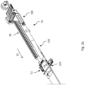
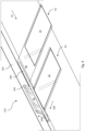
- Fig. 2a shows an isometric view of a downstream section of an exemplary packaging assembly 10 comprising a longitudinal sealing assembly 52, wherein a longitudinal seal 58 is applied in an intermediate mail product 42 and wherein a mail product 56 is downstream of the intermediate mail product 42, wherein the intermediate mail product 42 is in a third orientation 122.
- Fig. 2a further shows: a first tilting assembly 70 with a holding assembly 90 and a dispatch timing assembly 108; and a back tilting assembly 118.
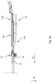
- Fig. 2b shows a side view corresponding to the isometric view of Fig. 2a , in which side view the downward direction of the gravitational force field is indicated by arrow 78.
- the first tilting assembly 70 comprises a tilted conveyor 82 configured for further transporting the intermediate mail product 42 substantially in the transport direction 22.
- a transverse slope 84 of the tilted conveyor 82 extends between an upper longitudinal side 86 of the tilted conveyor 82 and a lower longitudinal side 88 of the tilted conveyor 82.
- the first tilting assembly 70 additionally comprises a holding assembly 90.
- such a tilted conveyor 82 provides means for receiving and maintaining the intermediate mail product 42 in a tilted orientation while transporting the intermediate mail product 42 further in the transport direction 22.
- the holding assembly 90 comprises a first clamping assembly 92 positioned along and adjacent to the upper longitudinal side 86 of the tilted conveyor 82 and configured to clamp two end flaps 94 of the associated web part 46 of the intermediate mail product 42.
- such a holding assembly 90 provides means for holding the associated web part 46 at a controlled vertical position, e.g. a substantially constant vertical position, without directly inhibiting a downward movement of mail components 14 contained within the associated web part 46 thanks to gravity.
- the downward movement combined with the holding of the associated web part 46 may result in edges of mail components 14 becoming aligned to the side fold 36.
- the holding assembly 90 comprises a suction assembly 96 for holding the intermediate mail product 42 onto the tilted conveyor 82.
- the suction assembly 96 comprises a fluid inlet 98, a suction pump 100 having a fluid connection to the fluid inlet 98 and a fluid transmissive area of a conveyor belt of the tilted conveyor 82.
- the fluid inlet 98 is positioned directly below an intermediate mail product receiving area of the tilted conveyor 82.
- the tilted conveyor 82 is configured for passing the fluid transmissive area of the conveyor belt directly over the fluid inlet 98 and for creating a sub-atmospheric pressure between the fluid inlet 98 and the intermediate mail product 42 so as to suck the intermediate mail product 42 onto the conveyor belt.
- such a suction assembly 96 provides for holding the associated web part 46 tightly onto the tilted conveyor 82.
- an intermediate mail product 42 (comprising a mail item 12 and an associated web part 46) is received along a transport direction 22 in a first orientation 74.
- the second side of the intermediate mail product 42 is received in the holding assembly 90 while the respective first side is received on the dispatch timing assembly 108.
- the second side is dropped so that the intermediate mail product 42 is received, substantially without being twisted, on the first tilting assembly 70 in the second orientation 76.
- a downstream back tilting assembly 118 then brings the intermediate mail product 42 to a third orientation 122 as shown in Fig. 3g , in which orientation a longitudinal seal 58 is applied to it in the longitudinal sealing assembly 52, resulting in a mail product 56.
- an excess web part 154 is removed from the mail product 56 in a trimming assembly 152.
- Fig. 2c shows an examplary embodiment of the dispatch timing assembly 108 positioned at the infeed end 68 first tilting assembly 70.
- the dispatch timing assembly 108 comprising support surfaces 112 which are connected to a rotatable shaft 114 and extend radially outwardly from the shaft 114.
- the shaft 114 extends substantially in the transport direction 22.
- the dispatch timing assembly 108 is configured to control the tilting of each intermediate mail product 42.
- each support surface 112 comprises a transport conveyor.
- the intermediate mail product 42 is received at the infeed end 68, where its second side is clamped in the clamping assembly 92.
- the clamping assembly 92 may include, for example, two belts that are pressed against each other.
- the holding assembly 90 may further comprise a suction assembly 96 for further holding the intermediate mail product 42 onto the tilted conveyor 82 once it is received there.
- the fluid inlet 98 may connect to some or all of the receiving surface of the tilted conveyor 82, for instance.
- the transverse slope 84 of the tilted conveyor 82 preferably substantially corresponds to the second orientation 76.
- the method for wrapping mail items 12 comprises: providing a packaging assembly 10 according to the invention; receiving a side fold 36 of an intermediate mail product 42 on a first of the plurality of support surfaces 112 of the dispatch timing assembly 108; and releasing the side fold 36, after the receiving, by rotating the rotatable shaft 114 to move the first support surface 112 from a substantially horizontal position downwardly to a releasing position.
- Each support surface 112 is thus cycled through subsequent positions.
- the surfaces 112 may be rotated by 90 degrees around the shaft 114 each time after receiving a subsequent intermediate mail product 42.
- the back tilting assembly 118 comprises a back tilting conveyor 124 for further transporting the intermediate mail product 42 substantially in the transport direction 22.
- An infeed end 126 of the back tilting conveyor 124 is positioned downstream of an outfeed end 83 of the first tilting assembly 70.
- a transverse slope 113 of at least an outfeed end 115 of the back tilting conveyor 124 is small compared to the transverse slope 84 of the tilted conveyor 82.
- a transverse slope of the infeed end 126 may be substantially corresponding to a transverse slope 84 of the first tilting assembly 70.
- the back tilting conveyor 124 is thus advantageously configured to bring an intermediate mail product 42 from a second orientation 76 to a third, more horizontal orientation, wherein the transverse slope 113 of the outfeed end 115 preferably corresponds to the third orientation 122.
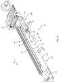
- Fig. 2d shows a second partial isometric view of the section shown in Figs. 2a-2b , showing an example of the longitudinal sealing assembly 52.
- the longitudinal sealing assembly 52 comprises an infeed end 54 and a longitudinal sealing conveyor 132.
- a transverse guide 133 is provided together with a carriage 135 to which the longitudinal sealing conveyor 132 and the heat seal head 128 are connected.
- a transverse actuator 134 is provided for moving the carriage 135 along the transverse guide 133.
- the combination of at least the guide 133 and the carriage 135 may form a positioning assembly 62 for controlling a transverse position of the longitudinal seal 58 for each intermediate mail product 42.
- the method for wrapping mail items 12 comprises: providing a packaging assembly 10 according to the invention; and creating a mail product 56 by applying the longitudinal seal 58 in an intermediate mail product 42 which is received on the longitudinal sealing conveyor 132 while moving the carriage 135 with the longitudinal sealing conveyor 132 and the heat seal head 128 along the transverse guide 133 for positioning these at a transverse position corresponding to a transverse position of a longitudinal seal 58 determined for an intermediate mail product 42 directly upstream of the longitudinal sealing conveyor 132.
- an intermediate mail product 42 is received in the third orientation 122 at an infeed end 54 of the longitudinal sealing assembly 52.
- the longitudinal sealing conveyor 132 and the heat seal head 128 are moved to an appropriate receiving transverse position using the transverse guide 133 and the carriage 135, so that e.g. the second side of the mail item 12 is received at a transverse position substantially corresponding to a transverse position of the heat seal head 128.
- a longitudinal seal 58 is then applied by the heat seal head 128 in the received intermediate mail product 42. While the longitudinal seal 58 is being applied, the heat seal head 128 and the longitudinal sealing conveyor 132 may already be moved to an appropriate transverse position for receiving a subsequent intermediate mail product 42 so as to minimize delays and improve throughput.
- the packaging assembly 10 may comprise a trimming assembly 152 configured to remove an excess web part 154 from the mail product 56, the excess web part 154 being a part or parts of the associated web part 46.
- the excess web part 154 is located at a side of the longitudinal seal 58 opposite to the mail item 12.
- the trimming assembly 152 forms part of or is located downstream of the longitudinal sealing assembly 52.
- such a trimming assembly 152 provides means for creating a mail product 56 that is free from excess web parts 154.
- the trimming assembly 152 includes a suction pump 156 having a fluid inlet 158, wherein the trimming assembly 152 is configured to create a sub-atmospheric pressure between the fluid inlet 158 and the excess web part 154 so as to suck the excess web part 154 away from the mail product 56.
- such a trimming assembly 152 enables that the excess web part 154 is effectively, efficiently and safely removed.
- the trimming assembly 152 may be configured to remove the excess web part 154 from the mail product 56 through clamping and/or pulling, e.g. using one or more belts, of the excess web part 154, in particular through pulling the excess web part 154 away from the mail product 56.
- the measuring assembly 48 may be realized in various ways, including the use of optical (e.g. camera) systems, among other known alternatives.
- the measuring assembly 48 may comprise a computer system having a user interface for manually entering a dimension (e.g. a cross width) of a mail component 14 that is being dispatched by a feeder 20, based on which the transverse position of the second side of the mail item 12 is determined in the computer system.
- a dimension e.g. a cross width
- the transverse position of the second side of the mail item 12 is preferably measured after the sides of the mail components 14 have been aligned in the alignment assembly 66.
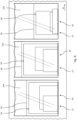
- Figs. 3a-3i show a set of three subsequent exemplary mail items, 12 wherein the different figures relate to different stages or aspects of processing according to an exemplary method and/or using an exemplary embodiment.
- Fig. 3a shows three subsequent mail items 12 being transported on a collecting conveyor 18 in a transport direction 22, wherein each mail item 12 includes mail components 14, which have generally different dimensions within and between mail items 12.
- each mail item 12 is composed of three mail components 14.
- the number of mail components 14 within a mail item 12 may vary between mail items 12 and may be lower or higher than three.
- the mail items 12 are advanced in the transport direction 22 by projections 15 that are connected to an endless chain 17 that is driven.
- Fig. 3b shows that a folded web 34 has been created around the mail items 12, wherein the folded web 34 has a side fold 36 extending in the transport direction 22 and positioned on a first side of the mail items 12.
- the web consists of a transparent foil.
- Fig. 3c shows cross seals 41 in the folded web 34 having been created between 41 the mail items 12.
- Fig. 3d shows that the folded web 34 has been separated into discrete intermediate mail products 42 comprising the mail items 12 and their associated web parts 46, wherein each web part 46 comprises two end flaps 94.
- applying the cross seal 41 and separating a downstream intermediate mail product 42 may be combined in a substantially single operation, e.g. using a seal head with an integrated cutting device or by cross sealing and simultaneously pulling a downstream product away from the upstream product.
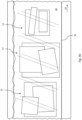
- Fig. 3e shows a top view of intermediate mail products 42 being tilted in a first tilting assembly 70 around an axis of rotation 72 from a first orientation 74 to a second orientation 76, preferably moving through an intermediate orientation 75.
- the axis of rotation 72 extends in the transport direction 22.
- the second orientation 76 is a substantially less horizontal orientation compared to the first orientation 74.
- the gravity force exerted on the individual mail components 14 has a force component 80 which is directed towards the side fold 36.
- the downward direction of the gravitational force field is directed into the surface of the drawing as indicated by arrow 78 in Fig 3e .
- Fig. 3f shows a side view corresponding to the top view of Fig. 3e .
- the downward direction of the gravitational force field is as indicated by arrow 78.
- sides of mail components 14 of the mail item 12 in the second orientation 76 are shown to be aligned along and adjacent to the side fold 36, whereas they were not so aligned before the tilting, as shown in e.g. Fig. 3d .
- sides of mail components 14 of the mail item 12 in the intermediate orientation 75 are in the process of becoming so aligned as the mail item 12 is being tilted from the first orientation 74 to the second orientation 76 and the gravity force component 80 directed towards the side fold 36 increases from substantially zero in the first orientation 74 to substantially nonzero in the second orientation 76.
- Figs. 3e-f show that one intermediate mail product 42 is in a second orientation 76 while a second upstream intermediate mail product 42 is in a first orientation 74. It will be appreciated that this is not meant as limiting the invention but merely to show subsequent orientations in a concise manner. Depending on further details of embodiments, such distances between intermediate mail products 42 may be larger or smaller.
- force components 80 can be thought of as acting on the centers of gravity of mail components 14, irrespective of the exact locations where arrows 80 are positioned in the drawings. Dimensions of arrows 80 are not meant to confer an exact size of the force components 80.
- Fig. 3g shows mail products 56 having been created by applying a longitudinal seal 58 in each intermediate mail product 42, wherein the transverse position of the longitudinal seal 58 is determined by the transverse position of the second side of the respective mail item 12.
- An excess web part 154 is shown for each mail product 56, wherein the excess web part 154 is located at a side of the longitudinal seal 58 opposite to the mail item 12.
- Fig. 3g the side folds 36 of the mail products 56 are shown to be aligned to each other. In some embodiments, however, the transverse positions of the longitudinal seals 58 may be aligned to each other at this stage, whereby the side folds 36 may not be aligned any longer.
- Fig. 3h shows the respective mail products 56 after their excess web parts 154 (not shown in Fig. 3h ) have been removed, resulting in mail products 56 of varying widths that are tightly wrapped in the transverse direction.
- determining the transverse position of the longitudinal seal 58 for each intermediate mail product 42 may comprise: receiving, for example through a user interface of the packaging assembly 10, a desired transverse offset 59 between the longitudinal seal 58 of the intermediate mail product 42 and the second side of the respective mail item 12; and determining the transverse position of the longitudinal seal 58 for the intermediate mail product 42 based on, in particular by summation of, the transverse position of the second side of the respective mail item 12 and the desired transverse offset 59.
- a tightness of the wrapping and/or a size of the mail product relative to the respective mail item can be adjusted e.g. according to a customer preference, wherein some customers may prefer a somewhat less tightly packaged mail product and/or a mail product having a particular offset or a particular minimal offset between the second side of the respective mail item and the longitudinal seal.
- Fig. 4 shows an isometric view of an exemplary intermediate mail product 42 transverse displacement assembly 170 configured to move a respective intermediate mail product 42 in a direction 168 transverse to the transport direction 22.
- the intermediate mail product transverse displacement assembly 170 is preferably positioned upstream of the heat seal head 128 which has a substantially fixed position.
- the intermediate mail product transverse displacement assembly 170 is shown to include a guide 160, for example a rod or a roller, positioned along the transport direction 22 at a transverse position substantially corresponding to a transverse position of the heat seal head 128, i.e. a transverse position substantially corresponding to a desired transverse position of the second side of the mail item 12.
- a guide 160 for example a rod or a roller
- the guide 160 is thus configured for restricting a passage for two end flaps 94 of the associated web part 46, wherein the passage is substantially narrow with respect to a thickness of the mail item 12.
- a second clamping assembly 162 configured to clamp the two end flaps 94, is preferably positioned at a side of the guide 160 opposite from the mail item 12.
- a push bar 164 is positioned in between the guide 160 and the second clamping assembly 162 and configured to push the two end flaps 94 in between the guide 160 and the second clamping assembly 162 in an outward direction 166 from the plane between the guide 160 and the second clamping assembly 162 so as to pull the two end flaps 94 through the passage thereby repositioning the mail item 12 relative to the heat seal head 128.
- the second side of the mail item 12 is pulled against the guide 160, wherein the transverse position of the guide 160 substantially corresponds to the transverse position of the downstream heat seal head 128.
- the push bar 164 may be controlled to ensure appropriate repositioning through appropriate outward displacement, in particular an appropriate end position of the push bar 164, for each intermediate mail product 42, in dependence of the transverse position of the second side of the mail item 12.
- the appropriate end position may be determined depending on an initial transverse position of the second side of the mail item 12 as determined by an upstream measurement assembly (not shown).
- the appropriate end position may be determined by measuring a displacement resistance of the push bar 164, wherein an increased displacement resistance is associated with the second side of the mail item 12 being pulled against the guide 160.
- detection of such an increased displacement resistance may be used to control, particularly limit, e.g. end, a further outward displacement of the push bar 164.
- the push bar 164 may be a first push bar of an array of push bars of the packaging assembly 10, wherein the array includes at least a second push bar (not shown) downstream of the first push bar, wherein the second push bar may be positioned in between the guide 160 and the second clamping assembly 162 and configured to push the two end flaps 94 in between the guide 160 and the second clamping assembly 162 in an outward direction 166 from the plane between the guide 160 and the second clamping assembly 162 so as to cause tension in the two end flaps 94 and/or elsewhere in the associated web part 46, in particular during application of the longitudinal seal 58, wherein the second push bar may form part of the longitudinal sealing assembly 52.
- Such tensioning can improve the quality and efficiency of the process of applying the longitudinal seal and the quality of the resulting longitudinal seal. While such tensioning may be achieved using a single push bar 164, the use of a second push bar can enable more efficient wrapping of mail items, in particular by enabling a reduction of a distance between mail items in the transport direction. For example, an upstream mail item may be processed at the first push bar while a downstream mail item is processed at the second push bar.
Landscapes
- Engineering & Computer Science (AREA)
- Mechanical Engineering (AREA)
- Basic Packing Technique (AREA)
- Packaging Of Special Articles (AREA)
Claims (19)
- Verpackungsanordnung (10) zum Umhüllen von Poststücken (12) unterschiedlicher Größe, die jeweils mindestens eine Postkomponente (14) oder einen Stapel von Postkomponenten (14) einschließen, die Verpackungsanordnung (10) umfassend:- eine Sammelanordnung (16) für Poststücke, die einen Sammelförderer (18) und mindestens einen Zuführer (20) zum Abgeben einzelner Postkomponenten (14) an den Sammelförderer (18) einschließt, um die Poststücke (12) zusammenzustellen, die anschließend in einer Transportrichtung (22) zu einem stromabwärtigen Ende (24) des Sammelförderers (18) transportiert werden;- eine Fließwickelstation (26), die zum Wickeln einer kontinuierlichen Materialbahn um die Poststücke (12) konfiguriert ist, wobei die Fließwickelstation (26) ein Zuführungsende (30) aufweist, das mit dem stromabwärtigen Ende (24) des Sammelförderers (18) verbunden ist, um anschließend die in der Sammelanordnung (16) zusammengestellten Poststücke (12) auf der kontinuierlichen Bahn zu platzieren, wobei die Fließwickelstation (26) eine Faltanordnung (32) umfasst, die zum kontinuierlichen Falten der Bahn um die Poststücke (12) konfiguriert ist, wodurch eine gefaltete Bahn (34) erzeugt wird;- eine Querversiegelungsanordnung (40), die stromabwärts der Faltanordnung (32) positioniert und konfiguriert ist, um die gefaltete Bahn (34) zwischen (41) den nachfolgend platzierten Poststücken (12) quer zu versiegeln und um von der gefalteten Bahn (34) ein Zwischenpostprodukt (42) zu trennen, das ein stromabwärts liegendes Poststück (12) der nachfolgend platzierten Poststücke (12) und einen zugehörigen Bahnteil (46) umfasst;- eine Längsversiegelungsanordnung (52) zum Erzeugen einer Längsversiegelung (58);dadurch gekennzeichnet, dassdie Fließwickelstation (26) konfiguriert ist, um die gefaltete Bahn (34) so zu erzeugen, dass sie eine einzelne Seitenfalte (36) aufweist, die auf einer ersten Seite der nachfolgend platzierten Poststücke (12) positioniert ist, wobei sich die Seitenfalte (36) in der Transportrichtung (22) erstreckt;wobei die Verpackungsanordnung (10) ferner umfasst:- eine Messanordnung (48) zum Bestimmen einer Querposition einer zweiten Seite des Poststücks (12), die der ersten Seite gegenüberliegt; undwobei die Längsversiegelungsanordnung (52) ein Zuführungsende (54) aufweist, das stromabwärts der Querversiegelungsanordnung (40) positioniert ist, wobei die Längsversiegelungsanordnung (52) konfiguriert ist, um ein Postprodukt (56) durch Aufbringen einer Längsversiegelung (58) in jedem Zwischenpostprodukt (42) an der zweiten Seite des Poststücks (12) zu erzeugen, wobei die Längsversiegelungsanordnung (52) eine Positionierungsanordnung (62) zum Steuern einer Querposition der Längsversiegelung (58) für jedes Zwischenpostprodukt (42) umfasst, wobei die Querposition der Längsversiegelung (58) durch die Querposition der zweiten Seite des Poststücks (12) bestimmt wird.
- Verpackungsanordnung (10) nach Anspruch 1, ferner umfassend:- eine Ausrichtungsanordnung (66) mit einem Zuführungsende, das stromaufwärts der Längsversiegelungsanordnung (52) und stromabwärts der Querversiegelungsanordnung (40) positioniert ist, wobei die Ausrichtungsanordnung (66) zum Bewegen der einzelnen Postkomponenten (14) des Poststücks (12) konfiguriert ist, um eine Ausrichtung der Kanten der einzelnen Postkomponenten (14) des Poststücks (12) entlang und angrenzend an die Seitenfalte (36) zu verursachen.
- Verpackungsanordnung (10) nach Anspruch 2, wobei das Zuführungsende der Ausrichtungsanordnung (66) stromaufwärts von der Messanordnung (48) angeordnet ist.
- Verpackungsanordnung (10) nach einem der Ansprüche 2 bis 3, wobei die Ausrichtungsanordnung (66) Folgendes umfasst:- eine erste Kippanordnung (70), die konfiguriert ist, um das Zwischenpostprodukt (42) um eine Drehachse (72) von einer ersten Ausrichtung (74) in eine zweite Ausrichtung (76) zu kippen, wobei sich die Drehachse (72) im Wesentlichen in der Transportrichtung (22) erstreckt, wobei die zweite Ausrichtung (76) eine im Vergleich zu der ersten Ausrichtung (74) wesentlich weniger horizontale Ausrichtung ist, und wobei in der zweiten Ausrichtung (76) die auf die einzelnen Postkomponenten (14) ausgeübte Schwerkraft eine Kraftkomponente (80) aufweist, die auf die Seitenfalte (36) gerichtet ist.
- Verpackungsanordnung (10) nach Anspruch 4, wobei die erste Kippanordnung (70) Folgendes umfasst:- einen Kippförderer (82), der konfiguriert ist, um das Zwischenpostprodukt (42) im Wesentlichen in der Transportrichtung (22) weiter zu transportieren, wobei sich eine Querneigung (84) des Kippförderers (82) zwischen einer oberen Längsseite (86) des Kippförderers (82) und einer unteren Längsseite (88) des Kippförderers (82) erstreckt; und- eine Halteanordnung (90).
- Verpackungsanordnung (10) nach Anspruch 5, wobei die Halteanordnung (90) Folgendes umfasst:- eine erste Klemmanordnung (92), die entlang und angrenzend an die obere Längsseite (86) des Kippförderers (82) positioniert und konfiguriert ist, um zwei Endlaschen (94) des zugehörigen Bahnteils (46) des Zwischenpostprodukts (42) zu klemmen.
- Verpackungsanordnung (10) nach einem der Ansprüche 4 bis 6, wobei die erste Kippanordnung (70) Folgendes umfasst:- eine Versandzeitgeberanordnung (108), die an einem Zuführungsende (68) der ersten Kippanordnung (70) positioniert und konfiguriert ist, um das Kippen jedes Zwischenpostprodukts (42) zu steuern, wobei die Versandzeitgeberanordnung (108) eine Vielzahl von Stützflächen (112) umfasst, die mit einer drehbaren Welle (114) verbunden sind und sich von der Welle (114) aus radial nach außen erstrecken, wobei sich die Welle (114) im Wesentlichen in der Transportrichtung (22) erstreckt.
- Verpackungsanordnung (10) nach Anspruch 7, wobei jede Stützfläche (112) der Versandzeitgeberanordnung (108) einen Transportförderer zum Führen jedes Zwischenpostprodukts (42) in der Transportrichtung (22) umfasst.
- Verpackungsanordnung (10) nach einem der Ansprüche 4 bis 8, wobei die Ausrichtungsanordnung (66) Folgendes umfasst:- eine Rückkippanordnung (118), die stromabwärts der ersten Kippanordnung (70) positioniert ist, wobei die Rückkippanordnung (118) konfiguriert ist, um das Zwischenpostprodukt (42) um eine zweite Drehachse (120) von der zweiten Ausrichtung (76) zu einer dritten Ausrichtung (122) zu kippen, wobei sich die zweite Drehachse (120) im Wesentlichen in der Transportrichtung (22) erstreckt, wobei die dritte Ausrichtung (122) eine im Vergleich zu der zweiten Ausrichtung (76) wesentlich horizontalere Ausrichtung ist.
- Verpackungsanordnung (10) nach Anspruch 9, wobei die Rückkippanordnung (118) Folgendes umfasst:- einen Rückkippförderer (124) zum weiteren Transportieren des Zwischenpostprodukts (42) im Wesentlichen in der Transportrichtung (22), wobei ein Zuführungsende (126) des Rückkippförderers (124) stromabwärts von einem Abführungsende (83) der ersten Kippanordnung (70) positioniert ist, wobei eine Querneigung (113) mindestens eines Abführungsendes (115) des Rückkippförderers (124) im Vergleich zu der Querneigung (84) des Kippförderers (82) klein ist.
- Verpackungsanordnung (10) nach einem der vorstehenden Ansprüche, wobei die Längsversiegelungsanordnung (52) Folgendes umfasst:- einen Heißsiegelkopf (128), insbesondere einen Siegelschwenkkopf, wobei der Heißsiegelkopf (128) mit der Positionierungsanordnung (62) verbunden ist, um eine Querposition des Heißsiegelkopfes (128) in Abhängigkeit von der Querposition der zweiten Seite des jeweiligen Poststücks (12) zu verändern und zu steuern,- einen Längsversiegelungsförderer (132) zum weiteren Transportieren des Zwischenpostprodukts (42) im Wesentlichen in der Transportrichtung (22);- eine Querführung (133), die sich in einer Richtung quer zu der Transportrichtung (22) erstreckt;- einen Wagen (135), mit dem der Längsversiegelungsförderer (132) und der Heißsiegelkopf (128) verbunden sind, um eine Querposition davon zu verändern;- einen Querstellantrieb (134) zum Bewegen des Wagens (135) mit dem Längsversiegelungsförderer (132) und dem Heißsiegelkopf (128) entlang der Querführung (133) und zum Positionieren dieser in einer gewünschten Querposition.
- Verpackungsanordnung (10) nach Anspruch 11, wobei die Positionierungsanordnung (62) Folgendes umfasst:- eine Zwischenpostprodukt-Querverschiebungsanordnung (170), die konfiguriert ist, um ein entsprechendes Zwischenpostprodukt (42) in einer Richtung (168) quer zu der Transportrichtung (22) zu bewegen, wobei die Zwischenpostprodukt-Querverschiebungsanordnung (170) stromaufwärts von dem Heißsiegelkopf (128) positioniert ist, der eine im Wesentlichen feste Position hat.
- Verpackungsanordnung (10) nach Anspruch 12, wobei die Zwischenpostprodukt-Querverschiebungsanordnung (170) Folgendes umfasst:- eine Führung (160), beispielsweise eine Stange oder eine Rolle, die entlang der Transportrichtung (22) in einer Querposition positioniert ist, die im Wesentlichen einer Querposition des Heißsiegelkopfes (128) entspricht, und die einen engen Durchgang für zwei Endlaschen (94) des zugehörigen Bahnteils (46) bildet, wobei der enge Durchgang in Bezug auf eine Dicke des Poststücks (12) im Wesentlichen klein ist;- eine zweite Klemmanordnung (162), die an einer dem Poststück (12) gegenüberliegenden Seite der Führung (160) positioniert und konfiguriert ist, um die beiden Endlaschen (94) zu klemmen;- eine Schubstange (164), die zwischen der Führung (160) und der zweiten Klemmanordnung (162) positioniert und konfiguriert ist, um die zwei Endlaschen (94) zwischen der Führung (160) und der zweiten Klemmanordnung (162) in einer Richtung (166) nach außen von der Ebene zwischen der Führung (160) und der zweiten Klemmanordnung (162) zu schieben, sodass die zwei Endlaschen (94) durch den engen Durchgang gezogen werden, wodurch das Poststück (12) relativ zu dem Heißsiegelkopf (128) neu positioniert wird.
- Verpackungsanordnung (10) nach Anspruch 13, wobei die Zwischenpostprodukt-Querverschiebungsanordnung (170) ferner Folgendes umfasst:- die Messanordnung (48), wobei das Bestimmen der Querposition der zweiten Seite des Poststücks (12) das Bestimmen eines Verschiebungswiderstands, insbesondere eines erhöhten Verschiebungswiderstands, der Schubstange (164) umfasst; und- eine Verschiebungssteuerung, die konfiguriert ist, um die Verschiebung der Schubstange (164) in Abhängigkeit von dem Verschiebungswiderstand zu reduzieren.
- Verpackungsanordnung (10) nach einem der vorstehenden Ansprüche, umfassend:- eine Schneidanordnung (152), die konfiguriert ist, um ein überschüssiges Bahnteil (154) von dem Postprodukt (56) zu entfernen, wobei das überschüssige Bahnteil (154) ein Teil oder Teile des zugehörigen Bahnteils (46) ist, wobei das überschüssige Bahnteil (154) an einer Seite der Längsversiegelung (58) gegenüber dem Poststück (12) angeordnet ist, wobei die Schneidanordnung (152) einen Teil der Längsversiegelungsanordnung (52) bildet oder stromabwärts davon angeordnet ist.
- Verfahren zum Umhüllen von Poststücken (12) unterschiedlicher Größe, die jeweils mindestens eine Postkomponente (14) oder einen Stapel von Postkomponenten (14) einschließen, das Verfahren umfassend:- Bereitstellen einer Verpackungsanordnung (10) nach einem der Ansprüche 1 bis 15;- Zusammenstellen von Poststücken (12) auf dem Sammelförderer (18) durch Empfangen von Postkomponenten (14) von dem mindestens einen Zuführer (20) und Transportieren der Poststücke (12) auf dem Sammelförderer (18) in einer Transportrichtung (22) zu einem stromabwärtigen Ende (24) des Sammelförderers (18);- Wickeln einer kontinuierlichen Materialbahn um die Poststücke (12) durch Zuführen einer kontinuierlichen Bahn zu dem Zuführungsende (30) der Fließwickelstation (26), anschließendes Platzieren der zusammengestellten Poststücke (12) auf der kontinuierlichen Bahn und kontinuierliches Falten der Bahn um die Poststücke (12), wodurch eine gefaltete Bahn (34) mit einer einzelnen Seitenfalte (36) erzeugt wird, die auf einer ersten Seite der anschließend platzierten Poststücke (12) positioniert ist, wobei sich die Seitenfalte (36) in der Transportrichtung (22) erstreckt;- Querversiegeln der gefalteten Bahn (34) zwischen (41) den nachfolgend platzierten Poststücken (12) und Trennen eines Zwischenpostprodukts (42) von der gefalteten Bahn (34), das ein stromabwärts liegendes Poststück (12) der nachfolgend platzierten Poststücke (12) und einen zugehörigen Bahnteil (46) umfasst;- Bestimmen einer Querposition einer zweiten Seite eines jeden Poststücks (12), wobei die zweite Seite der ersten Seite gegenüberliegt;- Bestimmen einer Querposition einer Längsversiegelung (58) für jedes Zwischenpostprodukt (42) basierend auf der Querposition der zweiten Seite des jeweiligen Poststücks (12); und- Erzeugen eines Postprodukts (56) durch Aufbringen der Längsversiegelung (58) in jedem Zwischenpostprodukt (42) an der für dieses Zwischenpostprodukt (42) bestimmten Querposition.
- Verfahren nach Anspruch 16, umfassend:- Bereitstellen einer Verpackungsanordnung (10) nach einem der Ansprüche 11 und 15; und- Erzeugen eines Postprodukts (56) durch Aufbringen der Längsversiegelung (58) in einem Zwischenpostprodukt (42), das auf dem Längsversiegelungsförderer (132) aufgenommen wird, während der Wagen (135) mit dem Längsversiegelungsförderer (132) und dem Heißsiegelkopf (128) entlang der Querführung (133) bewegt wird, um diese in einer Querposition zu positionieren, die einer Querposition einer Längsversiegelung (58) entspricht, die für ein Zwischenpostprodukt (42) direkt stromaufwärts des Längsversiegelungsförderers (132) bestimmt wurde.
- Verfahren nach Anspruch 16 oder 17, umfassend:- Bereitstellen einer Verpackungsanordnung (10) nach einem der Ansprüche 7 bis 15;- Aufnehmen einer Seitenfalte (36) eines Zwischenpostprodukts (42) auf einer ersten der Vielzahl von Stützflächen (112); und- Freigeben der Seitenfalte (36) nach der Aufnahme durch Drehen der drehbaren Welle (114), um die erste Stützfläche nach unten zu bewegen.
- Verfahren nach einem der Ansprüche 16 bis 18, wobei das Bestimmen der Querposition der Längsversiegelung (58) für jedes Zwischenpostprodukt (42) Folgendes umfasst:- Empfangen, beispielsweise über eine Benutzerschnittstelle der Verpackungsanordnung (10), eines gewünschten Querversatzes (59) zwischen der Längsversiegelung (58) des Zwischenpostprodukts (42) und der zweiten Seite des jeweiligen Poststücks (12); und- Bestimmen der Querposition der Längsversiegelung (58) für das Zwischenpostprodukt (42) basierend auf, insbesondere durch Summierung, der Querposition der zweiten Seite des jeweiligen Poststücks (12) und dem gewünschten Querversatz (59).
Applications Claiming Priority (1)
| Application Number | Priority Date | Filing Date | Title |
|---|---|---|---|
| NL2023321A NL2023321B1 (en) | 2019-06-17 | 2019-06-17 | A packaging assembly for wrapping mail items of differing sizes |
Publications (4)
| Publication Number | Publication Date |
|---|---|
| EP3753747A2 EP3753747A2 (de) | 2020-12-23 |
| EP3753747A3 EP3753747A3 (de) | 2021-04-28 |
| EP3753747B1 true EP3753747B1 (de) | 2024-12-04 |
| EP3753747C0 EP3753747C0 (de) | 2024-12-04 |
Family
ID=67352558
Family Applications (1)
| Application Number | Title | Priority Date | Filing Date |
|---|---|---|---|
| EP20180448.1A Active EP3753747B1 (de) | 2019-06-17 | 2020-06-17 | Verpackungsanordnung zum verpacken von postsendungen unterschiedlicher grösse |
Country Status (4)
| Country | Link |
|---|---|
| US (1) | US11401062B2 (de) |
| EP (1) | EP3753747B1 (de) |
| NL (1) | NL2023321B1 (de) |
| PL (1) | PL3753747T3 (de) |
Families Citing this family (1)
| Publication number | Priority date | Publication date | Assignee | Title |
|---|---|---|---|---|
| IT202000019420A1 (it) * | 2020-08-06 | 2022-02-06 | Tecno Pack S P A | Macchina confezionatrice orizzontale con gruppo taglia-cuci regolabile |
Citations (3)
| Publication number | Priority date | Publication date | Assignee | Title |
|---|---|---|---|---|
| US3339337A (en) * | 1964-10-08 | 1967-09-05 | Raymond I Rapp | Envelope, apparatus and method for making and filling envelopes |
| EP0686555A1 (de) * | 1994-06-06 | 1995-12-13 | Buhrs-Zaandam B.V. | Faltorgan für eine Verpackungsvorrichtung, Verpackungsvorrichtung mit einem solchen Faltorgan und Verfahren zu seiner Anwendung |
| EP0870678B1 (de) * | 1997-04-07 | 2002-01-23 | Buhrs-Zaandam B.V. | Vorrichtung zum Verpacken von Gegenständen unterschiedlicher Dicke |
Family Cites Families (9)
| Publication number | Priority date | Publication date | Assignee | Title |
|---|---|---|---|---|
| GB1255776A (en) * | 1968-02-17 | 1971-12-01 | Ind Developments Packaging Ltd | Improvements in or relating to wrapping apparatus |
| US3581461A (en) * | 1969-04-29 | 1971-06-01 | South Steel Corp | Packaging apparatus |
| US5417041A (en) * | 1991-11-12 | 1995-05-23 | Clamco Corporation | Horizontal wrapper with a side seal attachment |
| US5299410A (en) * | 1992-11-05 | 1994-04-05 | Gunther International, Ltd. | Packaging mechanism and method |
| JP2007008583A (ja) * | 2005-06-01 | 2007-01-18 | Ishida Co Ltd | 包装システム |
| ITFI20060152A1 (it) * | 2006-06-16 | 2007-12-17 | Kpl Packaging Spa | Macchina e metodo perli confezionamento di gruppi di prodotti |
| BRPI0817325A2 (pt) * | 2007-09-25 | 2015-03-24 | Ferag Ag | Aparelho para processar artigos planos, em particular, produtos impressos |
| US10160558B2 (en) * | 2011-05-13 | 2018-12-25 | Texwrap Packaging Systems Llc | High speed vertical film wrapping and sealing machine |
| US10967995B1 (en) * | 2018-03-13 | 2021-04-06 | Amazon Technologies, Inc. | Inflatable packaging materials, automated packaging systems, and related methods |
-
2019
- 2019-06-17 NL NL2023321A patent/NL2023321B1/en active
-
2020
- 2020-06-17 PL PL20180448.1T patent/PL3753747T3/pl unknown
- 2020-06-17 EP EP20180448.1A patent/EP3753747B1/de active Active
- 2020-06-17 US US16/903,877 patent/US11401062B2/en active Active
Patent Citations (4)
| Publication number | Priority date | Publication date | Assignee | Title |
|---|---|---|---|---|
| US3339337A (en) * | 1964-10-08 | 1967-09-05 | Raymond I Rapp | Envelope, apparatus and method for making and filling envelopes |
| EP0686555A1 (de) * | 1994-06-06 | 1995-12-13 | Buhrs-Zaandam B.V. | Faltorgan für eine Verpackungsvorrichtung, Verpackungsvorrichtung mit einem solchen Faltorgan und Verfahren zu seiner Anwendung |
| EP0686555B1 (de) * | 1994-06-06 | 1998-09-02 | Buhrs-Zaandam B.V. | Faltorgan für eine Verpackungsvorrichtung, Verpackungsvorrichtung mit einem solchen Faltorgan und Verfahren zu seiner Anwendung |
| EP0870678B1 (de) * | 1997-04-07 | 2002-01-23 | Buhrs-Zaandam B.V. | Vorrichtung zum Verpacken von Gegenständen unterschiedlicher Dicke |
Also Published As
| Publication number | Publication date |
|---|---|
| EP3753747A3 (de) | 2021-04-28 |
| US11401062B2 (en) | 2022-08-02 |
| PL3753747T3 (pl) | 2025-03-31 |
| NL2023321B1 (en) | 2021-01-25 |
| US20200391888A1 (en) | 2020-12-17 |
| EP3753747A2 (de) | 2020-12-23 |
| EP3753747C0 (de) | 2024-12-04 |
Similar Documents
| Publication | Publication Date | Title |
|---|---|---|
| US5603198A (en) | Process and apparatus for wrapping articles with stretchable film | |
| AU744393B2 (en) | Method and device for strapping individual objects or stacks of objects | |
| AU712087B2 (en) | Method and apparatus for automatically packaging a food or non food product | |
| EP2325087B1 (de) | Maschine zur aufeinanderfolgenden Umreifung von Bündeln | |
| US11401062B2 (en) | Packaging assembly for wrapping mail items of differing sizes | |
| CA2460913C (en) | Bundling assembly for strapping machine | |
| US7320206B2 (en) | Device for processing flat objects, especially for packing printed products | |
| CN111094134B (zh) | 包装系统和包装物体的方法 | |
| CN115043041A (zh) | 用于包装不同类型的物品的方法和设备 | |
| AU718825B2 (en) | Method and apparatus for placing cornerboards and wrapping a load | |
| JP5229659B2 (ja) | シート供給装置およびこれを用いたシート包装機 | |
| US10781006B2 (en) | Packaging machine for packaging with stretch film and optimized packaging method | |
| US5113639A (en) | Selective article wrapping | |
| WO2016178875A1 (en) | Apparatus and method of using an apparatus for controlling a film | |
| JP5271819B2 (ja) | 胴巻き包装機 | |
| WO2016142710A1 (en) | Packaging system | |
| EP1799553B1 (de) | Banderoliervorrichtung und diese verwendendes verfahren | |
| US20080209856A1 (en) | Work Piece Wrapping Apparatus | |
| JPS63152513A (ja) | 包装装置 | |
| JP2025081133A (ja) | 包装品の製造方法および包装装置 | |
| JP4141334B2 (ja) | シート体の加工装置 | |
| JPH08169413A (ja) | 梱包装置 | |
| EP3712095B1 (de) | Vorrichtung zum verleimen eines endes einer rolle | |
| JP2025081134A (ja) | 包装品の製造方法および包装装置 | |
| WO2024231482A1 (en) | Card dispensing apparatus |
Legal Events
| Date | Code | Title | Description |
|---|---|---|---|
| PUAI | Public reference made under article 153(3) epc to a published international application that has entered the european phase |
Free format text: ORIGINAL CODE: 0009012 |
|
| STAA | Information on the status of an ep patent application or granted ep patent |
Free format text: STATUS: THE APPLICATION HAS BEEN PUBLISHED |
|
| AK | Designated contracting states |
Kind code of ref document: A2 Designated state(s): AL AT BE BG CH CY CZ DE DK EE ES FI FR GB GR HR HU IE IS IT LI LT LU LV MC MK MT NL NO PL PT RO RS SE SI SK SM TR |
|
| AX | Request for extension of the european patent |
Extension state: BA ME |
|
| PUAL | Search report despatched |
Free format text: ORIGINAL CODE: 0009013 |
|
| AK | Designated contracting states |
Kind code of ref document: A3 Designated state(s): AL AT BE BG CH CY CZ DE DK EE ES FI FR GB GR HR HU IE IS IT LI LT LU LV MC MK MT NL NO PL PT RO RS SE SI SK SM TR |
|
| AX | Request for extension of the european patent |
Extension state: BA ME |
|
| RIC1 | Information provided on ipc code assigned before grant |
Ipc: B43M 3/00 20060101AFI20210323BHEP Ipc: B65B 9/00 20060101ALI20210323BHEP Ipc: B65B 9/06 20120101ALI20210323BHEP Ipc: B65B 25/14 20060101ALI20210323BHEP Ipc: B65B 35/32 20060101ALI20210323BHEP Ipc: B65B 51/14 20060101ALI20210323BHEP Ipc: B65B 61/24 20060101ALI20210323BHEP Ipc: B65B 59/02 20060101ALI20210323BHEP |
|
| STAA | Information on the status of an ep patent application or granted ep patent |
Free format text: STATUS: REQUEST FOR EXAMINATION WAS MADE |
|
| 17P | Request for examination filed |
Effective date: 20211019 |
|
| RBV | Designated contracting states (corrected) |
Designated state(s): AL AT BE BG CH CY CZ DE DK EE ES FI FR GB GR HR HU IE IS IT LI LT LU LV MC MK MT NL NO PL PT RO RS SE SI SK SM TR |
|
| GRAP | Despatch of communication of intention to grant a patent |
Free format text: ORIGINAL CODE: EPIDOSNIGR1 |
|
| STAA | Information on the status of an ep patent application or granted ep patent |
Free format text: STATUS: GRANT OF PATENT IS INTENDED |
|
| INTG | Intention to grant announced |
Effective date: 20231204 |
|
| GRAJ | Information related to disapproval of communication of intention to grant by the applicant or resumption of examination proceedings by the epo deleted |
Free format text: ORIGINAL CODE: EPIDOSDIGR1 |
|
| STAA | Information on the status of an ep patent application or granted ep patent |
Free format text: STATUS: REQUEST FOR EXAMINATION WAS MADE |
|
| INTC | Intention to grant announced (deleted) | ||
| GRAP | Despatch of communication of intention to grant a patent |
Free format text: ORIGINAL CODE: EPIDOSNIGR1 |
|
| STAA | Information on the status of an ep patent application or granted ep patent |
Free format text: STATUS: GRANT OF PATENT IS INTENDED |
|
| INTG | Intention to grant announced |
Effective date: 20240507 |
|
| GRAJ | Information related to disapproval of communication of intention to grant by the applicant or resumption of examination proceedings by the epo deleted |
Free format text: ORIGINAL CODE: EPIDOSDIGR1 |
|
| STAA | Information on the status of an ep patent application or granted ep patent |
Free format text: STATUS: REQUEST FOR EXAMINATION WAS MADE |
|
| GRAP | Despatch of communication of intention to grant a patent |
Free format text: ORIGINAL CODE: EPIDOSNIGR1 |
|
| STAA | Information on the status of an ep patent application or granted ep patent |
Free format text: STATUS: GRANT OF PATENT IS INTENDED |
|
| INTC | Intention to grant announced (deleted) | ||
| INTG | Intention to grant announced |
Effective date: 20240705 |
|
| GRAS | Grant fee paid |
Free format text: ORIGINAL CODE: EPIDOSNIGR3 |
|
| GRAA | (expected) grant |
Free format text: ORIGINAL CODE: 0009210 |
|
| STAA | Information on the status of an ep patent application or granted ep patent |
Free format text: STATUS: THE PATENT HAS BEEN GRANTED |
|
| AK | Designated contracting states |
Kind code of ref document: B1 Designated state(s): AL AT BE BG CH CY CZ DE DK EE ES FI FR GB GR HR HU IE IS IT LI LT LU LV MC MK MT NL NO PL PT RO RS SE SI SK SM TR |
|
| REG | Reference to a national code |
Ref country code: CH Ref legal event code: EP |
|
| REG | Reference to a national code |
Ref country code: DE Ref legal event code: R096 Ref document number: 602020042371 Country of ref document: DE |
|
| REG | Reference to a national code |
Ref country code: IE Ref legal event code: FG4D |
|
| U01 | Request for unitary effect filed |
Effective date: 20241216 |
|
| U07 | Unitary effect registered |
Designated state(s): AT BE BG DE DK EE FI FR IT LT LU LV MT NL PT RO SE SI Effective date: 20250108 |
|
| PG25 | Lapsed in a contracting state [announced via postgrant information from national office to epo] |
Ref country code: HR Free format text: LAPSE BECAUSE OF FAILURE TO SUBMIT A TRANSLATION OF THE DESCRIPTION OR TO PAY THE FEE WITHIN THE PRESCRIBED TIME-LIMIT Effective date: 20241204 |
|
| PG25 | Lapsed in a contracting state [announced via postgrant information from national office to epo] |
Ref country code: ES Free format text: LAPSE BECAUSE OF FAILURE TO SUBMIT A TRANSLATION OF THE DESCRIPTION OR TO PAY THE FEE WITHIN THE PRESCRIBED TIME-LIMIT Effective date: 20241204 |
|
| PG25 | Lapsed in a contracting state [announced via postgrant information from national office to epo] |
Ref country code: NO Free format text: LAPSE BECAUSE OF FAILURE TO SUBMIT A TRANSLATION OF THE DESCRIPTION OR TO PAY THE FEE WITHIN THE PRESCRIBED TIME-LIMIT Effective date: 20250304 |
|
| PG25 | Lapsed in a contracting state [announced via postgrant information from national office to epo] |
Ref country code: GR Free format text: LAPSE BECAUSE OF FAILURE TO SUBMIT A TRANSLATION OF THE DESCRIPTION OR TO PAY THE FEE WITHIN THE PRESCRIBED TIME-LIMIT Effective date: 20250305 |
|
| PG25 | Lapsed in a contracting state [announced via postgrant information from national office to epo] |
Ref country code: RS Free format text: LAPSE BECAUSE OF FAILURE TO SUBMIT A TRANSLATION OF THE DESCRIPTION OR TO PAY THE FEE WITHIN THE PRESCRIBED TIME-LIMIT Effective date: 20250304 |
|
| PG25 | Lapsed in a contracting state [announced via postgrant information from national office to epo] |
Ref country code: SM Free format text: LAPSE BECAUSE OF FAILURE TO SUBMIT A TRANSLATION OF THE DESCRIPTION OR TO PAY THE FEE WITHIN THE PRESCRIBED TIME-LIMIT Effective date: 20241204 |
|
| PGFP | Annual fee paid to national office [announced via postgrant information from national office to epo] |
Ref country code: PL Payment date: 20250530 Year of fee payment: 6 |
|
| PGFP | Annual fee paid to national office [announced via postgrant information from national office to epo] |
Ref country code: GB Payment date: 20250618 Year of fee payment: 6 |
|
| PG25 | Lapsed in a contracting state [announced via postgrant information from national office to epo] |
Ref country code: IS Free format text: LAPSE BECAUSE OF FAILURE TO SUBMIT A TRANSLATION OF THE DESCRIPTION OR TO PAY THE FEE WITHIN THE PRESCRIBED TIME-LIMIT Effective date: 20250404 |
|
| PG25 | Lapsed in a contracting state [announced via postgrant information from national office to epo] |
Ref country code: SK Free format text: LAPSE BECAUSE OF FAILURE TO SUBMIT A TRANSLATION OF THE DESCRIPTION OR TO PAY THE FEE WITHIN THE PRESCRIBED TIME-LIMIT Effective date: 20241204 |
|
| PG25 | Lapsed in a contracting state [announced via postgrant information from national office to epo] |
Ref country code: CZ Free format text: LAPSE BECAUSE OF FAILURE TO SUBMIT A TRANSLATION OF THE DESCRIPTION OR TO PAY THE FEE WITHIN THE PRESCRIBED TIME-LIMIT Effective date: 20241204 |
|
| U20 | Renewal fee for the european patent with unitary effect paid |
Year of fee payment: 6 Effective date: 20250627 |
|
| PLBE | No opposition filed within time limit |
Free format text: ORIGINAL CODE: 0009261 |
|
| STAA | Information on the status of an ep patent application or granted ep patent |
Free format text: STATUS: NO OPPOSITION FILED WITHIN TIME LIMIT |
|
| PGFP | Annual fee paid to national office [announced via postgrant information from national office to epo] |
Ref country code: CH Payment date: 20250701 Year of fee payment: 6 |
|
| 26N | No opposition filed |
Effective date: 20250905 |
|
| PG25 | Lapsed in a contracting state [announced via postgrant information from national office to epo] |
Ref country code: MC Free format text: LAPSE BECAUSE OF FAILURE TO SUBMIT A TRANSLATION OF THE DESCRIPTION OR TO PAY THE FEE WITHIN THE PRESCRIBED TIME-LIMIT Effective date: 20241204 |
|
| PG25 | Lapsed in a contracting state [announced via postgrant information from national office to epo] |
Ref country code: IE Free format text: LAPSE BECAUSE OF NON-PAYMENT OF DUE FEES Effective date: 20250617 |