EP3753745A1 - Protective layer transfer sheet - Google Patents
Protective layer transfer sheet Download PDFInfo
- Publication number
- EP3753745A1 EP3753745A1 EP19776316.2A EP19776316A EP3753745A1 EP 3753745 A1 EP3753745 A1 EP 3753745A1 EP 19776316 A EP19776316 A EP 19776316A EP 3753745 A1 EP3753745 A1 EP 3753745A1
- Authority
- EP
- European Patent Office
- Prior art keywords
- protective layer
- layer
- resin
- transfer
- particles
- Prior art date
- Legal status (The legal status is an assumption and is not a legal conclusion. Google has not performed a legal analysis and makes no representation as to the accuracy of the status listed.)
- Granted
Links
Images
Classifications
-
- B—PERFORMING OPERATIONS; TRANSPORTING
- B41—PRINTING; LINING MACHINES; TYPEWRITERS; STAMPS
- B41M—PRINTING, DUPLICATING, MARKING, OR COPYING PROCESSES; COLOUR PRINTING
- B41M5/00—Duplicating or marking methods; Sheet materials for use therein
- B41M5/26—Thermography ; Marking by high energetic means, e.g. laser otherwise than by burning, and characterised by the material used
- B41M5/40—Thermography ; Marking by high energetic means, e.g. laser otherwise than by burning, and characterised by the material used characterised by the base backcoat, intermediate, or covering layers, e.g. for thermal transfer dye-donor or dye-receiver sheets; Heat, radiation filtering or absorbing means or layers; combined with other image registration layers or compositions; Special originals for reproduction by thermography
- B41M5/42—Intermediate, backcoat, or covering layers
- B41M5/44—Intermediate, backcoat, or covering layers characterised by the macromolecular compounds
- B41M5/446—Fluorine-containing polymers
-
- B—PERFORMING OPERATIONS; TRANSPORTING
- B41—PRINTING; LINING MACHINES; TYPEWRITERS; STAMPS
- B41M—PRINTING, DUPLICATING, MARKING, OR COPYING PROCESSES; COLOUR PRINTING
- B41M5/00—Duplicating or marking methods; Sheet materials for use therein
- B41M5/26—Thermography ; Marking by high energetic means, e.g. laser otherwise than by burning, and characterised by the material used
- B41M5/40—Thermography ; Marking by high energetic means, e.g. laser otherwise than by burning, and characterised by the material used characterised by the base backcoat, intermediate, or covering layers, e.g. for thermal transfer dye-donor or dye-receiver sheets; Heat, radiation filtering or absorbing means or layers; combined with other image registration layers or compositions; Special originals for reproduction by thermography
- B41M5/42—Intermediate, backcoat, or covering layers
- B41M5/44—Intermediate, backcoat, or covering layers characterised by the macromolecular compounds
-
- B—PERFORMING OPERATIONS; TRANSPORTING
- B32—LAYERED PRODUCTS
- B32B—LAYERED PRODUCTS, i.e. PRODUCTS BUILT-UP OF STRATA OF FLAT OR NON-FLAT, e.g. CELLULAR OR HONEYCOMB, FORM
- B32B27/00—Layered products comprising a layer of synthetic resin
- B32B27/18—Layered products comprising a layer of synthetic resin characterised by the use of special additives
- B32B27/20—Layered products comprising a layer of synthetic resin characterised by the use of special additives using fillers, pigments, thixotroping agents
-
- B—PERFORMING OPERATIONS; TRANSPORTING
- B32—LAYERED PRODUCTS
- B32B—LAYERED PRODUCTS, i.e. PRODUCTS BUILT-UP OF STRATA OF FLAT OR NON-FLAT, e.g. CELLULAR OR HONEYCOMB, FORM
- B32B27/00—Layered products comprising a layer of synthetic resin
- B32B27/30—Layered products comprising a layer of synthetic resin comprising vinyl (co)polymers; comprising acrylic (co)polymers
-
- B—PERFORMING OPERATIONS; TRANSPORTING
- B32—LAYERED PRODUCTS
- B32B—LAYERED PRODUCTS, i.e. PRODUCTS BUILT-UP OF STRATA OF FLAT OR NON-FLAT, e.g. CELLULAR OR HONEYCOMB, FORM
- B32B27/00—Layered products comprising a layer of synthetic resin
- B32B27/30—Layered products comprising a layer of synthetic resin comprising vinyl (co)polymers; comprising acrylic (co)polymers
- B32B27/302—Layered products comprising a layer of synthetic resin comprising vinyl (co)polymers; comprising acrylic (co)polymers comprising aromatic vinyl (co)polymers, e.g. styrenic (co)polymers
-
- B—PERFORMING OPERATIONS; TRANSPORTING
- B32—LAYERED PRODUCTS
- B32B—LAYERED PRODUCTS, i.e. PRODUCTS BUILT-UP OF STRATA OF FLAT OR NON-FLAT, e.g. CELLULAR OR HONEYCOMB, FORM
- B32B7/00—Layered products characterised by the relation between layers; Layered products characterised by the relative orientation of features between layers, or by the relative values of a measurable parameter between layers, i.e. products comprising layers having different physical, chemical or physicochemical properties; Layered products characterised by the interconnection of layers
- B32B7/04—Interconnection of layers
- B32B7/06—Interconnection of layers permitting easy separation
-
- B—PERFORMING OPERATIONS; TRANSPORTING
- B41—PRINTING; LINING MACHINES; TYPEWRITERS; STAMPS
- B41M—PRINTING, DUPLICATING, MARKING, OR COPYING PROCESSES; COLOUR PRINTING
- B41M5/00—Duplicating or marking methods; Sheet materials for use therein
- B41M5/26—Thermography ; Marking by high energetic means, e.g. laser otherwise than by burning, and characterised by the material used
- B41M5/382—Contact thermal transfer or sublimation processes
-
- B—PERFORMING OPERATIONS; TRANSPORTING
- B41—PRINTING; LINING MACHINES; TYPEWRITERS; STAMPS
- B41M—PRINTING, DUPLICATING, MARKING, OR COPYING PROCESSES; COLOUR PRINTING
- B41M5/00—Duplicating or marking methods; Sheet materials for use therein
- B41M5/26—Thermography ; Marking by high energetic means, e.g. laser otherwise than by burning, and characterised by the material used
- B41M5/382—Contact thermal transfer or sublimation processes
- B41M5/38264—Overprinting of thermal transfer images
-
- B—PERFORMING OPERATIONS; TRANSPORTING
- B41—PRINTING; LINING MACHINES; TYPEWRITERS; STAMPS
- B41M—PRINTING, DUPLICATING, MARKING, OR COPYING PROCESSES; COLOUR PRINTING
- B41M5/00—Duplicating or marking methods; Sheet materials for use therein
- B41M5/26—Thermography ; Marking by high energetic means, e.g. laser otherwise than by burning, and characterised by the material used
- B41M5/382—Contact thermal transfer or sublimation processes
- B41M5/392—Additives, other than colour forming substances, dyes or pigments, e.g. sensitisers, transfer promoting agents
- B41M5/395—Macromolecular additives, e.g. binders
-
- B—PERFORMING OPERATIONS; TRANSPORTING
- B41—PRINTING; LINING MACHINES; TYPEWRITERS; STAMPS
- B41M—PRINTING, DUPLICATING, MARKING, OR COPYING PROCESSES; COLOUR PRINTING
- B41M7/00—After-treatment of prints, e.g. heating, irradiating, setting of the ink, protection of the printed stock
- B41M7/0027—After-treatment of prints, e.g. heating, irradiating, setting of the ink, protection of the printed stock using protective coatings or layers by lamination or by fusion of the coatings or layers
-
- B—PERFORMING OPERATIONS; TRANSPORTING
- B32—LAYERED PRODUCTS
- B32B—LAYERED PRODUCTS, i.e. PRODUCTS BUILT-UP OF STRATA OF FLAT OR NON-FLAT, e.g. CELLULAR OR HONEYCOMB, FORM
- B32B2264/00—Composition or properties of particles which form a particulate layer or are present as additives
- B32B2264/02—Synthetic macromolecular particles
- B32B2264/0214—Particles made of materials belonging to B32B27/00
- B32B2264/0257—Polyolefin particles, e.g. polyethylene or polypropylene homopolymers or ethylene-propylene copolymers
-
- B—PERFORMING OPERATIONS; TRANSPORTING
- B32—LAYERED PRODUCTS
- B32B—LAYERED PRODUCTS, i.e. PRODUCTS BUILT-UP OF STRATA OF FLAT OR NON-FLAT, e.g. CELLULAR OR HONEYCOMB, FORM
- B32B2264/00—Composition or properties of particles which form a particulate layer or are present as additives
- B32B2264/30—Particles characterised by physical dimension
- B32B2264/303—Average diameter greater than 1µm
-
- B—PERFORMING OPERATIONS; TRANSPORTING
- B41—PRINTING; LINING MACHINES; TYPEWRITERS; STAMPS
- B41M—PRINTING, DUPLICATING, MARKING, OR COPYING PROCESSES; COLOUR PRINTING
- B41M2205/00—Printing methods or features related to printing methods; Location or type of the layers
- B41M2205/02—Dye diffusion thermal transfer printing (D2T2)
-
- B—PERFORMING OPERATIONS; TRANSPORTING
- B41—PRINTING; LINING MACHINES; TYPEWRITERS; STAMPS
- B41M—PRINTING, DUPLICATING, MARKING, OR COPYING PROCESSES; COLOUR PRINTING
- B41M2205/00—Printing methods or features related to printing methods; Location or type of the layers
- B41M2205/06—Printing methods or features related to printing methods; Location or type of the layers relating to melt (thermal) mass transfer
-
- B—PERFORMING OPERATIONS; TRANSPORTING
- B41—PRINTING; LINING MACHINES; TYPEWRITERS; STAMPS
- B41M—PRINTING, DUPLICATING, MARKING, OR COPYING PROCESSES; COLOUR PRINTING
- B41M2205/00—Printing methods or features related to printing methods; Location or type of the layers
- B41M2205/30—Thermal donors, e.g. thermal ribbons
-
- B—PERFORMING OPERATIONS; TRANSPORTING
- B41—PRINTING; LINING MACHINES; TYPEWRITERS; STAMPS
- B41M—PRINTING, DUPLICATING, MARKING, OR COPYING PROCESSES; COLOUR PRINTING
- B41M2205/00—Printing methods or features related to printing methods; Location or type of the layers
- B41M2205/40—Cover layers; Layers separated from substrate by imaging layer; Protective layers; Layers applied before imaging
Definitions
- the present invention relates to protective layer transfer sheets.
- Sublimable type thermal transfer methods have been widely used to form a thermal transferred image on a transfer receiving article because such methods can easily form high-quality images equivalent to conventional full-color photographic images and having excellent transparency and high reproducibility and high gradation of neutral tints.
- As prints in which a thermal transferred image has been formed on a transfer receiving article there are known digital photographs, and identification (ID) cards, which are used in various fields, such as identity cards, driver's license cards, membership cards, and the like.
- ID identification
- Formation of a thermal transferred image by a sublimable type thermal transfer method is conducted by combining a thermal transfer sheet having a colorant layer provided on one surface of a substrate with a transfer receiving article, for example, a thermal transfer image-receiving sheet having a receiving layer provided on one surface of another substrate and applying energy onto the back side of the thermal transfer sheet with a heating device such as a thermal head to cause the colorant contained in the colorant layer to be transferred onto the transfer receiving article.
- a thermal transfer sheet having a colorant layer provided on one surface of a substrate with a transfer receiving article, for example, a thermal transfer image-receiving sheet having a receiving layer provided on one surface of another substrate and applying energy onto the back side of the thermal transfer sheet with a heating device such as a thermal head to cause the colorant contained in the colorant layer to be transferred onto the transfer receiving article.
- the thermal transferred image formed by the sublimable type thermal transfer method described above has a disadvantage such as inferior durability including abrasion resistance because the colorant is not a pigment but a dye having a relatively low molecular weight.
- a protective layer transfer sheet having a protective layer is used to transfer the protective layer onto the thermal transferred image to thereby improve the durability.
- thermal transferred images having durability as well as a high glossiness have been highly required.
- the protective layer located on the outermost surface after transfer is required to have good durability and a good glossiness.
- the protective layer transfer sheet for example, those suggested in Patent Literatures 1 and 2 are known.
- the present invention has been made in view of such situations, and the present invention aims principally to provide a protective layer transfer sheet that can produce a print having good abrasion resistance and a good glossiness.
- a protective layer transfer sheet for solving the above problems has a transfer layer provided on one surface of a substrate, the transfer layer has a single-layer structure composed only of a protective layer or a layered structure in which the protective layer is located nearest to a side of the substrate, and the protective layer contains a styrene resin and a particulate organofluorine compound.
- the particulate organofluorine compound may have a particle size of 2 ⁇ m or more and 5 ⁇ m or less.
- the content of the particulate organofluorine compound may be 2% by mass or more and 35% by mass or less based on the total mass of the protective layer.
- the protective layer transfer sheet of the present disclosure it is possible to produce a print having good abrasion resistance and a good glossiness by transferring the transfer layer.
- a protective layer transfer sheet 100 according to an embodiment of the present disclosure (hereinafter, it is referred to as the protective layer transfer sheet of the present disclosure) will be described concretely using drawings.
- the protective layer transfer sheet 100 of the present disclosure includes a substrate 1 and a transfer layer 10 provided on the substrate 1.
- the transfer layer 10 is a layer that is peeled at the surface of the transfer layer 10 on the side of the substrate 1 and is transferred onto a transfer receiving article.
- the transfer layer 10 is a single-layer structure composed only of a protective layer or is composed of a plurality of layers including a protective layer.
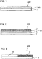
- the transfer layer 10 of the aspect shown in FIG. 1 has a single-layer structure composed only of a protective layer 5
- the transfer layer 10 of the aspect shown in FIG. 2 has a layered structure in which a protective layer 5 and an adhesive layer 6 are layered in this order from the side of the substrate 1.
- the protective layer 5 constituting the transfer layer 10 is a layer located on the outermost surface when the transfer layer 10 is transferred onto a transfer receiving article. Accordingly, in the case where the transfer layer 10 has a layered structure, the protective layer 5 is located nearest to a side of the substrate 1, among the layers constituting the transfer layer 10.
- each constituent of the protective layer transfer sheet 100 of the present disclosure will be explained.
- the material of the substrate 1 there is no limitation on the material of the substrate 1, and the material desirably has heat resistance and mechanical properties.
- examples can include various plastic films or sheets of polyesters such as polyethylene terephthalate, polycarbonate, polyimide, polyetherimide, cellulose derivatives, polyethylene, polypropylene, styrene resins, acrylic resins, polyvinyl chloride, polyvinylidene chloride, nylon, and polyether ether ketone.
- the thickness of the substrate 1 may be appropriately set depending on the kind of the material of the substrate 1, so that the strength and heat resistance lie in appropriate ranges. The thickness is generally 2.5 ⁇ m or more and 100 ⁇ m or less.
- the transfer layer 10 is provided on the substrate 1.
- the transfer layer 10 has a single-layer structure composed only of a protective layer 5 (see FIG. 1 ) or has a layered structure in which a protective layer 5 is located nearest to a side of the substrate 1 (see FIG. 2 ).
- the transfer layer 10 of the aspect shown in FIG. 2 has a layered structure in which the protective layer 5 and an adhesive layer 6 are layered in this order from the side of the substrate 1.
- the transfer layer 10 of the aspect shown in FIG. 3 includes both the single-layer structure and the layered structure, and a depiction of the protective layer 5 is omitted.
- the transfer layer 10 is not limited to the aspects shown and is only required to satisfy the condition that it includes the protective layer 5.
- the transfer layer 10 may have a structure in which a primer layer is provided between the protective layer 5 and the adhesive layer 6 in order to improve the adhesion between the protective layer 5 and the adhesive layer 6 or may have a structure in which various functional layers are provided on the protective layer 5.
- the protective layer 5 contains, as essential components, a styrene resin and particulate organofluorine compound particles.
- the particulate organofluorine compound may be referred to as organofluorine compound particles.
- the protective layer transfer sheet 100 of the present disclosure in which the protective layer 5 constituting the transfer layer 10 contains a styrene resin and organofluorine compound particles, it is possible to produce a print having good abrasion resistance and a good glossiness by transferring the transfer layer 10 including the protective layer 5 onto a transfer receiving article. In other words, it is possible to impart a good glossiness and abrasion resistance to the protective layer 5 by causing the protective layer 5 to contain a styrene resin and organofluorine compound particles.
- the styrene resin serves to impart a good glossiness to the protective layer 5
- the organofluorine compound particles serve to impart good abrasion resistance to the protective layer 5.
- the styrene resin referred to herein includes not only homopolymers of a styrene monomer but also copolymers of a styrene monomer and another monomer.
- the copolymerization ratio of the styrene monomer is preferably 50% or more.
- the copolymerization ratio referred to herein means a molar ratio.
- both the copolymerization ratio of the styrene monomer and the copolymerization ratio of the acrylic monomer are preferably 20% or more, and the copolymerization ratio of the styrene monomer is preferably 50% or more.
- the total of the copolymerization ratio of the styrene monomer and the copolymerization ratio of the acrylic monomer is preferably 80% or more.
- the acrylic monomer include acrylic monomers such as acrylic acid, methacrylic acid, acrylic acid esters, and methacrylic acid esters.
- the content of the styrene resin is not limited, but in the case where, as the styrene resin, a homopolymer of a styrene monomer or a copolymer of a styrene monomer and another monomer other than acrylic monomers is used, the content of the styrene resin is preferably 70% by mass or more, more preferably 90% by mass or more based on the total mass of the protective layer 5.
- the content of the styrene resin is preferably 10% by mass or more, more preferably 15% by mass or more, even more preferably 50% by mass or more based on the total mass of the protective layer 5. It is possible to impart a better glossiness to the protective layer 5 by setting the content of the styrene resin to the preferred content described above.
- the preferred upper limit value of the styrene resin is only required to be appropriately determined in accordance with the contents of the organofluorine compound particles and other optional components.
- organofluorine compound particles can include PTFE (polytetrafluoroethylene) particles, PFA (tetrafluoroethylene - perfluoroalkyl vinyl ether copolymer) particles, FEP (tetrafluoroethylene - hexafluoropropylene copolymer) particles, ETFE (tetrafluoroethylene - ethylene copolymer) particles, PVDF (polyvinylidene fluoride) particles, PCTFE (polychlorotrifluoroethylene) particles, and ECTFE (chlorotrifluoroethylene - ethylene copolymer) particles.
- PTFE polytetrafluoroethylene
- PFA tetrafluoroethylene - perfluoroalkyl vinyl ether copolymer
- FEP tetrafluoroethylene - hexafluoropropylene copolymer
- ETFE tetrafluoroethylene - ethylene copolymer
- PVDF poly
- PTFE particles are preferable organofluorine compound particles in respect of their capability of imparting better abrasion resistance to the protective layer 5.
- Other organofluorine compound particles than PTFE particles also may be used.
- the protective layer 5 may contain one type of these organofluorine compound particles singly or may contain two or more types of these organofluorine compound particles.
- the shape of the organofluorine compound particles may be any shape such as a spherical shape, a scaly shape, a flat shape, a spindle shape, a polygonal shape, a dome shape, or an amorphous shape.
- the shape may be other shapes than these.
- the protective layer 5 of the preferred aspect contains organofluorine compound particles having a particle size calculated by the following calculation method or a volume particle size D50 of 2 ⁇ m or more and 5 ⁇ m or less. It is possible to impart better abrasion resistance to the protective layer 5 while sufficiently maintaining the glossiness imparted to the protective layer 5 by causing the protective layer 5 to contain organofluorine compound particles having a particle size of 2 ⁇ m or more and 5 ⁇ m or less.
- the protective layer 5 it is possible to enhance the smoothness of the surface of the protective layer 5 on the side of the substrate 1 and to sufficiently maintain the glossiness of the protective layer 5 imparted by the styrene resin by causing the protective layer 5 to contain organofluorine compound particles having a particle size of 5 ⁇ m or less. Additionally, it is possible to impart better abrasion resistance to the protective layer 5 by causing the protective layer 5 to contain organofluorine compound particles having a volume particle size of 2 ⁇ m or more.
- the particle size of the organofluorine compound particles can be determined by a method of directly measuring the size of primary particles from a micrograph of a vertical cross section of the protective layer transfer sheet. Specifically, the minor axis diameter and major axis diameter of the primary particles are measured, and the average thereof is taken as the particle size of the primary particles. The particle size of 100 particles is measured in the same manner, and the average thereof is taken as the average particle size. The particle size to be calculated by the method of calculating the particle size means this average particle size. The same result can be obtained using either of a transmission electron microscope (TEM) or a scanning electron microscope (SEM).
- TEM transmission electron microscope
- SEM scanning electron microscope
- the volume particle size D50 referred to herein means the diameter of the particles at which the accumulated volume reaches 50% in a particle size distribution on a volume basis.
- the content of the organofluorine compound particles is preferably 2% by mass or more and 35% by mass or less based on the total mass of the protective layer 5. It is possible to impart better abrasion resistance to the protective layer 5 while sufficiently maintaining the glossiness imparted to the protective layer 5 by setting the content of the organofluorine compound particles to the preferred content described above. Specifically, it is possible to enhance the smoothness of the surface of the protective layer 5 on the side of the substrate 1 and to sufficiently maintain the glossiness of the protective layer 5 to be imparted by the styrene resin by setting the content of the organofluorine compound particles to 35% by mass or less. Additionally, it is possible to impart better abrasion resistance to the protective layer 5 by setting the content of the organofluorine compound particles to 2% by mass or more.
- the content of the organofluorine compound particles having a particle size of less than 3 ⁇ m is more preferably more than 10% by mass based on the total mass of the protective layer 5.
- the content of the organofluorine compound particles having a particle size of 3 ⁇ m or more and less than 4 ⁇ m is more preferably more than 3% by mass based on the total mass of the protective layer 5.
- the content of the organofluorine compound particles having a particle size of 4 ⁇ m or more is preferably 2% by mass or more based on the total mass of the protective layer 5.
- the particle size and the content of the organofluorine compound particles satisfy the preferred particle size and content described above.
- the protective layer 5 may also contain optional components together with the styrene resin and organofluorine compound particles as the essential components.
- the optional components can include polyvinyl chloride, polyvinyl acetate, polyesters, acrylic resins, polycarbonate, phenoxy resins, ultraviolet absorbing resins, epoxy resins, polyurethane, acryl-modified urethane resins, acryl urethane resins such as urethane-modified acrylic resins, resins obtained by silicone-modifying these resins, mixtures of these resins, ionizing radiation curable resins, and ultraviolet absorbing resins.
- the protective layer 5 containing a styrene - acrylic copolymer obtained by copolymerizing a styrene monomer as a styrene resin and an acrylic monomer will be described.
- the protective layer 5 containing a styrene - acrylic copolymer preferably further contains a vinyl chloride - vinyl acetate copolymer. According to the protective layer 5 of this aspect, it is possible to improve the adhesion between the transfer layer 10 and a constituent member in contact with the transfer layer 10, for example, the substrate 1. Thereby, it is possible to prevent unintentional fall-off of the transfer layer 10 from the side of the substrate 1 in advance of transferring the transfer layer 10.
- the protective layer 5 of this aspect is a suitable aspect in the case where the transfer layer 10 is provided directly on the substrate 1.
- the content of the styrene - acrylic copolymer and the content of the organofluorine compound particles are the preferred contents described above.
- the protective layer contains 6% by mass or more and 25% by mass or less of the vinyl chloride - vinyl acetate copolymer based on the total mass of the protective layer 5. According to the protective layer 5 of the preferred aspect, it is possible to improve the adhesion between the transfer layer 10 and a constituent member in contact with the transfer layer 10.
- the protective layer 5 containing a styrene - acrylic copolymer preferably contains a resin component having a glass transition temperature (Tg) of 60°C or less together with the vinyl chloride - vinyl acetate copolymer described above. While the adhesion between the transfer layer 10 and a constituent member in contact with the transfer layer 10 is improved by causing the protective layer 5 containing a styrene - acrylic copolymer to further contain a resin component having a glass transition temperature (Tg) of 60°C or less together with the vinyl chloride - vinyl acetate copolymer, it is possible to lower the adhesion between the transfer layer 10 and the constituent member in contact with the transfer layer 10 by application of energy during transfer of the transfer layer 10.
- Tg glass transition temperature
- the protective layer 5 containing a styrene - acrylic copolymer of the preferred aspect contains 6% by mass or more and 60% by mass or less, more preferably 6% by mass or more and 50% by mass or less of the resin component having a glass transition temperature (Tg) of 60°C or less based on the total mass of the protective layer 5.
- Tg glass transition temperature
- the glass transition temperature (Tg) referred to herein means a temperature determined by DSC (differential scanning calorimetry) in compliance with JIS-K-7121 (2012).
- the transfer layer 10 is caused to have a single-layer structure composed only of the protective layer 5 as shown in FIG. 1 , it is also possible to further enhance the adhesion between the transfer layer and a transfer receiving article by causing the protective layer 5 to contain a component having the adhesion between the transfer receiving article and the transfer layer 10.
- the styrene resin is a resin having adhesion, and thus, even in the case where the transfer layer 10 is caused to have a single-layer structure composed only of the protective layer 5, it is possible to transfer the transfer layer 10 onto a transfer receiving article.
- the component having adhesion components explained in the adhesive layer mentioned below can be appropriately selected and used.
- the protective layer 5 may be caused to contain various silicone oils, a polyethylene wax, a metal soap such as zinc stearate, zinc stearyl phosphate, calcium stearate, or magnesium stearate, a release agent such as fatty acid amide, polyethylene wax, carnauba wax, or paraffin wax, a known ultraviolet absorbing agent such as a benzophenone type, benzotriazole type, benzoate type, triazine type, titanium oxide, or zinc oxide ultraviolet absorbing agent, a light stabilizer such as a hindered amine type or Ni-chelate type light stabilizer, an antioxidant such as a hindered phenol type, sulfur type, phosphorus type, or lactone type antioxidant, and the like, as required.
- a polyethylene wax such as a metal soap such as zinc stearate, zinc stearyl phosphate, calcium stearate, or magnesium stearate
- a release agent such as fatty acid amide, polyethylene wax, carnauba wax, or paraffin
- the protective layer may be formed by dispersing or dissolving a styrene resin, organofluorine compound particles, and various additives to be used as required in a suitable solvent to prepare a coating liquid for protective layer, coating this coating liquid on the substrate 1 or an optional layer provided on the substrate 1 (e.g., a release layer to be mentioned below), and drying the coated liquid.
- a suitable solvent to prepare a coating liquid for protective layer
- the coating method include a gravure printing method, a screen printing method, and a reverse-coating method using a gravure printing plate. Coating methods other than these methods also may be used. The same applies to coating methods for various coating liquids described below.
- the thickness of the protective layer 5 is generally 0.5 ⁇ m or more and 10 ⁇ m or less.
- the thickness of the protective layer 5 is preferably 0.8 ⁇ m or more and 2 ⁇ m or less.
- the transfer layer 10 may be caused to have a layered structure in which the protective layer 5 and the adhesive layer 6 are layered in this order from the side of the substrate 1. According to the transfer layer 10 of this aspect, it is possible to impart better adhesion to the transfer layer 10 without causing the protective layer 5 to contain a component that imparts adhesion between the protective layer 5 and an transfer receiving article (component having adhesion).
- a component of the adhesive layer there is no particular limitation on a component of the adhesive layer, and examples thereof include polyurethanes, polyolefins such as ⁇ -olefin - maleic anhydride, polyesters, and resin components such as acrylic resins, epoxy resins, urea resins, melamine resins, phenol resins, polyvinyl acetate, vinyl chloride - vinyl acetate copolymers, and cyano acrylate resins.
- the thickness of the adhesive layer 6 is preferably 0.5 ⁇ m or more and 10 ⁇ m or less.
- the adhesive layer can be formed by dispersing or dissolving, for example, the adhesive exemplified above and additives to be added as required in a suitable solvent to prepare a coating liquid for adhesive layer, coating this coating liquid onto the protective layer 5 or an optional layer provided on the protective layer 5, and drying the coated liquid.
- a release layer (not shown) may be provided between the substrate 1 and the transfer layer 10.
- the components of the release layer may include waxes, silicone wax, silicone resins, silicone-modified resins, fluorine resins, fluorine-modified resins, polyvinyl alcohol, acrylic resins, thermally crosslinkable epoxy - amino resins, and thermally crosslinkable alkyd - amino resins.
- the thickness of the release layer is generally 0.5 ⁇ m or more and 5 ⁇ m or less.
- the release layer can be formed by, for example, dispersing or dissolving the components described above in a suitable solvent to prepare a coating liquid for release layer, coating this coating liquid on the substrate 1, and drying the coated liquid.
- the surface of the substrate 1 on the side of the release layer may be subjected to adhesive treatment in order to improve the adhesion between the substrate 1 and the release layer.
- adhesive treatment a known resin surface treatment technique can be applied as it is, for example, corona discharge treatment, flame treatment, ozone treatment, ultraviolet treatment, radiation treatment, roughening treatment, chemical treatment, plasma treatment, low temperature plasma treatment, primer treatment, and grafting treatment. Alternatively, two or more of these treatments may be used in combination.
- a colorant layer 7 and the transfer layer 10 described above may be disposed in any order on one surface of the substrate 1.
- a single colorant layer 7 is provided on one surface of the substrate 1.
- a plurality of colorant layers for example, a yellow colorant layer, a magenta colorant layer, a cyan colorant layer, a black colorant layer, and the like may be disposed in any order on one surface of the substrate.
- the protective layer transfer sheet of the aspect shown in FIG. 3 it is possible to form a thermal transferred image on a transfer receiving article and to transfer the transfer layer 10 onto the formed thermal transferred image using one protective layer transfer sheet 100.
- the colorant layer 7 contains a binder resin and a sublimable dye.
- the binder resin contained in the colorant layer 7 may include cellulosic resins such as ethyl cellulose, hydroxyethyl cellulose, ethyl hydroxy cellulose, methyl cellulose, and cellulose acetate, vinyl resins such as polyvinyl alcohol, polyvinyl acetate, polyvinyl butyral, polyvinyl acetoacetal, and polyvinyl pyrrolidone, acrylic resins such as poly(meth)acrylate and poly(meth)acrylamide, and resin components such as polyurethane, polyamide, and polyester.
- cellulosic resins such as ethyl cellulose, hydroxyethyl cellulose, ethyl hydroxy cellulose, methyl cellulose, and cellulose acetate
- vinyl resins such as polyvinyl alcohol, polyvinyl acetate, polyvinyl butyral, polyvinyl acetoace
- the content of the binder resin is preferably 20% by mass or more based on the total mass of the colorant layer 7. It is possible to sufficiently retain the sublimable dye in the colorant layer 7 to thereby improve the storage stability by setting the content of the binder resin to 20% by mass or more based on the total mass of the colorant layer.
- the upper limit value of the content of the binder resin is only required to be appropriately set in accordance with the content of the sublimable dye and optional additives.
- sublimable dyes having a sufficient coloring density and undergoing no discoloration or fading due to light, heat, temperature, or the like.
- the dye include diarylmethane type dyes, triarylmethane type dyes, thiazole type dyes, merocyanine dyes, pyrazolone dyes, methine type dyes, indoaniline type dyes, azomethine type dyes such as acetophenoneazomethine, pyrazoloazomethine, imidazoleazomethine, imidazoazomethine, and pyridoneazomethine, xanthene type dyes, oxazine type dyes, cyanostyrene type dyes such as dicyanostyrene and tricyanostyrene, thiazine type dyes, azine type dyes, acridine type dyes, benzeneazo type dyes,
- red dyes such as MS Red G (Mitsui Toatsu Chemicals, Inc.), Macrolex Red Violet R (Bayer AG), Ceres Red 7B (Bayer AG), and Samaron Red F3BS (Mitsubishi Chemical Corporation), yellow dyes such as Holon brilliant yellow 6GL (Clariant), PTY-52 (Mitsubishi Chemical Corporation), and Macrolex yellow 6G (Bayer AG), and blue dyes such as Kayaset(R) Blue 714 (Nippon Kayaku Co., Ltd.), Holon brilliant blue S-R (Clariant), MS blue 100 (Mitsui Toatsu Chemicals, Inc.), and C.I. solvent blue 63.
- red dyes such as MS Red G (Mitsui Toatsu Chemicals, Inc.), Macrolex Red Violet R (Bayer AG), Ceres Red 7B (Bayer AG), and Samaron Red F3BS (Mitsubishi Chemical Corporation)
- yellow dyes such as Holon brilliant yellow 6GL (Clariant), PTY-
- the content of the sublimable dye is preferably 50% by mass or more and 350% by mass or less, more preferably 80% by mass or more and 300% by mass or less based on the total mass of the binder resin. It is possible to further improve the printing density and storage stability by setting the content of the sublimable dye to the preferred content described above.
- a colorant primer layer (not shown) with a purpose of improving the adhesion between the substrate 1 and the colorant layer 7 may be provided between the substrate 1 and the colorant layer 7.
- a colorant primer layer as an example is constituted by a resin component.
- the resin component constituting the colorant primer layer may include resin components such as polyester, polyvinyl pyrrolidone, polyvinyl alcohol, polyacrylic acid esters, polyvinyl acetate, polyurethane, styrene - acrylic copolymers, polyacrylamide, polyamide, polyvinyl acetoacetal, and polyvinyl butyral.
- the colorant primer layer may also contain various additives such as organic particles and inorganic particles together with these resin components.
- the colorant primer layer can be formed by dispersing or dissolving the resin component exemplified above and additives to be added as required in a suitable solvent to prepare a coating liquid for colorant primer layer, coating this coating liquid on the substrate 1, and drying the coated liquid.
- the thickness of the colorant primer layer is generally 0.02 ⁇ m or more and 1 ⁇ m or less.
- a back face layer (not shown) may be provided on the other surface of the substrate 1.
- the back face layer is an optional constituent in the protective layer transfer sheet of the present disclosure.
- the back face layer may be formed by appropriately selecting and using resin(s) from the conventionally known thermoplastic resins and the like.
- a thermoplastic resin may include resin components such as polyesters, polyacrylic acid esters, polyvinyl acetate, styrene - acrylic copolymers, polyurethane, polyolefins such as polyethylene and polypropylene, styrene resins, polyvinyl chloride, polyethers, polyamides, polyimides, polyamide-imides, polycarbonate, polyacrylamide, polyvinyl chloride, polyvinyl acetals such as polyvinyl acetoacetal and polyvinyl butyral, and silicone-modified forms of these.
- polyamide-imides or silicone-modified forms thereof are preferably used, from the viewpoint of the heat resistance and the like.
- These resins may be those prepared by curing with a curing agent.
- the curing agent include isocyanate type curing agents.
- the back face layer preferably contains various additives, for instance, a release agent such as a wax, a higher fatty acid amide, a phosphoric ester compound, metal soaps, silicone oils, or a surfactant, an organic powder such as fluorine resin, and inorganic particles such as silica, clay, talc, or calcium carbonate, and particularly preferably contains at least one of a phosphoric ester or metal soap, in addition to the thermoplastic resin described, for the purpose of improving the slipping property.
- a release agent such as a wax, a higher fatty acid amide, a phosphoric ester compound, metal soaps, silicone oils, or a surfactant
- an organic powder such as fluorine resin
- inorganic particles such as silica, clay, talc, or calcium carbonate
- the back face layer can be formed by, for example, dispersing or dissolving the thermoplastic resin described above and various additives to be added as required in a suitable solvent to prepare a coating liquid for back face layer, coating this coating liquid onto the other surface of the substrate 1, and drying the coated liquid.
- the thickness of the back face layer is preferably 0.1 ⁇ m or more and 5 ⁇ m or less, more preferably 0.3 ⁇ m or more and 2 ⁇ m or less, from the viewpoint of improvement in the heat resistance and the like.
- Examples of a transfer receiving article onto which the transfer layer 10 of the protective layer transfer sheet 100 of the present disclosure is to be transferred include thermal transfer image-receiving sheets, plain paper, wood-free paper, tracing paper, plastic films, and plastic cards mainly composed of vinyl chloride, a vinyl chloride - vinyl acetate copolymer, or polycarbonate.
- the transfer receiving article ones having a predetermined image also can be used.
- the transfer receiving article may be colored or may have transparency.
- the method for transferring the transfer layer onto a transfer receiving article can be conducted using, for example, a thermal transfer printer having a heating device such as a thermal head, or a heating device such as hot stamping or a heat roll.
- a thermal transfer printer having a heating device such as a thermal head, or a heating device such as hot stamping or a heat roll.
- the resins and the like constituting each layer are exemplarily described herein. These resins may be homopolymers of a monomer constituting each resin or may be copolymers of a monomer as the main component constituting each resin and one or more other monomers or derivatives thereof.
- the resin in the case of a reference to an acrylic resin, the resin is only required to contain an acrylic acid or methacrylic acid monomer or an acrylate or methacrylate monomer as the main component.
- the resin also may be a modified form of these resins. Alternatively, other resins than those exemplarily described herein may be used.
- part or % means that by mass, representing a blend not in terms of solid content.
- a coating liquid for protective layer 1 having the following composition was coated onto a polyethylene terephthalate (PET) film having a thickness of 4.5 ⁇ m so as to obtain a thickness of 1 ⁇ m in the dried state, and the coated liquid was dried to form a protective layer.
- a coating liquid for adhesive layer having the following composition was coated onto the protective layer so as to obtain a thickness of 1 ⁇ m in the dried state, and the coated liquid was dried to obtain a protective layer transfer sheet of Example 1, in which the protective layer and the adhesive layer were layered in this order on the substrate.
- the reference to a transfer layer means a laminate of the protective layer and the adhesive layer.
- D50 described in Table 2 is a volume average particle size D50.
- ⁇ Coating liquid for protective layer 1 • Styrene resin (as resin (1)) 97 parts (CR3500, DIC Corporation) • Organofluorine compound particles (as particles (1)) (D50: 2.5 ⁇ m) 3 parts (KTL-1N, KITAMURA LIMITED) • Methyl ethyl ketone 200 parts • Toluene 200 parts ⁇ Coating liquid for adhesive layer> • Polyester 20 parts (Vylon(R) 200, TOYOBO CO., LTD.) • Ultraviolet absorbing resin 10 parts (UVA-635L, BASF Japan) • Methyl ethyl ketone 40 parts • Toluene 40 parts
- Example 2 The same procedure as described in Example 1 was repeated, except for replacing the styrene resin (resin (1)) and organofluorine compound particles (particles(1)) in the coating liquid for protective layer 1 by each of resins and particles shown in Table 1 below and forming the protective layer using coating liquids for protective layer in which the amount of each of the resins and particles blended was changed as shown in Table 1 below in order to prepare protective layer transfer sheets of Examples 2 to 35 and Comparative Examples 1 to 6. The details of the resins (1) to (6) and particles (1) to (6) in Table 1 are shown in Table 2. In the coating liquids for protective layer of Examples 2 to 35 and Comparative Examples 1 to 6, the solvent and the amount blended thereof are the same as in the coating liquid for protective layer 1.
- the solvent and the amount blended thereof are the same as in the coating liquid for protective layer 1.
- a genuine ribbon for a sublimable type thermal transfer printer (DS620, Dai Nippon Printing Co., Ltd.) having a yellow colorant layer, a magenta colorant layer, a cyan colorant layer, and a protective layer repeated in this order was prepared.
- the protective layer of the genuine ribbon was cut.
- the protective layer transfer sheet of each of Examples and Comparative Examples was located on the cut protective layer portion to thereby prepare a thermal transfer sheet of each of Examples and Comparative Examples, in which the protective layer transfer sheet of each of Examples and Comparative Examples located on the protective layer portion was linked to adjacent colorant layer portions. That is, the thermal transfer sheet of each of Examples and Comparative Examples was prepared in which only the protective layer portion of a genuine ribbon was replaced by the protective layer transfer sheet of each of Examples and Comparative Examples.
- a 0/255-graduation black solid image (image gray scale) was printed onto a genuine image-receiving paper for the sublimable type thermal transfer printer as a transfer receiving article using a sublimable type thermal transfer printer (DS620, Dai Nippon Printing Co., Ltd.) and the thermal transfer sheet of each of Examples and Comparative Examples prepared above to thereby obtain an image formed product.
- the transfer layer of the thermal transfer sheet of each of Examples and Comparative Examples was transferred onto the image formed product obtained above using the sublimable type thermal transfer printer described above to thereby obtain a print of each of Examples and Comparative Examples.
Landscapes
- Physics & Mathematics (AREA)
- Optics & Photonics (AREA)
- Laminated Bodies (AREA)
- Thermal Transfer Or Thermal Recording In General (AREA)
Abstract
Description
- The present invention relates to protective layer transfer sheets.
- Sublimable type thermal transfer methods have been widely used to form a thermal transferred image on a transfer receiving article because such methods can easily form high-quality images equivalent to conventional full-color photographic images and having excellent transparency and high reproducibility and high gradation of neutral tints. As prints in which a thermal transferred image has been formed on a transfer receiving article, there are known digital photographs, and identification (ID) cards, which are used in various fields, such as identity cards, driver's license cards, membership cards, and the like.
- Formation of a thermal transferred image by a sublimable type thermal transfer method is conducted by combining a thermal transfer sheet having a colorant layer provided on one surface of a substrate with a transfer receiving article, for example, a thermal transfer image-receiving sheet having a receiving layer provided on one surface of another substrate and applying energy onto the back side of the thermal transfer sheet with a heating device such as a thermal head to cause the colorant contained in the colorant layer to be transferred onto the transfer receiving article.
- However, the thermal transferred image formed by the sublimable type thermal transfer method described above has a disadvantage such as inferior durability including abrasion resistance because the colorant is not a pigment but a dye having a relatively low molecular weight. Then, usually, for a thermal transferred image formed by the sublimable type thermal transfer method, a protective layer transfer sheet having a protective layer is used to transfer the protective layer onto the thermal transferred image to thereby improve the durability. Recently, thermal transferred images having durability as well as a high glossiness have been highly required. In this case, the protective layer located on the outermost surface after transfer is required to have good durability and a good glossiness. As the protective layer transfer sheet, for example, those suggested in
Patent Literatures 1 and 2 are known. -
- Patent Literature 1: Japanese Patent Laid-Open No.
2005-262690 - Patent Literature 2: Japanese Patent Laid-Open No.
2002-240404 - The present invention has been made in view of such situations, and the present invention aims principally to provide a protective layer transfer sheet that can produce a print having good abrasion resistance and a good glossiness.
- A protective layer transfer sheet according to an embodiment of the present disclosure for solving the above problems has a transfer layer provided on one surface of a substrate, the transfer layer has a single-layer structure composed only of a protective layer or a layered structure in which the protective layer is located nearest to a side of the substrate, and the protective layer contains a styrene resin and a particulate organofluorine compound.
- Additionally, the particulate organofluorine compound may have a particle size of 2 µm or more and 5 µm or less.
- The content of the particulate organofluorine compound may be 2% by mass or more and 35% by mass or less based on the total mass of the protective layer.
- According to the protective layer transfer sheet of the present disclosure, it is possible to produce a print having good abrasion resistance and a good glossiness by transferring the transfer layer.
-
-
FIG. 1 is a schematic sectional view illustrating one example of a protective layer transfer sheet of the present disclosure. -
FIG. 2 is a schematic sectional view illustrating one example of a protective layer transfer sheet of the present disclosure. -
FIG. 3 is a schematic sectional view illustrating one example of a protective layer transfer sheet of the present disclosure. - Hereinafter, a protective
layer transfer sheet 100 according to an embodiment of the present disclosure (hereinafter, it is referred to as the protective layer transfer sheet of the present disclosure) will be described concretely using drawings. - As shown in
FIGS. 1 to 3 , the protectivelayer transfer sheet 100 of the present disclosure includes asubstrate 1 and atransfer layer 10 provided on thesubstrate 1. Thetransfer layer 10 is a layer that is peeled at the surface of thetransfer layer 10 on the side of thesubstrate 1 and is transferred onto a transfer receiving article. - The
transfer layer 10 is a single-layer structure composed only of a protective layer or is composed of a plurality of layers including a protective layer. Thetransfer layer 10 of the aspect shown inFIG. 1 has a single-layer structure composed only of aprotective layer 5, and thetransfer layer 10 of the aspect shown inFIG. 2 has a layered structure in which aprotective layer 5 and anadhesive layer 6 are layered in this order from the side of thesubstrate 1. Note that theprotective layer 5 constituting thetransfer layer 10 is a layer located on the outermost surface when thetransfer layer 10 is transferred onto a transfer receiving article. Accordingly, in the case where thetransfer layer 10 has a layered structure, theprotective layer 5 is located nearest to a side of thesubstrate 1, among the layers constituting thetransfer layer 10. Hereinafter, each constituent of the protectivelayer transfer sheet 100 of the present disclosure will be explained. - The
substrate 1, which is an essential constituent in the protectivelayer transfer sheet 100 of the present disclosure, includes thetransfer layer 10 and the like. There is no limitation on the material of thesubstrate 1, and the material desirably has heat resistance and mechanical properties. As thesubstrate 1 like this, examples can include various plastic films or sheets of polyesters such as polyethylene terephthalate, polycarbonate, polyimide, polyetherimide, cellulose derivatives, polyethylene, polypropylene, styrene resins, acrylic resins, polyvinyl chloride, polyvinylidene chloride, nylon, and polyether ether ketone. The thickness of thesubstrate 1 may be appropriately set depending on the kind of the material of thesubstrate 1, so that the strength and heat resistance lie in appropriate ranges. The thickness is generally 2.5 µm or more and 100 µm or less. - As shown in
FIGS. 1 to 3 , thetransfer layer 10 is provided on thesubstrate 1. Thetransfer layer 10 has a single-layer structure composed only of a protective layer 5 (seeFIG. 1 ) or has a layered structure in which aprotective layer 5 is located nearest to a side of the substrate 1 (seeFIG. 2 ). Note that thetransfer layer 10 of the aspect shown inFIG. 2 has a layered structure in which theprotective layer 5 and anadhesive layer 6 are layered in this order from the side of thesubstrate 1. Thetransfer layer 10 of the aspect shown inFIG. 3 includes both the single-layer structure and the layered structure, and a depiction of theprotective layer 5 is omitted. Thetransfer layer 10 is not limited to the aspects shown and is only required to satisfy the condition that it includes theprotective layer 5. For example, in the aspect shown inFIG. 2 , thetransfer layer 10 may have a structure in which a primer layer is provided between theprotective layer 5 and theadhesive layer 6 in order to improve the adhesion between theprotective layer 5 and theadhesive layer 6 or may have a structure in which various functional layers are provided on theprotective layer 5. - The
protective layer 5 contains, as essential components, a styrene resin and particulate organofluorine compound particles. Hereinafter, the particulate organofluorine compound may be referred to as organofluorine compound particles. - According to the protective
layer transfer sheet 100 of the present disclosure, in which theprotective layer 5 constituting thetransfer layer 10 contains a styrene resin and organofluorine compound particles, it is possible to produce a print having good abrasion resistance and a good glossiness by transferring thetransfer layer 10 including theprotective layer 5 onto a transfer receiving article. In other words, it is possible to impart a good glossiness and abrasion resistance to theprotective layer 5 by causing theprotective layer 5 to contain a styrene resin and organofluorine compound particles. - In the protective
layer transfer sheet 100 of the present disclosure, the styrene resin serves to impart a good glossiness to theprotective layer 5, and the organofluorine compound particles serve to impart good abrasion resistance to theprotective layer 5. - The styrene resin referred to herein includes not only homopolymers of a styrene monomer but also copolymers of a styrene monomer and another monomer. In the case where, as the styrene resin, a copolymer of a styrene monomer and another polymer other than an acrylic monomer is used, in other words, in the case where the styrene resin does not contain an acrylic monomer as a constituent monomer, the copolymerization ratio of the styrene monomer is preferably 50% or more. The copolymerization ratio referred to herein means a molar ratio.
- On the other hand, in the case where as the styrene resin, a copolymer of a styrene monomer and an acrylic monomer is used, in other words, in the case where the styrene resin contains an acrylic monomer as a constituent monomer, both the copolymerization ratio of the styrene monomer and the copolymerization ratio of the acrylic monomer are preferably 20% or more, and the copolymerization ratio of the styrene monomer is preferably 50% or more. The total of the copolymerization ratio of the styrene monomer and the copolymerization ratio of the acrylic monomer is preferably 80% or more. Examples of the acrylic monomer include acrylic monomers such as acrylic acid, methacrylic acid, acrylic acid esters, and methacrylic acid esters.
- The content of the styrene resin is not limited, but in the case where, as the styrene resin, a homopolymer of a styrene monomer or a copolymer of a styrene monomer and another monomer other than acrylic monomers is used, the content of the styrene resin is preferably 70% by mass or more, more preferably 90% by mass or more based on the total mass of the
protective layer 5. On the other hand, in the case where, as the styrene resin, a copolymer of a styrene monomer and an acrylic monomer (styrene - acrylic copolymer) is used, the content of the styrene resin is preferably 10% by mass or more, more preferably 15% by mass or more, even more preferably 50% by mass or more based on the total mass of theprotective layer 5. It is possible to impart a better glossiness to theprotective layer 5 by setting the content of the styrene resin to the preferred content described above. The preferred upper limit value of the styrene resin is only required to be appropriately determined in accordance with the contents of the organofluorine compound particles and other optional components. - Examples of the organofluorine compound particles can include PTFE (polytetrafluoroethylene) particles, PFA (tetrafluoroethylene - perfluoroalkyl vinyl ether copolymer) particles, FEP (tetrafluoroethylene - hexafluoropropylene copolymer) particles, ETFE (tetrafluoroethylene - ethylene copolymer) particles, PVDF (polyvinylidene fluoride) particles, PCTFE (polychlorotrifluoroethylene) particles, and ECTFE (chlorotrifluoroethylene - ethylene copolymer) particles. Among these, PTFE particles are preferable organofluorine compound particles in respect of their capability of imparting better abrasion resistance to the
protective layer 5. Other organofluorine compound particles than PTFE particles also may be used. Theprotective layer 5 may contain one type of these organofluorine compound particles singly or may contain two or more types of these organofluorine compound particles. - There is no particular limitation on the particle shape of the organofluorine compound particles. The shape thereof may be any shape such as a spherical shape, a scaly shape, a flat shape, a spindle shape, a polygonal shape, a dome shape, or an amorphous shape. The shape may be other shapes than these.
- There is no limitation on the particle size of the organofluorine compound particles, and the particle size is only required to be appropriately determined in accordance with the thickness of the
protective layer 5 and the content of the organofluorine compound particles. Theprotective layer 5 of the preferred aspect contains organofluorine compound particles having a particle size calculated by the following calculation method or a volume particle size D50 of 2 µm or more and 5 µm or less. It is possible to impart better abrasion resistance to theprotective layer 5 while sufficiently maintaining the glossiness imparted to theprotective layer 5 by causing theprotective layer 5 to contain organofluorine compound particles having a particle size of 2 µm or more and 5 µm or less. Specifically, it is possible to enhance the smoothness of the surface of theprotective layer 5 on the side of thesubstrate 1 and to sufficiently maintain the glossiness of theprotective layer 5 imparted by the styrene resin by causing theprotective layer 5 to contain organofluorine compound particles having a particle size of 5 µm or less. Additionally, it is possible to impart better abrasion resistance to theprotective layer 5 by causing theprotective layer 5 to contain organofluorine compound particles having a volume particle size of 2 µm or more. - The particle size of the organofluorine compound particles can be determined by a method of directly measuring the size of primary particles from a micrograph of a vertical cross section of the protective layer transfer sheet. Specifically, the minor axis diameter and major axis diameter of the primary particles are measured, and the average thereof is taken as the particle size of the primary particles. The particle size of 100 particles is measured in the same manner, and the average thereof is taken as the average particle size. The particle size to be calculated by the method of calculating the particle size means this average particle size. The same result can be obtained using either of a transmission electron microscope (TEM) or a scanning electron microscope (SEM).
- The volume particle size D50 referred to herein means the diameter of the particles at which the accumulated volume reaches 50% in a particle size distribution on a volume basis.
- There is no limitation on the content of the organofluorine compound particles, and the content of the organofluorine compound particles is preferably 2% by mass or more and 35% by mass or less based on the total mass of the
protective layer 5. It is possible to impart better abrasion resistance to theprotective layer 5 while sufficiently maintaining the glossiness imparted to theprotective layer 5 by setting the content of the organofluorine compound particles to the preferred content described above. Specifically, it is possible to enhance the smoothness of the surface of theprotective layer 5 on the side of thesubstrate 1 and to sufficiently maintain the glossiness of theprotective layer 5 to be imparted by the styrene resin by setting the content of the organofluorine compound particles to 35% by mass or less. Additionally, it is possible to impart better abrasion resistance to theprotective layer 5 by setting the content of the organofluorine compound particles to 2% by mass or more. - In the case where
protective layer 5 contains the organofluorine compound particles having a particle size of less than 3 µm, the content of the organofluorine compound particles having a particle size of less than 3 µm is more preferably more than 10% by mass based on the total mass of theprotective layer 5. In the case where theprotective layer 5 contains an organofluorine compound having a particle size of 3 µm or more and less than 4 µm, the content of the organofluorine compound particles having a particle size of 3 µm or more and less than 4 µm is more preferably more than 3% by mass based on the total mass of theprotective layer 5. In the case where theprotective layer 5 contains an organofluorine compound having a particle size of 4 µm or more, the content of the organofluorine compound particles having a particle size of 4 µm or more is preferably 2% by mass or more based on the total mass of theprotective layer 5. - In the
protective layer 5 of a more preferred aspect, the particle size and the content of the organofluorine compound particles satisfy the preferred particle size and content described above. - The
protective layer 5 may also contain optional components together with the styrene resin and organofluorine compound particles as the essential components. Examples of the optional components can include polyvinyl chloride, polyvinyl acetate, polyesters, acrylic resins, polycarbonate, phenoxy resins, ultraviolet absorbing resins, epoxy resins, polyurethane, acryl-modified urethane resins, acryl urethane resins such as urethane-modified acrylic resins, resins obtained by silicone-modifying these resins, mixtures of these resins, ionizing radiation curable resins, and ultraviolet absorbing resins. - Subsequently, one example of the
protective layer 5 containing a styrene - acrylic copolymer obtained by copolymerizing a styrene monomer as a styrene resin and an acrylic monomer will be described. - The
protective layer 5 containing a styrene - acrylic copolymer preferably further contains a vinyl chloride - vinyl acetate copolymer. According to theprotective layer 5 of this aspect, it is possible to improve the adhesion between thetransfer layer 10 and a constituent member in contact with thetransfer layer 10, for example, thesubstrate 1. Thereby, it is possible to prevent unintentional fall-off of thetransfer layer 10 from the side of thesubstrate 1 in advance of transferring thetransfer layer 10. Theprotective layer 5 of this aspect is a suitable aspect in the case where thetransfer layer 10 is provided directly on thesubstrate 1. In theprotective layer 5 of the preferred aspect containing a styrene - acrylic copolymer, the content of the styrene - acrylic copolymer and the content of the organofluorine compound particles are the preferred contents described above. The protective layer contains 6% by mass or more and 25% by mass or less of the vinyl chloride - vinyl acetate copolymer based on the total mass of theprotective layer 5. According to theprotective layer 5 of the preferred aspect, it is possible to improve the adhesion between thetransfer layer 10 and a constituent member in contact with thetransfer layer 10. - The
protective layer 5 containing a styrene - acrylic copolymer preferably contains a resin component having a glass transition temperature (Tg) of 60°C or less together with the vinyl chloride - vinyl acetate copolymer described above. While the adhesion between thetransfer layer 10 and a constituent member in contact with thetransfer layer 10 is improved by causing theprotective layer 5 containing a styrene - acrylic copolymer to further contain a resin component having a glass transition temperature (Tg) of 60°C or less together with the vinyl chloride - vinyl acetate copolymer, it is possible to lower the adhesion between thetransfer layer 10 and the constituent member in contact with thetransfer layer 10 by application of energy during transfer of thetransfer layer 10. Thereby, it is possible to improve the transferability of thetransfer layer 10. In theprotective layer 5 containing a styrene - acrylic copolymer of the preferred aspect, the contents of the styrene - acrylic copolymer, the organofluorine compound particles, and the vinyl chloride - vinyl acetate copolymer are the preferred contents described above. Theprotective layer 5 contains 6% by mass or more and 60% by mass or less, more preferably 6% by mass or more and 50% by mass or less of the resin component having a glass transition temperature (Tg) of 60°C or less based on the total mass of theprotective layer 5. - The glass transition temperature (Tg) referred to herein means a temperature determined by DSC (differential scanning calorimetry) in compliance with JIS-K-7121 (2012).
- In the case where the
transfer layer 10 is caused to have a single-layer structure composed only of theprotective layer 5 as shown inFIG. 1 , it is also possible to further enhance the adhesion between the transfer layer and a transfer receiving article by causing theprotective layer 5 to contain a component having the adhesion between the transfer receiving article and thetransfer layer 10. The styrene resin is a resin having adhesion, and thus, even in the case where thetransfer layer 10 is caused to have a single-layer structure composed only of theprotective layer 5, it is possible to transfer thetransfer layer 10 onto a transfer receiving article. As the component having adhesion, components explained in the adhesive layer mentioned below can be appropriately selected and used. - The
protective layer 5 may be caused to contain various silicone oils, a polyethylene wax, a metal soap such as zinc stearate, zinc stearyl phosphate, calcium stearate, or magnesium stearate, a release agent such as fatty acid amide, polyethylene wax, carnauba wax, or paraffin wax, a known ultraviolet absorbing agent such as a benzophenone type, benzotriazole type, benzoate type, triazine type, titanium oxide, or zinc oxide ultraviolet absorbing agent, a light stabilizer such as a hindered amine type or Ni-chelate type light stabilizer, an antioxidant such as a hindered phenol type, sulfur type, phosphorus type, or lactone type antioxidant, and the like, as required. - There is no particular limitation on the method for forming the
protective layer 5. The protective layer may be formed by dispersing or dissolving a styrene resin, organofluorine compound particles, and various additives to be used as required in a suitable solvent to prepare a coating liquid for protective layer, coating this coating liquid on thesubstrate 1 or an optional layer provided on the substrate 1 (e.g., a release layer to be mentioned below), and drying the coated liquid. Examples of the coating method include a gravure printing method, a screen printing method, and a reverse-coating method using a gravure printing plate. Coating methods other than these methods also may be used. The same applies to coating methods for various coating liquids described below. - There is no particular limitation on the thickness of the
protective layer 5, and the thickness is generally 0.5 µm or more and 10 µm or less. In the case where theprotective layer 5 is caused to contain the organofluorine compound particles having a preferred particle size described above, the thickness of theprotective layer 5 is preferably 0.8 µm or more and 2 µm or less. - As shown in
FIG. 2 , thetransfer layer 10 may be caused to have a layered structure in which theprotective layer 5 and theadhesive layer 6 are layered in this order from the side of thesubstrate 1. According to thetransfer layer 10 of this aspect, it is possible to impart better adhesion to thetransfer layer 10 without causing theprotective layer 5 to contain a component that imparts adhesion between theprotective layer 5 and an transfer receiving article (component having adhesion). - There is no particular limitation on a component of the adhesive layer, and examples thereof include polyurethanes, polyolefins such as α-olefin - maleic anhydride, polyesters, and resin components such as acrylic resins, epoxy resins, urea resins, melamine resins, phenol resins, polyvinyl acetate, vinyl chloride - vinyl acetate copolymers, and cyano acrylate resins.
- The thickness of the
adhesive layer 6 is preferably 0.5 µm or more and 10 µm or less. There is no limitation on the method for forming the adhesive layer. The adhesive layer can be formed by dispersing or dissolving, for example, the adhesive exemplified above and additives to be added as required in a suitable solvent to prepare a coating liquid for adhesive layer, coating this coating liquid onto theprotective layer 5 or an optional layer provided on theprotective layer 5, and drying the coated liquid. - A release layer (not shown) may be provided between the
substrate 1 and thetransfer layer 10. Examples of the components of the release layer may include waxes, silicone wax, silicone resins, silicone-modified resins, fluorine resins, fluorine-modified resins, polyvinyl alcohol, acrylic resins, thermally crosslinkable epoxy - amino resins, and thermally crosslinkable alkyd - amino resins. - The thickness of the release layer is generally 0.5 µm or more and 5 µm or less. There is no limitation on the method for forming the release layer, and the release layer can be formed by, for example, dispersing or dissolving the components described above in a suitable solvent to prepare a coating liquid for release layer, coating this coating liquid on the
substrate 1, and drying the coated liquid. - In the case where the release layer is provided on the
substrate 1, the surface of thesubstrate 1 on the side of the release layer may be subjected to adhesive treatment in order to improve the adhesion between thesubstrate 1 and the release layer. As the adhesive treatment, a known resin surface treatment technique can be applied as it is, for example, corona discharge treatment, flame treatment, ozone treatment, ultraviolet treatment, radiation treatment, roughening treatment, chemical treatment, plasma treatment, low temperature plasma treatment, primer treatment, and grafting treatment. Alternatively, two or more of these treatments may be used in combination. - As shown in
FIG. 3 , acolorant layer 7 and thetransfer layer 10 described above may be disposed in any order on one surface of thesubstrate 1. In the protectivelayer transfer sheet 100 of the aspect shown inFIG. 3 , asingle colorant layer 7 is provided on one surface of thesubstrate 1. Alternatively, a plurality of colorant layers, for example, a yellow colorant layer, a magenta colorant layer, a cyan colorant layer, a black colorant layer, and the like may be disposed in any order on one surface of the substrate. When thecolorant layer 7 and thetransfer layer 10 are taken as "one unit", the "one unit" may be provided repeatedly on one surface of thesubstrate 1. - According to the protective layer transfer sheet of the aspect shown in
FIG. 3 , it is possible to form a thermal transferred image on a transfer receiving article and to transfer thetransfer layer 10 onto the formed thermal transferred image using one protectivelayer transfer sheet 100. - The
colorant layer 7 as an example contains a binder resin and a sublimable dye. There is no particular limitation on the binder resin contained in thecolorant layer 7, and conventional known binder resins in the field of colorant layers can be appropriately selected and used. Examples of the binder resin in thecolorant layer 7 may include cellulosic resins such as ethyl cellulose, hydroxyethyl cellulose, ethyl hydroxy cellulose, methyl cellulose, and cellulose acetate, vinyl resins such as polyvinyl alcohol, polyvinyl acetate, polyvinyl butyral, polyvinyl acetoacetal, and polyvinyl pyrrolidone, acrylic resins such as poly(meth)acrylate and poly(meth)acrylamide, and resin components such as polyurethane, polyamide, and polyester. - There is no particular limitation on the content of the binder resin, and the content of the binder resin is preferably 20% by mass or more based on the total mass of the
colorant layer 7. It is possible to sufficiently retain the sublimable dye in thecolorant layer 7 to thereby improve the storage stability by setting the content of the binder resin to 20% by mass or more based on the total mass of the colorant layer. There is no particular limitation on the upper limit value of the content of the binder resin, and the upper limit value is only required to be appropriately set in accordance with the content of the sublimable dye and optional additives. - There is no particular limitation on the sublimable dye contained in the
colorant layer 7. Preferred are sublimable dyes having a sufficient coloring density and undergoing no discoloration or fading due to light, heat, temperature, or the like. Examples of the dye include diarylmethane type dyes, triarylmethane type dyes, thiazole type dyes, merocyanine dyes, pyrazolone dyes, methine type dyes, indoaniline type dyes, azomethine type dyes such as acetophenoneazomethine, pyrazoloazomethine, imidazoleazomethine, imidazoazomethine, and pyridoneazomethine, xanthene type dyes, oxazine type dyes, cyanostyrene type dyes such as dicyanostyrene and tricyanostyrene, thiazine type dyes, azine type dyes, acridine type dyes, benzeneazo type dyes, azo type dyes such as pyridonazo, thiophenazo, isothiazoleazo, pyrroleazo, pyrazoleazo, imidazoleazo, thiadiazoleazo, triazoleazo, and disazo, spiropyran type dyes, indolinospiropyran type dyes, fluoran type dyes, rhodaminelactam type dyes, naphthoquinone type dyes, anthraquinone type dyes, and quinophthalone type dyes. Specific examples may include red dyes such as MS Red G (Mitsui Toatsu Chemicals, Inc.), Macrolex Red Violet R (Bayer AG), Ceres Red 7B (Bayer AG), and Samaron Red F3BS (Mitsubishi Chemical Corporation), yellow dyes such as Holon brilliant yellow 6GL (Clariant), PTY-52 (Mitsubishi Chemical Corporation), and Macrolex yellow 6G (Bayer AG), and blue dyes such as Kayaset(R) Blue 714 (Nippon Kayaku Co., Ltd.), Holon brilliant blue S-R (Clariant), MS blue 100 (Mitsui Toatsu Chemicals, Inc.), and C.I. solvent blue 63. - The content of the sublimable dye is preferably 50% by mass or more and 350% by mass or less, more preferably 80% by mass or more and 300% by mass or less based on the total mass of the binder resin. It is possible to further improve the printing density and storage stability by setting the content of the sublimable dye to the preferred content described above.
- A colorant primer layer (not shown) with a purpose of improving the adhesion between the
substrate 1 and thecolorant layer 7 may be provided between thesubstrate 1 and thecolorant layer 7. - There is no particular limitation on the colorant primer layer, and conventionally known colorant primer layers in the field of thermal transfer sheets can be appropriately selected and used. A colorant primer layer as an example is constituted by a resin component. Examples of the resin component constituting the colorant primer layer may include resin components such as polyester, polyvinyl pyrrolidone, polyvinyl alcohol, polyacrylic acid esters, polyvinyl acetate, polyurethane, styrene - acrylic copolymers, polyacrylamide, polyamide, polyvinyl acetoacetal, and polyvinyl butyral. The colorant primer layer may also contain various additives such as organic particles and inorganic particles together with these resin components.
- There is also no particular limitation on the method for forming the colorant primer layer, and the colorant primer layer can be formed by dispersing or dissolving the resin component exemplified above and additives to be added as required in a suitable solvent to prepare a coating liquid for colorant primer layer, coating this coating liquid on the
substrate 1, and drying the coated liquid. There is no particular limitation on the thickness of the colorant primer layer, and the thickness is generally 0.02 µm or more and 1 µm or less. - A back face layer (not shown) may be provided on the other surface of the
substrate 1. Incidentally, the back face layer is an optional constituent in the protective layer transfer sheet of the present disclosure. - The back face layer may be formed by appropriately selecting and using resin(s) from the conventionally known thermoplastic resins and the like. Examples of such a thermoplastic resin may include resin components such as polyesters, polyacrylic acid esters, polyvinyl acetate, styrene - acrylic copolymers, polyurethane, polyolefins such as polyethylene and polypropylene, styrene resins, polyvinyl chloride, polyethers, polyamides, polyimides, polyamide-imides, polycarbonate, polyacrylamide, polyvinyl chloride, polyvinyl acetals such as polyvinyl acetoacetal and polyvinyl butyral, and silicone-modified forms of these. Among them, polyamide-imides or silicone-modified forms thereof are preferably used, from the viewpoint of the heat resistance and the like. These resins may be those prepared by curing with a curing agent. Examples of the curing agent include isocyanate type curing agents.
- Further, the back face layer preferably contains various additives, for instance, a release agent such as a wax, a higher fatty acid amide, a phosphoric ester compound, metal soaps, silicone oils, or a surfactant, an organic powder such as fluorine resin, and inorganic particles such as silica, clay, talc, or calcium carbonate, and particularly preferably contains at least one of a phosphoric ester or metal soap, in addition to the thermoplastic resin described, for the purpose of improving the slipping property.
- The back face layer can be formed by, for example, dispersing or dissolving the thermoplastic resin described above and various additives to be added as required in a suitable solvent to prepare a coating liquid for back face layer, coating this coating liquid onto the other surface of the
substrate 1, and drying the coated liquid. The thickness of the back face layer is preferably 0.1 µm or more and 5 µm or less, more preferably 0.3 µm or more and 2 µm or less, from the viewpoint of improvement in the heat resistance and the like. - Examples of a transfer receiving article onto which the
transfer layer 10 of the protectivelayer transfer sheet 100 of the present disclosure is to be transferred include thermal transfer image-receiving sheets, plain paper, wood-free paper, tracing paper, plastic films, and plastic cards mainly composed of vinyl chloride, a vinyl chloride - vinyl acetate copolymer, or polycarbonate. As the transfer receiving article, ones having a predetermined image also can be used. The transfer receiving article may be colored or may have transparency. - There is no particular limitation on the method for transferring the transfer layer onto a transfer receiving article, and the method can be conducted using, for example, a thermal transfer printer having a heating device such as a thermal head, or a heating device such as hot stamping or a heat roll.
- The resins and the like constituting each layer are exemplarily described herein. These resins may be homopolymers of a monomer constituting each resin or may be copolymers of a monomer as the main component constituting each resin and one or more other monomers or derivatives thereof. For example, in the case of a reference to an acrylic resin, the resin is only required to contain an acrylic acid or methacrylic acid monomer or an acrylate or methacrylate monomer as the main component. The resin also may be a modified form of these resins. Alternatively, other resins than those exemplarily described herein may be used.
- Next, the present invention will be described more concretely with reference to Examples and Comparative Examples. Hereinbelow, unless otherwise particularly specified, the expression of part or % means that by mass, representing a blend not in terms of solid content.
- A coating liquid for
protective layer 1 having the following composition was coated onto a polyethylene terephthalate (PET) film having a thickness of 4.5 µm so as to obtain a thickness of 1 µm in the dried state, and the coated liquid was dried to form a protective layer. Then, a coating liquid for adhesive layer having the following composition was coated onto the protective layer so as to obtain a thickness of 1 µm in the dried state, and the coated liquid was dried to obtain a protective layer transfer sheet of Example 1, in which the protective layer and the adhesive layer were layered in this order on the substrate. Hereinafter, the reference to a transfer layer means a laminate of the protective layer and the adhesive layer. D50 described in Table 2 is a volume average particle size D50.<Coating liquid for protective layer 1>• Styrene resin (as resin (1)) 97 parts (CR3500, DIC Corporation) • Organofluorine compound particles (as particles (1)) (D50: 2.5 µm) 3 parts (KTL-1N, KITAMURA LIMITED) • Methyl ethyl ketone 200 parts • Toluene 200 parts <Coating liquid for adhesive layer> • Polyester 20 parts (Vylon(R) 200, TOYOBO CO., LTD.) • Ultraviolet absorbing resin 10 parts (UVA-635L, BASF Japan) • Methyl ethyl ketone 40 parts • Toluene 40 parts - The same procedure as described in Example 1 was repeated, except for replacing the styrene resin (resin (1)) and organofluorine compound particles (particles(1)) in the coating liquid for
protective layer 1 by each of resins and particles shown in Table 1 below and forming the protective layer using coating liquids for protective layer in which the amount of each of the resins and particles blended was changed as shown in Table 1 below in order to prepare protective layer transfer sheets of Examples 2 to 35 and Comparative Examples 1 to 6. The details of the resins (1) to (6) and particles (1) to (6) in Table 1 are shown in Table 2. In the coating liquids for protective layer of Examples 2 to 35 and Comparative Examples 1 to 6, the solvent and the amount blended thereof are the same as in the coating liquid forprotective layer 1.[Table 1] Coating liquid for protective layer Binder Particles Type Amount blended (parts) Type Amount blended (parts) Type Amount blended (parts) Type Amount blended (parts) Example 1 Resin (1) 97 - Particles (1) 3 Example 2 Resin (1) 95 - Particles (1) 5 Example 3 Resin (1) 90 - Particles (1) 10 Example 4 Resin (1) 85 - Particles (1) 15 Example 5 Resin (1) 80 - Particles (1) 20 Example 6 Resin (1) 70 - Particles (1) 30 Example 7 Resin (1) 99 - Particles (2) 1 Example 8 Resin (1) 97 - Particles (2) 3 Example 9 Resin (1) 95 - Particles (2) 5 Example 10 Resin (1) 90 - Particles (2) 10 Example 11 Resin (1) 85 - Particles (2) 15 Example 12 Resin (1) 80 - Particles (2) 20 Example 13 Resin (1) 70 - Particles (2) 30 Example 14 Resin (1) 60 - Particles (2) 40 Example 15 Resin (1) 97 - Particles (3) 3 Example 16 Resin (1) 95 - Particles (3) 5 Example 17 Resin (1) 90 - Particles (3) 10 Example 18 Resin (1) 85 - Particles (3) 15 Example 19 Resin (1) 80 - Particles (3) 20 Example 20 Resin (1) 70 - Particles (3) 30 Example 21 Resin (1) 77 Resin (2) 10 Resin (3) 10 Particles (2) 3 Example 22 Resin (1) 87 Resin (2) 10 - Particles (2) 3 Example 23 Resin (1) 87 Resin (3) 10 - Particles (2) 3 Example 24 Resin (5) 97 - Particles (2) 3 Example 25 Resin (6) 97 - Particles (2) 3 Example 26 Resin (6) 92 Resin (2) 5 - Particles (2) 3 Example 27 Resin (6) 87 Resin (2) 10 - Particles (2) 3 Example 28 Resin (6) 87 Resin (2) 5 Resin (3) 5 Particles (2) 3 Example 29 Resin (6) 77 Resin (2) 10 Resin (3) 10 Particles (2) 3 Example 30 Resin (6) 57 Resin (2) 20 Resin (3) 20 Particles (2) 3 Example 31 Resin (6) 33 Resin (2) 32 Resin (3) 32 Particles (2) 3 Example 32 Resin (6) 45 Resin (2) 20 Resin (3) 32 Particles (2) 3 Example 33 Resin (6) 20 Resin (2) 20 Resin (3) 57 Particles (2) 3 Example 34 Resin (6) 87 Resin (3) 10 Particles (2) 3 Example 35 Resin (6) 77 Resin (2) 10 Resin (4) 10 Particles (2) 3 Comparative Example 1 Resin (1) 100 - - 0 Comparative Example 2 Resin (1) 97 - Particles (4) 3 Comparative Example 3 Resin (1) 95 - Particles (4) 5 Comparative Example 4 Resin (7) 100 - - 0 Comparative Example 5 Resin (7) 97 - Particles (4) 3 Comparative Example 6 Resin (7) 95 - Particles (4) 5 [Table 2] Type Component Component details Resin (1) Styrene resin CR3500, DIC Corporation Resin (2) Vinyl chloride - vinyl acetate copolymer SOLBIN(R) CNL, Nissin Chemical Co., Ltd. Resin (3) Acrylic resin (Tg: 56°C) MB-2539, Mitsubishi Chemical Corporation Resin (4) Acrylic resin (Tg: 63°C) MB-2660, Mitsubishi Chemical Corporation Resin (5) Styrene - acrylic copolymer BR-52, Mitsubishi Chemical Corporation Resin (6) Styrene - acrylic copolymer BR-50, Mitsubishi Chemical Corporation Resin (7) Acrylic resin BR-87, Mitsubishi Chemical Corporation Particles (1) Organofluorine compound particles (D50: 2.5 µm) KTL-1N, KITAMURA LIMITED Particles (2) Organofluorine compound particles (D50: 3 µm) KTL-2N, KITAMURA LIMITED Particles (3) Organofluorine compound particles (D50: 4 µm) KTL-8N, KITAMURA LIMITED Particles (4) Talc MICRO ACE(R) P-3, Nippon Talc Co., Ltd. - A genuine ribbon for a sublimable type thermal transfer printer (DS620, Dai Nippon Printing Co., Ltd.) having a yellow colorant layer, a magenta colorant layer, a cyan colorant layer, and a protective layer repeated in this order was prepared. The protective layer of the genuine ribbon was cut. The protective layer transfer sheet of each of Examples and Comparative Examples was located on the cut protective layer portion to thereby prepare a thermal transfer sheet of each of Examples and Comparative Examples, in which the protective layer transfer sheet of each of Examples and Comparative Examples located on the protective layer portion was linked to adjacent colorant layer portions. That is, the thermal transfer sheet of each of Examples and Comparative Examples was prepared in which only the protective layer portion of a genuine ribbon was replaced by the protective layer transfer sheet of each of Examples and Comparative Examples. Subsequently, a 0/255-graduation black solid image (image gray scale) was printed onto a genuine image-receiving paper for the sublimable type thermal transfer printer as a transfer receiving article using a sublimable type thermal transfer printer (DS620, Dai Nippon Printing Co., Ltd.) and the thermal transfer sheet of each of Examples and Comparative Examples prepared above to thereby obtain an image formed product. Then, the transfer layer of the thermal transfer sheet of each of Examples and Comparative Examples (the transfer layer of the protective layer transfer sheet of each of Examples and Comparative Examples) was transferred onto the image formed product obtained above using the sublimable type thermal transfer printer described above to thereby obtain a print of each of Examples and Comparative Examples.
- The surface of the print of each of Examples and Comparative Examples obtained in the Preparation of print described above was measured using a gloss value meter (Glossmeter VG7000 (Nippon Denshoku Industries Co. Ltd.)) (measurement angle 20°). The measurement results are shown in Table 3. When the gloss value falls below 50, the print has a low glossiness.
- The region of the print of each of Examples and Comparative Examples obtained above on which the black solid image had been formed was cut into a width of 3 cm. After a 200-g weight was placed on the print with a test cloth (Kanakin No. 3) interposed therebetween and the print with the weight was reciprocated 10 times, the surface condition of the print was visually observed, and the abrasion resistance was evaluated under the following evaluation criteria. The evaluation results are shown in Table 3.
-
- A: Substantially no change in the surface condition of the transfer layer is observed.
- B: The transfer layer remains, but the protective layer is slightly flawed.
- C: The transfer layer remains, but the protective layer is flawed.
- NG: The transfer layer is detached, or the adhesive layer is flawed.
- The reflection density of the print of each of Examples and Comparative Examples obtained above was measured by a spectrometer (i1-Pro2, X-Rite Inc., Density Status: Ansi-A, no filter). The measurement results are shown in Table 3.
- The peelable property of the transfer layer of the thermal transfer sheet of each Example (protective layer transfer sheet of each Example) during Preparation of the print described above was evaluated under the following evaluation criteria. The evaluation results are shown in Table 3.
-
- A: During transfer of the transfer layer onto the image formed product, no peeling sound has occurred, and defective transfer of the transfer layer and a peel trace in the print have not occurred.
- NG: During transfer of the transfer layer onto the image formed product, any of a peeling sound, defective transfer of the transfer layer, or a peel trace in the print has occurred.
- Tape (Scotch(R) tape (BK-24), 3M Company) was affixed on the adhesive layer of the protective layer transfer sheet of each Example obtained under each condition described above. The adhesion between the polyethylene terephthalate (PET) film and the protective layer was checked when the tape was detached at a peel angle of 90°, and adhesion evaluation was conducted under the following evaluation criteria. The evaluation results are shown in Table 3.
-
- A: The protective layer (transfer layer) is not detached from the substrate.
- NG: The protective layer (transfer layer) is detached from the substrate.
-
- 1
- Substrate
- 5
- Protective layer
- 6
- Adhesive layer
- 7
- Colorant layer
- 10
- Transfer layer
- 100
- Protective layer transfer sheet
| gloss value | Abrasion resistance | Density | Peelable property | Adhesion | |
| Example 1 | 63 | B | 2.05 | A | A |
| Example 2 | 62 | B | 2.04 | A | A |
| Example 3 | 62 | B | 2.04 | A | A |
| Example 4 | 59 | A | 2.00 | A | A |
| Example 5 | 56 | A | 1.97 | A | A |
| Example 6 | 52 | A | 1.91 | A | A |
| Example 7 | 63 | C | 2.06 | A | A |
| Example 8 | 62 | B | 2.06 | A | A |
| Example 9 | 61 | A | 2.05 | A | A |
| Example 10 | 63 | A | 2.05 | A | A |
| Example 11 | 59 | A | 2.00 | A | A |
| Example 12 | 55 | A | 1.97 | A | A |
| Example 13 | 56 | A | 1.93 | A | A |
| Example 14 | 52 | A | 1.91 | A | A |
| Example 15 | 63 | A | 2.05 | A | A |
| Example 16 | 61 | A | 2.05 | A | A |
| Example 17 | 63 | A | 2.05 | A | A |
| Example 18 | 58 | A | 2.02 | A | A |
| Example 19 | 57 | A | 1.98 | A | A |
| Example 20 | 53 | A | 1.95 | A | A |
| Example 21 | 60 | B | 2.06 | A | A |
| Example 22 | 61 | B | 2.06 | NG | A |
| Example 23 | 61 | B | 2.06 | A | NG |
| Example 24 | 54 | A | 2.04 | A | NG |
| Example 25 | 60 | A | 2.05 | A | NG |
| Example 26 | 59 | A | 2.05 | NG | A |
| Example 27 | 58 | A | 2.05 | NG | A |
| Example 28 | 60 | B | 2.05 | A | NG |
| Example 29 | 58 | A | 2.05 | A | A |
| Example 30 | 57 | A | 2.05 | A | A |
| Example 31 | 54 | A | 2.05 | NG | A |
| Example 32 | 56 | A | 2.05 | A | A |
| Example 33 | 54 | B | 2.05 | A | A |
| Example 34 | 58 | A | 2.05 | A | NG |
| Example 35 | 54 | B | 2.05 | A | NG |
| Comparative Example 1 | 63 | NG | 2.06 | - | - |
| Comparative Example 2 | 57 | NG | 2.03 | - | - |
| Comparative Example 3 | 53 | NG | 1.94 | - | - |
| Comparative Example 4 | 47 | A | 2.05 | - | - |
| Comparative Example 5 | 47 | A | 2.04 | - | - |
| Comparative Example 6 | 45 | A | 2.02 | - | - |
Claims (3)
- A protective layer transfer sheet comprising a transfer layer provided on one surface of a substrate, wherein
the transfer layer has a single-layer structure composed only of a protective layer or a layered structure in which a protective layer is located nearest to a side of the substrate, and
the protective layer contains a styrene resin and a particulate organofluorine compound. - The protective layer transfer sheet according to claim 1, wherein the particulate organofluorine compound has a particle size of 2 µm or more and 5 µm or less.
- The protective layer transfer sheet according to claim 1 or 2, wherein a content of the particulate organofluorine compound is 2% by mass or more and 35% by mass or less based on a total mass of the protective layer.
Applications Claiming Priority (2)
| Application Number | Priority Date | Filing Date | Title |
|---|---|---|---|
| JP2018064965A JP7068607B2 (en) | 2018-03-29 | 2018-03-29 | Protective layer transfer sheet |
| PCT/JP2019/006989 WO2019187869A1 (en) | 2018-03-29 | 2019-02-25 | Protective layer transfer sheet |
Publications (3)
| Publication Number | Publication Date |
|---|---|
| EP3753745A1 true EP3753745A1 (en) | 2020-12-23 |
| EP3753745A4 EP3753745A4 (en) | 2021-05-05 |
| EP3753745B1 EP3753745B1 (en) | 2023-03-22 |
Family
ID=68058753
Family Applications (1)
| Application Number | Title | Priority Date | Filing Date |
|---|---|---|---|
| EP19776316.2A Active EP3753745B1 (en) | 2018-03-29 | 2019-02-25 | Protective layer transfer sheet |
Country Status (4)
| Country | Link |
|---|---|
| US (1) | US11794504B2 (en) |
| EP (1) | EP3753745B1 (en) |
| JP (1) | JP7068607B2 (en) |
| WO (1) | WO2019187869A1 (en) |
Families Citing this family (1)
| Publication number | Priority date | Publication date | Assignee | Title |
|---|---|---|---|---|
| JP7533049B2 (en) * | 2020-09-11 | 2024-08-14 | 大日本印刷株式会社 | Thermal transfer sheet |
Family Cites Families (14)
| Publication number | Priority date | Publication date | Assignee | Title |
|---|---|---|---|---|
| JPH08230338A (en) | 1995-02-28 | 1996-09-10 | Dainippon Printing Co Ltd | Protective layer transfer film and printed matter |
| JP2002240404A (en) | 2001-02-19 | 2002-08-28 | Dainippon Printing Co Ltd | Protective layer transfer sheet and printed matter |
| EP1854639B1 (en) | 2001-03-09 | 2009-08-05 | Dai Nippon Printing Co., Ltd. | Thermal transfer image-receiving sheet |
| JP2003039836A (en) * | 2001-07-27 | 2003-02-13 | General Kk | Sublimation ribbon |
| JP2004066656A (en) * | 2002-08-07 | 2004-03-04 | Dainippon Printing Co Ltd | Thermal transfer print |
| JP4334962B2 (en) * | 2003-09-25 | 2009-09-30 | 大日本印刷株式会社 | Protective layer transfer sheet and printed matter |
| JP4192242B2 (en) | 2004-03-19 | 2008-12-10 | フジコピアン株式会社 | Protective layer transfer sheet |
| JP4893289B2 (en) * | 2006-12-15 | 2012-03-07 | 凸版印刷株式会社 | Card transfer protection film |
| JP4957473B2 (en) * | 2007-09-13 | 2012-06-20 | 凸版印刷株式会社 | Resin laminate and printed product |
| JP5516806B2 (en) * | 2012-09-28 | 2014-06-11 | 大日本印刷株式会社 | Protective layer transfer sheet |
| JP5644885B2 (en) | 2013-03-19 | 2014-12-24 | 大日本印刷株式会社 | Method for producing printed matter |
| WO2015046064A1 (en) * | 2013-09-30 | 2015-04-02 | 大日本印刷株式会社 | Protective layer transfer sheet |
| CN108025578B (en) * | 2016-03-31 | 2020-03-20 | 大日本印刷株式会社 | Thermal transfer sheet |
| JP7098905B2 (en) * | 2017-09-29 | 2022-07-12 | 大日本印刷株式会社 | Protective layer transfer sheet |
-
2018
- 2018-03-29 JP JP2018064965A patent/JP7068607B2/en active Active
-
2019
- 2019-02-25 EP EP19776316.2A patent/EP3753745B1/en active Active
- 2019-02-25 WO PCT/JP2019/006989 patent/WO2019187869A1/en not_active Ceased
- 2019-02-25 US US16/980,068 patent/US11794504B2/en active Active
Also Published As
| Publication number | Publication date |
|---|---|
| JP7068607B2 (en) | 2022-05-17 |
| EP3753745A4 (en) | 2021-05-05 |
| US20210178797A1 (en) | 2021-06-17 |
| US11794504B2 (en) | 2023-10-24 |
| JP2019171766A (en) | 2019-10-10 |
| WO2019187869A1 (en) | 2019-10-03 |
| EP3753745B1 (en) | 2023-03-22 |
Similar Documents
| Publication | Publication Date | Title |
|---|---|---|
| EP3431303B1 (en) | Intermediate transfer medium, combination of intermediate transfer medium and thermal transfer sheet, and method for forming print | |
| EP1637340B1 (en) | Thermal transfer sheet | |
| EP2679394B1 (en) | Thermal transfer sheet | |
| EP3348413B1 (en) | Transfer sheet | |
| JP7356084B2 (en) | thermal transfer sheet | |
| WO2015046064A1 (en) | Protective layer transfer sheet | |
| US10500883B2 (en) | Combination of intermediate transfer sheet and thermal transfer medium, and print forming method | |
| EP3753745B1 (en) | Protective layer transfer sheet | |
| EP3378667B1 (en) | Thermal transfer sheet | |
| EP3653394B1 (en) | Thermal transfer sheet | |
| US20220274433A1 (en) | Thermal transfer sheet, intermediate transfer medium, and printed object manufacturing method | |
| JP6870781B2 (en) | Thermal transfer sheet | |
| EP2942202A1 (en) | Heat transfer image-receiving sheet and image formation method | |
| JP7200609B2 (en) | heat transfer sheet | |
| JP7098905B2 (en) | Protective layer transfer sheet | |
| JP7257005B1 (en) | heat transfer sheet | |
| JP2018171840A (en) | Thermal transfer image-receiving sheet, thermal transfer sheet, coating liquid for receiving layer, method of forming thermal transfer image-receiving sheet, and method of forming printed matter | |
| JP2021054003A (en) | Thermal transfer sheet | |
| JP6745052B2 (en) | Laminated body and manufacturing method thereof | |
| JP7255727B2 (en) | Thermal transfer sheet used for manufacturing thermal transfer image receiving sheet | |
| JP7673525B2 (en) | Printing method, transfer layer peel-off method, and thermal transfer sheet | |
| JP2019177665A (en) | Thermal transfer image-receiving sheet, and thermal transfer sheet for use in production of thermal transfer image-receiving sheet | |
| JP7068608B2 (en) | Thermal transfer image sheet, thermal transfer sheet used for manufacturing thermal transfer image sheet | |
| JP2015066775A (en) | Combination of thermal transfer sheet and thermal transfer image receiving sheet, and image forming method | |
| JP2021054001A (en) | Thermal transfer sheet |
Legal Events
| Date | Code | Title | Description |
|---|---|---|---|
| STAA | Information on the status of an ep patent application or granted ep patent |
Free format text: STATUS: THE INTERNATIONAL PUBLICATION HAS BEEN MADE |
|
| PUAI | Public reference made under article 153(3) epc to a published international application that has entered the european phase |
Free format text: ORIGINAL CODE: 0009012 |
|
| STAA | Information on the status of an ep patent application or granted ep patent |
Free format text: STATUS: REQUEST FOR EXAMINATION WAS MADE |
|
| 17P | Request for examination filed |
Effective date: 20200915 |
|
| AK | Designated contracting states |
Kind code of ref document: A1 Designated state(s): AL AT BE BG CH CY CZ DE DK EE ES FI FR GB GR HR HU IE IS IT LI LT LU LV MC MK MT NL NO PL PT RO RS SE SI SK SM TR |
|
| AX | Request for extension of the european patent |
Extension state: BA ME |
|
| REG | Reference to a national code |
Ref country code: DE Ref legal event code: R079 Ref document number: 602019026708 Country of ref document: DE Free format text: PREVIOUS MAIN CLASS: B41M0005382000 Ipc: B41M0007000000 |
|
| A4 | Supplementary search report drawn up and despatched |
Effective date: 20210407 |
|
| RIC1 | Information provided on ipc code assigned before grant |
Ipc: B41M 7/00 20060101AFI20210330BHEP Ipc: B41M 5/42 20060101ALI20210330BHEP Ipc: B41M 5/382 20060101ALI20210330BHEP Ipc: B41M 5/395 20060101ALI20210330BHEP Ipc: B41M 5/44 20060101ALI20210330BHEP Ipc: B32B 27/20 20060101ALI20210330BHEP Ipc: B32B 27/30 20060101ALI20210330BHEP |
|
| DAV | Request for validation of the european patent (deleted) | ||
| DAX | Request for extension of the european patent (deleted) | ||
| STAA | Information on the status of an ep patent application or granted ep patent |
Free format text: STATUS: EXAMINATION IS IN PROGRESS |
|
| 17Q | First examination report despatched |
Effective date: 20220117 |
|
| GRAP | Despatch of communication of intention to grant a patent |
Free format text: ORIGINAL CODE: EPIDOSNIGR1 |
|
| STAA | Information on the status of an ep patent application or granted ep patent |
Free format text: STATUS: GRANT OF PATENT IS INTENDED |
|
| INTG | Intention to grant announced |
Effective date: 20221219 |
|
| GRAS | Grant fee paid |
Free format text: ORIGINAL CODE: EPIDOSNIGR3 |
|
| GRAA | (expected) grant |
Free format text: ORIGINAL CODE: 0009210 |
|
| STAA | Information on the status of an ep patent application or granted ep patent |
Free format text: STATUS: THE PATENT HAS BEEN GRANTED |
|
| AK | Designated contracting states |
Kind code of ref document: B1 Designated state(s): AL AT BE BG CH CY CZ DE DK EE ES FI FR GB GR HR HU IE IS IT LI LT LU LV MC MK MT NL NO PL PT RO RS SE SI SK SM TR |
|
| REG | Reference to a national code |
Ref country code: GB Ref legal event code: FG4D |
|
| REG | Reference to a national code |
Ref country code: CH Ref legal event code: EP |
|
| REG | Reference to a national code |
Ref country code: IE Ref legal event code: FG4D |
|
| REG | Reference to a national code |
Ref country code: DE Ref legal event code: R096 Ref document number: 602019026708 Country of ref document: DE |
|
| REG | Reference to a national code |
Ref country code: AT Ref legal event code: REF Ref document number: 1555082 Country of ref document: AT Kind code of ref document: T Effective date: 20230415 |
|
| P01 | Opt-out of the competence of the unified patent court (upc) registered |
Effective date: 20230509 |
|
| P02 | Opt-out of the competence of the unified patent court (upc) changed |
Effective date: 20230524 |
|
| REG | Reference to a national code |
Ref country code: LT Ref legal event code: MG9D |
|
| REG | Reference to a national code |
Ref country code: NL Ref legal event code: MP Effective date: 20230322 |
|
| PG25 | Lapsed in a contracting state [announced via postgrant information from national office to epo] |
Ref country code: RS Free format text: LAPSE BECAUSE OF FAILURE TO SUBMIT A TRANSLATION OF THE DESCRIPTION OR TO PAY THE FEE WITHIN THE PRESCRIBED TIME-LIMIT Effective date: 20230322 Ref country code: NO Free format text: LAPSE BECAUSE OF FAILURE TO SUBMIT A TRANSLATION OF THE DESCRIPTION OR TO PAY THE FEE WITHIN THE PRESCRIBED TIME-LIMIT Effective date: 20230622 Ref country code: LV Free format text: LAPSE BECAUSE OF FAILURE TO SUBMIT A TRANSLATION OF THE DESCRIPTION OR TO PAY THE FEE WITHIN THE PRESCRIBED TIME-LIMIT Effective date: 20230322 Ref country code: LT Free format text: LAPSE BECAUSE OF FAILURE TO SUBMIT A TRANSLATION OF THE DESCRIPTION OR TO PAY THE FEE WITHIN THE PRESCRIBED TIME-LIMIT Effective date: 20230322 Ref country code: HR Free format text: LAPSE BECAUSE OF FAILURE TO SUBMIT A TRANSLATION OF THE DESCRIPTION OR TO PAY THE FEE WITHIN THE PRESCRIBED TIME-LIMIT Effective date: 20230322 |
|
| REG | Reference to a national code |
Ref country code: AT Ref legal event code: MK05 Ref document number: 1555082 Country of ref document: AT Kind code of ref document: T Effective date: 20230322 |
|
| PG25 | Lapsed in a contracting state [announced via postgrant information from national office to epo] |
Ref country code: SE Free format text: LAPSE BECAUSE OF FAILURE TO SUBMIT A TRANSLATION OF THE DESCRIPTION OR TO PAY THE FEE WITHIN THE PRESCRIBED TIME-LIMIT Effective date: 20230322 Ref country code: NL Free format text: LAPSE BECAUSE OF FAILURE TO SUBMIT A TRANSLATION OF THE DESCRIPTION OR TO PAY THE FEE WITHIN THE PRESCRIBED TIME-LIMIT Effective date: 20230322 Ref country code: GR Free format text: LAPSE BECAUSE OF FAILURE TO SUBMIT A TRANSLATION OF THE DESCRIPTION OR TO PAY THE FEE WITHIN THE PRESCRIBED TIME-LIMIT Effective date: 20230623 Ref country code: FI Free format text: LAPSE BECAUSE OF FAILURE TO SUBMIT A TRANSLATION OF THE DESCRIPTION OR TO PAY THE FEE WITHIN THE PRESCRIBED TIME-LIMIT Effective date: 20230322 |
|
| PG25 | Lapsed in a contracting state [announced via postgrant information from national office to epo] |
Ref country code: SM Free format text: LAPSE BECAUSE OF FAILURE TO SUBMIT A TRANSLATION OF THE DESCRIPTION OR TO PAY THE FEE WITHIN THE PRESCRIBED TIME-LIMIT Effective date: 20230322 Ref country code: RO Free format text: LAPSE BECAUSE OF FAILURE TO SUBMIT A TRANSLATION OF THE DESCRIPTION OR TO PAY THE FEE WITHIN THE PRESCRIBED TIME-LIMIT Effective date: 20230322 Ref country code: PT Free format text: LAPSE BECAUSE OF FAILURE TO SUBMIT A TRANSLATION OF THE DESCRIPTION OR TO PAY THE FEE WITHIN THE PRESCRIBED TIME-LIMIT Effective date: 20230724 Ref country code: ES Free format text: LAPSE BECAUSE OF FAILURE TO SUBMIT A TRANSLATION OF THE DESCRIPTION OR TO PAY THE FEE WITHIN THE PRESCRIBED TIME-LIMIT Effective date: 20230322 Ref country code: EE Free format text: LAPSE BECAUSE OF FAILURE TO SUBMIT A TRANSLATION OF THE DESCRIPTION OR TO PAY THE FEE WITHIN THE PRESCRIBED TIME-LIMIT Effective date: 20230322 Ref country code: AT Free format text: LAPSE BECAUSE OF FAILURE TO SUBMIT A TRANSLATION OF THE DESCRIPTION OR TO PAY THE FEE WITHIN THE PRESCRIBED TIME-LIMIT Effective date: 20230322 |
|
| PG25 | Lapsed in a contracting state [announced via postgrant information from national office to epo] |
Ref country code: SK Free format text: LAPSE BECAUSE OF FAILURE TO SUBMIT A TRANSLATION OF THE DESCRIPTION OR TO PAY THE FEE WITHIN THE PRESCRIBED TIME-LIMIT Effective date: 20230322 Ref country code: PL Free format text: LAPSE BECAUSE OF FAILURE TO SUBMIT A TRANSLATION OF THE DESCRIPTION OR TO PAY THE FEE WITHIN THE PRESCRIBED TIME-LIMIT Effective date: 20230322 Ref country code: IS Free format text: LAPSE BECAUSE OF FAILURE TO SUBMIT A TRANSLATION OF THE DESCRIPTION OR TO PAY THE FEE WITHIN THE PRESCRIBED TIME-LIMIT Effective date: 20230722 |
|
| REG | Reference to a national code |
Ref country code: DE Ref legal event code: R097 Ref document number: 602019026708 Country of ref document: DE |
|
| PLBE | No opposition filed within time limit |
Free format text: ORIGINAL CODE: 0009261 |
|
| STAA | Information on the status of an ep patent application or granted ep patent |
Free format text: STATUS: NO OPPOSITION FILED WITHIN TIME LIMIT |
|
| PG25 | Lapsed in a contracting state [announced via postgrant information from national office to epo] |
Ref country code: SI Free format text: LAPSE BECAUSE OF FAILURE TO SUBMIT A TRANSLATION OF THE DESCRIPTION OR TO PAY THE FEE WITHIN THE PRESCRIBED TIME-LIMIT Effective date: 20230322 Ref country code: DK Free format text: LAPSE BECAUSE OF FAILURE TO SUBMIT A TRANSLATION OF THE DESCRIPTION OR TO PAY THE FEE WITHIN THE PRESCRIBED TIME-LIMIT Effective date: 20230322 Ref country code: CZ Free format text: LAPSE BECAUSE OF FAILURE TO SUBMIT A TRANSLATION OF THE DESCRIPTION OR TO PAY THE FEE WITHIN THE PRESCRIBED TIME-LIMIT Effective date: 20230322 |
|
| 26N | No opposition filed |
Effective date: 20240102 |
|
| PG25 | Lapsed in a contracting state [announced via postgrant information from national office to epo] |
Ref country code: IT Free format text: LAPSE BECAUSE OF FAILURE TO SUBMIT A TRANSLATION OF THE DESCRIPTION OR TO PAY THE FEE WITHIN THE PRESCRIBED TIME-LIMIT Effective date: 20230322 |
|
| PG25 | Lapsed in a contracting state [announced via postgrant information from national office to epo] |
Ref country code: MC Free format text: LAPSE BECAUSE OF FAILURE TO SUBMIT A TRANSLATION OF THE DESCRIPTION OR TO PAY THE FEE WITHIN THE PRESCRIBED TIME-LIMIT Effective date: 20230322 |
|
| REG | Reference to a national code |
Ref country code: CH Ref legal event code: PL |
|
| PG25 | Lapsed in a contracting state [announced via postgrant information from national office to epo] |
Ref country code: LU Free format text: LAPSE BECAUSE OF NON-PAYMENT OF DUE FEES Effective date: 20240225 |
|
| PG25 | Lapsed in a contracting state [announced via postgrant information from national office to epo] |
Ref country code: CH Free format text: LAPSE BECAUSE OF NON-PAYMENT OF DUE FEES Effective date: 20240229 |
|
| PG25 | Lapsed in a contracting state [announced via postgrant information from national office to epo] |
Ref country code: LU Free format text: LAPSE BECAUSE OF NON-PAYMENT OF DUE FEES Effective date: 20240225 Ref country code: CH Free format text: LAPSE BECAUSE OF NON-PAYMENT OF DUE FEES Effective date: 20240229 |
|
| PG25 | Lapsed in a contracting state [announced via postgrant information from national office to epo] |
Ref country code: BG Free format text: LAPSE BECAUSE OF FAILURE TO SUBMIT A TRANSLATION OF THE DESCRIPTION OR TO PAY THE FEE WITHIN THE PRESCRIBED TIME-LIMIT Effective date: 20230322 |
|
| PG25 | Lapsed in a contracting state [announced via postgrant information from national office to epo] |
Ref country code: BG Free format text: LAPSE BECAUSE OF FAILURE TO SUBMIT A TRANSLATION OF THE DESCRIPTION OR TO PAY THE FEE WITHIN THE PRESCRIBED TIME-LIMIT Effective date: 20230322 |
|
| REG | Reference to a national code |
Ref country code: BE Ref legal event code: MM Effective date: 20240229 |
|
| PG25 | Lapsed in a contracting state [announced via postgrant information from national office to epo] |
Ref country code: BE Free format text: LAPSE BECAUSE OF NON-PAYMENT OF DUE FEES Effective date: 20240229 |
|
| PG25 | Lapsed in a contracting state [announced via postgrant information from national office to epo] |
Ref country code: IE Free format text: LAPSE BECAUSE OF NON-PAYMENT OF DUE FEES Effective date: 20240225 |
|
| PG25 | Lapsed in a contracting state [announced via postgrant information from national office to epo] |
Ref country code: IE Free format text: LAPSE BECAUSE OF NON-PAYMENT OF DUE FEES Effective date: 20240225 Ref country code: BE Free format text: LAPSE BECAUSE OF NON-PAYMENT OF DUE FEES Effective date: 20240229 |
|
| PG25 | Lapsed in a contracting state [announced via postgrant information from national office to epo] |
Ref country code: CY Free format text: LAPSE BECAUSE OF FAILURE TO SUBMIT A TRANSLATION OF THE DESCRIPTION OR TO PAY THE FEE WITHIN THE PRESCRIBED TIME-LIMIT; INVALID AB INITIO Effective date: 20190225 |
|
| PG25 | Lapsed in a contracting state [announced via postgrant information from national office to epo] |
Ref country code: HU Free format text: LAPSE BECAUSE OF FAILURE TO SUBMIT A TRANSLATION OF THE DESCRIPTION OR TO PAY THE FEE WITHIN THE PRESCRIBED TIME-LIMIT; INVALID AB INITIO Effective date: 20190225 |
|
| PG25 | Lapsed in a contracting state [announced via postgrant information from national office to epo] |
Ref country code: TR Free format text: LAPSE BECAUSE OF FAILURE TO SUBMIT A TRANSLATION OF THE DESCRIPTION OR TO PAY THE FEE WITHIN THE PRESCRIBED TIME-LIMIT Effective date: 20230322 |
|
| PGFP | Annual fee paid to national office [announced via postgrant information from national office to epo] |
Ref country code: GB Payment date: 20260220 Year of fee payment: 8 |
|
| PGFP | Annual fee paid to national office [announced via postgrant information from national office to epo] |
Ref country code: DE Payment date: 20260218 Year of fee payment: 8 |
|
| PGFP | Annual fee paid to national office [announced via postgrant information from national office to epo] |
Ref country code: FR Payment date: 20260218 Year of fee payment: 8 |