EP3753743A1 - Inspection device, inkjet printing device, and inspection method - Google Patents
Inspection device, inkjet printing device, and inspection method Download PDFInfo
- Publication number
- EP3753743A1 EP3753743A1 EP18906032.0A EP18906032A EP3753743A1 EP 3753743 A1 EP3753743 A1 EP 3753743A1 EP 18906032 A EP18906032 A EP 18906032A EP 3753743 A1 EP3753743 A1 EP 3753743A1
- Authority
- EP
- European Patent Office
- Prior art keywords
- base material
- transparent base
- color
- light
- image
- Prior art date
- Legal status (The legal status is an assumption and is not a legal conclusion. Google has not performed a legal analysis and makes no representation as to the accuracy of the status listed.)
- Granted
Links
Images




Classifications
-
- B—PERFORMING OPERATIONS; TRANSPORTING
- B41—PRINTING; LINING MACHINES; TYPEWRITERS; STAMPS
- B41J—TYPEWRITERS; SELECTIVE PRINTING MECHANISMS, i.e. MECHANISMS PRINTING OTHERWISE THAN FROM A FORME; CORRECTION OF TYPOGRAPHICAL ERRORS
- B41J2/00—Typewriters or selective printing mechanisms characterised by the printing or marking process for which they are designed
- B41J2/005—Typewriters or selective printing mechanisms characterised by the printing or marking process for which they are designed characterised by bringing liquid or particles selectively into contact with a printing material
- B41J2/01—Ink jet
- B41J2/135—Nozzles
- B41J2/165—Prevention or detection of nozzle clogging, e.g. cleaning, capping or moistening for nozzles
- B41J2/16579—Detection means therefor, e.g. for nozzle clogging
-
- G—PHYSICS
- G01—MEASURING; TESTING
- G01J—MEASUREMENT OF INTENSITY, VELOCITY, SPECTRAL CONTENT, POLARISATION, PHASE OR PULSE CHARACTERISTICS OF INFRARED, VISIBLE OR ULTRAVIOLET LIGHT; COLORIMETRY; RADIATION PYROMETRY
- G01J3/00—Spectrometry; Spectrophotometry; Monochromators; Measuring colours
- G01J3/46—Measurement of colour; Colour measuring devices, e.g. colorimeters
-
- B—PERFORMING OPERATIONS; TRANSPORTING
- B41—PRINTING; LINING MACHINES; TYPEWRITERS; STAMPS
- B41J—TYPEWRITERS; SELECTIVE PRINTING MECHANISMS, i.e. MECHANISMS PRINTING OTHERWISE THAN FROM A FORME; CORRECTION OF TYPOGRAPHICAL ERRORS
- B41J2/00—Typewriters or selective printing mechanisms characterised by the printing or marking process for which they are designed
- B41J2/005—Typewriters or selective printing mechanisms characterised by the printing or marking process for which they are designed characterised by bringing liquid or particles selectively into contact with a printing material
- B41J2/01—Ink jet
- B41J2/135—Nozzles
- B41J2/165—Prevention or detection of nozzle clogging, e.g. cleaning, capping or moistening for nozzles
- B41J2/16585—Prevention or detection of nozzle clogging, e.g. cleaning, capping or moistening for nozzles for paper-width or non-reciprocating print heads
-
- B—PERFORMING OPERATIONS; TRANSPORTING
- B41—PRINTING; LINING MACHINES; TYPEWRITERS; STAMPS
- B41J—TYPEWRITERS; SELECTIVE PRINTING MECHANISMS, i.e. MECHANISMS PRINTING OTHERWISE THAN FROM A FORME; CORRECTION OF TYPOGRAPHICAL ERRORS
- B41J2/00—Typewriters or selective printing mechanisms characterised by the printing or marking process for which they are designed
- B41J2/005—Typewriters or selective printing mechanisms characterised by the printing or marking process for which they are designed characterised by bringing liquid or particles selectively into contact with a printing material
- B41J2/01—Ink jet
- B41J2/21—Ink jet for multi-colour printing
-
- B—PERFORMING OPERATIONS; TRANSPORTING
- B41—PRINTING; LINING MACHINES; TYPEWRITERS; STAMPS
- B41J—TYPEWRITERS; SELECTIVE PRINTING MECHANISMS, i.e. MECHANISMS PRINTING OTHERWISE THAN FROM A FORME; CORRECTION OF TYPOGRAPHICAL ERRORS
- B41J2/00—Typewriters or selective printing mechanisms characterised by the printing or marking process for which they are designed
- B41J2/005—Typewriters or selective printing mechanisms characterised by the printing or marking process for which they are designed characterised by bringing liquid or particles selectively into contact with a printing material
- B41J2/01—Ink jet
- B41J2/21—Ink jet for multi-colour printing
- B41J2/2107—Ink jet for multi-colour printing characterised by the ink properties
- B41J2/2114—Ejecting specialized liquids, e.g. transparent or processing liquids
- B41J2/2117—Ejecting white liquids
-
- B—PERFORMING OPERATIONS; TRANSPORTING
- B41—PRINTING; LINING MACHINES; TYPEWRITERS; STAMPS
- B41J—TYPEWRITERS; SELECTIVE PRINTING MECHANISMS, i.e. MECHANISMS PRINTING OTHERWISE THAN FROM A FORME; CORRECTION OF TYPOGRAPHICAL ERRORS
- B41J2/00—Typewriters or selective printing mechanisms characterised by the printing or marking process for which they are designed
- B41J2/005—Typewriters or selective printing mechanisms characterised by the printing or marking process for which they are designed characterised by bringing liquid or particles selectively into contact with a printing material
- B41J2/01—Ink jet
- B41J2/21—Ink jet for multi-colour printing
- B41J2/2132—Print quality control characterised by dot disposition, e.g. for reducing white stripes or banding
- B41J2/2142—Detection of malfunctioning nozzles
-
- B—PERFORMING OPERATIONS; TRANSPORTING
- B41—PRINTING; LINING MACHINES; TYPEWRITERS; STAMPS
- B41J—TYPEWRITERS; SELECTIVE PRINTING MECHANISMS, i.e. MECHANISMS PRINTING OTHERWISE THAN FROM A FORME; CORRECTION OF TYPOGRAPHICAL ERRORS
- B41J2/00—Typewriters or selective printing mechanisms characterised by the printing or marking process for which they are designed
- B41J2/005—Typewriters or selective printing mechanisms characterised by the printing or marking process for which they are designed characterised by bringing liquid or particles selectively into contact with a printing material
- B41J2/01—Ink jet
- B41J2/21—Ink jet for multi-colour printing
- B41J2/2132—Print quality control characterised by dot disposition, e.g. for reducing white stripes or banding
- B41J2/2146—Print quality control characterised by dot disposition, e.g. for reducing white stripes or banding for line print heads
-
- B—PERFORMING OPERATIONS; TRANSPORTING
- B41—PRINTING; LINING MACHINES; TYPEWRITERS; STAMPS
- B41J—TYPEWRITERS; SELECTIVE PRINTING MECHANISMS, i.e. MECHANISMS PRINTING OTHERWISE THAN FROM A FORME; CORRECTION OF TYPOGRAPHICAL ERRORS
- B41J29/00—Details of, or accessories for, typewriters or selective printing mechanisms not otherwise provided for
- B41J29/38—Drives, motors, controls or automatic cut-off devices for the entire printing mechanism
- B41J29/393—Devices for controlling or analysing the entire machine ; Controlling or analysing mechanical parameters involving printing of test patterns
-
- G—PHYSICS
- G06—COMPUTING OR CALCULATING; COUNTING
- G06K—GRAPHICAL DATA READING; PRESENTATION OF DATA; RECORD CARRIERS; HANDLING RECORD CARRIERS
- G06K15/00—Arrangements for producing a permanent visual presentation of the output data, e.g. computer output printers
- G06K15/02—Arrangements for producing a permanent visual presentation of the output data, e.g. computer output printers using printers
- G06K15/027—Test patterns and calibration
-
- H—ELECTRICITY
- H04—ELECTRIC COMMUNICATION TECHNIQUE
- H04N—PICTORIAL COMMUNICATION, e.g. TELEVISION
- H04N1/00—Scanning, transmission or reproduction of documents or the like, e.g. facsimile transmission; Details thereof
- H04N1/46—Colour picture communication systems
- H04N1/54—Conversion of colour picture signals to a plurality of signals some of which represent particular mixed colours, e.g. for textile printing
-
- H—ELECTRICITY
- H04—ELECTRIC COMMUNICATION TECHNIQUE
- H04N—PICTORIAL COMMUNICATION, e.g. TELEVISION
- H04N1/00—Scanning, transmission or reproduction of documents or the like, e.g. facsimile transmission; Details thereof
- H04N1/46—Colour picture communication systems
- H04N1/56—Processing of colour picture signals
- H04N1/60—Colour correction or control
- H04N1/603—Colour correction or control controlled by characteristics of the picture signal generator or the picture reproducer
- H04N1/6033—Colour correction or control controlled by characteristics of the picture signal generator or the picture reproducer using test pattern analysis
- H04N1/6036—Colour correction or control controlled by characteristics of the picture signal generator or the picture reproducer using test pattern analysis involving periodic tests or tests during use of the machine
-
- B—PERFORMING OPERATIONS; TRANSPORTING
- B41—PRINTING; LINING MACHINES; TYPEWRITERS; STAMPS
- B41J—TYPEWRITERS; SELECTIVE PRINTING MECHANISMS, i.e. MECHANISMS PRINTING OTHERWISE THAN FROM A FORME; CORRECTION OF TYPOGRAPHICAL ERRORS
- B41J15/00—Devices or arrangements of selective printing mechanisms, e.g. ink-jet printers or thermal printers, specially adapted for supporting or handling copy material in continuous form, e.g. webs
- B41J15/04—Supporting, feeding, or guiding devices; Mountings for web rolls or spindles
-
- B—PERFORMING OPERATIONS; TRANSPORTING
- B41—PRINTING; LINING MACHINES; TYPEWRITERS; STAMPS
- B41J—TYPEWRITERS; SELECTIVE PRINTING MECHANISMS, i.e. MECHANISMS PRINTING OTHERWISE THAN FROM A FORME; CORRECTION OF TYPOGRAPHICAL ERRORS
- B41J29/00—Details of, or accessories for, typewriters or selective printing mechanisms not otherwise provided for
- B41J29/38—Drives, motors, controls or automatic cut-off devices for the entire printing mechanism
- B41J29/393—Devices for controlling or analysing the entire machine ; Controlling or analysing mechanical parameters involving printing of test patterns
- B41J2029/3935—Devices for controlling or analysing the entire machine ; Controlling or analysing mechanical parameters involving printing of test patterns by means of printed test patterns
-
- B—PERFORMING OPERATIONS; TRANSPORTING
- B41—PRINTING; LINING MACHINES; TYPEWRITERS; STAMPS
- B41J—TYPEWRITERS; SELECTIVE PRINTING MECHANISMS, i.e. MECHANISMS PRINTING OTHERWISE THAN FROM A FORME; CORRECTION OF TYPOGRAPHICAL ERRORS
- B41J2203/00—Embodiments of or processes related to the control of the printing process
- B41J2203/01—Inspecting a printed medium or a medium to be printed using a sensing device
-
- G—PHYSICS
- G01—MEASURING; TESTING
- G01J—MEASUREMENT OF INTENSITY, VELOCITY, SPECTRAL CONTENT, POLARISATION, PHASE OR PULSE CHARACTERISTICS OF INFRARED, VISIBLE OR ULTRAVIOLET LIGHT; COLORIMETRY; RADIATION PYROMETRY
- G01J3/00—Spectrometry; Spectrophotometry; Monochromators; Measuring colours
- G01J3/46—Measurement of colour; Colour measuring devices, e.g. colorimeters
- G01J3/463—Colour matching
-
- G—PHYSICS
- G01—MEASURING; TESTING
- G01J—MEASUREMENT OF INTENSITY, VELOCITY, SPECTRAL CONTENT, POLARISATION, PHASE OR PULSE CHARACTERISTICS OF INFRARED, VISIBLE OR ULTRAVIOLET LIGHT; COLORIMETRY; RADIATION PYROMETRY
- G01J3/00—Spectrometry; Spectrophotometry; Monochromators; Measuring colours
- G01J3/46—Measurement of colour; Colour measuring devices, e.g. colorimeters
- G01J3/50—Measurement of colour; Colour measuring devices, e.g. colorimeters using electric radiation detectors
- G01J3/501—Colorimeters using spectrally-selective light sources, e.g. LEDs
-
- G—PHYSICS
- G06—COMPUTING OR CALCULATING; COUNTING
- G06K—GRAPHICAL DATA READING; PRESENTATION OF DATA; RECORD CARRIERS; HANDLING RECORD CARRIERS
- G06K15/00—Arrangements for producing a permanent visual presentation of the output data, e.g. computer output printers
- G06K15/02—Arrangements for producing a permanent visual presentation of the output data, e.g. computer output printers using printers
- G06K15/021—Adaptations for printing on specific media
- G06K15/023—Adaptations for printing on specific media for printing on transparent media
Definitions
- the present invention relates to an inspection device that inspects a printed image printed on a surface of a transparent base material, an inkjet printing apparatus including the inspection device, and an inspection method of inspecting a printed image printed on a surface of a transparent base material.
- an inkjet printing apparatus that prints an image on a transparent base material by ejecting an ink from a head while conveying the transparent base material.
- This type of inkjet printing apparatus is used, for example, in the process of manufacturing labels for beverage PET bottles and soft packaging materials.
- Conventional inkjet printing apparatuses that perform printing on a transparent base material are described in Patent Literatures 1 and 2, for example.
- the color of the background plate is white.
- process color inks such as cyan, magenta, yellow, and black and so-called spot-color inks such as purple/violet and green
- white ink it is difficult to accurately distinguish the white background plate and an image formed by the white ink. Therefore, it is difficult to accurately inspect a printed image printed on a surface of a transparent base material.
- the present invention has been made in view of these circumstances, and an object of the present invention is to provide an inspection device, an inkjet printing apparatus, and an inspection method capable of accurately inspecting a printed image printed on a surface of a transparent base material.
- a first invention of the present application is an inspection device that inspects a printed image printed on a surface of a transparent base material, the device including a first light-emitting unit configured to emit light from one side of the transparent base material toward the transparent base material, an imaging unit configured to image the transparent base material from another side of the transparent base material, and an inspection processing unit configured to inspect quality of the printed image based on a captured image obtained by the imaging unit.
- a second invention of the present application is the inspection device according to the first invention, in which the printed image includes a process-color image that is formed by inks of a plurality of process colors, and a non process-color image that is formed by an ink of a non-process color different from the plurality of process colors and that covers the one side of the process-color image, the inspection device further including a second light-emitting unit configured to emit light from the other side of the transparent base material toward the transparent base material.
- a third invention of the present application is the inspection device of the second invention, in which a light amount of at least one of the first light-emitting unit and the second light-emitting unit is capable of being changed.
- a fourth invention of the present application is the inspection device of the third invention, the device further including a control unit configured to reduce the light amount of the first light-emitting unit more as an area ratio of the non process-color image is smaller.
- a fifth invention of the present application is the inspection device according to any one of the second invention to the fourth invention, in which the plurality of process colors include cyan, magenta, yellow, and black, and the non-process color is white.
- a sixth invention of the present application is an inspection device that inspects a printed image printed on a surface of a transparent base material, the printed image including a process-color image that is formed by inks of a plurality of process colors, and a non process-color image that is formed by an ink of a non-process color different from the plurality of process colors and that covers the process-color image, the inspection device including a background plate disposed on one side of the transparent base material, an imaging unit configured to image the transparent base material from another side of the transparent base material, and an inspection processing unit configured to inspect quality of the printed image based on a captured image obtained by the imaging unit, in which the color of the background plate is a color different from any of the plurality of process colors and the non-process color.
- a seventh invention of the present application is the inspection device of the sixth invention, in which the color of the background plate is a multi-primary color including two or more color components of the plurality of process colors and the non-process color.
- An eighth invention of the present application is the inspection device of the sixth invention or the seventh invention, the device further including a light-emitting unit configured to emit light toward a surface of the background plate on a transparent base material side.
- a ninth invention of the present application is the inspection device according to any one of the sixth invention to the eighth invention, in which the plurality of process colors include cyan, magenta, yellow, and black, and the non-process color is white.
- a tenth invention of the present application is an inspection device that inspects a printed image printed on a surface of a transparent base material, the device including a background plate disposed on one side of the transparent material, a projection unit configured to emit projected light in a plurality of colors on a surface of the background plate on a transparent base material side while switching the projected light, an imaging unit configured to image the transparent base material from another side of the transparent base material, and an inspection processing unit configured to inspect quality of the printed image based on a captured image obtained by the imaging unit.
- An eleventh invention of the present application is an inkjet printing apparatus including the inspection device of any one of the first invention to the tenth invention, the apparatus including a conveyance mechanism configured to convey a transparent base material along a predetermined conveyance path, and a printing unit configured to perform printing by an inkjet method on a surface of the transparent base material that is conveyed by the conveyance mechanism, in which the light-emitting unit and the imaging unit are located downstream of the printing unit in the conveyance path.
- a twelfth invention of the present application is an inspection method of inspecting a printed image printed on a surface of a transparent base material, the method including a) a process of, while emitting light from one side of the transparent base material toward the transparent base material, imaging the transparent base material from another side of the transparent base material, and b) a process of inspecting quality of the printed image based on a captured image obtained in the process a).
- a thirteenth invention of the present application is an inspection method of inspecting a printed image printed on a surface of a transparent base material, the printed image including a process-color image that is formed by inks of a plurality of process colors, and a non process-color image that is formed by an ink of a non-process color different from the plurality of process colors and that covers the process-color image
- the inspection method including a) a process of, in a state where a background plate is disposed on one side of a transparent base material, imaging the transparent base material from another side of the transparent base material, and b) a process of inspecting quality of the printed image based on a captured image obtained in the process a), in which the color of the background plate is a color different from any of the plurality of process colors and the non-process color.
- a fourteenth invention of the present application is an inspection method of inspecting a printed image printed on a surface of a transparent base material, the method including a) a process of, in a state where a background plate is disposed on one side of a transparent base material, imaging the transparent base material from another side of the transparent base material, and b) a process of inspecting quality of the printed image based on a captured image obtained in the process a), in which in the process a), projected light in different colors depending on the printed image is emitted on a surface of the background plate on a transparent base material side.
- the first light-emitting unit and the imaging unit are disposed on opposite sides of the transparent base material. As a result, it is possible to suppress generation of the shadow of the printed image itself in the captured image. Therefore, the printed image can be accurately inspected based on the obtained captured image.
- the process-color image covered with the non process-color image can be satisfactorily imaged with emitted light from the second light-emitting unit.
- the process-color image and the non process-color image appear clearly and distinguishably from the background plate. Therefore, the printed image can be accurately inspected based on the obtained captured image.
- the tenth invention of the present application it is possible to switch the color of the projected light emitted to the background plate depending on the printed image. As a result, the printed image appears satisfactorily in the captured image. Therefore, the printed image can be accurately inspected based on the obtained captured image.
- an inspection after printing can be accurately performed in the inkjet printing apparatus that performs printing on a transparent base material.
- the transparent base material is imaged from the other side of the transparent base material.
- the printed image can be accurately inspected based on the obtained captured image.
- the process-color image and the non process-color image appear clearly and distinguishably from the background plate. Therefore, the printed image can be accurately inspected based on the obtained captured image.
- projected light in different colors depending on the printed image is emitted on the surface of the background plate on the transparent base material side.
- the printed image appears satisfactorily in the captured image. Therefore, the printed image can be accurately inspected based on the obtained captured image.
- the direction orthogonal to the conveyance direction of a transparent base material and along the surface of the transparent base material is referred to as a "main scanning direction”. Furthermore, the conveyance direction of the transparent base material is referred to as a "sub scanning direction”.
- FIG. 1 is a diagram illustrating a configuration of an inkjet printing apparatus 1 according to a first embodiment of the present invention.
- the inkjet printing apparatus 1 is an apparatus that prints a multicolor image on a surface of the transparent base material 9 having a long band shape by an inkjet method while conveying the transparent base material 9.
- the transparent base material 9 for example, a colorless and transparent resin film is used.
- the transparent base material 9 after printing is cut into a label for a beverage PET bottle, for example.
- the inkjet printing apparatus 1 includes a conveyance mechanism 10, a first printing unit 20, a first drying unit 30, a second printing unit 40, a second drying unit 50, an image acquisition unit 60, and a control unit 70.
- the conveyance mechanism 10 is a mechanism that conveys the transparent base material 9 in the sub scanning direction, which is the longitudinal direction thereof.
- the conveyance mechanism 10 includes an unwinding unit 11, a plurality of conveyance rollers 12, and a winding unit 13.
- the transparent base material 9 is unwound from the unwinding unit 11 and is conveyed along a conveyance path configured by a plurality of conveyance rollers 12.
- Each conveyance roller 12 rotates about a horizontal axis to guide the transparent base material 9 to the downstream side of the conveyance path. Furthermore, the transparent base material 9 after having been conveyed is collected by the winding unit 13.
- the transparent base material 9 moves substantially horizontally at the location under the first printing unit 20 and the second printing unit 40. At this time, the print surface of the transparent base material 9 is faced up.
- the transparent base material 9 is stretched over the plurality of conveyance rollers 12 in a tensioned state. As a result, loosening and a wrinkle of the transparent base material 9 during conveyance are suppressed.
- the first printing unit 20 is a processing unit that ejects so-called process color inks onto the transparent base material 9 conveyed by the conveyance mechanism 10.
- the first printing unit 20 of the present embodiment includes four heads 21.
- the heads 21 eject ink droplets of cyan, magenta, yellow, and black, which are process colors, onto the print surface of the transparent base material 9, respectively.
- Each head 21 is fixed to a housing (not illustrated) of the inkjet printing apparatus 1.
- FIG. 2 is a bottom view of the head 21.
- an ejection surface 210 for ejecting ink droplets is provided on a lower part of the head 21.
- the ejection surface 210 covers the entire width of the transparent base material 9 in the main scanning direction.
- a plurality of nozzles 211 are regularly arranged on the ejection surface 210.
- the plurality of nozzles 211 is arranged so that their positions in the main scanning direction are different from each other.
- ink droplets are ejected from the plurality of nozzles 211 of each head 21 toward the print surface of the transparent base material 9. That is, ink droplets of cyan, magenta, yellow, and black, which are process colors, are ejected from the plurality of nozzles 211 of the heads 21, respectively.
- the four heads 21 print single-color images of cyan, magenta, yellow, and black on the print surface of the transparent base material 9, respectively.
- a multicolor image is formed on the print surface of the transparent base material 9 by superposing these four single-color images.
- the multicolor image printed by the first printing unit 20 is referred to as a "process-color image”.
- the first drying unit 30 is disposed on the downstream side of the first printing unit 20 in the conveyance path.
- the first drying unit 30 dries the process color inks ejected from the four heads 21 of the first printing unit 20.
- the process color inks are fixed on the print surface of the transparent base material 9.
- the first drying unit 30 dries the inks by blowing hot air toward the transparent base material 9 to vaporize a solvent in the inks that adheres to the transparent base material 9.
- the first drying unit 30 may dry or cure the inks by another method such as light emission.
- the second printing unit 40 is disposed downstream of the first drying unit 30 in the conveyance path.
- the second printing unit 40 is a processing unit that ejects an ink of a non-process color different from cyan, magenta, yellow, and black described above onto the transparent base material 9 conveyed by the conveyance mechanism 10.
- the second printing unit 40 of the present embodiment includes one head 41 that ejects ink droplets of white, which is a non-process color.
- the head 41 is fixed to a housing (not illustrated) of the inkjet printing apparatus 1.
- the head 41 of the second printing unit 40 also includes a plurality of nozzles, similarly to the head 21 of the first printing unit 20 described above.
- the head 41 ejects white ink droplets from a plurality of nozzles toward the print surface of the transparent base material 9.
- a white single-color image is printed on the print surface of the transparent base material 9.
- a white single-color image printed by the second printing unit 40 is referred to as a "non process-color image”.
- the second drying unit 50 is disposed downstream of the second printing unit 40 in the conveyance path.
- the second drying unit 50 dries the non process-color ink ejected from the head 41 of the second printing unit 40.
- the non process-color ink is fixed on the print surface of the transparent base material 9.
- the second drying unit 50 dries the ink by blowing heated gas toward the transparent base material 9 to vaporize a solvent in the ink that adheres to the transparent base material 9.
- the second drying unit 50 may dry or cure the ink by another method such as light emission.
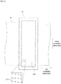
- FIG. 3 is a view conceptually illustrating the relationship among the transparent base material 9, a process-color image Ip, and a non process-color image Iw.
- FIG. 4 is a view of the transparent base material 9 after printing viewed from the non-print surface side (from the direction of arrow A in FIG. 3 ).
- the process-color image Ip is first printed and then the non process-color image Iw is printed on the print surface of the transparent base material 9. Therefore, as illustrated in FIG. 3 , at least part of the process-color image Ip is covered with the non process-color image Iw.
- a printed image I is formed on the print surface of the transparent base material 9 by the process-color image Ip and the non process-color image Iw.
- FIG. 1 is referred to again.
- the image acquisition unit 60 is disposed downstream of the second drying unit 50 in the conveyance path.
- the image acquisition unit 60 captures the printed image I at a predetermined inspection location P on the conveyance path of the transparent base material 9.
- the image acquisition unit 60 includes a first light-emitting unit 61, second light-emitting units 62, and an imaging unit 63.
- the first light-emitting unit 61 is disposed on one side (print-surface side) of the transparent base material 9.
- the second light-emitting units 62 and the imaging unit 63 are disposed on the other side (non print-surface side) of the transparent base material 9.
- the control unit 70 is a means for controlling operation of each unit in the inkjet printing apparatus 1.
- the control unit 70 of the present embodiment is configured by a computer including a processor 71 such as a CPU, a memory 72 such as a RAM, and a storage unit 73 such as a hard disk drive.
- the control unit 70 is communicably connected to the conveyance mechanism 10, the four heads 21 of the first printing unit 20, the first drying unit 30, the head 41 of the second printing unit 40, the second drying unit 50, the first light-emitting unit 61, the second light-emitting units 62, and the imaging unit 63 described above.
- the control unit 70 temporarily reads a computer program CP stored in the storage unit 73 into the memory 72, and the processor 71 performs arithmetic processing based on the computer program CP to control operation of each unit described above.
- the printing process in the inkjet printing apparatus 1 and an inspection process to be described below advance.
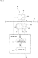
- FIG. 5 is a diagram illustrating a configuration of the image acquisition unit 60.
- the image acquisition unit 60 of the present embodiment includes the first light-emitting unit 61, the second light-emitting units 62, and the imaging unit 63.
- the first light-emitting unit 61 is located on one side (print-surface side) of the transparent base material 9 at the inspection location P.
- the first light-emitting unit 61 includes a plurality of light sources 610 arranged in the main scanning direction.
- As the light source 610 for example, an LED (Light Emitting Diode) is used.
- each light source 610 of the first light-emitting unit 61 emits light.
- Light emitted from the first light-emitting unit 61 is preferably white light.
- the second light-emitting units 62 are located on the other side (non print-surface side) of the transparent base material 9 at the inspection location P.
- the second light-emitting units 62 are provided on the upstream side and the downstream side of the imaging unit 63, respectively.
- the second light-emitting units 62 may be installed only on either the upstream side or the downstream side of the imaging unit 63.
- the second light-emitting unit 62 includes a plurality of light sources 620 arranged in the main scanning direction.
- the light source 620 for example, an LED (Light Emitting Diode) is used.
- each light source 620 of the second light-emitting unit 62 emits light. As a result, light is emitted from the second light-emitting unit 62 toward the transparent base material 9. Light emitted from the second light-emitting unit 62 is preferably white light.
- the light amounts of emitted light from the first light-emitting unit 61 and the second light-emitting unit 62 of the present embodiment can be individually changed.
- the light amount is set, for example, by the user inputting a desired value to the control unit 70.
- the imaging unit 63 is located on the other side (non print-surface side) of the transparent base material 9 at the inspection location P. That is, the first light-emitting unit 61 and the imaging unit 63 are located on the opposite sides of the transparent base material 9 with the inspection location P interposed therebetween.
- the imaging unit 63 includes a plurality of imaging elements 630 arranged in the main scanning direction.
- As the imaging element 630 for example, a CCD (Charge-Coupled Device) or a CMOS (Complementary MOS) is used.
- the imaging unit 63 images the transparent base material 9 passing through the inspection location P by using these imaging elements 630. As a result, the image of the transparent base material 9 passing through the inspection location P is obtained as multi-tone digital data.
- an image obtained by the imaging unit 63 is referred to as a "captured image D1".
- the captured image D1 is output from the imaging unit 63 to the control unit 70.
- the control unit 70 includes an inspection processing unit 74.
- the inspection processing unit 74 is a processing unit for inspecting the quality of the printed image I printed on the transparent base material 9 based on the captured image D1 obtained from the imaging unit 63.
- the function of the inspection processing unit 74 is realized by the computer as the control unit 70 operating according to the computer program CP described above.
- the first light-emitting unit 61, the second light-emitting units 62, the imaging unit 63, and the inspection processing unit 74 constitute an inspection device that inspects the printed image I printed on the surface of the transparent base material 9.
- a normal image D2 is stored in advance in the storage unit 73 of the control unit 70.
- the normal image D2 is an image illustrating a state in which the transparent base material 9 is normally printed.
- the normal image D2 is generated in the control unit 70 based on print data.
- the inspection processing unit 74 acquires the captured image D1 from the imaging unit 63 and reads the normal image D2 from the storage unit 73. Then, the captured image D1 and the normal image D2 are compared. As a result, a portion in which the difference between the captured image D1 and the normal image D2 is greater than a preset threshold is detected as a defect.
- Examples of the types of defects include missing of a portion of the printed image I due to clogging of some of the nozzles or the like, misalignment of the printed image I on the print surface of the transparent base material 9, dirt due to unnecessary dropping of ink from the nozzle, and adhesion of foreign matter to the transparent base material 9. Whether or not a character or a code included in the printed image I can be normally identified may also be set as one of the inspection items.
- the normal image D2 used is an image generated based on the print data; however, the normal image D2 is not limited to this.
- a normal image D2 may be generated from an average image of a plurality of captured images D1, or the like. In this case, it is necessary to confirm that an identical defect does not occur in identical spots; however as compared with a case where the normal image D2 is generated based on the print data, it is possible to suppress the labor of color conversion and resolution conversion and to reduce errors caused by processes of color conversion and resolution conversion.
- the inkjet printing apparatus 1 repeatedly executes steps S1 to S3 in FIG. 6 while executing the printing process on the transparent base material 9.
- the image acquisition unit 60 images the transparent base material 9 passing through the inspection location P (step SI). Specifically, the imaging unit 63 images the transparent base material 9 at the inspection location P while light is emitted toward the transparent base material 9 from the first light-emitting unit 61 and the second light-emitting units 62 described above. As a result, the captured image D1 of the transparent base material 9 at the inspection location P is obtained.
- the first light-emitting unit 61 emits light from one side of the transparent base material 9, and the light is incident on the imaging unit 63 located on the other side of the transparent base material 9. That is, the imaging unit 63 receives light emitted from the back of the transparent base material 9. Accordingly, it is possible to suppress generation of the shadow of the printed image I itself in the vicinity of the printed image I by emitted light from the second light-emitting units 62. Therefore, the imaging unit 63 can obtain a clear captured image D1 in which shadow is suppressed. The captured image D1 obtained is output from the imaging unit 63 to the control unit 70.
- the inspection processing unit 74 in the control unit 70 compares the captured image D1 with the normal image D2 read from the storage unit 73. Then, it is judged whether or not there is a defective portion having a large difference from the normal image D2 in the captured image D1 (step S2). As a result, the quality of the printed image I formed on the print surface of the transparent base material 9 is inspected. Specifically, it is judged for each pixel whether or not the difference in pixel value between the captured image D1 and the normal image D2 exceeds a preset threshold value, and the pixel with the difference exceeding the threshold value is set as a defective portion.
- control unit 70 outputs the inspection result obtained by the inspection processing unit 74 (step S3).
- the inspection result is displayed on a display connected to the control unit 70.
- the user of the inkjet printing apparatus 1 can recognize a defect included in the printed image I by checking the inspection result displayed on the display.
- the control unit 70 does not necessarily have to display the inspection result.
- the control unit 70 may sequentially accumulate the inspection results in a specific storage area in the storage unit 73.
- step S1 of the present embodiment the captured image D1 in which generation of the shadow of the printed image I itself is suppressed is obtained by emitting light from the first light-emitting unit 61. Therefore, in step S2 of the present embodiment, the defect in the printed image I can be accurately inspected based on the obtained captured image D1.
- step S1 of the present embodiment not only the first light-emitting unit 61 located on one side of the transparent base material 9 but also the second light-emitting units 62 located on the other side of the transparent base material 9 emit light. As a result, sufficient light is emitted also to the portion of the process-color image Ip covered with the non process-color image Iw. Therefore, the imaging unit 63 can image the entire printed image I more clearly. Therefore, in step S2 of the present embodiment, the defect in the printed image I can be inspected more accurately based on the obtained captured image D1.
- the light amounts of emitted light from the first light-emitting unit 61 and the second light-emitting unit 62 of the present embodiment can be individually changed. Therefore, the light amounts of the first light-emitting unit 61 and the second light-emitting unit 62 and the balance of the light amounts can be adjusted as desired. As a result, it is possible to prevent a problem such as so-called lens flare due to an inappropriate amount of light from occurring in the captured image D1. Particularly, in a case where the area ratio of the non process-color image Iw is small, lens flare is likely to occur due to emitted light from the first light-emitting unit 61.
- control unit 70 may automatically reduce the light amount of the first light-emitting unit 61 more as the area ratio of the non process-color image Iw in the printed image I is smaller. Note that the light amount of only one of the first light-emitting unit 61 and the second light-emitting units 62 may be able to be changed.
- FIG. 7 is a diagram illustrating a configuration of an image acquisition unit 60 according to the second embodiment.
- the image acquisition unit 60 of the present embodiment includes a first light-emitting unit 61, second light-emitting units 62, an imaging unit 63, and a background plate 64.
- the background plate 64 is located on one side (print-surface side) of a transparent base material 9 at an inspection location P.
- the background plate 64 has a background surface 640 that extends in parallel to the print surface of the transparent base material 9 and faces the print surface.
- the background surface 640 covers the entire width of the transparent base material 9 in the main scanning direction.
- the color of the background surface 640 of the background plate 64 is a color different from any of the colors of inks ejected from heads 21 of a first printing unit 20 (process colors) and the color of ink ejected from a head 41 of a second printing unit 40 (non-process color).
- the color of the background plate 64 is gray.
- the first light-emitting unit 61 is disposed on one side (print-surface side) of the transparent base material 9.
- the emission direction of light from the first light-emitting unit 61 of the present embodiment is directed not to the transparent base material 9 but to the background plate 64.
- the first light-emitting unit 61 includes a plurality of light sources 610 arranged in the main scanning direction.
- As the light source 610 for example, an LED (Light Emitting Diode) is used.
- a drive current is supplied to the first light-emitting unit 61 according to a command from the control unit 70, each light source 610 of the first light-emitting unit 61 emits light.
- Light emitted from the first light-emitting unit 61 is preferably white light.
- Second light-emitting units 62, an imaging unit 63, and an inspection processing unit 74 are equal to those in the above-described first embodiment, and thus overlapping description will be omitted.
- the first light-emitting unit 61, the second light-emitting units 62, the imaging unit 63, the background plate 64, and the inspection processing unit 74 constitute an inspection device that inspects a printed image I printed on the surface of the transparent base material 9.
- step S1 imaging is performed with the background plate 64 disposed on one side of the transparent base material 9.
- the first light-emitting unit 61 emits light not to the transparent base material 9 but to the background plate 64.
- light reflected by the background surface 640 of the background plate 64 passes through the transparent base material 9 and is incident on the imaging unit 63.
- step S1 it is possible to acquire a captured image D1 in which the shadow of the printed image I itself is suppressed by light emitted from the first light-emitting unit 61 and reflected by the background plate 64. Therefore, in step S2 of the present embodiment, the defect in the printed image I can be accurately inspected based on the obtained captured image D1.
- the captured image D1 obtained in step S1 includes a portion corresponding to the background surface 640 of the background plate 64 and a portion corresponding to the printed image I located in front of the background surface 640.
- the color of the background plate 64 is a color different from any of the colors of inks ejected from the heads 21 of the first printing unit 20 (process colors) and the color of ink ejected from the head 41 of the second printing unit 40 (non-process color). Therefore, in the obtained captured image D1, a process-color image Ip and a non process-color image Iw appear clearly distinguishably from the background surface 640. Therefore, the printed image I can be accurately inspected based on the captured image D1.
- the color of the background surface 640 of the background plate 64 may be a color corresponding to a multi-primary color including two or more color components of the plurality of process colors and the non-process color.
- a background color is gray
- FIG. 8 is a flowchart illustrating an example of a background color determination method.
- a plurality of candidate colors that are candidates for the background color are prepared.
- Each candidate color is a multi-primary color including two or more color components of the plurality of process colors and the non-process color.
- the plurality of process colors, the non-process color, and the plurality of candidate colors are printed on the transparent base material 9 (step S11).
- the process colors, the non-process color, and the plurality of candidate colors that are printed are imaged by the imaging unit 63 (step S12).
- the captured image obtained by the imaging unit 63 is data defined not by CMYK but by RGB. That is, the colors in the captured image are represented by combinations of R (red), G (green), and B (blue) values.
- the RGB values of the plurality of process colors and the non-process color are compared with the RGB values of each candidate color (step S13). Then, the candidate color with largest difference in RGB value from the plurality of process colors and the non-process color is determined as the background color (step S14).
- the background surface 640 of the background plate 64 and the printed image I can be more clearly distinguished in the captured image D1. Therefore, the printed image I can be accurately inspected based on the captured image D1.
- FIG. 9 is a diagram illustrating a configuration of an image acquisition unit 60 according to a third embodiment.
- an image acquisition unit 60 of the present embodiment is different from the second embodiment in that the image acquisition unit 60 includes a projection unit 65 in lieu of the first light-emitting unit 61. That is, the image acquisition unit 60 of the present embodiment includes second light-emitting units 62, an imaging unit 63, a background plate 64, and the projection unit 65.
- the color of a background surface 640 of the background plate 64 in the present embodiment is white.
- the projection unit 65 is located on one side (print-surface side) of a transparent base material 9.
- the projection unit 65 is directed to the background surface 640 of the background plate 64.
- the projection unit 65 includes a plurality of rows of light sources 650 arranged in the main scanning direction.
- the light sources 650 in each row emit different colors.
- As the light source 650 for example, an LED (Light Emitting Diode) is used.
- the projection unit 65 causes the light sources 650 in any row to emit light in response to a command from the control unit 70. As a result, light in a plurality of colors is selectively emitted from the projection unit 65 toward the background surface 640 of the background plate 64.
- the second light-emitting units 62, the imaging unit 63, and an inspection processing unit 74 are equal to those in the above-described first and second embodiments, and thus overlapping description will be omitted.
- the second light-emitting units 62, the imaging unit 63, the background plate 64, the projection unit 65, and the inspection processing unit 74 constitute an inspection device that inspects a printed image I printed on the surface of the transparent base material 9.
- step S1 imaging is performed with the background plate 64 disposed on one side of the transparent base material 9.
- the projection unit 65 emits light in a predetermined color to the background plate 64.
- light reflected by the background surface 640 of the background plate 64 passes through the transparent base material 9 and is incident on the imaging unit 63.
- step S1 it is possible to acquire a captured image D1 in which the shadow of the printed image I itself is suppressed by light emitted from the projection unit 65 and reflected by the background plate 64. Therefore, in step S2 of the present embodiment, the defect in the printed image I can be accurately inspected based on the obtained captured image D1.
- the captured image D1 obtained in step S1 includes a portion corresponding to the background surface 640 of the background plate 64 and a portion corresponding to the printed image I located in front of the background surface 640.
- the color of the light emitted from the projection unit 65 to the background plate 64 is, for example, a color different from any of the colors of inks ejected from heads 21 of a first printing unit 20 (process colors) and the color of ink ejected from a head 41 of a second printing unit 40 (non-process color). Therefore, in the obtained captured image D1, a process-color image Ip and a non process-color image Iw, and the background surface 640 appear clearly distinguishably. Therefore, the printed image I can be accurately inspected based on the captured image D1.
- the control unit 70 switches the color of light emitted from the projection unit 65 depending on the printed image I.
- the projection unit 65 emits light in a color with the greatest difference in RGB value from the colors included in the printed image I, among the colors of light that can be emitted from the projection unit 65.
- a printed image I having a large proportion of green such as a label for a green tea beverage
- red color in contrast to green is emitted.
- blue such as a label for a sports drink
- blue such as a label for a sports drink
- the color of light emitted from the projection unit 65 may be changed for each color of the test chart.
- the printed image I and the background surface 640 can be more clearly distinguished in the captured image D1. Therefore, the printed image I can be inspected more accurately based on the captured image D1.
- the second light-emitting units 62 may be omitted in the configuration of the image acquisition unit 60 of the first embodiment.
- the first light-emitting unit 61 may be omitted in the configuration of the image acquisition unit 60 of the second embodiment.
- the second light-emitting unit 62 may be omitted in the configuration of the image acquisition unit 60 of the second embodiment.
- the second light-emitting unit 62 may be omitted in the configuration of the image acquisition unit 60 of the third embodiment.
- light emitted from the first light-emitting unit 61 may be light other than white light.
- the color of light emitted from the first light-emitting unit 61 may be a color different from any of the colors of inks ejected from the heads 21 of the first printing unit 20 (process colors) and the color of ink ejected from the head 41 of the second printing unit 40 (non-process color).
- the color of light emitted from the first light-emitting unit 61 may be switched depending on the printed image I.
- the first printing unit 20 includes the four heads 21.
- the number of heads 21 included in the first printing unit 20 may be one to three, or may be five or more.
- heads 21 that eject inks of spot colors such as purple/violet and green in addition to inks of cyan, magenta, yellow, and black may be provided.
- an inkjet printing apparatus of the present invention may perform printing on each of a plurality of transparent base materials while sequentially conveying the plurality of transparent base materials in the sub scanning direction.
Landscapes
- Engineering & Computer Science (AREA)
- Physics & Mathematics (AREA)
- Spectroscopy & Molecular Physics (AREA)
- General Physics & Mathematics (AREA)
- Multimedia (AREA)
- Signal Processing (AREA)
- Quality & Reliability (AREA)
- Textile Engineering (AREA)
- General Engineering & Computer Science (AREA)
- Theoretical Computer Science (AREA)
- Ink Jet (AREA)
- Investigating Materials By The Use Of Optical Means Adapted For Particular Applications (AREA)
Abstract
Description
- The present invention relates to an inspection device that inspects a printed image printed on a surface of a transparent base material, an inkjet printing apparatus including the inspection device, and an inspection method of inspecting a printed image printed on a surface of a transparent base material.
- Conventionally, there is known an inkjet printing apparatus that prints an image on a transparent base material by ejecting an ink from a head while conveying the transparent base material. This type of inkjet printing apparatus is used, for example, in the process of manufacturing labels for beverage PET bottles and soft packaging materials. Conventional inkjet printing apparatuses that perform printing on a transparent base material are described in
Patent Literatures 1 and 2, for example. -
- Patent Literature 1:
JP 6010980 B1 - Patent Literature 2:
JP 2013-159047 A - In the process of manufacturing labels and soft packaging materials, it is required to inspect whether or not there is a defect in a printed image after the printed image is printed on a transparent base material. Examples of the types of defects include missing of a portion of a printed image due to clogging of a nozzle or the like, misalignment of a printed image with respect to a transparent base material, dirt due to unnecessary dropping of an ink from the nozzle, and adhesion of foreign matter to the transparent base material.
- When a printed image on a transparent base material is inspected, conventionally, in a state where a background plate is disposed on one side of the base material, the base material is imaged while light is emitted from the other side of the base material. Then, the defect is detected by comparing the image obtained by imaging with a normal image. However, in this method, the shadow of the printed image itself is generated on the background plate due to light emission. Therefore, it is necessary to suppress sensitivity of the inspection so as to prevent the shadow from being erroneously detected. Therefore, it is difficult to accurately inspect a printed image printed on a surface of a transparent base material.
- Furthermore, conventionally, the color of the background plate is white. However, in printing on a transparent base material, there are cases where not only so-called process color inks such as cyan, magenta, yellow, and black and so-called spot-color inks such as purple/violet and green, but also a white ink are used. In a conventional inspection, it is difficult to accurately distinguish the white background plate and an image formed by the white ink. Therefore, it is difficult to accurately inspect a printed image printed on a surface of a transparent base material.
- The present invention has been made in view of these circumstances, and an object of the present invention is to provide an inspection device, an inkjet printing apparatus, and an inspection method capable of accurately inspecting a printed image printed on a surface of a transparent base material.
- A first invention of the present application is an inspection device that inspects a printed image printed on a surface of a transparent base material, the device including a first light-emitting unit configured to emit light from one side of the transparent base material toward the transparent base material, an imaging unit configured to image the transparent base material from another side of the transparent base material, and an inspection processing unit configured to inspect quality of the printed image based on a captured image obtained by the imaging unit.
- A second invention of the present application is the inspection device according to the first invention, in which the printed image includes a process-color image that is formed by inks of a plurality of process colors, and a non process-color image that is formed by an ink of a non-process color different from the plurality of process colors and that covers the one side of the process-color image, the inspection device further including a second light-emitting unit configured to emit light from the other side of the transparent base material toward the transparent base material.
- A third invention of the present application is the inspection device of the second invention, in which a light amount of at least one of the first light-emitting unit and the second light-emitting unit is capable of being changed.
- A fourth invention of the present application is the inspection device of the third invention, the device further including a control unit configured to reduce the light amount of the first light-emitting unit more as an area ratio of the non process-color image is smaller.
- A fifth invention of the present application is the inspection device according to any one of the second invention to the fourth invention, in which the plurality of process colors include cyan, magenta, yellow, and black, and the non-process color is white.
- A sixth invention of the present application is an inspection device that inspects a printed image printed on a surface of a transparent base material, the printed image including a process-color image that is formed by inks of a plurality of process colors, and a non process-color image that is formed by an ink of a non-process color different from the plurality of process colors and that covers the process-color image, the inspection device including a background plate disposed on one side of the transparent base material, an imaging unit configured to image the transparent base material from another side of the transparent base material, and an inspection processing unit configured to inspect quality of the printed image based on a captured image obtained by the imaging unit, in which the color of the background plate is a color different from any of the plurality of process colors and the non-process color.
- A seventh invention of the present application is the inspection device of the sixth invention, in which the color of the background plate is a multi-primary color including two or more color components of the plurality of process colors and the non-process color.
- An eighth invention of the present application is the inspection device of the sixth invention or the seventh invention, the device further including a light-emitting unit configured to emit light toward a surface of the background plate on a transparent base material side.
- A ninth invention of the present application is the inspection device according to any one of the sixth invention to the eighth invention, in which the plurality of process colors include cyan, magenta, yellow, and black, and the non-process color is white.
- A tenth invention of the present application is an inspection device that inspects a printed image printed on a surface of a transparent base material, the device including a background plate disposed on one side of the transparent material, a projection unit configured to emit projected light in a plurality of colors on a surface of the background plate on a transparent base material side while switching the projected light, an imaging unit configured to image the transparent base material from another side of the transparent base material, and an inspection processing unit configured to inspect quality of the printed image based on a captured image obtained by the imaging unit.
- An eleventh invention of the present application is an inkjet printing apparatus including the inspection device of any one of the first invention to the tenth invention, the apparatus including a conveyance mechanism configured to convey a transparent base material along a predetermined conveyance path, and a printing unit configured to perform printing by an inkjet method on a surface of the transparent base material that is conveyed by the conveyance mechanism, in which the light-emitting unit and the imaging unit are located downstream of the printing unit in the conveyance path.
- A twelfth invention of the present application is an inspection method of inspecting a printed image printed on a surface of a transparent base material, the method including a) a process of, while emitting light from one side of the transparent base material toward the transparent base material, imaging the transparent base material from another side of the transparent base material, and b) a process of inspecting quality of the printed image based on a captured image obtained in the process a).
- A thirteenth invention of the present application is an inspection method of inspecting a printed image printed on a surface of a transparent base material, the printed image including a process-color image that is formed by inks of a plurality of process colors, and a non process-color image that is formed by an ink of a non-process color different from the plurality of process colors and that covers the process-color image, the inspection method including a) a process of, in a state where a background plate is disposed on one side of a transparent base material, imaging the transparent base material from another side of the transparent base material, and b) a process of inspecting quality of the printed image based on a captured image obtained in the process a), in which the color of the background plate is a color different from any of the plurality of process colors and the non-process color.
- A fourteenth invention of the present application is an inspection method of inspecting a printed image printed on a surface of a transparent base material, the method including a) a process of, in a state where a background plate is disposed on one side of a transparent base material, imaging the transparent base material from another side of the transparent base material, and b) a process of inspecting quality of the printed image based on a captured image obtained in the process a), in which in the process a), projected light in different colors depending on the printed image is emitted on a surface of the background plate on a transparent base material side. Advantageous Effects of Invention
- According to the first to fifth inventions of the present application, the first light-emitting unit and the imaging unit are disposed on opposite sides of the transparent base material. As a result, it is possible to suppress generation of the shadow of the printed image itself in the captured image. Therefore, the printed image can be accurately inspected based on the obtained captured image.
- Particularly, according to the second invention of the present application, the process-color image covered with the non process-color image can be satisfactorily imaged with emitted light from the second light-emitting unit.
- According to the sixth invention to the ninth invention of the present application, in the captured image, the process-color image and the non process-color image appear clearly and distinguishably from the background plate. Therefore, the printed image can be accurately inspected based on the obtained captured image.
- According to the tenth invention of the present application, it is possible to switch the color of the projected light emitted to the background plate depending on the printed image. As a result, the printed image appears satisfactorily in the captured image. Therefore, the printed image can be accurately inspected based on the obtained captured image.
- According to the eleventh invention of the present application, an inspection after printing can be accurately performed in the inkjet printing apparatus that performs printing on a transparent base material.
- According to the twelfth invention of the present application, while light is emitted from one side of the transparent base material, the transparent base material is imaged from the other side of the transparent base material. As a result, it is possible to suppress generation of the shadow of the printed image itself in the captured image. Therefore, the printed image can be accurately inspected based on the obtained captured image.
- According to the thirteenth invention of the present application, in the captured image, the process-color image and the non process-color image appear clearly and distinguishably from the background plate. Therefore, the printed image can be accurately inspected based on the obtained captured image.
- According to the fourteenth invention of the present application, projected light in different colors depending on the printed image is emitted on the surface of the background plate on the transparent base material side. As a result, the printed image appears satisfactorily in the captured image. Therefore, the printed image can be accurately inspected based on the obtained captured image.
-
-
FIG. 1 is a diagram illustrating a configuration of an inkjet printing apparatus. -
FIG. 2 is a bottom view of a head. -
FIG. 3 is a view conceptually illustrating the relationship among a transparent base material, a process-color image, and a non process-color image. -
FIG. 4 is a view of the transparent base material after printing as viewed from the non-print surface side. -
FIG. 5 is a diagram illustrating a configuration of an image acquisition unit. -
FIG. 6 is a flowchart illustrating a procedure for inspecting a printed image. -
FIG. 7 is a diagram illustrating a configuration of an image acquisition unit according to a second embodiment. -
FIG. 8 is a flowchart illustrating an example of a background color determination method. -
FIG. 9 is a diagram illustrating a configuration of an image acquisition unit according to a third embodiment. - Hereinafter, embodiments of the present invention will be described with reference to the drawings. Note that, below, the direction orthogonal to the conveyance direction of a transparent base material and along the surface of the transparent base material is referred to as a "main scanning direction". Furthermore, the conveyance direction of the transparent base material is referred to as a "sub scanning direction".
-
FIG. 1 is a diagram illustrating a configuration of aninkjet printing apparatus 1 according to a first embodiment of the present invention. Theinkjet printing apparatus 1 is an apparatus that prints a multicolor image on a surface of thetransparent base material 9 having a long band shape by an inkjet method while conveying thetransparent base material 9. As thetransparent base material 9, for example, a colorless and transparent resin film is used. Thetransparent base material 9 after printing is cut into a label for a beverage PET bottle, for example. - As illustrated in
FIG. 1 , theinkjet printing apparatus 1 includes aconveyance mechanism 10, afirst printing unit 20, afirst drying unit 30, asecond printing unit 40, asecond drying unit 50, animage acquisition unit 60, and acontrol unit 70. - The
conveyance mechanism 10 is a mechanism that conveys thetransparent base material 9 in the sub scanning direction, which is the longitudinal direction thereof. Theconveyance mechanism 10 according to the present embodiment includes an unwindingunit 11, a plurality ofconveyance rollers 12, and a windingunit 13. Thetransparent base material 9 is unwound from the unwindingunit 11 and is conveyed along a conveyance path configured by a plurality ofconveyance rollers 12. Eachconveyance roller 12 rotates about a horizontal axis to guide thetransparent base material 9 to the downstream side of the conveyance path. Furthermore, thetransparent base material 9 after having been conveyed is collected by the windingunit 13. - As illustrated in
FIG. 1 , thetransparent base material 9 moves substantially horizontally at the location under thefirst printing unit 20 and thesecond printing unit 40. At this time, the print surface of thetransparent base material 9 is faced up. Thetransparent base material 9 is stretched over the plurality ofconveyance rollers 12 in a tensioned state. As a result, loosening and a wrinkle of thetransparent base material 9 during conveyance are suppressed. - The
first printing unit 20 is a processing unit that ejects so-called process color inks onto thetransparent base material 9 conveyed by theconveyance mechanism 10. Thefirst printing unit 20 of the present embodiment includes four heads 21. Theheads 21 eject ink droplets of cyan, magenta, yellow, and black, which are process colors, onto the print surface of thetransparent base material 9, respectively. Eachhead 21 is fixed to a housing (not illustrated) of theinkjet printing apparatus 1. -
FIG. 2 is a bottom view of thehead 21. As illustrated inFIG. 2 , anejection surface 210 for ejecting ink droplets is provided on a lower part of thehead 21. Theejection surface 210 covers the entire width of thetransparent base material 9 in the main scanning direction. As illustrated in an enlarged manner inFIG. 2 , a plurality ofnozzles 211 are regularly arranged on theejection surface 210. The plurality ofnozzles 211 is arranged so that their positions in the main scanning direction are different from each other. - At the time of printing, ink droplets are ejected from the plurality of
nozzles 211 of eachhead 21 toward the print surface of thetransparent base material 9. That is, ink droplets of cyan, magenta, yellow, and black, which are process colors, are ejected from the plurality ofnozzles 211 of theheads 21, respectively. As a result, the fourheads 21 print single-color images of cyan, magenta, yellow, and black on the print surface of thetransparent base material 9, respectively. Then, a multicolor image is formed on the print surface of thetransparent base material 9 by superposing these four single-color images. Hereinafter, the multicolor image printed by thefirst printing unit 20 is referred to as a "process-color image". - The
first drying unit 30 is disposed on the downstream side of thefirst printing unit 20 in the conveyance path. Thefirst drying unit 30 dries the process color inks ejected from the fourheads 21 of thefirst printing unit 20. As a result, the process color inks are fixed on the print surface of thetransparent base material 9. For example, thefirst drying unit 30 dries the inks by blowing hot air toward thetransparent base material 9 to vaporize a solvent in the inks that adheres to thetransparent base material 9. However, thefirst drying unit 30 may dry or cure the inks by another method such as light emission. - The
second printing unit 40 is disposed downstream of thefirst drying unit 30 in the conveyance path. Thesecond printing unit 40 is a processing unit that ejects an ink of a non-process color different from cyan, magenta, yellow, and black described above onto thetransparent base material 9 conveyed by theconveyance mechanism 10. Thesecond printing unit 40 of the present embodiment includes onehead 41 that ejects ink droplets of white, which is a non-process color. Thehead 41 is fixed to a housing (not illustrated) of theinkjet printing apparatus 1. - The
head 41 of thesecond printing unit 40 also includes a plurality of nozzles, similarly to thehead 21 of thefirst printing unit 20 described above. Thehead 41 ejects white ink droplets from a plurality of nozzles toward the print surface of thetransparent base material 9. As a result, a white single-color image is printed on the print surface of thetransparent base material 9. Hereinafter, a white single-color image printed by thesecond printing unit 40 is referred to as a "non process-color image". - The
second drying unit 50 is disposed downstream of thesecond printing unit 40 in the conveyance path. Thesecond drying unit 50 dries the non process-color ink ejected from thehead 41 of thesecond printing unit 40. As a result, the non process-color ink is fixed on the print surface of thetransparent base material 9. For example, thesecond drying unit 50 dries the ink by blowing heated gas toward thetransparent base material 9 to vaporize a solvent in the ink that adheres to thetransparent base material 9. However, thesecond drying unit 50 may dry or cure the ink by another method such as light emission. -
FIG. 3 is a view conceptually illustrating the relationship among thetransparent base material 9, a process-color image Ip, and a non process-color image Iw.FIG. 4 is a view of thetransparent base material 9 after printing viewed from the non-print surface side (from the direction of arrow A inFIG. 3 ). As described above, in theinkjet printing apparatus 1 of the present embodiment, the process-color image Ip is first printed and then the non process-color image Iw is printed on the print surface of thetransparent base material 9. Therefore, as illustrated inFIG. 3 , at least part of the process-color image Ip is covered with the non process-color image Iw. A printed image I is formed on the print surface of thetransparent base material 9 by the process-color image Ip and the non process-color image Iw. -
FIG. 1 is referred to again. Theimage acquisition unit 60 is disposed downstream of thesecond drying unit 50 in the conveyance path. Theimage acquisition unit 60 captures the printed image I at a predetermined inspection location P on the conveyance path of thetransparent base material 9. As illustrated inFIG. 1 , theimage acquisition unit 60 includes a first light-emittingunit 61, second light-emittingunits 62, and animaging unit 63. The first light-emittingunit 61 is disposed on one side (print-surface side) of thetransparent base material 9. The second light-emittingunits 62 and theimaging unit 63 are disposed on the other side (non print-surface side) of thetransparent base material 9. - Details of the
image acquisition unit 60 will be described later. - The
control unit 70 is a means for controlling operation of each unit in theinkjet printing apparatus 1. Thecontrol unit 70 of the present embodiment is configured by a computer including aprocessor 71 such as a CPU, amemory 72 such as a RAM, and astorage unit 73 such as a hard disk drive. As indicated by broken lines inFIG. 1 , thecontrol unit 70 is communicably connected to theconveyance mechanism 10, the fourheads 21 of thefirst printing unit 20, thefirst drying unit 30, thehead 41 of thesecond printing unit 40, thesecond drying unit 50, the first light-emittingunit 61, the second light-emittingunits 62, and theimaging unit 63 described above. Thecontrol unit 70 temporarily reads a computer program CP stored in thestorage unit 73 into thememory 72, and theprocessor 71 performs arithmetic processing based on the computer program CP to control operation of each unit described above. As a result, the printing process in theinkjet printing apparatus 1 and an inspection process to be described below advance. - Subsequently, details of the
image acquisition unit 60 will be described later.FIG. 5 is a diagram illustrating a configuration of theimage acquisition unit 60. As described above, theimage acquisition unit 60 of the present embodiment includes the first light-emittingunit 61, the second light-emittingunits 62, and theimaging unit 63. - The first light-emitting
unit 61 is located on one side (print-surface side) of thetransparent base material 9 at the inspection location P. The first light-emittingunit 61 includes a plurality oflight sources 610 arranged in the main scanning direction. As thelight source 610, for example, an LED (Light Emitting Diode) is used. When a drive current is supplied to the first light-emittingunit 61 according to a command from thecontrol unit 70, eachlight source 610 of the first light-emittingunit 61 emits light. As a result, light is emitted from the first light-emittingunit 61 toward thetransparent base material 9. Light emitted from the first light-emittingunit 61 is preferably white light. - The second light-emitting
units 62 are located on the other side (non print-surface side) of thetransparent base material 9 at the inspection location P. In the present embodiment, the second light-emittingunits 62 are provided on the upstream side and the downstream side of theimaging unit 63, respectively. However, the second light-emittingunits 62 may be installed only on either the upstream side or the downstream side of theimaging unit 63. The second light-emittingunit 62 includes a plurality oflight sources 620 arranged in the main scanning direction. As thelight source 620, for example, an LED (Light Emitting Diode) is used. When a drive current is supplied to the second light-emittingunit 62 according to a command from thecontrol unit 70, eachlight source 620 of the second light-emittingunit 62 emits light. As a result, light is emitted from the second light-emittingunit 62 toward thetransparent base material 9. Light emitted from the second light-emittingunit 62 is preferably white light. - The light amounts of emitted light from the first light-emitting
unit 61 and the second light-emittingunit 62 of the present embodiment can be individually changed. The light amount is set, for example, by the user inputting a desired value to thecontrol unit 70. - The
imaging unit 63 is located on the other side (non print-surface side) of thetransparent base material 9 at the inspection location P. That is, the first light-emittingunit 61 and theimaging unit 63 are located on the opposite sides of thetransparent base material 9 with the inspection location P interposed therebetween. Theimaging unit 63 includes a plurality ofimaging elements 630 arranged in the main scanning direction. As theimaging element 630, for example, a CCD (Charge-Coupled Device) or a CMOS (Complementary MOS) is used. Theimaging unit 63 images thetransparent base material 9 passing through the inspection location P by using theseimaging elements 630. As a result, the image of thetransparent base material 9 passing through the inspection location P is obtained as multi-tone digital data. Hereinafter, an image obtained by theimaging unit 63 is referred to as a "captured image D1". The captured image D1 is output from theimaging unit 63 to thecontrol unit 70. - Furthermore, as conceptually illustrated in
FIG. 5 , thecontrol unit 70 includes aninspection processing unit 74. Theinspection processing unit 74 is a processing unit for inspecting the quality of the printed image I printed on thetransparent base material 9 based on the captured image D1 obtained from theimaging unit 63. The function of theinspection processing unit 74 is realized by the computer as thecontrol unit 70 operating according to the computer program CP described above. In the present embodiment, the first light-emittingunit 61, the second light-emittingunits 62, theimaging unit 63, and theinspection processing unit 74 constitute an inspection device that inspects the printed image I printed on the surface of thetransparent base material 9. - A normal image D2 is stored in advance in the
storage unit 73 of thecontrol unit 70. The normal image D2 is an image illustrating a state in which thetransparent base material 9 is normally printed. The normal image D2 is generated in thecontrol unit 70 based on print data. Theinspection processing unit 74 acquires the captured image D1 from theimaging unit 63 and reads the normal image D2 from thestorage unit 73. Then, the captured image D1 and the normal image D2 are compared. As a result, a portion in which the difference between the captured image D1 and the normal image D2 is greater than a preset threshold is detected as a defect. - Examples of the types of defects include missing of a portion of the printed image I due to clogging of some of the nozzles or the like, misalignment of the printed image I on the print surface of the
transparent base material 9, dirt due to unnecessary dropping of ink from the nozzle, and adhesion of foreign matter to thetransparent base material 9. Whether or not a character or a code included in the printed image I can be normally identified may also be set as one of the inspection items. - Furthermore, in the present embodiment, the normal image D2 used is an image generated based on the print data; however, the normal image D2 is not limited to this. For example, in a case where an identical image is repeatedly printed, a normal image D2 may be generated from an average image of a plurality of captured images D1, or the like. In this case, it is necessary to confirm that an identical defect does not occur in identical spots; however as compared with a case where the normal image D2 is generated based on the print data, it is possible to suppress the labor of color conversion and resolution conversion and to reduce errors caused by processes of color conversion and resolution conversion.
- Subsequently, the inspection procedure of the printed image I in the
inkjet printing apparatus 1 will be described with reference to the flowchart ofFIG. 6 . Theinkjet printing apparatus 1 repeatedly executes steps S1 to S3 inFIG. 6 while executing the printing process on thetransparent base material 9. - First, the
image acquisition unit 60 images thetransparent base material 9 passing through the inspection location P (step SI). Specifically, theimaging unit 63 images thetransparent base material 9 at the inspection location P while light is emitted toward thetransparent base material 9 from the first light-emittingunit 61 and the second light-emittingunits 62 described above. As a result, the captured image D1 of thetransparent base material 9 at the inspection location P is obtained. - At this time, the first light-emitting
unit 61 emits light from one side of thetransparent base material 9, and the light is incident on theimaging unit 63 located on the other side of thetransparent base material 9. That is, theimaging unit 63 receives light emitted from the back of thetransparent base material 9. Accordingly, it is possible to suppress generation of the shadow of the printed image I itself in the vicinity of the printed image I by emitted light from the second light-emittingunits 62. Therefore, theimaging unit 63 can obtain a clear captured image D1 in which shadow is suppressed. The captured image D1 obtained is output from theimaging unit 63 to thecontrol unit 70. - When the captured image D1 is input to the
control unit 70, theinspection processing unit 74 in thecontrol unit 70 compares the captured image D1 with the normal image D2 read from thestorage unit 73. Then, it is judged whether or not there is a defective portion having a large difference from the normal image D2 in the captured image D1 (step S2). As a result, the quality of the printed image I formed on the print surface of thetransparent base material 9 is inspected. Specifically, it is judged for each pixel whether or not the difference in pixel value between the captured image D1 and the normal image D2 exceeds a preset threshold value, and the pixel with the difference exceeding the threshold value is set as a defective portion. - Thereafter, the
control unit 70 outputs the inspection result obtained by the inspection processing unit 74 (step S3). For example, the inspection result is displayed on a display connected to thecontrol unit 70. The user of theinkjet printing apparatus 1 can recognize a defect included in the printed image I by checking the inspection result displayed on the display. However, thecontrol unit 70 does not necessarily have to display the inspection result. Thecontrol unit 70 may sequentially accumulate the inspection results in a specific storage area in thestorage unit 73. - As described above, in step S1 of the present embodiment, the captured image D1 in which generation of the shadow of the printed image I itself is suppressed is obtained by emitting light from the first light-emitting
unit 61. Therefore, in step S2 of the present embodiment, the defect in the printed image I can be accurately inspected based on the obtained captured image D1. - Note that as illustrated in
FIG. 3 , in a case where a portion of the process-color image Ip is covered with the non process-color image Iw, emitted light from the first light-emittingunit 61 is blocked by the non process-color image Iw, and sufficient light is not emitted to the portion of the process-color image Ip. However, in step S1 of the present embodiment, not only the first light-emittingunit 61 located on one side of thetransparent base material 9 but also the second light-emittingunits 62 located on the other side of thetransparent base material 9 emit light. As a result, sufficient light is emitted also to the portion of the process-color image Ip covered with the non process-color image Iw. Therefore, theimaging unit 63 can image the entire printed image I more clearly. Therefore, in step S2 of the present embodiment, the defect in the printed image I can be inspected more accurately based on the obtained captured image D1. - Furthermore, the light amounts of emitted light from the first light-emitting
unit 61 and the second light-emittingunit 62 of the present embodiment can be individually changed. Therefore, the light amounts of the first light-emittingunit 61 and the second light-emittingunit 62 and the balance of the light amounts can be adjusted as desired. As a result, it is possible to prevent a problem such as so-called lens flare due to an inappropriate amount of light from occurring in the captured image D1. Particularly, in a case where the area ratio of the non process-color image Iw is small, lens flare is likely to occur due to emitted light from the first light-emittingunit 61. Therefore, thecontrol unit 70 may automatically reduce the light amount of the first light-emittingunit 61 more as the area ratio of the non process-color image Iw in the printed image I is smaller. Note that the light amount of only one of the first light-emittingunit 61 and the second light-emittingunits 62 may be able to be changed. - Subsequently, a second embodiment of the present invention will be described.
FIG. 7 is a diagram illustrating a configuration of animage acquisition unit 60 according to the second embodiment. As illustrated inFIG. 7 , theimage acquisition unit 60 of the present embodiment includes a first light-emittingunit 61, second light-emittingunits 62, animaging unit 63, and abackground plate 64. - The
background plate 64 is located on one side (print-surface side) of atransparent base material 9 at an inspection location P. Thebackground plate 64 has abackground surface 640 that extends in parallel to the print surface of thetransparent base material 9 and faces the print surface. Thebackground surface 640 covers the entire width of thetransparent base material 9 in the main scanning direction. The color of thebackground surface 640 of thebackground plate 64 is a color different from any of the colors of inks ejected fromheads 21 of a first printing unit 20 (process colors) and the color of ink ejected from ahead 41 of a second printing unit 40 (non-process color). For example, the color of thebackground plate 64 is gray. - The first light-emitting
unit 61 is disposed on one side (print-surface side) of thetransparent base material 9. The emission direction of light from the first light-emittingunit 61 of the present embodiment is directed not to thetransparent base material 9 but to thebackground plate 64. The first light-emittingunit 61 includes a plurality oflight sources 610 arranged in the main scanning direction. As thelight source 610, for example, an LED (Light Emitting Diode) is used. When a drive current is supplied to the first light-emittingunit 61 according to a command from thecontrol unit 70, eachlight source 610 of the first light-emittingunit 61 emits light. As a result, light is emitted from the first light-emittingunit 61 toward thebackground plate 64. Light emitted from the first light-emittingunit 61 is preferably white light. - Second light-emitting
units 62, animaging unit 63, and aninspection processing unit 74 are equal to those in the above-described first embodiment, and thus overlapping description will be omitted. In the present embodiment, the first light-emittingunit 61, the second light-emittingunits 62, theimaging unit 63, thebackground plate 64, and theinspection processing unit 74 constitute an inspection device that inspects a printed image I printed on the surface of thetransparent base material 9. - Also in the second embodiment, inspection of the printed image I is executed by the procedure similar to the flowchart of
FIG. 6 . However, in step S1, imaging is performed with thebackground plate 64 disposed on one side of thetransparent base material 9. The first light-emittingunit 61 emits light not to thetransparent base material 9 but to thebackground plate 64. Then, light reflected by thebackground surface 640 of thebackground plate 64 passes through thetransparent base material 9 and is incident on theimaging unit 63. By emitting light to thebackground plate 64 as described, generation of a shadow on thebackground plate 64 is suppressed. - That is, in the present embodiment, in step S1, it is possible to acquire a captured image D1 in which the shadow of the printed image I itself is suppressed by light emitted from the first light-emitting
unit 61 and reflected by thebackground plate 64. Therefore, in step S2 of the present embodiment, the defect in the printed image I can be accurately inspected based on the obtained captured image D1. - The captured image D1 obtained in step S1 includes a portion corresponding to the
background surface 640 of thebackground plate 64 and a portion corresponding to the printed image I located in front of thebackground surface 640. As described, the color of thebackground plate 64 is a color different from any of the colors of inks ejected from theheads 21 of the first printing unit 20 (process colors) and the color of ink ejected from thehead 41 of the second printing unit 40 (non-process color). Therefore, in the obtained captured image D1, a process-color image Ip and a non process-color image Iw appear clearly distinguishably from thebackground surface 640. Therefore, the printed image I can be accurately inspected based on the captured image D1. - The color of the
background surface 640 of the background plate 64 (hereinafter referred to as a "background color") may be a color corresponding to a multi-primary color including two or more color components of the plurality of process colors and the non-process color. For example, in a case where the background color is gray, it is preferable to use gray corresponding to a multi-primary color including color components of cyan, magenta, and yellow, rather than gray corresponding to low-density black. This is because multi-primary color is less likely to match a color used in the printed image than a single color does. -
FIG. 8 is a flowchart illustrating an example of a background color determination method. When the background color is determined, first, a plurality of candidate colors that are candidates for the background color are prepared. Each candidate color is a multi-primary color including two or more color components of the plurality of process colors and the non-process color. As illustrated inFIG. 8 , first, the plurality of process colors, the non-process color, and the plurality of candidate colors are printed on the transparent base material 9 (step S11). Next, the process colors, the non-process color, and the plurality of candidate colors that are printed are imaged by the imaging unit 63 (step S12). - Here, the captured image obtained by the
imaging unit 63 is data defined not by CMYK but by RGB. That is, the colors in the captured image are represented by combinations of R (red), G (green), and B (blue) values. After the captured image is obtained in step S12, the RGB values of the plurality of process colors and the non-process color are compared with the RGB values of each candidate color (step S13). Then, the candidate color with largest difference in RGB value from the plurality of process colors and the non-process color is determined as the background color (step S14). - By using the background color determined as described, the
background surface 640 of thebackground plate 64 and the printed image I can be more clearly distinguished in the captured image D1. Therefore, the printed image I can be accurately inspected based on the captured image D1. - Subsequently, a third embodiment of the present invention will be described.
FIG. 9 is a diagram illustrating a configuration of animage acquisition unit 60 according to a third embodiment. As illustrated inFIG. 9 , animage acquisition unit 60 of the present embodiment is different from the second embodiment in that theimage acquisition unit 60 includes aprojection unit 65 in lieu of the first light-emittingunit 61. That is, theimage acquisition unit 60 of the present embodiment includes second light-emittingunits 62, animaging unit 63, abackground plate 64, and theprojection unit 65. The color of abackground surface 640 of thebackground plate 64 in the present embodiment is white. - The
projection unit 65 is located on one side (print-surface side) of atransparent base material 9. Theprojection unit 65 is directed to thebackground surface 640 of thebackground plate 64. Theprojection unit 65 includes a plurality of rows oflight sources 650 arranged in the main scanning direction. Thelight sources 650 in each row emit different colors. As thelight source 650, for example, an LED (Light Emitting Diode) is used. Theprojection unit 65 causes thelight sources 650 in any row to emit light in response to a command from thecontrol unit 70. As a result, light in a plurality of colors is selectively emitted from theprojection unit 65 toward thebackground surface 640 of thebackground plate 64. - The second light-emitting
units 62, theimaging unit 63, and aninspection processing unit 74 are equal to those in the above-described first and second embodiments, and thus overlapping description will be omitted. In the present embodiment, the second light-emittingunits 62, theimaging unit 63, thebackground plate 64, theprojection unit 65, and theinspection processing unit 74 constitute an inspection device that inspects a printed image I printed on the surface of thetransparent base material 9. - Also in the third embodiment, inspection of the printed image I is executed by the procedure similar to the flowchart of
FIG. 6 . However, in step S1, imaging is performed with thebackground plate 64 disposed on one side of thetransparent base material 9. At this time, theprojection unit 65 emits light in a predetermined color to thebackground plate 64. Then, light reflected by thebackground surface 640 of thebackground plate 64 passes through thetransparent base material 9 and is incident on theimaging unit 63. By emitting light to thebackground plate 64 as described, generation of a shadow on thebackground plate 64 is suppressed. - That is, in the present embodiment, in step S1, it is possible to acquire a captured image D1 in which the shadow of the printed image I itself is suppressed by light emitted from the
projection unit 65 and reflected by thebackground plate 64. Therefore, in step S2 of the present embodiment, the defect in the printed image I can be accurately inspected based on the obtained captured image D1. - The captured image D1 obtained in step S1 includes a portion corresponding to the
background surface 640 of thebackground plate 64 and a portion corresponding to the printed image I located in front of thebackground surface 640. Here, the color of the light emitted from theprojection unit 65 to thebackground plate 64 is, for example, a color different from any of the colors of inks ejected fromheads 21 of a first printing unit 20 (process colors) and the color of ink ejected from ahead 41 of a second printing unit 40 (non-process color). Therefore, in the obtained captured image D1, a process-color image Ip and a non process-color image Iw, and thebackground surface 640 appear clearly distinguishably. Therefore, the printed image I can be accurately inspected based on the captured image D1. - Furthermore, in the present embodiment, the
control unit 70 switches the color of light emitted from theprojection unit 65 depending on the printed image I. Specifically, theprojection unit 65 emits light in a color with the greatest difference in RGB value from the colors included in the printed image I, among the colors of light that can be emitted from theprojection unit 65. For example, in the case of a printed image I having a large proportion of green, such as a label for a green tea beverage, light in a red color in contrast to green is emitted. Furthermore, for example, in the case of a printed image I having a large proportion of blue, such as a label for a sports drink, light in an orange color in contrast to blue is emitted. Moreover, in the case of a test chart in which a printed image I is printed for each color of cyan, magenta, yellow, black, and white for nozzle inspection, the color of light emitted from theprojection unit 65 may be changed for each color of the test chart. In this way, the printed image I and thebackground surface 640 can be more clearly distinguished in the captured image D1. Therefore, the printed image I can be inspected more accurately based on the captured image D1. - The first to third embodiments of the present invention have been described above; however, the present invention is not limited to these embodiments.
- For example, the second light-emitting
units 62 may be omitted in the configuration of theimage acquisition unit 60 of the first embodiment. Furthermore, the first light-emittingunit 61 may be omitted in the configuration of theimage acquisition unit 60 of the second embodiment. Moreover, the second light-emittingunit 62 may be omitted in the configuration of theimage acquisition unit 60 of the second embodiment. Furthermore, the second light-emittingunit 62 may be omitted in the configuration of theimage acquisition unit 60 of the third embodiment. - Furthermore, in the configuration of the
image acquisition unit 60 of the first embodiment, light emitted from the first light-emittingunit 61 may be light other than white light. For example, the color of light emitted from the first light-emittingunit 61 may be a color different from any of the colors of inks ejected from theheads 21 of the first printing unit 20 (process colors) and the color of ink ejected from thehead 41 of the second printing unit 40 (non-process color). Furthermore, the color of light emitted from the first light-emittingunit 61 may be switched depending on the printed image I. - Moreover, in the above embodiments, the
first printing unit 20 includes the four heads 21. However, the number ofheads 21 included in thefirst printing unit 20 may be one to three, or may be five or more. For example, heads 21 that eject inks of spot colors such as purple/violet and green in addition to inks of cyan, magenta, yellow, and black may be provided. - Furthermore, in the embodiments described above, printing is performed on the continuous
transparent base material 9 having a long strip shape. However, an inkjet printing apparatus of the present invention may perform printing on each of a plurality of transparent base materials while sequentially conveying the plurality of transparent base materials in the sub scanning direction. - Furthermore, the detailed structure of the inspection device and the inkjet printing apparatus may be different from that in each of the drawings of the present application. Moreover, the elements appearing in the embodiments and the modification described above may be appropriately combined as long as no contradiction occurs.
-
- 1
- inkjet printing apparatus
- 9
- transparent base material
- 10
- conveyance mechanism
- 20
- first printing unit
- 21
- head
- 30
- first drying unit
- 40
- second printing unit
- 41
- head
- 50
- second drying unit
- 60
- image acquisition unit
- 61
- first light-emitting unit
- 62
- second light-emitting unit
- 63
- imaging unit
- 64
- background plate
- 65
- projection unit
- 70
- control unit
- 74
- inspection processing unit
- 610, 620, 650
- light source
- 630
- imaging element
- 640
- background surface
- D1
- captured image
- D2
- normal image
- I
- printed image
- Ip
- process-color image
- Iw
- non process-color image
- P
- inspection location
Claims (14)
- An inspection device that inspects a printed image printed on a surface of a transparent base material, the device comprising:a first light-emitting unit configured to emit light from one side of the transparent base material toward the transparent base material;an imaging unit configured to image the transparent base material from another side of the transparent base material; andan inspection processing unit configured to inspect quality of the printed image based on a captured image obtained by the imaging unit.
- The inspection device according to claim 1, wherein
the printed image includesa process-color image that is formed by inks of a plurality of process colors, anda non process-color image that is formed by an ink of a non-process color different from the plurality of process colors and that covers the one side of the process-color image,the inspection device further comprising a second light-emitting unit configured to emit light from the other side of the transparent base material toward the transparent base material. - The inspection device according to claim 2, wherein a light amount of at least one of the first light-emitting unit and the second light-emitting unit is capable of being changed.
- The inspection device according to claim 3 further comprising a control unit configured to reduce the light amount of the first light-emitting unit more as an area ratio of the non process-color image is smaller.
- The inspection device according to any one of claims 2 to 4, wherein
the plurality of process colors include cyan, magenta, yellow, and black, and
the non-process color is white. - An inspection device that inspect a printed image printed on a surface of a transparent base material,
the printed image includinga process-color image that is formed by inks of a plurality of process colors, anda non process-color image that is formed by an ink of a non-process color different from the plurality of process colors and that covers the process-color image,the inspection device comprising:a background plate disposed on one side of the transparent base material;an imaging unit configured to image the transparent base material from another side of the transparent base material; andan inspection processing unit configured to inspect quality of the printed image based on a captured image obtained by the imaging unit, whereina color of the background plate is a color different from any of the plurality of process colors and the non-process color. - The inspection device according to claim 6, wherein the color of the background plate is a multi-primary color including two or more color components of the plurality of process colors and the non-process color.
- The inspection device according to claim 6 or 7 further comprising a light-emitting unit configured to emit light toward a surface of the background plate on a transparent base material side.
- The inspection device according to any one of claims 6 to 8, wherein
the plurality of process colors include cyan, magenta, yellow, and black, and
the non-process color is white. - An inspection device that inspects a printed image printed on a surface of a transparent base material, the device comprising:a background plate disposed on one side of the transparent material,a projection unit configured to emit projected light in a plurality of colors on a surface of the background plate on a transparent base material side while switching the projected light;an imaging unit configured to image the transparent base material from another side of the transparent base material; andan inspection processing unit configured to inspect quality of the printed image based on a captured image obtained by the imaging unit.
- An inkjet printing apparatus including the inspection device according to any one of claims 1 to 10, the apparatus comprising:a conveyance mechanism configured to convey a transparent base material along a predetermined conveyance path; anda printing unit configured to perform printing by an inkjet method on a surface of the transparent base material that is conveyed by the conveyance mechanism,wherein the light-emitting unit and the imaging unit are located downstream of the printing unit in the conveyance path.
- An inspection method of inspecting a printed image printed on a surface of a transparent base material, the method comprising:a) a process of, while emitting light from one side of the transparent base material toward the transparent base material, imaging the transparent base material from another side of the transparent base material; andb) a process of inspecting quality of the printed image based on a captured image obtained in the process a).
- An inspection method of inspecting a printed image printed on a surface of a transparent base material,
the printed image includinga process-color image that is formed by inks of a plurality of process colors, anda non process-color image that is formed by an ink of a non-process color different from the plurality of process colors and that covers the process-color image,the method comprising:a) a process of, in a state where a background plate is disposed on one side of the transparent base material, imaging the transparent base material from another side of the transparent base material; andb) a process of inspecting quality of the printed image based on a captured image obtained in the process a), whereina color of the background plate is a color different from any of the plurality of process colors and the non-process color. - An inspection method of inspecting a printed image printed on a surface of a transparent base material, the method comprising:a) a process of, in a state where a background plate is disposed on one side of the transparent base material, imaging the transparent base material from another side of the transparent base material; andb) a process of inspecting quality of the printed image based on a captured image obtained in the process a), whereinin the process a), projected light in different colors depending on the printed image is emitted on a surface of the background plate on a transparent base material side.
Priority Applications (1)
| Application Number | Priority Date | Filing Date | Title |
|---|---|---|---|
| EP24221624.0A EP4513376A3 (en) | 2018-02-16 | 2018-12-11 | Inspection device, inkjet printing apparatus, and inspection method |
Applications Claiming Priority (2)
| Application Number | Priority Date | Filing Date | Title |
|---|---|---|---|
| JP2018025585A JP7021972B2 (en) | 2018-02-16 | 2018-02-16 | Inspection equipment, inkjet printing equipment, and inspection methods |
| PCT/JP2018/045467 WO2019159516A1 (en) | 2018-02-16 | 2018-12-11 | Inspection device, inkjet printing device, and inspection method |
Related Child Applications (2)
| Application Number | Title | Priority Date | Filing Date |
|---|---|---|---|
| EP24221624.0A Division EP4513376A3 (en) | 2018-02-16 | 2018-12-11 | Inspection device, inkjet printing apparatus, and inspection method |
| EP24221624.0A Division-Into EP4513376A3 (en) | 2018-02-16 | 2018-12-11 | Inspection device, inkjet printing apparatus, and inspection method |
Publications (3)
| Publication Number | Publication Date |
|---|---|
| EP3753743A1 true EP3753743A1 (en) | 2020-12-23 |
| EP3753743A4 EP3753743A4 (en) | 2022-03-09 |
| EP3753743B1 EP3753743B1 (en) | 2025-02-12 |
Family
ID=67619884
Family Applications (2)
| Application Number | Title | Priority Date | Filing Date |
|---|---|---|---|
| EP18906032.0A Active EP3753743B1 (en) | 2018-02-16 | 2018-12-11 | Inspection device, inkjet printing apparatus, and inspection method |
| EP24221624.0A Pending EP4513376A3 (en) | 2018-02-16 | 2018-12-11 | Inspection device, inkjet printing apparatus, and inspection method |
Family Applications After (1)
| Application Number | Title | Priority Date | Filing Date |
|---|---|---|---|
| EP24221624.0A Pending EP4513376A3 (en) | 2018-02-16 | 2018-12-11 | Inspection device, inkjet printing apparatus, and inspection method |
Country Status (4)
| Country | Link |
|---|---|
| US (1) | US11913838B2 (en) |
| EP (2) | EP3753743B1 (en) |
| JP (1) | JP7021972B2 (en) |
| WO (1) | WO2019159516A1 (en) |
Families Citing this family (7)
| Publication number | Priority date | Publication date | Assignee | Title |
|---|---|---|---|---|
| WO2019221721A1 (en) * | 2018-05-16 | 2019-11-21 | Hewlett-Packard Development Company, L.P. | Determining reflected light intensities of light sources |
| JP7418081B2 (en) * | 2019-10-28 | 2024-01-19 | キヤノン株式会社 | Image forming device, image forming method, and program |
| JP7628753B2 (en) * | 2019-12-18 | 2025-02-12 | コニカミノルタ株式会社 | raised,, knowns, placed perfectlycalchdin black single singlelist flush placed perfectlycal He familiar bettercaldentch ... |
| JP7476634B2 (en) * | 2020-04-14 | 2024-05-01 | コニカミノルタ株式会社 | Image forming apparatus, control method for image forming apparatus, and control program for image forming apparatus |
| JP7604150B2 (en) | 2020-09-18 | 2024-12-23 | 株式会社Screenホールディングス | Inspection device and inkjet printing device equipped with the same |
| JP7663330B2 (en) | 2020-09-18 | 2025-04-16 | 株式会社Screenホールディングス | Printing device |
| US12125195B2 (en) * | 2022-03-04 | 2024-10-22 | Ricoh Company, Ltd. | Inspection system, inspection method, and non-transitory recording medium |
Family Cites Families (35)
| Publication number | Priority date | Publication date | Assignee | Title |
|---|---|---|---|---|
| DD113512A1 (en) | 1974-08-29 | 1975-06-12 | ||
| US5790186A (en) | 1995-12-27 | 1998-08-04 | Advanced Vision Technology (A.V.T.) Ltd. | Apparatus and method for reducing shade effects during print quality control |
| US6272440B1 (en) * | 1997-12-11 | 2001-08-07 | Metso Paper Automation, Inc. | Method and apparatus for measuring color and/or composition |
| JP2891696B1 (en) * | 1998-04-23 | 1999-05-17 | 株式会社東京機械製作所 | Print image inspection device |
| US6347857B1 (en) | 1999-09-23 | 2002-02-19 | Encad, Inc. | Ink droplet analysis apparatus |
| DE10234084B4 (en) * | 2002-07-26 | 2006-06-14 | Koenig & Bauer Ag | Device for inspection of sheet material |
| JP2004195722A (en) * | 2002-12-17 | 2004-07-15 | Fuji Photo Film Co Ltd | Calibration method and hard copy forming apparatus |
| JP3801571B2 (en) * | 2003-02-28 | 2006-07-26 | 三菱重工業株式会社 | Color printed image reading device |
| JP4823890B2 (en) * | 2003-03-06 | 2011-11-24 | ディジマーク コーポレイション | Document authentication method |
| JP2006047078A (en) * | 2004-08-04 | 2006-02-16 | Central Glass Co Ltd | Method for inspecting printing defect and/or printing contamination of transparent plate body |
| JP2006093791A (en) * | 2004-09-21 | 2006-04-06 | Sharp Corp | Image reading apparatus and image forming apparatus |
| JP2006110952A (en) | 2004-10-18 | 2006-04-27 | Canon Inc | Image forming apparatus and control method thereof |
| JP2006264833A (en) * | 2005-03-23 | 2006-10-05 | Canon Inc | Recording material discrimination apparatus and image forming apparatus |
| GB2448245B (en) * | 2005-12-23 | 2009-11-04 | Ingenia Holdings | Optical authentication |
| DE602007011013D1 (en) * | 2006-09-27 | 2011-01-20 | Fujifilm Corp | Label printer and method for label production |
| JP2008087287A (en) * | 2006-09-29 | 2008-04-17 | Fujifilm Corp | Ink ejection failure detection method and image forming apparatus |
| JP4964002B2 (en) * | 2007-03-29 | 2012-06-27 | キヤノン電子株式会社 | Image reading apparatus, image reading apparatus control method, original image data color correction method, image reading apparatus control program, and original image data color correction program |
| EP2288879B1 (en) * | 2008-06-04 | 2018-01-24 | G Patel | A monitoring system based on etching of metals |
| US20140154808A1 (en) * | 2012-12-03 | 2014-06-05 | Gordhanbhai N. Patel | Monitoring system based on etching of metals |
| JP5197311B2 (en) * | 2008-11-11 | 2013-05-15 | キヤノン株式会社 | Recording material discriminating apparatus and image forming apparatus using the same |
| JP5225064B2 (en) * | 2008-12-26 | 2013-07-03 | 花王株式会社 | Inspection device |
| JP2011093179A (en) * | 2009-10-29 | 2011-05-12 | Seiko Epson Corp | Carriage device for inkjet recording apparatus and inkjet recording apparatus provided with the same |
| JP5418377B2 (en) * | 2009-11-09 | 2014-02-19 | セイコーエプソン株式会社 | Printing apparatus and printing method |
| JP5783226B2 (en) * | 2009-11-09 | 2015-09-24 | セイコーエプソン株式会社 | Printing apparatus and printing method |
| JP2011121311A (en) * | 2009-12-11 | 2011-06-23 | Seiko Epson Corp | Method of inspecting dot omission in printing apparatus, and printing apparatus |
| US8810810B2 (en) * | 2010-09-22 | 2014-08-19 | Komori Corporation | Printing quality inspection apparatus |
| JP2012153088A (en) | 2011-01-28 | 2012-08-16 | Seiko Epson Corp | Printing apparatus and printing method |
| US20130141484A1 (en) * | 2011-11-25 | 2013-06-06 | Seiko Epson Corporation | Liquid ejection inspection device and liquid ejection inspection method |
| JP2013159047A (en) | 2012-02-06 | 2013-08-19 | Seiko Epson Corp | Device of detecting defective nozzle, method of detecting defective nozzle, and computer program |
| JP6010980B2 (en) | 2012-04-03 | 2016-10-19 | セイコーエプソン株式会社 | Printing device |
| JP2014113692A (en) * | 2012-12-06 | 2014-06-26 | Seiko Epson Corp | Discharge inspection method, discharge inspection device, and liquid droplet discharge device |
| JP6337541B2 (en) | 2014-03-18 | 2018-06-06 | 株式会社リコー | Image inspection apparatus, image forming system, and image inspection method |
| JP6432877B2 (en) * | 2014-10-24 | 2018-12-05 | 富士ゼロックス株式会社 | Printing inspection system |
| US10124618B2 (en) * | 2016-02-12 | 2018-11-13 | Ricoh Company, Ltd. | Inspection apparatus and method of inspection |
| WO2017196301A1 (en) | 2016-05-10 | 2017-11-16 | Hewlett-Packard Development Company, L.P. | Printing using a spectrophotometer |
-
2018
- 2018-02-16 JP JP2018025585A patent/JP7021972B2/en active Active
- 2018-12-11 EP EP18906032.0A patent/EP3753743B1/en active Active
- 2018-12-11 EP EP24221624.0A patent/EP4513376A3/en active Pending
- 2018-12-11 US US16/967,372 patent/US11913838B2/en active Active
- 2018-12-11 WO PCT/JP2018/045467 patent/WO2019159516A1/en not_active Ceased
Also Published As
| Publication number | Publication date |
|---|---|
| US20210033463A1 (en) | 2021-02-04 |
| JP2019142007A (en) | 2019-08-29 |
| EP4513376A3 (en) | 2025-05-07 |
| US11913838B2 (en) | 2024-02-27 |
| JP7021972B2 (en) | 2022-02-17 |
| WO2019159516A1 (en) | 2019-08-22 |
| EP4513376A2 (en) | 2025-02-26 |
| EP3753743B1 (en) | 2025-02-12 |
| EP3753743A4 (en) | 2022-03-09 |
Similar Documents
| Publication | Publication Date | Title |
|---|---|---|
| US11913838B2 (en) | Inspection device, inkjet printing apparatus, and inspection method | |
| JP6576316B2 (en) | Image inspection apparatus and method, program, and inkjet printing system | |
| JP6565331B2 (en) | Nozzle inspection apparatus and image forming apparatus | |
| US9387711B2 (en) | Image recording apparatus and method | |
| JP2012153088A (en) | Printing apparatus and printing method | |
| JP6053244B2 (en) | Print head inspection method, print method, print head inspection apparatus and printer | |
| US7052102B2 (en) | Detecting fixer in hardcopy apparatus | |
| JP2013193300A (en) | Image forming method, image forming apparatus, and program | |
| JP6543906B2 (en) | Image forming apparatus and control method of image forming apparatus | |
| JP5699051B2 (en) | Image inspection apparatus, image recording apparatus, and image inspection method | |
| JP7126477B2 (en) | IMAGE INSPECTION METHOD AND APPARATUS, PROGRAM AND IMAGE RECORDING SYSTEM | |
| JP6171723B2 (en) | Liquid ejection device | |
| US10232634B2 (en) | Inkjet recording apparatus | |
| JP6379908B2 (en) | Nozzle inspection apparatus, image forming apparatus, and nozzle inspection method | |
| JP5286924B2 (en) | Image forming apparatus, image forming method, image correcting method, image forming program, and image correcting program | |
| US10265975B2 (en) | Inkjet recording apparatus | |
| JP2013240913A (en) | Inspection method and inspection device of abnormal ejection of inkjet head | |
| JP7468129B2 (en) | Test image data generating device, inkjet recording device and test image data generating method | |
| JP2015150765A (en) | Mixed color inspection method of inkjet recording head and recording apparatus | |
| US12555223B2 (en) | Printed material inspection device, printed material inspection method, program, and printing system | |
| US10870282B2 (en) | Print pattern and algorithm for automatic ink mix detection | |
| JP2010111031A (en) | Print inspecting device and print examination method | |
| JP2022107858A (en) | Image inspection device, image formation system, and program | |
| JP2013159047A (en) | Device of detecting defective nozzle, method of detecting defective nozzle, and computer program | |
| JP2021133594A (en) | Image recording device, abnormality detection control method and program |
Legal Events
| Date | Code | Title | Description |
|---|---|---|---|
| STAA | Information on the status of an ep patent application or granted ep patent |
Free format text: STATUS: THE INTERNATIONAL PUBLICATION HAS BEEN MADE |
|
| PUAI | Public reference made under article 153(3) epc to a published international application that has entered the european phase |
Free format text: ORIGINAL CODE: 0009012 |
|
| STAA | Information on the status of an ep patent application or granted ep patent |
Free format text: STATUS: REQUEST FOR EXAMINATION WAS MADE |
|
| 17P | Request for examination filed |
Effective date: 20200906 |
|
| AK | Designated contracting states |
Kind code of ref document: A1 Designated state(s): AL AT BE BG CH CY CZ DE DK EE ES FI FR GB GR HR HU IE IS IT LI LT LU LV MC MK MT NL NO PL PT RO RS SE SI SK SM TR |
|
| AX | Request for extension of the european patent |
Extension state: BA ME |
|
| DAV | Request for validation of the european patent (deleted) | ||
| DAX | Request for extension of the european patent (deleted) | ||
| RIC1 | Information provided on ipc code assigned before grant |
Ipc: G06K 15/02 20060101ALI20211022BHEP Ipc: B41J 15/04 20060101ALI20211022BHEP Ipc: B41J 2/165 20060101ALI20211022BHEP Ipc: B41J 2/21 20060101ALI20211022BHEP Ipc: B41J 2/01 20060101ALI20211022BHEP Ipc: B41J 29/393 20060101AFI20211022BHEP |
|
| A4 | Supplementary search report drawn up and despatched |
Effective date: 20220208 |
|
| RIC1 | Information provided on ipc code assigned before grant |
Ipc: G06K 15/02 20060101ALI20220202BHEP Ipc: B41J 15/04 20060101ALI20220202BHEP Ipc: B41J 2/165 20060101ALI20220202BHEP Ipc: B41J 2/21 20060101ALI20220202BHEP Ipc: B41J 2/01 20060101ALI20220202BHEP Ipc: B41J 29/393 20060101AFI20220202BHEP |
|
| STAA | Information on the status of an ep patent application or granted ep patent |
Free format text: STATUS: EXAMINATION IS IN PROGRESS |
|
| 17Q | First examination report despatched |
Effective date: 20240207 |
|
| GRAP | Despatch of communication of intention to grant a patent |
Free format text: ORIGINAL CODE: EPIDOSNIGR1 |
|
| STAA | Information on the status of an ep patent application or granted ep patent |
Free format text: STATUS: GRANT OF PATENT IS INTENDED |
|
| INTG | Intention to grant announced |
Effective date: 20240902 |
|
| GRAS | Grant fee paid |
Free format text: ORIGINAL CODE: EPIDOSNIGR3 |
|
| GRAA | (expected) grant |
Free format text: ORIGINAL CODE: 0009210 |
|
| STAA | Information on the status of an ep patent application or granted ep patent |
Free format text: STATUS: THE PATENT HAS BEEN GRANTED |
|
| AK | Designated contracting states |
Kind code of ref document: B1 Designated state(s): AL AT BE BG CH CY CZ DE DK EE ES FI FR GB GR HR HU IE IS IT LI LT LU LV MC MK MT NL NO PL PT RO RS SE SI SK SM TR |
|
| REG | Reference to a national code |
Ref country code: GB Ref legal event code: FG4D |
|
| REG | Reference to a national code |
Ref country code: CH Ref legal event code: EP |
|
| REG | Reference to a national code |
Ref country code: DE Ref legal event code: R096 Ref document number: 602018079192 Country of ref document: DE |
|
| REG | Reference to a national code |
Ref country code: IE Ref legal event code: FG4D |
|
| P01 | Opt-out of the competence of the unified patent court (upc) registered |
Free format text: CASE NUMBER: APP_7057/2025 Effective date: 20250211 |
|
| REG | Reference to a national code |
Ref country code: NL Ref legal event code: MP Effective date: 20250212 |
|
| PG25 | Lapsed in a contracting state [announced via postgrant information from national office to epo] |
Ref country code: RS Free format text: LAPSE BECAUSE OF FAILURE TO SUBMIT A TRANSLATION OF THE DESCRIPTION OR TO PAY THE FEE WITHIN THE PRESCRIBED TIME-LIMIT Effective date: 20250512 |
|
| PG25 | Lapsed in a contracting state [announced via postgrant information from national office to epo] |
Ref country code: FI Free format text: LAPSE BECAUSE OF FAILURE TO SUBMIT A TRANSLATION OF THE DESCRIPTION OR TO PAY THE FEE WITHIN THE PRESCRIBED TIME-LIMIT Effective date: 20250212 |
|
| PG25 | Lapsed in a contracting state [announced via postgrant information from national office to epo] |
Ref country code: PL Free format text: LAPSE BECAUSE OF FAILURE TO SUBMIT A TRANSLATION OF THE DESCRIPTION OR TO PAY THE FEE WITHIN THE PRESCRIBED TIME-LIMIT Effective date: 20250212 |
|
| PG25 | Lapsed in a contracting state [announced via postgrant information from national office to epo] |
Ref country code: ES Free format text: LAPSE BECAUSE OF FAILURE TO SUBMIT A TRANSLATION OF THE DESCRIPTION OR TO PAY THE FEE WITHIN THE PRESCRIBED TIME-LIMIT Effective date: 20250212 |
|
| REG | Reference to a national code |
Ref country code: LT Ref legal event code: MG9D |
|
| PG25 | Lapsed in a contracting state [announced via postgrant information from national office to epo] |
Ref country code: IS Free format text: LAPSE BECAUSE OF FAILURE TO SUBMIT A TRANSLATION OF THE DESCRIPTION OR TO PAY THE FEE WITHIN THE PRESCRIBED TIME-LIMIT Effective date: 20250612 Ref country code: NO Free format text: LAPSE BECAUSE OF FAILURE TO SUBMIT A TRANSLATION OF THE DESCRIPTION OR TO PAY THE FEE WITHIN THE PRESCRIBED TIME-LIMIT Effective date: 20250512 |
|
| PG25 | Lapsed in a contracting state [announced via postgrant information from national office to epo] |
Ref country code: NL Free format text: LAPSE BECAUSE OF FAILURE TO SUBMIT A TRANSLATION OF THE DESCRIPTION OR TO PAY THE FEE WITHIN THE PRESCRIBED TIME-LIMIT Effective date: 20250212 |
|
| PG25 | Lapsed in a contracting state [announced via postgrant information from national office to epo] |
Ref country code: HR Free format text: LAPSE BECAUSE OF FAILURE TO SUBMIT A TRANSLATION OF THE DESCRIPTION OR TO PAY THE FEE WITHIN THE PRESCRIBED TIME-LIMIT Effective date: 20250212 |
|
| PG25 | Lapsed in a contracting state [announced via postgrant information from national office to epo] |
Ref country code: LV Free format text: LAPSE BECAUSE OF FAILURE TO SUBMIT A TRANSLATION OF THE DESCRIPTION OR TO PAY THE FEE WITHIN THE PRESCRIBED TIME-LIMIT Effective date: 20250212 Ref country code: PT Free format text: LAPSE BECAUSE OF FAILURE TO SUBMIT A TRANSLATION OF THE DESCRIPTION OR TO PAY THE FEE WITHIN THE PRESCRIBED TIME-LIMIT Effective date: 20250612 |
|
| PG25 | Lapsed in a contracting state [announced via postgrant information from national office to epo] |
Ref country code: BG Free format text: LAPSE BECAUSE OF FAILURE TO SUBMIT A TRANSLATION OF THE DESCRIPTION OR TO PAY THE FEE WITHIN THE PRESCRIBED TIME-LIMIT Effective date: 20250212 Ref country code: GR Free format text: LAPSE BECAUSE OF FAILURE TO SUBMIT A TRANSLATION OF THE DESCRIPTION OR TO PAY THE FEE WITHIN THE PRESCRIBED TIME-LIMIT Effective date: 20250513 |
|
| REG | Reference to a national code |
Ref country code: AT Ref legal event code: MK05 Ref document number: 1765755 Country of ref document: AT Kind code of ref document: T Effective date: 20250212 |
|
| PG25 | Lapsed in a contracting state [announced via postgrant information from national office to epo] |
Ref country code: SE Free format text: LAPSE BECAUSE OF FAILURE TO SUBMIT A TRANSLATION OF THE DESCRIPTION OR TO PAY THE FEE WITHIN THE PRESCRIBED TIME-LIMIT Effective date: 20250212 |
|
| PG25 | Lapsed in a contracting state [announced via postgrant information from national office to epo] |
Ref country code: SM Free format text: LAPSE BECAUSE OF FAILURE TO SUBMIT A TRANSLATION OF THE DESCRIPTION OR TO PAY THE FEE WITHIN THE PRESCRIBED TIME-LIMIT Effective date: 20250212 |
|
| PG25 | Lapsed in a contracting state [announced via postgrant information from national office to epo] |
Ref country code: DK Free format text: LAPSE BECAUSE OF FAILURE TO SUBMIT A TRANSLATION OF THE DESCRIPTION OR TO PAY THE FEE WITHIN THE PRESCRIBED TIME-LIMIT Effective date: 20250212 |
|
| PG25 | Lapsed in a contracting state [announced via postgrant information from national office to epo] |
Ref country code: IT Free format text: LAPSE BECAUSE OF FAILURE TO SUBMIT A TRANSLATION OF THE DESCRIPTION OR TO PAY THE FEE WITHIN THE PRESCRIBED TIME-LIMIT Effective date: 20250212 |
|
| PG25 | Lapsed in a contracting state [announced via postgrant information from national office to epo] |
Ref country code: AT Free format text: LAPSE BECAUSE OF FAILURE TO SUBMIT A TRANSLATION OF THE DESCRIPTION OR TO PAY THE FEE WITHIN THE PRESCRIBED TIME-LIMIT Effective date: 20250212 |
|
| PG25 | Lapsed in a contracting state [announced via postgrant information from national office to epo] |
Ref country code: CZ Free format text: LAPSE BECAUSE OF FAILURE TO SUBMIT A TRANSLATION OF THE DESCRIPTION OR TO PAY THE FEE WITHIN THE PRESCRIBED TIME-LIMIT Effective date: 20250212 Ref country code: EE Free format text: LAPSE BECAUSE OF FAILURE TO SUBMIT A TRANSLATION OF THE DESCRIPTION OR TO PAY THE FEE WITHIN THE PRESCRIBED TIME-LIMIT Effective date: 20250212 |
|
| PG25 | Lapsed in a contracting state [announced via postgrant information from national office to epo] |
Ref country code: RO Free format text: LAPSE BECAUSE OF FAILURE TO SUBMIT A TRANSLATION OF THE DESCRIPTION OR TO PAY THE FEE WITHIN THE PRESCRIBED TIME-LIMIT Effective date: 20250212 |
|
| PG25 | Lapsed in a contracting state [announced via postgrant information from national office to epo] |
Ref country code: SK Free format text: LAPSE BECAUSE OF FAILURE TO SUBMIT A TRANSLATION OF THE DESCRIPTION OR TO PAY THE FEE WITHIN THE PRESCRIBED TIME-LIMIT Effective date: 20250212 |
|
| REG | Reference to a national code |
Ref country code: DE Ref legal event code: R097 Ref document number: 602018079192 Country of ref document: DE |
|
| PLBE | No opposition filed within time limit |
Free format text: ORIGINAL CODE: 0009261 |
|
| STAA | Information on the status of an ep patent application or granted ep patent |
Free format text: STATUS: NO OPPOSITION FILED WITHIN TIME LIMIT |
|
| PGFP | Annual fee paid to national office [announced via postgrant information from national office to epo] |
Ref country code: DE Payment date: 20251028 Year of fee payment: 8 |
|
| PGFP | Annual fee paid to national office [announced via postgrant information from national office to epo] |
Ref country code: GB Payment date: 20251030 Year of fee payment: 8 |
|
| PGFP | Annual fee paid to national office [announced via postgrant information from national office to epo] |
Ref country code: FR Payment date: 20251110 Year of fee payment: 8 |
|
| 26N | No opposition filed |
Effective date: 20251113 |