EP3753716A1 - Apparatus for applying adhesive and method for applying adhesive - Google Patents
Apparatus for applying adhesive and method for applying adhesive Download PDFInfo
- Publication number
- EP3753716A1 EP3753716A1 EP19886263.3A EP19886263A EP3753716A1 EP 3753716 A1 EP3753716 A1 EP 3753716A1 EP 19886263 A EP19886263 A EP 19886263A EP 3753716 A1 EP3753716 A1 EP 3753716A1
- Authority
- EP
- European Patent Office
- Prior art keywords
- liquid adhesive
- secondary battery
- adhesive
- adhesion space
- sealing part
- Prior art date
- Legal status (The legal status is an assumption and is not a legal conclusion. Google has not performed a legal analysis and makes no representation as to the accuracy of the status listed.)
- Granted
Links
Images




Classifications
-
- B—PERFORMING OPERATIONS; TRANSPORTING
- B29—WORKING OF PLASTICS; WORKING OF SUBSTANCES IN A PLASTIC STATE IN GENERAL
- B29C—SHAPING OR JOINING OF PLASTICS; SHAPING OF MATERIAL IN A PLASTIC STATE, NOT OTHERWISE PROVIDED FOR; AFTER-TREATMENT OF THE SHAPED PRODUCTS, e.g. REPAIRING
- B29C65/00—Joining or sealing of preformed parts, e.g. welding of plastics materials; Apparatus therefor
- B29C65/48—Joining or sealing of preformed parts, e.g. welding of plastics materials; Apparatus therefor using adhesives, i.e. using supplementary joining material; solvent bonding
- B29C65/52—Joining or sealing of preformed parts, e.g. welding of plastics materials; Apparatus therefor using adhesives, i.e. using supplementary joining material; solvent bonding characterised by the way of applying the adhesive
-
- B—PERFORMING OPERATIONS; TRANSPORTING
- B05—SPRAYING OR ATOMISING IN GENERAL; APPLYING FLUENT MATERIALS TO SURFACES, IN GENERAL
- B05C—APPARATUS FOR APPLYING FLUENT MATERIALS TO SURFACES, IN GENERAL
- B05C11/00—Component parts, details or accessories not specifically provided for in groups B05C1/00 - B05C9/00
- B05C11/10—Storage, supply or control of liquid or other fluent material; Recovery of excess liquid or other fluent material
-
- B—PERFORMING OPERATIONS; TRANSPORTING
- B05—SPRAYING OR ATOMISING IN GENERAL; APPLYING FLUENT MATERIALS TO SURFACES, IN GENERAL
- B05C—APPARATUS FOR APPLYING FLUENT MATERIALS TO SURFACES, IN GENERAL
- B05C13/00—Means for manipulating or holding work, e.g. for separate articles
- B05C13/02—Means for manipulating or holding work, e.g. for separate articles for particular articles
-
- B—PERFORMING OPERATIONS; TRANSPORTING
- B05—SPRAYING OR ATOMISING IN GENERAL; APPLYING FLUENT MATERIALS TO SURFACES, IN GENERAL
- B05C—APPARATUS FOR APPLYING FLUENT MATERIALS TO SURFACES, IN GENERAL
- B05C3/00—Apparatus in which the work is brought into contact with a bulk quantity of liquid or other fluent material
- B05C3/02—Apparatus in which the work is brought into contact with a bulk quantity of liquid or other fluent material the work being immersed in the liquid or other fluent material
- B05C3/09—Apparatus in which the work is brought into contact with a bulk quantity of liquid or other fluent material the work being immersed in the liquid or other fluent material for treating separate articles
-
- B—PERFORMING OPERATIONS; TRANSPORTING
- B05—SPRAYING OR ATOMISING IN GENERAL; APPLYING FLUENT MATERIALS TO SURFACES, IN GENERAL
- B05D—PROCESSES FOR APPLYING FLUENT MATERIALS TO SURFACES, IN GENERAL
- B05D1/00—Processes for applying liquids or other fluent materials
- B05D1/18—Processes for applying liquids or other fluent materials performed by dipping
-
- B—PERFORMING OPERATIONS; TRANSPORTING
- B29—WORKING OF PLASTICS; WORKING OF SUBSTANCES IN A PLASTIC STATE IN GENERAL
- B29C—SHAPING OR JOINING OF PLASTICS; SHAPING OF MATERIAL IN A PLASTIC STATE, NOT OTHERWISE PROVIDED FOR; AFTER-TREATMENT OF THE SHAPED PRODUCTS, e.g. REPAIRING
- B29C35/00—Heating, cooling or curing, e.g. crosslinking or vulcanising; Apparatus therefor
- B29C35/02—Heating or curing, e.g. crosslinking or vulcanizing during moulding, e.g. in a mould
- B29C35/08—Heating or curing, e.g. crosslinking or vulcanizing during moulding, e.g. in a mould by wave energy or particle radiation
-
- B—PERFORMING OPERATIONS; TRANSPORTING
- B29—WORKING OF PLASTICS; WORKING OF SUBSTANCES IN A PLASTIC STATE IN GENERAL
- B29C—SHAPING OR JOINING OF PLASTICS; SHAPING OF MATERIAL IN A PLASTIC STATE, NOT OTHERWISE PROVIDED FOR; AFTER-TREATMENT OF THE SHAPED PRODUCTS, e.g. REPAIRING
- B29C65/00—Joining or sealing of preformed parts, e.g. welding of plastics materials; Apparatus therefor
- B29C65/48—Joining or sealing of preformed parts, e.g. welding of plastics materials; Apparatus therefor using adhesives, i.e. using supplementary joining material; solvent bonding
-
- B—PERFORMING OPERATIONS; TRANSPORTING
- B29—WORKING OF PLASTICS; WORKING OF SUBSTANCES IN A PLASTIC STATE IN GENERAL
- B29C—SHAPING OR JOINING OF PLASTICS; SHAPING OF MATERIAL IN A PLASTIC STATE, NOT OTHERWISE PROVIDED FOR; AFTER-TREATMENT OF THE SHAPED PRODUCTS, e.g. REPAIRING
- B29C65/00—Joining or sealing of preformed parts, e.g. welding of plastics materials; Apparatus therefor
- B29C65/48—Joining or sealing of preformed parts, e.g. welding of plastics materials; Apparatus therefor using adhesives, i.e. using supplementary joining material; solvent bonding
- B29C65/4805—Joining or sealing of preformed parts, e.g. welding of plastics materials; Apparatus therefor using adhesives, i.e. using supplementary joining material; solvent bonding characterised by the type of adhesives
- B29C65/483—Reactive adhesives, e.g. chemically curing adhesives
- B29C65/4845—Radiation curing adhesives, e.g. UV light curing adhesives
-
- B—PERFORMING OPERATIONS; TRANSPORTING
- B32—LAYERED PRODUCTS
- B32B—LAYERED PRODUCTS, i.e. PRODUCTS BUILT-UP OF STRATA OF FLAT OR NON-FLAT, e.g. CELLULAR OR HONEYCOMB, FORM
- B32B37/00—Methods or apparatus for laminating, e.g. by curing or by ultrasonic bonding
- B32B37/0046—Methods or apparatus for laminating, e.g. by curing or by ultrasonic bonding characterised by constructional aspects of the apparatus
-
- C—CHEMISTRY; METALLURGY
- C09—DYES; PAINTS; POLISHES; NATURAL RESINS; ADHESIVES; COMPOSITIONS NOT OTHERWISE PROVIDED FOR; APPLICATIONS OF MATERIALS NOT OTHERWISE PROVIDED FOR
- C09J—ADHESIVES; NON-MECHANICAL ASPECTS OF ADHESIVE PROCESSES IN GENERAL; ADHESIVE PROCESSES NOT PROVIDED FOR ELSEWHERE; USE OF MATERIALS AS ADHESIVES
- C09J175/00—Adhesives based on polyureas or polyurethanes; Adhesives based on derivatives of such polymers
- C09J175/04—Polyurethanes
- C09J175/14—Polyurethanes having carbon-to-carbon unsaturated bonds
-
- H—ELECTRICITY
- H01—ELECTRIC ELEMENTS
- H01M—PROCESSES OR MEANS, e.g. BATTERIES, FOR THE DIRECT CONVERSION OF CHEMICAL ENERGY INTO ELECTRICAL ENERGY
- H01M10/00—Secondary cells; Manufacture thereof
- H01M10/04—Construction or manufacture in general
-
- H—ELECTRICITY
- H01—ELECTRIC ELEMENTS
- H01M—PROCESSES OR MEANS, e.g. BATTERIES, FOR THE DIRECT CONVERSION OF CHEMICAL ENERGY INTO ELECTRICAL ENERGY
- H01M10/00—Secondary cells; Manufacture thereof
- H01M10/04—Construction or manufacture in general
- H01M10/0404—Machines for assembling batteries
-
- B—PERFORMING OPERATIONS; TRANSPORTING
- B29—WORKING OF PLASTICS; WORKING OF SUBSTANCES IN A PLASTIC STATE IN GENERAL
- B29C—SHAPING OR JOINING OF PLASTICS; SHAPING OF MATERIAL IN A PLASTIC STATE, NOT OTHERWISE PROVIDED FOR; AFTER-TREATMENT OF THE SHAPED PRODUCTS, e.g. REPAIRING
- B29C35/00—Heating, cooling or curing, e.g. crosslinking or vulcanising; Apparatus therefor
- B29C35/02—Heating or curing, e.g. crosslinking or vulcanizing during moulding, e.g. in a mould
- B29C35/08—Heating or curing, e.g. crosslinking or vulcanizing during moulding, e.g. in a mould by wave energy or particle radiation
- B29C35/0805—Heating or curing, e.g. crosslinking or vulcanizing during moulding, e.g. in a mould by wave energy or particle radiation using electromagnetic radiation
- B29C2035/0827—Heating or curing, e.g. crosslinking or vulcanizing during moulding, e.g. in a mould by wave energy or particle radiation using electromagnetic radiation using UV radiation
-
- B—PERFORMING OPERATIONS; TRANSPORTING
- B32—LAYERED PRODUCTS
- B32B—LAYERED PRODUCTS, i.e. PRODUCTS BUILT-UP OF STRATA OF FLAT OR NON-FLAT, e.g. CELLULAR OR HONEYCOMB, FORM
- B32B37/00—Methods or apparatus for laminating, e.g. by curing or by ultrasonic bonding
- B32B37/12—Methods or apparatus for laminating, e.g. by curing or by ultrasonic bonding characterised by using adhesives
- B32B2037/1253—Methods or apparatus for laminating, e.g. by curing or by ultrasonic bonding characterised by using adhesives curable adhesive
-
- H—ELECTRICITY
- H01—ELECTRIC ELEMENTS
- H01M—PROCESSES OR MEANS, e.g. BATTERIES, FOR THE DIRECT CONVERSION OF CHEMICAL ENERGY INTO ELECTRICAL ENERGY
- H01M50/00—Constructional details or processes of manufacture of the non-active parts of electrochemical cells other than fuel cells, e.g. hybrid cells
- H01M50/10—Primary casings; Jackets or wrappings
- H01M50/102—Primary casings; Jackets or wrappings characterised by their shape or physical structure
- H01M50/105—Pouches or flexible bags
-
- Y—GENERAL TAGGING OF NEW TECHNOLOGICAL DEVELOPMENTS; GENERAL TAGGING OF CROSS-SECTIONAL TECHNOLOGIES SPANNING OVER SEVERAL SECTIONS OF THE IPC; TECHNICAL SUBJECTS COVERED BY FORMER USPC CROSS-REFERENCE ART COLLECTIONS [XRACs] AND DIGESTS
- Y02—TECHNOLOGIES OR APPLICATIONS FOR MITIGATION OR ADAPTATION AGAINST CLIMATE CHANGE
- Y02E—REDUCTION OF GREENHOUSE GAS [GHG] EMISSIONS, RELATED TO ENERGY GENERATION, TRANSMISSION OR DISTRIBUTION
- Y02E60/00—Enabling technologies; Technologies with a potential or indirect contribution to GHG emissions mitigation
- Y02E60/10—Energy storage using batteries
Definitions
- the present invention relates to an apparatus and method for applying an adhesive, and more particularly, to an apparatus and method for applying an adhesive, which are capable of preventing non-coating of a liquid adhesive and improving productivity of a secondary battery.
- secondary batteries include nickelcadmium batteries, nickel-hydrogen batteries, lithium ion batteries, and lithium ion polymer batteries.
- Such a secondary battery is being applied to and used in small-sized products such as digital cameras, P-DVDs, MP3Ps, mobile phones, PDAs, portable game devices, power tools, E-bikes, and the like as well as large-sized products requiring high power such as electric vehicles and hybrid vehicles, power storage devices for storing surplus power or renewable energy, and backup power storage devices.
- electrode active material slurry is applied to a positive electrode collector and a negative electrode collector to manufacture a positive electrode and a negative electrode. Then, the electrodes are stacked on both sides of a separator form an electrode assembly. Also, the electrode assembly is accommodated in a battery case, an electrolyte is injected, and then, sealing is performed.
- Such a secondary battery is classified into a pouch type secondary battery and a can type secondary battery according to a material of a case accommodating the electrode assembly.
- a pouch type secondary battery an electrode assembly is accommodated in a pouch made of a flexible polymer material having a variable shape.
- a double side folding method in which the sealing part is folded twice is performed, or a method in which an insulation tape is attached to the sealing part has been performed.
- this method has a disadvantage in that manufacturing yield is deteriorated, and a time taken to optimize the equipment is long.
- a method for applying a liquid adhesive to a sealing part to cure the liquid adhesive has been developed.
- a portion of a nozzle that applies the liquid adhesive may be blocked to cause a problem that the liquid adhesive is not applied to the sealing parts of some secondary batteries.
- An object to be solved by the present invention is to provide an apparatus and method for applying an adhesive, which are capable of preventing non-coating of a liquid adhesive and improving productivity of a secondary battery.
- An apparatus for applying a liquid adhesive according to an embodiment of the present invention for solving the above object includes: a side part including a support surface configured to support one surface of an upright secondary battery; and a lower part including an adhesion space which accommodates the liquid adhesive and in which a sealing part disposed at the one surface of the upright secondary battery is inserted and a passage connected to the adhesion space so that the liquid adhesive flows to the adhesion space, wherein the lower part is disposed below the side part.
- the adhesion space may be recessed downward from a top surface of the lower part.
- the adhesion space may have a width that is gradually narrowed downward.
- an inner wall facing the support surface may include an upper inner wall of which an edge is chamfered or filleted and a lower inner wall that is parallel to the support surface.
- the apparatus may further include a dispenser configured to inject the liquid adhesive into the passage.
- the apparatus may further include an adhesive tank that stores the liquid adhesive to supply the liquid adhesive to the dispenser.
- the passage may be provided in plurality.
- the side part may further include an inclined surface having a specific inclination toward the inside of the side part from a lower end of the support surface.
- a method for applying a liquid adhesive according to an embodiment of the present invention for solving the above object includes: a step of accommodating the liquid adhesive in an adhesion space of an apparatus for applying the liquid adhesive through a passage; a step of positioning the secondary battery upright and inserting a sealing part disposed at one side of the secondary battery into the adhesion space; a step of withdrawing the secondary battery; and a step of irradiating ultraviolet rays to the sealing part coated with the liquid adhesive.
- the liquid adhesive may be injected into the passage by using a dispenser.
- the dispenser may receive the liquid adhesive from an adhesive tank storing the liquid adhesive to inject the liquid adhesive into the passage.
- the secondary battery may have one surface supported by a support surface of the apparatus for applying the adhesive, and the sealing part disposed at the one side of the secondary battery may be inserted into the adhesion space.
- liquid adhesive may be a urethane acrylate-based adhesive.
- the embodiments of the present invention may have at least the following effects.
- the manufacturing yield may be improved, and also, the productivity of the secondary battery may be improved.
- FIG. 1 is an assembled view of a pouch type secondary battery according to an embodiment of the present invention
- FIG. 2 is a perspective view of the pouch type secondary battery according to an embodiment of the present invention.
- a process of manufacturing a pouch type secondary battery 1 in a process of manufacturing a pouch type secondary battery 1 according to an embodiment of the present invention, first, slurry in which an electrode active material, a binder, and a plasticizer are mixed with each other is applied to a positive electrode collector and a negative electrode collector to manufacture a positive electrode and a negative electrode. Thereafter, the negative electrode collector and the positive electrode plate are respectively laminated on both sides of a separator to form an electrode assembly 10 having a predetermined shape, and then, the electrode assembly 10 is inserted into a battery case 13, an electrolyte is injected, and sealing is performed.
- the electrode assembly 10 includes an electrode tab 11.
- the electrode tab 11 is connected to each of a positive electrode and a negative electrode of the electrode assembly 10 to protrude to the outside of the electrode assembly 10, thereby providing a path, through which electrons are moved, between the inside and outside of the electrode assembly 10.
- a collector of the electrode assembly 10 is constituted by a portion coated with an electrode active material and a distal end, on which the electrode active material is not applied, i.e., a non-coating portion.
- the electrode tab 11 may be formed by cutting the non-coating portion or by connecting a separate conductive member to the non-coating portion through ultrasonic welding.
- the electrode tabs 11 may protrude from one side of the electrode assembly 10 in the same direction, but the present invention is not limited thereto.
- the electrode tabs 11 may protrude in directions different from each other.
- the electrode lead 12 is connected to the electrode tab 11 through spot welding. Also, a portion of the electrode lead 12 is surrounded by an insulation part.
- the insulation part may be disposed to be limited within a sealing part 134, at which an upper pouch 131 and a lower pouch 132 of the battery case 13 are thermally fused, so that the electrode lead 12 is bonded to the battery case 13. Also, electricity generated from the electrode assembly 10 may be prevented from flowing to the battery case 13 through the electrode lead 12, and the sealing of the battery case 13 may be maintained.
- the insulation part may be made of a nonconductor having non-conductivity, which is not electrically conductive.
- an insulation tape which is easily attached to the electrode lead 12 and has a relatively thin thickness is mainly used as the insulation part, the present invention is not limited thereto.
- various members may be used as the insulation part as long as the members are capable of insulating the electrode lead 12.
- the electrode lead 12 may extend in the same direction or extend in directions different from each other according to the formation positions of the positive electrode tab 111 and the negative electrode tab 112.
- the positive electrode lead 121 and the negative electrode lead 122 may be made of materials different from each other. That is, the positive electrode lead 121 may be made of the same material as the positive electrode plate, i.e., an aluminum (Al) material, and the negative electrode lead 122 may be made of the same material as the negative electrode plate, i.e., a copper (Cu) material or a copper material coated with nickel (Ni). Also, a portion of the electrode lead 12, which protrudes to the outside of the battery case 13, may be provided as a terminal part and electrically connected to an external terminal.
- the battery case 13 may be a pouch made of a flexible material.
- the battery case 13 accommodates the electrode assembly 10 so that a portion of the electrode lead 12, i.e., the terminal part is exposed and then is sealed.
- the battery case 13 includes the upper pouch 131 and the lower pouch 132.
- An accommodation space 1331 in which the electrode assembly 10 is accommodated may be provided in the lower pouch 132, and upper pouch 131 may cover an upper side of the accommodation space 1331 so that the electrode assembly 10 is not separated to the outside of the battery case 13.
- the accommodation space 1331 may also be provided in the upper pouch 131 to accommodate the electrode assembly 10 through an upper side of the upper pouch 131.
- one side of the upper pouch 131 and one side of the lower pouch 132 may be connected to each other.
- the present invention is not limited thereto.
- the upper pouch 131 and the lower pouch may be separately manufactured to be separated from each other.
- the electrode assembly 10 When the electrode lead 12 is connected to the electrode tab 11 of the electrode assembly 10, and the insulation part is provided on a portion of the electrode lead 12, the electrode assembly 10 may be accommodated in the accommodation space 1331 provided in the lower pouch 132, and the upper pouch 131 may cover the upper side of the accommodation space 1331. Also, when the electrolyte is injected, and the sealing part 134 provided on the edge of each of the upper pouch 131 and the lower pouch 132 is sealed, the secondary battery 1 is manufactured as illustrated in FIG. 2 .
- FIG. 3 is a flowchart illustrating a method for applying an adhesive according to an embodiment of the present invention.
- a nozzle since a nozzle is not used, non-coating of a liquid adhesive 3 due to blocking of the nozzle may be prevented. Also, since it is unnecessary to set a line, along which the nozzle moves to apply the liquid adhesive 3, and a coating time, manufacturing yield may be improved, and also, productivity of a secondary battery 1 may be improved.
- the method for applying the adhesive includes: a step of accommodating the liquid adhesive 3 in an adhesion space 221 of an apparatus 2 for applying an adhesive through a passage 222; a step of standing up the secondary battery 1 to insert a sealing part 134 disposed at one side of the secondary battery 1 into the adhesion space 221; a step of withdrawing the secondary battery 1; and a step of irradiating ultraviolet rays to the sealing part 134 coated with the liquid adhesive 3.
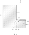
- FIG. 4 is a schematic side view of the apparatus 2 for applying the adhesive according to an embodiment of the present invention.
- the apparatus 2 for applying the adhesive includes: a side part 21 including a support surface 211 supporting one surface of the upright secondary battery 1; and a lower part 22 including an adhesion space 221 which accommodates the liquid adhesive 3 and in which the sealing part 134 disposed at the one side of the upright secondary battery 1 is inserted and a passage 222 connected to the adhesion space 221 so that the liquid adhesive 3 flows to the adhesion space 221, wherein the lower part 22 is disposed below the side part 21.
- the side part 21 of the apparatus 2 for applying the adhesive includes the support surface 211.
- the support surface 211 supports one surface of the secondary battery 1 when the secondary battery 1 is positioned upright to be inserted into the adhesion space 221.
- the support surface 211 may be flat. It is preferable that the support surface 211 is parallel to the one surface of the upright secondary battery 1. Thus, the one surface of the secondary battery 1 may be stably supported.
- the lower part 22 of the apparatus 2 for applying the adhesive 3 is disposed below the side part 21 and includes the adhesion space 221 and the passage 222.
- the side part 21 and the lower part 22 of the apparatus 2 for applying the adhesive 3 may be manufactured separately and then assembled, but the present invention is not limited thereto.
- the side part 21 and the lower part 22 may be manufactured integrally, i.e., in various manners without being limited thereto.
- the adhesion space 221 accommodates the liquid adhesive 3 (see FIG. 5 ), and the sealing part 134 disposed at the one side of the secondary battery 1 is inserted into the adhesion space 22.
- the adhesion space 221 may be recessed downward from a top surface of the lower part 22 of the apparatus 2 for applying the adhesive.
- the one surface of the secondary battery 1, which is supported by the support surface 211 may face a left or right side, and the sealing part 134 of the secondary battery may face a lower side.
- the adhesion space 221 is formed in the lower part 22 disposed below the side part 21, the sealing part 134 may be smoothly inserted into the adhesion space 221 while the secondary battery 1 is supported by the support surface 211.
- the adhesion space 221 accommodates the liquid adhesive 3.
- the sealing part 134 of the secondary battery 1 is inserted into the adhesion space 221
- the sealing part 134 of the secondary battery 1 is immersed in the liquid adhesive 3.
- the liquid adhesive 3 is applied to a portion of the sealing part 134 immersed in the liquid adhesive 3.
- an area of the sealing part 134 to be coated with the liquid adhesive 3 may be widened.
- the more an amount of liquid adhesive 3 to be accommodated may decrease.
- the area of the sealing part 134 to be coated with the liquid adhesive 3 may be narrowed.
- the liquid adhesive 3 may be a urethane acrylate (UA)-based adhesive that is cured when ultraviolet (UV) rays are irradiated.
- the urethane acrylate is a compound produced by a UV-curable urethane resin and is a general name of a compound having a urethane bond and an acrylate group together.
- the urethane acrylate is excellent in insulation, flexibility, and abrasion resistance.
- the UV rays 41 see FIG. 8
- the liquid adhesive 3 may be cured to insulate a metal exposed to a cross-section of the sealing part 134.
- the adhesion space 221 is narrower downward. That is, an upper width of the adhesion space 221 may be relatively wider than a lower width. On the other hand, the lower width of the adhesion space 221 may be relatively narrower than the upper width.
- an inner wall referred to a left inner wall in FIG. 4
- the upper inner wall 2211 may have an edge that is chamfered or filleted so that the width of the adhesion space 221 is continuously narrowed downward.
- the sealing part 134 of the secondary battery 1 may be easily inserted.
- the lower inner wall 2212 may be parallel to the support surface 211.
- the sealing part 134 of the secondary battery 1 when the sealing part 134 of the secondary battery 1 is fully inserted into the adhesion space 221, the sealing part 134 of the secondary battery 1 may be stably supported by the lower inner wall 2212.
- a stepped portion may not be formed on the inner wall 2213 (referred to a right inner wall in FIG. 4 ) which faces a side opposite to the support surface 211 in the adhesion space 221.
- the passage 222 is connected to the adhesion space 221 to provide a flow path through which the liquid adhesive 3 flows into the adhesion space 221.
- the present invention is not limited thereto. It is preferable that a plurality of passages 222 are formed so that the liquid adhesive 3 is quickly accommodated in the adhesion space 221.
- the liquid adhesive 3 may be separately provided to be stored in an adhesive tank. Also, the adhesive tank supplies the liquid adhesive 3 stored therein to a dispenser, and the dispenser injects the supplied liquid adhesive 3 to the passage 222. Thus, the liquid adhesive 3 injected into the passage 222 may flow through the passage 222 so as to be accommodated in the adhesion space 221.
- the dispenser may be provided in plurality so that the dispenser corresponding to each of the passages 222 injects the liquid adhesive 3 into the corresponding passage 222.
- the apparatus 2 for applying the adhesive has a height less than that of the secondary battery 1 when the sealing part 134 of the secondary battery 1 is inserted into the adhesion space 221.
- FIG. 5 is a schematic side view illustrating a state in which the liquid adhesive 3 is accommodated in the adhesion space 221 of the apparatus 2 for applying the adhesive according to an embodiment of the present invention.
- the liquid adhesive 3 is accommodated in the adhesion space 221 of the apparatus 2 for applying the adhesive through the passage 222 (S301).
- the adhesive tank storing the liquid adhesive 3 supplies the liquid adhesive 3 to the dispenser
- the liquid adhesive 3 may be injected into the passage 222 by using the dispenser.
- the liquid adhesive 3 may flow through the passage 222 so as to be accommodated in the adhesion space 221.
- an amount of liquid adhesive 3 is too small, the liquid adhesive 3 may not be sufficiently applied to the sealing part 134. If an amount of liquid adhesive 3 is too large, when the sealing part 134 is inserted into the adhesive space 221 and immersed in the liquid adhesive 3, the liquid adhesive 3 may leak to the outside of the adhesion space 221. Thus, an optimum amount of liquid adhesive 3, which is capable of being sufficiently applied to the sealing part 134 and does not leak to the outside of the adhesion space 221, may be experimentally derived.
- FIG. 6 is a schematic side view illustrating a state in which the sealing part 134 of the secondary battery 1 is inserted into the adhesion space 221 of the apparatus 2 for applying the adhesive according to an embodiment of the present invention
- FIG. 7 is a schematic front view illustrating a state in which the sealing part 134 of the secondary battery 1 is inserted into the adhesion space 221 of the apparatus 2 for applying the adhesive according to an embodiment of the present invention.
- the secondary battery 1 When the liquid adhesive 3 is sufficiently accommodated in the adhesion space 221, as illustrated in FIGS. 6 and 7 , the secondary battery 1 is positioned upright to insert the sealing part 134 disposed at the one side of the secondary battery 1 into the adhesion space 221 (S302).
- the secondary battery may be stably erected.
- the connected portion is folded when the upper pouch 131 covers the accommodation space 1331.
- the folded portion does not need to be coated with the liquid adhesive 3 because the metal of the pouch film is not exposed to the outside. Since the metal of the pouch film is exposed to the outside, the sealing part 134, which is not the folded portion but thermally fused portion, has to be coated with the liquid adhesive 3.
- the battery case 13 is positioned upright, the battery case 13 is positioned so that the sealing part 134 to which the liquid adhesive 3 is to be applied is disposed to face a lower side.
- the present invention is not limited thereto.
- the secondary battery 1 may be positioned upright so that the secondary battery 1 has a full length in the vertical direction.
- the sealing part 134 that is lengthily disposed in a longitudinal direction of the secondary battery 1 may be disposed to face the lower side.
- the sealing part 134 formed lengthily in the longitudinal direction is inserted into the adhesion space 221 and immersed in the liquid adhesive 3.
- the sealing part 134 formed lengthily in the width direction of the secondary battery 1 is disposed to face the lower side. Also, the sealing part 134 formed lengthily in the width direction is inserted into the adhesion space 221 and immersed in the liquid adhesive 3.
- FIG. 8 is a schematic view illustrating a state in which ultraviolet rays 41 are irradiated to the sealing part 134 of the secondary battery 1 according to an embodiment of the present invention.
- the secondary battery 1 is again withdrawn (S303).
- the liquid adhesive 3 is applied to a portion of the sealing portion 134 that is immersed in the liquid adhesive 3.
- the ultraviolet rays 41 are irradiated to the sealing part 134 to which the liquid adhesive 3 is applied by using an UV lamp 4 (S304).
- the UV lamp 4 is a lamp which irradiates the ultraviolet rays 41 to the outside.
- the ultraviolet rays 41 are an electromagnetic wave of which a wavelength is shorter than that of visible light and thus has a wavelength of approximately 10 nm to approximately 400 nm.
- the ultraviolet rays 41 have a very short wavelength and thus is invisible to the human eye and also have high energy. Thus, ultraviolet rays 41 may be easily used for sterilization and bleaching.
- the liquid adhesive 3 may be a urethane acrylate (UA)-based adhesive that is cured when the ultraviolet rays 41 are irradiated.
- U urethane acrylate
- FIG. 9 is a schematic side view of an apparatus 2a for applying an adhesive according to another embodiment of the present invention.
- the support surface 211 of the side part 21 is parallel to one surface of the secondary battery 1, and the support surface 211 extends up to the lower part 22 of the apparatus 2 for applying the adhesive.
- a portion of the liquid adhesive 3 applied to the sealing part 134 of the secondary battery 1 may drop to contaminate a top surface of the lower part 22 of the apparatus 2 for applying the adhesive.
- the liquid adhesive 3 may remain on the connected edge between the side part 21 and the lower part 22 of the apparatus 2 for applying the adhesive.
- an outer surface of the secondary battery 1 may be contaminated.
- a side part 21a of an apparatus 2a for applying an adhesive has an inclined surface 212a having a specific inclination toward the inside of the side part 21a from a lower end of a support surface 221a.
Landscapes
- Engineering & Computer Science (AREA)
- Chemical & Material Sciences (AREA)
- Chemical Kinetics & Catalysis (AREA)
- General Chemical & Material Sciences (AREA)
- Mechanical Engineering (AREA)
- Manufacturing & Machinery (AREA)
- Electrochemistry (AREA)
- Health & Medical Sciences (AREA)
- Organic Chemistry (AREA)
- Physics & Mathematics (AREA)
- Oral & Maxillofacial Surgery (AREA)
- Thermal Sciences (AREA)
- Toxicology (AREA)
- Sealing Battery Cases Or Jackets (AREA)
- Secondary Cells (AREA)
- Coating Apparatus (AREA)
- Application Of Or Painting With Fluid Materials (AREA)
Abstract
Description
- The present application claims the benefit of the priority of Korean Patent Application No.
10-2018-0143264, filed on November 20, 2018 - The present invention relates to an apparatus and method for applying an adhesive, and more particularly, to an apparatus and method for applying an adhesive, which are capable of preventing non-coating of a liquid adhesive and improving productivity of a secondary battery.
- In general, secondary batteries include nickelcadmium batteries, nickel-hydrogen batteries, lithium ion batteries, and lithium ion polymer batteries. Such a secondary battery is being applied to and used in small-sized products such as digital cameras, P-DVDs, MP3Ps, mobile phones, PDAs, portable game devices, power tools, E-bikes, and the like as well as large-sized products requiring high power such as electric vehicles and hybrid vehicles, power storage devices for storing surplus power or renewable energy, and backup power storage devices.
- In general, in order to manufacture the lithium secondary battery, first, electrode active material slurry is applied to a positive electrode collector and a negative electrode collector to manufacture a positive electrode and a negative electrode. Then, the electrodes are stacked on both sides of a separator form an electrode assembly. Also, the electrode assembly is accommodated in a battery case, an electrolyte is injected, and then, sealing is performed.
- Such a secondary battery is classified into a pouch type secondary battery and a can type secondary battery according to a material of a case accommodating the electrode assembly. In the pouch type secondary battery, an electrode assembly is accommodated in a pouch made of a flexible polymer material having a variable shape.
- When a sealing part is left as it is after the pouch type battery case is sealed, a metal of a pouch film is exposed to the outside through a cross-section of the sealing part. Thus, the metal may be corroded or come into contact with an electrode of the secondary battery to cause short circuit. As a result, it is necessary not to expose the cross-section of the sealing part.
- According to the related art, a double side folding method in which the sealing part is folded twice is performed, or a method in which an insulation tape is attached to the sealing part has been performed. However, this method has a disadvantage in that manufacturing yield is deteriorated, and a time taken to optimize the equipment is long. In order to solve this problem, recently, a method for applying a liquid adhesive to a sealing part to cure the liquid adhesive has been developed. However, a portion of a nozzle that applies the liquid adhesive may be blocked to cause a problem that the liquid adhesive is not applied to the sealing parts of some secondary batteries.
- An object to be solved by the present invention is to provide an apparatus and method for applying an adhesive, which are capable of preventing non-coating of a liquid adhesive and improving productivity of a secondary battery.
- The objects of the present invention are not limited to the aforementioned object, but other objects not described herein will be clearly understood by those skilled in the art from descriptions below.
- An apparatus for applying a liquid adhesive according to an embodiment of the present invention for solving the above object includes: a side part including a support surface configured to support one surface of an upright secondary battery; and a lower part including an adhesion space which accommodates the liquid adhesive and in which a sealing part disposed at the one surface of the upright secondary battery is inserted and a passage connected to the adhesion space so that the liquid adhesive flows to the adhesion space, wherein the lower part is disposed below the side part.
- Also, the adhesion space may be recessed downward from a top surface of the lower part.
- Also, the adhesion space may have a width that is gradually narrowed downward.
- Also, in the adhesion space, an inner wall facing the support surface may include an upper inner wall of which an edge is chamfered or filleted and a lower inner wall that is parallel to the support surface.
- Also, the apparatus may further include a dispenser configured to inject the liquid adhesive into the passage.
- Also, the apparatus may further include an adhesive tank that stores the liquid adhesive to supply the liquid adhesive to the dispenser.
- Also, the passage may be provided in plurality.
- Also, the side part may further include an inclined surface having a specific inclination toward the inside of the side part from a lower end of the support surface.
- A method for applying a liquid adhesive according to an embodiment of the present invention for solving the above object includes: a step of accommodating the liquid adhesive in an adhesion space of an apparatus for applying the liquid adhesive through a passage; a step of positioning the secondary battery upright and inserting a sealing part disposed at one side of the secondary battery into the adhesion space; a step of withdrawing the secondary battery; and a step of irradiating ultraviolet rays to the sealing part coated with the liquid adhesive.
- Also, in the step of injecting the liquid adhesive, the liquid adhesive may be injected into the passage by using a dispenser.
- Also, the dispenser may receive the liquid adhesive from an adhesive tank storing the liquid adhesive to inject the liquid adhesive into the passage.
- Also, in the step of injecting the sealing part, the secondary battery may have one surface supported by a support surface of the apparatus for applying the adhesive, and the sealing part disposed at the one side of the secondary battery may be inserted into the adhesion space.
- Also, the liquid adhesive may be a urethane acrylate-based adhesive.
- Particularities of other embodiments are included in the detailed description and drawings.
- The embodiments of the present invention may have at least the following effects.
- Since a nozzle is not used, the non-coating of the liquid adhesive due to the blocking of the nozzle may be prevented.
- Also, since it is unnecessary to set the line, along which the nozzle moves to apply the liquid adhesive, and the coating time, the manufacturing yield may be improved, and also, the productivity of the secondary battery may be improved.
- The effects of the prevent invention are not limited by the aforementioned description, and thus, more varied effects are involved in this specification.
-
-
FIG. 1 is an assembled view of a pouch type secondary battery according to an embodiment of the present invention. -
FIG. 2 is a perspective view of the pouch type secondary battery according to an embodiment of the present invention. -
FIG. 3 is a flowchart illustrating a method for applying an adhesive according to an embodiment of the present invention. -
FIG. 4 is a schematic side view of an apparatus for applying an adhesive according to an embodiment of the present invention. -
FIG. 5 is a schematic side view illustrating a state in which a liquid adhesive is accommodated in an adhesion space of the apparatus for applying the adhesive according to an embodiment of the present invention. -
FIG. 6 is a schematic side view illustrating a state in which a sealing part of the secondary battery is inserted into the adhesion space of the apparatus for applying the adhesive according to an embodiment of the present invention. -
FIG. 7 is a schematic front view illustrating a state in which the sealing part of the secondary battery is inserted into the adhesion space of the apparatus for applying the adhesive according to an embodiment of the present invention. -
FIG. 8 is a schematic view illustrating a state in which ultraviolet rays are irradiated to the sealing part of the secondary battery according to an embodiment of the present invention. -
FIG. 9 is a schematic side view of an apparatus for applying an adhesive according to another embodiment of the present invention. - Advantages and features of the present disclosure, and implementation methods thereof will be clarified through following embodiments described with reference to the accompanying drawings. The present invention may, however be embodied in different forms and should not be construed as limited to the embodiments set forth herein. Rather, these embodiments are provided so that this disclosure will be thorough and complete, and will fully convey the scope of the present invention to those skilled in the art. Further, the present invention is only defined by scopes of claims. Like reference numerals refer to like elements throughout.
- Unless terms used in the present invention are defined differently, all terms (including technical and scientific terms) used herein have the same meaning as generally understood by those skilled in the art. Also, unless defined clearly and apparently in the description, the terms as defined in a commonly used dictionary are not ideally or excessively construed as having formal meaning.
- In the following description, the technical terms are used only for explaining a specific exemplary embodiment while not limiting the present invention. In this specification, the terms of a singular form may comprise plural forms unless specifically mentioned. The meaning of "comprises" and/or "comprising" does not exclude other components besides a mentioned component.
- Hereinafter, preferred embodiments will be described in detail with reference to the accompanying drawings.
-
FIG. 1 is an assembled view of a pouch type secondary battery according to an embodiment of the present invention, andFIG. 2 is a perspective view of the pouch type secondary battery according to an embodiment of the present invention. - In a process of manufacturing a pouch type
secondary battery 1 according to an embodiment of the present invention, first, slurry in which an electrode active material, a binder, and a plasticizer are mixed with each other is applied to a positive electrode collector and a negative electrode collector to manufacture a positive electrode and a negative electrode. Thereafter, the negative electrode collector and the positive electrode plate are respectively laminated on both sides of a separator to form anelectrode assembly 10 having a predetermined shape, and then, theelectrode assembly 10 is inserted into abattery case 13, an electrolyte is injected, and sealing is performed. - As illustrated in
FIG. 1 , theelectrode assembly 10 includes anelectrode tab 11. Theelectrode tab 11 is connected to each of a positive electrode and a negative electrode of theelectrode assembly 10 to protrude to the outside of theelectrode assembly 10, thereby providing a path, through which electrons are moved, between the inside and outside of theelectrode assembly 10. A collector of theelectrode assembly 10 is constituted by a portion coated with an electrode active material and a distal end, on which the electrode active material is not applied, i.e., a non-coating portion. Also, theelectrode tab 11 may be formed by cutting the non-coating portion or by connecting a separate conductive member to the non-coating portion through ultrasonic welding. As illustrated inFIG. 1 , theelectrode tabs 11 may protrude from one side of theelectrode assembly 10 in the same direction, but the present invention is not limited thereto. For example, theelectrode tabs 11 may protrude in directions different from each other. - In the
electrode assembly 10, theelectrode lead 12 is connected to theelectrode tab 11 through spot welding. Also, a portion of theelectrode lead 12 is surrounded by an insulation part. The insulation part may be disposed to be limited within a sealingpart 134, at which anupper pouch 131 and alower pouch 132 of thebattery case 13 are thermally fused, so that theelectrode lead 12 is bonded to thebattery case 13. Also, electricity generated from theelectrode assembly 10 may be prevented from flowing to thebattery case 13 through theelectrode lead 12, and the sealing of thebattery case 13 may be maintained. Thus, the insulation part may be made of a nonconductor having non-conductivity, which is not electrically conductive. In general, although an insulation tape which is easily attached to theelectrode lead 12 and has a relatively thin thickness is mainly used as the insulation part, the present invention is not limited thereto. For example, various members may be used as the insulation part as long as the members are capable of insulating theelectrode lead 12. - The
electrode lead 12 may extend in the same direction or extend in directions different from each other according to the formation positions of thepositive electrode tab 111 and thenegative electrode tab 112. Thepositive electrode lead 121 and thenegative electrode lead 122 may be made of materials different from each other. That is, thepositive electrode lead 121 may be made of the same material as the positive electrode plate, i.e., an aluminum (Al) material, and thenegative electrode lead 122 may be made of the same material as the negative electrode plate, i.e., a copper (Cu) material or a copper material coated with nickel (Ni). Also, a portion of theelectrode lead 12, which protrudes to the outside of thebattery case 13, may be provided as a terminal part and electrically connected to an external terminal. - In the pouch type
secondary battery 1 according to an embodiment of the present invention, thebattery case 13 may be a pouch made of a flexible material. Hereinafter, the case in which thebattery case 13 is the pouch will be described. Thebattery case 13 accommodates theelectrode assembly 10 so that a portion of theelectrode lead 12, i.e., the terminal part is exposed and then is sealed. As illustrated inFIG. 1 , thebattery case 13 includes theupper pouch 131 and thelower pouch 132. Anaccommodation space 1331 in which theelectrode assembly 10 is accommodated may be provided in thelower pouch 132, andupper pouch 131 may cover an upper side of theaccommodation space 1331 so that theelectrode assembly 10 is not separated to the outside of thebattery case 13. Here, as illustrated inFIG. 1 , theaccommodation space 1331 may also be provided in theupper pouch 131 to accommodate theelectrode assembly 10 through an upper side of theupper pouch 131. As illustrated inFIG. 1 , one side of theupper pouch 131 and one side of thelower pouch 132 may be connected to each other. However, the present invention is not limited thereto. For example, theupper pouch 131 and the lower pouch may be separately manufactured to be separated from each other. - When the
electrode lead 12 is connected to theelectrode tab 11 of theelectrode assembly 10, and the insulation part is provided on a portion of theelectrode lead 12, theelectrode assembly 10 may be accommodated in theaccommodation space 1331 provided in thelower pouch 132, and theupper pouch 131 may cover the upper side of theaccommodation space 1331. Also, when the electrolyte is injected, and the sealingpart 134 provided on the edge of each of theupper pouch 131 and thelower pouch 132 is sealed, thesecondary battery 1 is manufactured as illustrated inFIG. 2 . -
FIG. 3 is a flowchart illustrating a method for applying an adhesive according to an embodiment of the present invention. - In a method for applying an adhesive according to the present invention, since a nozzle is not used, non-coating of a
liquid adhesive 3 due to blocking of the nozzle may be prevented. Also, since it is unnecessary to set a line, along which the nozzle moves to apply theliquid adhesive 3, and a coating time, manufacturing yield may be improved, and also, productivity of asecondary battery 1 may be improved. - For this, the method for applying the adhesive according to an embodiment of the present invention includes: a step of accommodating the
liquid adhesive 3 in anadhesion space 221 of anapparatus 2 for applying an adhesive through apassage 222; a step of standing up thesecondary battery 1 to insert a sealingpart 134 disposed at one side of thesecondary battery 1 into theadhesion space 221; a step of withdrawing thesecondary battery 1; and a step of irradiating ultraviolet rays to the sealingpart 134 coated with theliquid adhesive 3. - Hereinafter, each of the steps illustrated in the flowchart of
FIG. 3 will be described with reference toFIGS. 4 to 8 . -
FIG. 4 is a schematic side view of theapparatus 2 for applying the adhesive according to an embodiment of the present invention. - As illustrated in
FIG. 4 , theapparatus 2 for applying the adhesive according to the present invention includes: aside part 21 including asupport surface 211 supporting one surface of the uprightsecondary battery 1; and alower part 22 including anadhesion space 221 which accommodates theliquid adhesive 3 and in which the sealingpart 134 disposed at the one side of the uprightsecondary battery 1 is inserted and apassage 222 connected to theadhesion space 221 so that theliquid adhesive 3 flows to theadhesion space 221, wherein thelower part 22 is disposed below theside part 21. - The
side part 21 of theapparatus 2 for applying the adhesive includes thesupport surface 211. Thesupport surface 211 supports one surface of thesecondary battery 1 when thesecondary battery 1 is positioned upright to be inserted into theadhesion space 221. For this purpose, thesupport surface 211 may be flat. It is preferable that thesupport surface 211 is parallel to the one surface of the uprightsecondary battery 1. Thus, the one surface of thesecondary battery 1 may be stably supported. - The
lower part 22 of theapparatus 2 for applying the adhesive 3 is disposed below theside part 21 and includes theadhesion space 221 and thepassage 222. Theside part 21 and thelower part 22 of theapparatus 2 for applying the adhesive 3 may be manufactured separately and then assembled, but the present invention is not limited thereto. For example, theside part 21 and thelower part 22 may be manufactured integrally, i.e., in various manners without being limited thereto. - The
adhesion space 221 accommodates the liquid adhesive 3 (seeFIG. 5 ), and the sealingpart 134 disposed at the one side of thesecondary battery 1 is inserted into theadhesion space 22. For this, as illustrated inFIG. 4 , theadhesion space 221 may be recessed downward from a top surface of thelower part 22 of theapparatus 2 for applying the adhesive. When thesecondary battery 1 is positioned upright, the one surface of thesecondary battery 1, which is supported by thesupport surface 211, may face a left or right side, and the sealingpart 134 of the secondary battery may face a lower side. Thus, since theadhesion space 221 is formed in thelower part 22 disposed below theside part 21, the sealingpart 134 may be smoothly inserted into theadhesion space 221 while thesecondary battery 1 is supported by thesupport surface 211. - The
adhesion space 221 accommodates theliquid adhesive 3. Thus, when the sealingpart 134 of thesecondary battery 1 is inserted into theadhesion space 221, the sealingpart 134 of thesecondary battery 1 is immersed in theliquid adhesive 3. Also, when thesecondary battery 1 is withdrawn again, theliquid adhesive 3 is applied to a portion of the sealingpart 134 immersed in theliquid adhesive 3. Thus, the more theadhesion space 221 increases in depth, the more an amount ofliquid adhesive 3 to be accommodated may increase. As a result, an area of the sealingpart 134 to be coated with theliquid adhesive 3 may be widened. Also, as the more theadhesion space 221 decreases in depth, the more an amount ofliquid adhesive 3 to be accommodated may decrease. As a result, the area of the sealingpart 134 to be coated with theliquid adhesive 3 may be narrowed. - The
liquid adhesive 3 may be a urethane acrylate (UA)-based adhesive that is cured when ultraviolet (UV) rays are irradiated. The urethane acrylate is a compound produced by a UV-curable urethane resin and is a general name of a compound having a urethane bond and an acrylate group together. The urethane acrylate is excellent in insulation, flexibility, and abrasion resistance. Thus, when the UV rays 41 (seeFIG. 8 ) is irradiated to theliquid adhesive 3 applied to the sealingpart 134, theliquid adhesive 3 may be cured to insulate a metal exposed to a cross-section of the sealingpart 134. - The
adhesion space 221 is narrower downward. That is, an upper width of theadhesion space 221 may be relatively wider than a lower width. On the other hand, the lower width of theadhesion space 221 may be relatively narrower than the upper width. Particularly, as illustrated inFIG. 4 , an inner wall (referred to a left inner wall inFIG. 4 ) which faces thesupport surface 211 in theadhesion space 221 may include an upperinner wall 2211 and a lowerinner wall 2212. Also, the upperinner wall 2211 may have an edge that is chamfered or filleted so that the width of theadhesion space 221 is continuously narrowed downward. Thus, the sealingpart 134 of thesecondary battery 1 may be easily inserted. Also, the lowerinner wall 2212 may be parallel to thesupport surface 211. Thus, when the sealingpart 134 of thesecondary battery 1 is fully inserted into theadhesion space 221, the sealingpart 134 of thesecondary battery 1 may be stably supported by the lowerinner wall 2212. A stepped portion may not be formed on the inner wall 2213 (referred to a right inner wall inFIG. 4 ) which faces a side opposite to thesupport surface 211 in theadhesion space 221. Thus, there may be no obstacle that prevents the insertion of thesealing unit 134 of thesecondary battery 1. - The
passage 222 is connected to theadhesion space 221 to provide a flow path through which theliquid adhesive 3 flows into theadhesion space 221. Although only onepassage 222 is formed, the present invention is not limited thereto. It is preferable that a plurality ofpassages 222 are formed so that theliquid adhesive 3 is quickly accommodated in theadhesion space 221. - Although not shown, the
liquid adhesive 3 may be separately provided to be stored in an adhesive tank. Also, the adhesive tank supplies theliquid adhesive 3 stored therein to a dispenser, and the dispenser injects the suppliedliquid adhesive 3 to thepassage 222. Thus, theliquid adhesive 3 injected into thepassage 222 may flow through thepassage 222 so as to be accommodated in theadhesion space 221. When thepassage 222 is provided in plurality, only one dispenser may be formed to inject theliquid adhesive 3 into eachpassage 222 while moving. However, the present invention is not limited thereto. For example, the dispenser may be provided in plurality so that the dispenser corresponding to each of thepassages 222 injects theliquid adhesive 3 into thecorresponding passage 222. - In order to insert the sealing
part 134 of thesecondary battery 1 into theadhesion space 221, a user has to directly grip an upper portion of thesecondary battery 1 or grip the upper portion of thesecondary battery 1 by using a separate gripper. However, if a height of theapparatus 2 for applying the adhesive is greater than that of thesecondary battery 1, thesupport surface 211 and the user's hand or the gripper may collide with each other. Thus, it is preferable that theapparatus 2 for applying the adhesive has a height less than that of thesecondary battery 1 when the sealingpart 134 of thesecondary battery 1 is inserted into theadhesion space 221. -
FIG. 5 is a schematic side view illustrating a state in which theliquid adhesive 3 is accommodated in theadhesion space 221 of theapparatus 2 for applying the adhesive according to an embodiment of the present invention. - In order to apply the adhesive to the sealing
part 134 of thesecondary battery 1, as illustrated inFIG. 5 , first, theliquid adhesive 3 is accommodated in theadhesion space 221 of theapparatus 2 for applying the adhesive through the passage 222 (S301). Here, when the adhesive tank storing theliquid adhesive 3 supplies theliquid adhesive 3 to the dispenser, theliquid adhesive 3 may be injected into thepassage 222 by using the dispenser. Thus, theliquid adhesive 3 may flow through thepassage 222 so as to be accommodated in theadhesion space 221. - If an amount of
liquid adhesive 3 is too small, theliquid adhesive 3 may not be sufficiently applied to the sealingpart 134. If an amount ofliquid adhesive 3 is too large, when the sealingpart 134 is inserted into theadhesive space 221 and immersed in theliquid adhesive 3, theliquid adhesive 3 may leak to the outside of theadhesion space 221. Thus, an optimum amount ofliquid adhesive 3, which is capable of being sufficiently applied to the sealingpart 134 and does not leak to the outside of theadhesion space 221, may be experimentally derived. -
FIG. 6 is a schematic side view illustrating a state in which the sealingpart 134 of thesecondary battery 1 is inserted into theadhesion space 221 of theapparatus 2 for applying the adhesive according to an embodiment of the present invention, andFIG. 7 is a schematic front view illustrating a state in which the sealingpart 134 of thesecondary battery 1 is inserted into theadhesion space 221 of theapparatus 2 for applying the adhesive according to an embodiment of the present invention. - When the
liquid adhesive 3 is sufficiently accommodated in theadhesion space 221, as illustrated inFIGS. 6 and7 , thesecondary battery 1 is positioned upright to insert the sealingpart 134 disposed at the one side of thesecondary battery 1 into the adhesion space 221 (S302). Here, when one surface of thesecondary battery 1 is supported by thesupport surface 211 of theapparatus 2 for applying the adhesive, the secondary battery may be stably erected. - If the
upper pouch 131 and thelower pouch 132 of thebattery case 13 are manufactured by connecting one side of theupper pouch 131 to one side of thelower pouch 132, the connected portion is folded when theupper pouch 131 covers theaccommodation space 1331. The folded portion does not need to be coated with theliquid adhesive 3 because the metal of the pouch film is not exposed to the outside. Since the metal of the pouch film is exposed to the outside, the sealingpart 134, which is not the folded portion but thermally fused portion, has to be coated with theliquid adhesive 3. Thus, when thebattery case 13 is positioned upright, thebattery case 13 is positioned so that the sealingpart 134 to which theliquid adhesive 3 is to be applied is disposed to face a lower side. - Although the secondary battery is positioned upright so that the
secondary battery 1 has a full width in a vertical direction inFIGS. 6 and7 , the present invention is not limited thereto. For example, thesecondary battery 1 may be positioned upright so that thesecondary battery 1 has a full length in the vertical direction. If thesecondary battery 1 is positioned so that thesecondary battery 1 has the full width in the vertical direction, the sealingpart 134 that is lengthily disposed in a longitudinal direction of thesecondary battery 1 may be disposed to face the lower side. Also, the sealingpart 134 formed lengthily in the longitudinal direction is inserted into theadhesion space 221 and immersed in theliquid adhesive 3. However, if thesecondary battery 1 is positioned so that thesecondary battery 1 has the full length in the vertical direction, the sealingpart 134 formed lengthily in the width direction of thesecondary battery 1 is disposed to face the lower side. Also, the sealingpart 134 formed lengthily in the width direction is inserted into theadhesion space 221 and immersed in theliquid adhesive 3. -
FIG. 8 is a schematic view illustrating a state in which ultraviolet rays 41 are irradiated to the sealingpart 134 of thesecondary battery 1 according to an embodiment of the present invention. - After the sealing
part 134 of thesecondary battery 1 is fully immersed in theliquid adhesive 3, thesecondary battery 1 is again withdrawn (S303). Thus, theliquid adhesive 3 is applied to a portion of the sealingportion 134 that is immersed in theliquid adhesive 3. Also, as illustrated inFIG. 8 , the ultraviolet rays 41 are irradiated to the sealingpart 134 to which theliquid adhesive 3 is applied by using an UV lamp 4 (S304). - The
UV lamp 4 is a lamp which irradiates the ultraviolet rays 41 to the outside. Also, the ultraviolet rays 41 are an electromagnetic wave of which a wavelength is shorter than that of visible light and thus has a wavelength of approximately 10 nm to approximately 400 nm. The ultraviolet rays 41 have a very short wavelength and thus is invisible to the human eye and also have high energy. Thus, ultraviolet rays 41 may be easily used for sterilization and bleaching. - As described above, the
liquid adhesive 3 may be a urethane acrylate (UA)-based adhesive that is cured when the ultraviolet rays 41 are irradiated. Thus, when the UV rays 41 is irradiated to theliquid adhesive 3 applied to the sealingpart 134, theliquid adhesive 3 may be cured to insulate a metal exposed to a cross-section of the sealingpart 134. -
FIG. 9 is a schematic side view of anapparatus 2a for applying an adhesive according to another embodiment of the present invention. - In the
apparatus 2 for applying an adhesive according to an embodiment of the present invention, thesupport surface 211 of theside part 21 is parallel to one surface of thesecondary battery 1, and thesupport surface 211 extends up to thelower part 22 of theapparatus 2 for applying the adhesive. However, when the sealingportion 134 of thesecondary battery 1 is withdrawn after being immersed in theliquid adhesive 3, a portion of theliquid adhesive 3 applied to the sealingpart 134 of thesecondary battery 1 may drop to contaminate a top surface of thelower part 22 of theapparatus 2 for applying the adhesive. However, even if the droppingliquid adhesive 3 is cleanly cleaned, theliquid adhesive 3 may remain on the connected edge between theside part 21 and thelower part 22 of theapparatus 2 for applying the adhesive. As a result, when the sealingpart 134 of thesecondary battery 1 is inserted into theadhesion space 221 later, an outer surface of thesecondary battery 1 may be contaminated. - According to another embodiment of the present invention, as illustrated in
FIG. 9 , aside part 21a of anapparatus 2a for applying an adhesive has aninclined surface 212a having a specific inclination toward the inside of theside part 21a from a lower end of a support surface 221a. Thus, it is easy to visually determine whether theliquid adhesive 3 is contaminated on the top surface of thelower part 22, and the top surface of the contaminatedlower part 22 may be easily cleaned. Also, the outer surface of thesecondary battery 1 may be prevented from being contaminated. - Those with ordinary skill in the technical field of the present invention pertains will be understood that the present invention can be carried out in other specific forms without changing the technical idea or essential features. Therefore, the above-disclosed embodiments are to be considered illustrative and not restrictive. Accordingly, the scope of the present invention is defined by the appended claims rather than the foregoing description and the exemplary embodiments described therein. Various modifications made within the meaning of an equivalent of the claims of the invention and within the claims are to be regarded to be in the scope of the present invention.
Claims (13)
- An apparatus for applying a liquid adhesive, the apparatus comprising:a side part comprising a support surface configured to support one surface of an upright secondary battery; anda lower part comprising an adhesion space which accommodates the liquid adhesive and in which a sealing part disposed at the one surface of the upright secondary battery is inserted and a passage connected to the adhesion space so that the liquid adhesive flows to the adhesion space,wherein the lower part is disposed below the side part.
- The apparatus of claim 1, wherein the adhesion space is recessed downward from a top surface of the lower part.
- The apparatus of claim 2, wherein the adhesion space has a width that is gradually narrowed downward.
- The apparatus of claim 3, wherein, in the adhesion space, an inner wall facing the support surface comprises an upper inner wall of which an edge is chamfered or filleted and a lower inner wall that is parallel to the support surface.
- The apparatus of claim 1, further comprising a dispenser configured to inject the liquid adhesive into the passage.
- The apparatus of claim 5, further comprising an adhesive tank that stores the liquid adhesive to supply the liquid adhesive to the dispenser.
- The apparatus of claim 1, wherein the passage is provided in plurality.
- The apparatus of claim 1, wherein the side part further comprises an inclined surface having a specific inclination toward the inside of the side part from a lower end of the support surface.
- A method for applying a liquid adhesive, the method comprising:a step of accommodating the liquid adhesive in an adhesion space of an apparatus for applying the adhesive through a passage;a step of positioning the secondary battery upright and inserting a sealing part disposed at one side of the secondary battery into the adhesion space;a step of withdrawing the secondary battery; anda step of irradiating ultraviolet rays to the sealing part coated with the liquid adhesive.
- The method of claim 9, wherein, in the step of injecting the liquid adhesive, the liquid adhesive is injected into the passage by using a dispenser.
- The method of claim 10, wherein the dispenser receives the liquid adhesive from an adhesive tank storing the liquid adhesive to inject the liquid adhesive into the passage.
- The method of claim 9, wherein, in the step of injecting the sealing part, the secondary battery has one surface supported by a support surface of the apparatus for applying the adhesive, and the sealing part disposed at the one side of the secondary battery is inserted into the adhesion space.
- The method of claim 9, wherein the liquid adhesive is a urethane acrylate-based adhesive.
Applications Claiming Priority (2)
| Application Number | Priority Date | Filing Date | Title |
|---|---|---|---|
| KR1020180143264A KR102363976B1 (en) | 2018-11-20 | 2018-11-20 | The Apparatus And The Method For Applying Glue |
| PCT/KR2019/010932 WO2020105848A1 (en) | 2018-11-20 | 2019-08-27 | Apparatus for applying adhesive and method for applying adhesive |
Publications (3)
| Publication Number | Publication Date |
|---|---|
| EP3753716A1 true EP3753716A1 (en) | 2020-12-23 |
| EP3753716A4 EP3753716A4 (en) | 2021-04-14 |
| EP3753716B1 EP3753716B1 (en) | 2025-03-19 |
Family
ID=70741855
Family Applications (1)
| Application Number | Title | Priority Date | Filing Date |
|---|---|---|---|
| EP19886263.3A Active EP3753716B1 (en) | 2018-11-20 | 2019-08-27 | Apparatus and method for applying adhesive |
Country Status (9)
| Country | Link |
|---|---|
| US (1) | US11633923B2 (en) |
| EP (1) | EP3753716B1 (en) |
| JP (1) | JP7107489B2 (en) |
| KR (1) | KR102363976B1 (en) |
| CN (2) | CN211707240U (en) |
| ES (1) | ES3023063T3 (en) |
| HU (1) | HUE071026T2 (en) |
| PL (1) | PL3753716T3 (en) |
| WO (1) | WO2020105848A1 (en) |
Families Citing this family (2)
| Publication number | Priority date | Publication date | Assignee | Title |
|---|---|---|---|---|
| US20240055703A1 (en) * | 2021-11-03 | 2024-02-15 | Lg Energy Solution, Ltd. | Curved Battery Cell |
| US20250205937A1 (en) * | 2022-07-21 | 2025-06-26 | Threebond Co., Ltd. | Gasket molding method, gasket, fuel cell component, fuel cell, fuel cell production method, sealing method, and gasket molding device |
Family Cites Families (26)
| Publication number | Priority date | Publication date | Assignee | Title |
|---|---|---|---|---|
| JPH01242163A (en) | 1988-03-25 | 1989-09-27 | Jidosha Kiki Co Ltd | Method and apparatus for coating peripheral shear caulked part of paint shell |
| US5489409A (en) | 1993-06-25 | 1996-02-06 | Asahi Glass Company, Ltd. | Method of making a window frame and a window panel with a window frame |
| JP3815803B2 (en) * | 1993-07-02 | 2006-08-30 | 旭硝子株式会社 | Method for manufacturing window with synthetic resin frame |
| CA2207801C (en) * | 1996-06-19 | 2004-03-30 | Hideki Kaido | Nonaqueous electrolyte battery |
| JPH1168136A (en) * | 1997-08-08 | 1999-03-09 | Sekisui Chem Co Ltd | Solar cell module, manufacturing method and mounting structure thereof |
| US6165547A (en) * | 1998-11-12 | 2000-12-26 | Ppg Industries Ohio, Inc. | Rolled edge seal for electrooptic device |
| JP3825738B2 (en) | 2002-10-31 | 2006-09-27 | 三洋電機株式会社 | Pack battery and manufacturing method thereof |
| KR100800970B1 (en) * | 2006-01-18 | 2008-02-11 | 주식회사 엘지화학 | Binder of Polyvinyl Alcohol Crosslinked with Polyurethane and Lithium Secondary Battery Employed with the Same |
| CN100401431C (en) | 2006-08-02 | 2008-07-09 | 中利科技集团股份有限公司 | Hot melt glue applicator |
| JP4931948B2 (en) * | 2009-02-19 | 2012-05-16 | シャープ株式会社 | Solar cell module |
| CN102336302A (en) | 2010-07-27 | 2012-02-01 | 深圳富泰宏精密工业有限公司 | Liquid dipping device and method |
| CN201862534U (en) * | 2010-11-19 | 2011-06-15 | 哈尔滨光宇电源股份有限公司 | Automatic glue dispenser of square lithium ion battery |
| CN102019251B (en) | 2010-11-25 | 2012-11-21 | 深圳市豪鹏科技有限公司 | Rubber dip machine |
| JP5766132B2 (en) | 2012-01-30 | 2015-08-19 | 京セラ株式会社 | Cell stack device and fuel cell device |
| CN103567109B (en) | 2012-07-26 | 2015-12-16 | 耐落螺丝(昆山)有限公司 | Screw sizer and coating method |
| JP6039394B2 (en) | 2012-12-13 | 2016-12-07 | 株式会社Jcu | Coat tank and dip coater |
| CN105098253A (en) | 2014-05-21 | 2015-11-25 | 东莞新能源科技有限公司 | A double-folding device for flexible packaging lithium-ion batteries |
| CN204018121U (en) | 2014-06-25 | 2014-12-17 | 昆山圆裕电子科技有限公司 | FPC is sealing equipment in batches |
| KR101748645B1 (en) | 2014-11-17 | 2017-06-19 | 주식회사 엘지화학 | Battery Module |
| KR101852250B1 (en) * | 2015-04-02 | 2018-04-26 | 주식회사 엘지화학 | Sealing tool for a pouch type secondary battery |
| JP6380219B2 (en) | 2015-04-23 | 2018-08-29 | トヨタ自動車株式会社 | Manufacturing method of assembled battery and assembled battery |
| CN105826612B (en) | 2016-04-19 | 2019-04-05 | 宁德新能源科技有限公司 | A kind of edge sealing method of secondary lithium battery |
| CN205797689U (en) | 2016-06-27 | 2016-12-14 | 东莞市卓安精机自动化设备有限公司 | A side sealing machine for soft-packed lithium batteries |
| CN206104251U (en) | 2016-07-09 | 2017-04-19 | 苏州贝克诺斯电子科技股份有限公司 | Dispensing valve soaks and places tool |
| CN206009108U (en) | 2016-07-25 | 2017-03-15 | 青岛海力威新材料科技股份有限公司 | A kind of novel framework dip-coating adhesive device |
| KR20180083123A (en) | 2017-01-12 | 2018-07-20 | 주식회사 엘지화학 | External insulating method of pouch type secondary battery |
-
2018
- 2018-11-20 KR KR1020180143264A patent/KR102363976B1/en active Active
-
2019
- 2019-08-27 HU HUE19886263A patent/HUE071026T2/en unknown
- 2019-08-27 WO PCT/KR2019/010932 patent/WO2020105848A1/en not_active Ceased
- 2019-08-27 ES ES19886263T patent/ES3023063T3/en active Active
- 2019-08-27 JP JP2021525574A patent/JP7107489B2/en active Active
- 2019-08-27 PL PL19886263.3T patent/PL3753716T3/en unknown
- 2019-08-27 US US16/982,243 patent/US11633923B2/en active Active
- 2019-08-27 EP EP19886263.3A patent/EP3753716B1/en active Active
- 2019-11-19 CN CN201922000751.4U patent/CN211707240U/en active Active
- 2019-11-19 CN CN201911135245.4A patent/CN111195580B/en active Active
Also Published As
| Publication number | Publication date |
|---|---|
| EP3753716B1 (en) | 2025-03-19 |
| JP2022507148A (en) | 2022-01-18 |
| CN211707240U (en) | 2020-10-20 |
| HUE071026T2 (en) | 2025-07-28 |
| CN111195580A (en) | 2020-05-26 |
| CN111195580B (en) | 2022-03-25 |
| ES3023063T3 (en) | 2025-05-29 |
| EP3753716A4 (en) | 2021-04-14 |
| US20210031462A1 (en) | 2021-02-04 |
| KR102363976B1 (en) | 2022-02-17 |
| JP7107489B2 (en) | 2022-07-27 |
| WO2020105848A1 (en) | 2020-05-28 |
| KR20200058753A (en) | 2020-05-28 |
| PL3753716T3 (en) | 2025-06-09 |
| US11633923B2 (en) | 2023-04-25 |
Similar Documents
| Publication | Publication Date | Title |
|---|---|---|
| EP3709392B1 (en) | Secondary battery | |
| US20220416374A1 (en) | Apparatus and Method for Bending Electrode Tab | |
| US8227111B2 (en) | Secondary battery having electrolyte sealing plug | |
| EP2557609B1 (en) | Rechargeable battery and method for fabricating the same | |
| KR101528001B1 (en) | Electrode assembly, manufacture thereof, and secondary batteries including same | |
| EP3916830A1 (en) | Secondary battery battery case and pouch-type secondary battery | |
| TWI222233B (en) | Method for treating electrode tabs of crude cell for lithium secondary battery and crude cell and lithium secondary battery according to the method | |
| CN101578722B (en) | Secondary battery and manufacturing method thereof | |
| KR102164460B1 (en) | Pressing tray | |
| EP3346520A1 (en) | Battery cell and method for manufacturing same | |
| US11577447B2 (en) | Pouch forming apparatus and method | |
| CN110048068A (en) | Secondary cell | |
| KR20210027992A (en) | The Apparatus And The Method For Applying Glue | |
| US20260045577A1 (en) | Pouch Type Battery Case and Pouch Type Secondary Battery | |
| KR20120042592A (en) | Rechargeable battery | |
| EP3753716B1 (en) | Apparatus and method for applying adhesive | |
| KR20150084270A (en) | Manufacturing method of lithium secondary battery | |
| JP6404577B2 (en) | Non-aqueous electrolyte secondary battery and manufacturing method thereof | |
| KR101086359B1 (en) | Cap assembly for secondary battery and secondary battery using same | |
| KR20140134916A (en) | Method for manufacturing pouch for secondary battery and pouch of secondary battery | |
| US20220393316A1 (en) | Method for Manufacturing Electrode Lead and Pouch Type Secondary Battery | |
| EP4044357A1 (en) | Method for manufacturing electrode lead, and pressurizer | |
| US20250246769A1 (en) | Secondary battery | |
| KR101576745B1 (en) | Manufacturing method and(of) electrode for battery |
Legal Events
| Date | Code | Title | Description |
|---|---|---|---|
| STAA | Information on the status of an ep patent application or granted ep patent |
Free format text: STATUS: THE INTERNATIONAL PUBLICATION HAS BEEN MADE |
|
| PUAI | Public reference made under article 153(3) epc to a published international application that has entered the european phase |
Free format text: ORIGINAL CODE: 0009012 |
|
| STAA | Information on the status of an ep patent application or granted ep patent |
Free format text: STATUS: REQUEST FOR EXAMINATION WAS MADE |
|
| 17P | Request for examination filed |
Effective date: 20200914 |
|
| AK | Designated contracting states |
Kind code of ref document: A1 Designated state(s): AL AT BE BG CH CY CZ DE DK EE ES FI FR GB GR HR HU IE IS IT LI LT LU LV MC MK MT NL NO PL PT RO RS SE SI SK SM TR |
|
| AX | Request for extension of the european patent |
Extension state: BA ME |
|
| A4 | Supplementary search report drawn up and despatched |
Effective date: 20210315 |
|
| RIC1 | Information provided on ipc code assigned before grant |
Ipc: B29C 65/48 20060101AFI20210309BHEP Ipc: C09J 175/14 20060101ALI20210309BHEP Ipc: B29C 35/08 20060101ALI20210309BHEP Ipc: B32B 37/00 20060101ALI20210309BHEP |
|
| RAP3 | Party data changed (applicant data changed or rights of an application transferred) |
Owner name: LG ENERGY SOLUTION, LTD. |
|
| RAP3 | Party data changed (applicant data changed or rights of an application transferred) |
Owner name: LG CHEM, LTD. |
|
| DAV | Request for validation of the european patent (deleted) | ||
| DAX | Request for extension of the european patent (deleted) | ||
| STAA | Information on the status of an ep patent application or granted ep patent |
Free format text: STATUS: EXAMINATION IS IN PROGRESS |
|
| 17Q | First examination report despatched |
Effective date: 20230104 |
|
| RAP1 | Party data changed (applicant data changed or rights of an application transferred) |
Owner name: LG ENERGY SOLUTION, LTD. |
|
| GRAP | Despatch of communication of intention to grant a patent |
Free format text: ORIGINAL CODE: EPIDOSNIGR1 |
|
| STAA | Information on the status of an ep patent application or granted ep patent |
Free format text: STATUS: GRANT OF PATENT IS INTENDED |
|
| RIC1 | Information provided on ipc code assigned before grant |
Ipc: B32B 37/12 20060101ALN20240902BHEP Ipc: H01M 10/04 20060101ALI20240902BHEP Ipc: B05D 1/18 20060101ALI20240902BHEP Ipc: B05C 13/02 20060101ALI20240902BHEP Ipc: B05C 11/10 20060101ALI20240902BHEP Ipc: B05C 3/09 20060101ALI20240902BHEP Ipc: C09J 175/14 20060101ALI20240902BHEP Ipc: B29C 35/08 20060101ALI20240902BHEP Ipc: B32B 37/00 20060101ALI20240902BHEP Ipc: B29C 65/48 20060101AFI20240902BHEP |
|
| INTG | Intention to grant announced |
Effective date: 20240918 |
|
| P01 | Opt-out of the competence of the unified patent court (upc) registered |
Free format text: CASE NUMBER: APP_56672/2024 Effective date: 20241017 |
|
| GRAS | Grant fee paid |
Free format text: ORIGINAL CODE: EPIDOSNIGR3 |
|
| GRAA | (expected) grant |
Free format text: ORIGINAL CODE: 0009210 |
|
| STAA | Information on the status of an ep patent application or granted ep patent |
Free format text: STATUS: THE PATENT HAS BEEN GRANTED |
|
| AK | Designated contracting states |
Kind code of ref document: B1 Designated state(s): AL AT BE BG CH CY CZ DE DK EE ES FI FR GB GR HR HU IE IS IT LI LT LU LV MC MK MT NL NO PL PT RO RS SE SI SK SM TR |
|
| REG | Reference to a national code |
Ref country code: GB Ref legal event code: FG4D |
|
| REG | Reference to a national code |
Ref country code: CH Ref legal event code: EP |
|
| REG | Reference to a national code |
Ref country code: IE Ref legal event code: FG4D |
|
| REG | Reference to a national code |
Ref country code: DE Ref legal event code: R096 Ref document number: 602019067607 Country of ref document: DE |
|
| REG | Reference to a national code |
Ref country code: NL Ref legal event code: FP |
|
| REG | Reference to a national code |
Ref country code: SE Ref legal event code: TRGR |
|
| REG | Reference to a national code |
Ref country code: ES Ref legal event code: FG2A Ref document number: 3023063 Country of ref document: ES Kind code of ref document: T3 Effective date: 20250529 |
|
| PG25 | Lapsed in a contracting state [announced via postgrant information from national office to epo] |
Ref country code: RS Free format text: LAPSE BECAUSE OF FAILURE TO SUBMIT A TRANSLATION OF THE DESCRIPTION OR TO PAY THE FEE WITHIN THE PRESCRIBED TIME-LIMIT Effective date: 20250619 |
|
| PG25 | Lapsed in a contracting state [announced via postgrant information from national office to epo] |
Ref country code: FI Free format text: LAPSE BECAUSE OF FAILURE TO SUBMIT A TRANSLATION OF THE DESCRIPTION OR TO PAY THE FEE WITHIN THE PRESCRIBED TIME-LIMIT Effective date: 20250319 |
|
| REG | Reference to a national code |
Ref country code: LT Ref legal event code: MG9D |
|
| PG25 | Lapsed in a contracting state [announced via postgrant information from national office to epo] |
Ref country code: NO Free format text: LAPSE BECAUSE OF FAILURE TO SUBMIT A TRANSLATION OF THE DESCRIPTION OR TO PAY THE FEE WITHIN THE PRESCRIBED TIME-LIMIT Effective date: 20250619 |
|
| PG25 | Lapsed in a contracting state [announced via postgrant information from national office to epo] |
Ref country code: HR Free format text: LAPSE BECAUSE OF FAILURE TO SUBMIT A TRANSLATION OF THE DESCRIPTION OR TO PAY THE FEE WITHIN THE PRESCRIBED TIME-LIMIT Effective date: 20250319 |
|
| PG25 | Lapsed in a contracting state [announced via postgrant information from national office to epo] |
Ref country code: LV Free format text: LAPSE BECAUSE OF FAILURE TO SUBMIT A TRANSLATION OF THE DESCRIPTION OR TO PAY THE FEE WITHIN THE PRESCRIBED TIME-LIMIT Effective date: 20250319 |
|
| PG25 | Lapsed in a contracting state [announced via postgrant information from national office to epo] |
Ref country code: BG Free format text: LAPSE BECAUSE OF FAILURE TO SUBMIT A TRANSLATION OF THE DESCRIPTION OR TO PAY THE FEE WITHIN THE PRESCRIBED TIME-LIMIT Effective date: 20250319 Ref country code: GR Free format text: LAPSE BECAUSE OF FAILURE TO SUBMIT A TRANSLATION OF THE DESCRIPTION OR TO PAY THE FEE WITHIN THE PRESCRIBED TIME-LIMIT Effective date: 20250620 |
|
| REG | Reference to a national code |
Ref country code: HU Ref legal event code: AG4A Ref document number: E071026 Country of ref document: HU |
|
| REG | Reference to a national code |
Ref country code: AT Ref legal event code: MK05 Ref document number: 1776641 Country of ref document: AT Kind code of ref document: T Effective date: 20250319 |
|
| PGFP | Annual fee paid to national office [announced via postgrant information from national office to epo] |
Ref country code: NL Payment date: 20250722 Year of fee payment: 7 |
|
| PGFP | Annual fee paid to national office [announced via postgrant information from national office to epo] |
Ref country code: HU Payment date: 20250827 Year of fee payment: 7 |
|
| PG25 | Lapsed in a contracting state [announced via postgrant information from national office to epo] |
Ref country code: SM Free format text: LAPSE BECAUSE OF FAILURE TO SUBMIT A TRANSLATION OF THE DESCRIPTION OR TO PAY THE FEE WITHIN THE PRESCRIBED TIME-LIMIT Effective date: 20250319 |
|
| PG25 | Lapsed in a contracting state [announced via postgrant information from national office to epo] |
Ref country code: PT Free format text: LAPSE BECAUSE OF FAILURE TO SUBMIT A TRANSLATION OF THE DESCRIPTION OR TO PAY THE FEE WITHIN THE PRESCRIBED TIME-LIMIT Effective date: 20250721 |
|
| PGFP | Annual fee paid to national office [announced via postgrant information from national office to epo] |
Ref country code: ES Payment date: 20250911 Year of fee payment: 7 |
|
| PGFP | Annual fee paid to national office [announced via postgrant information from national office to epo] |
Ref country code: DE Payment date: 20250721 Year of fee payment: 7 |
|
| PGFP | Annual fee paid to national office [announced via postgrant information from national office to epo] |
Ref country code: TR Payment date: 20250723 Year of fee payment: 7 Ref country code: IT Payment date: 20250722 Year of fee payment: 7 Ref country code: PL Payment date: 20250725 Year of fee payment: 7 |
|
| PGFP | Annual fee paid to national office [announced via postgrant information from national office to epo] |
Ref country code: BE Payment date: 20250722 Year of fee payment: 7 Ref country code: GB Payment date: 20250722 Year of fee payment: 7 |
|
| PG25 | Lapsed in a contracting state [announced via postgrant information from national office to epo] |
Ref country code: AT Free format text: LAPSE BECAUSE OF FAILURE TO SUBMIT A TRANSLATION OF THE DESCRIPTION OR TO PAY THE FEE WITHIN THE PRESCRIBED TIME-LIMIT Effective date: 20250319 |
|
| PGFP | Annual fee paid to national office [announced via postgrant information from national office to epo] |
Ref country code: FR Payment date: 20250725 Year of fee payment: 7 |
|
| PGFP | Annual fee paid to national office [announced via postgrant information from national office to epo] |
Ref country code: SE Payment date: 20250722 Year of fee payment: 7 |
|
| PG25 | Lapsed in a contracting state [announced via postgrant information from national office to epo] |
Ref country code: CZ Free format text: LAPSE BECAUSE OF FAILURE TO SUBMIT A TRANSLATION OF THE DESCRIPTION OR TO PAY THE FEE WITHIN THE PRESCRIBED TIME-LIMIT Effective date: 20250319 Ref country code: EE Free format text: LAPSE BECAUSE OF FAILURE TO SUBMIT A TRANSLATION OF THE DESCRIPTION OR TO PAY THE FEE WITHIN THE PRESCRIBED TIME-LIMIT Effective date: 20250319 |
|
| PG25 | Lapsed in a contracting state [announced via postgrant information from national office to epo] |
Ref country code: RO Free format text: LAPSE BECAUSE OF FAILURE TO SUBMIT A TRANSLATION OF THE DESCRIPTION OR TO PAY THE FEE WITHIN THE PRESCRIBED TIME-LIMIT Effective date: 20250319 |
|
| PG25 | Lapsed in a contracting state [announced via postgrant information from national office to epo] |
Ref country code: SK Free format text: LAPSE BECAUSE OF FAILURE TO SUBMIT A TRANSLATION OF THE DESCRIPTION OR TO PAY THE FEE WITHIN THE PRESCRIBED TIME-LIMIT Effective date: 20250319 |
|
| PG25 | Lapsed in a contracting state [announced via postgrant information from national office to epo] |
Ref country code: IS Free format text: LAPSE BECAUSE OF FAILURE TO SUBMIT A TRANSLATION OF THE DESCRIPTION OR TO PAY THE FEE WITHIN THE PRESCRIBED TIME-LIMIT Effective date: 20250719 |
|
| REG | Reference to a national code |
Ref country code: DE Ref legal event code: R097 Ref document number: 602019067607 Country of ref document: DE |
|
| PG25 | Lapsed in a contracting state [announced via postgrant information from national office to epo] |
Ref country code: DK Free format text: LAPSE BECAUSE OF FAILURE TO SUBMIT A TRANSLATION OF THE DESCRIPTION OR TO PAY THE FEE WITHIN THE PRESCRIBED TIME-LIMIT Effective date: 20250319 |
|
| PLBE | No opposition filed within time limit |
Free format text: ORIGINAL CODE: 0009261 |
|
| STAA | Information on the status of an ep patent application or granted ep patent |
Free format text: STATUS: NO OPPOSITION FILED WITHIN TIME LIMIT |
|
| REG | Reference to a national code |
Ref country code: CH Ref legal event code: L10 Free format text: ST27 STATUS EVENT CODE: U-0-0-L10-L00 (AS PROVIDED BY THE NATIONAL OFFICE) Effective date: 20260128 |
|
| 26N | No opposition filed |
Effective date: 20251222 |
|
| REG | Reference to a national code |
Ref country code: CH Ref legal event code: H13 Free format text: ST27 STATUS EVENT CODE: U-0-0-H10-H13 (AS PROVIDED BY THE NATIONAL OFFICE) Effective date: 20260324 |
|
| PG25 | Lapsed in a contracting state [announced via postgrant information from national office to epo] |
Ref country code: MC Free format text: LAPSE BECAUSE OF FAILURE TO SUBMIT A TRANSLATION OF THE DESCRIPTION OR TO PAY THE FEE WITHIN THE PRESCRIBED TIME-LIMIT Effective date: 20250319 |
|
| PG25 | Lapsed in a contracting state [announced via postgrant information from national office to epo] |
Ref country code: LU Free format text: LAPSE BECAUSE OF NON-PAYMENT OF DUE FEES Effective date: 20250827 |
|
| PG25 | Lapsed in a contracting state [announced via postgrant information from national office to epo] |
Ref country code: CH Free format text: LAPSE BECAUSE OF NON-PAYMENT OF DUE FEES Effective date: 20250831 |