EP3753701A1 - Multipurpose mould structure for the expansion and sintering of polystyrene - Google Patents
Multipurpose mould structure for the expansion and sintering of polystyrene Download PDFInfo
- Publication number
- EP3753701A1 EP3753701A1 EP20173846.5A EP20173846A EP3753701A1 EP 3753701 A1 EP3753701 A1 EP 3753701A1 EP 20173846 A EP20173846 A EP 20173846A EP 3753701 A1 EP3753701 A1 EP 3753701A1
- Authority
- EP
- European Patent Office
- Prior art keywords
- mould
- panels
- structure according
- lower shell
- polystyrene
- Prior art date
- Legal status (The legal status is an assumption and is not a legal conclusion. Google has not performed a legal analysis and makes no representation as to the accuracy of the status listed.)
- Granted
Links
Images





Classifications
-
- B—PERFORMING OPERATIONS; TRANSPORTING
- B29—WORKING OF PLASTICS; WORKING OF SUBSTANCES IN A PLASTIC STATE IN GENERAL
- B29C—SHAPING OR JOINING OF PLASTICS; SHAPING OF MATERIAL IN A PLASTIC STATE, NOT OTHERWISE PROVIDED FOR; AFTER-TREATMENT OF THE SHAPED PRODUCTS, e.g. REPAIRING
- B29C44/00—Shaping by internal pressure generated in the material, e.g. swelling or foaming ; Producing porous or cellular expanded plastics articles
- B29C44/34—Auxiliary operations
- B29C44/58—Moulds
- B29C44/585—Moulds with adjustable size of the mould cavity
-
- B—PERFORMING OPERATIONS; TRANSPORTING
- B29—WORKING OF PLASTICS; WORKING OF SUBSTANCES IN A PLASTIC STATE IN GENERAL
- B29C—SHAPING OR JOINING OF PLASTICS; SHAPING OF MATERIAL IN A PLASTIC STATE, NOT OTHERWISE PROVIDED FOR; AFTER-TREATMENT OF THE SHAPED PRODUCTS, e.g. REPAIRING
- B29C33/00—Moulds or cores; Details thereof or accessories therefor
- B29C33/30—Mounting, exchanging or centering
- B29C33/308—Adjustable moulds
-
- B—PERFORMING OPERATIONS; TRANSPORTING
- B29—WORKING OF PLASTICS; WORKING OF SUBSTANCES IN A PLASTIC STATE IN GENERAL
- B29C—SHAPING OR JOINING OF PLASTICS; SHAPING OF MATERIAL IN A PLASTIC STATE, NOT OTHERWISE PROVIDED FOR; AFTER-TREATMENT OF THE SHAPED PRODUCTS, e.g. REPAIRING
- B29C37/00—Component parts, details, accessories or auxiliary operations, not covered by group B29C33/00 or B29C35/00
- B29C37/0003—Discharging moulded articles from the mould
- B29C37/0007—Discharging moulded articles from the mould using means operable from outside the mould for moving between mould parts, e.g. robots
- B29C37/001—Discharging moulded articles from the mould using means operable from outside the mould for moving between mould parts, e.g. robots combined with means for loading preforms to be moulded or inserts, e.g. preformed layers
-
- B—PERFORMING OPERATIONS; TRANSPORTING
- B29—WORKING OF PLASTICS; WORKING OF SUBSTANCES IN A PLASTIC STATE IN GENERAL
- B29C—SHAPING OR JOINING OF PLASTICS; SHAPING OF MATERIAL IN A PLASTIC STATE, NOT OTHERWISE PROVIDED FOR; AFTER-TREATMENT OF THE SHAPED PRODUCTS, e.g. REPAIRING
- B29C44/00—Shaping by internal pressure generated in the material, e.g. swelling or foaming ; Producing porous or cellular expanded plastics articles
- B29C44/02—Shaping by internal pressure generated in the material, e.g. swelling or foaming ; Producing porous or cellular expanded plastics articles for articles of definite length, i.e. discrete articles
- B29C44/12—Incorporating or moulding on preformed parts, e.g. inserts or reinforcements
-
- B—PERFORMING OPERATIONS; TRANSPORTING
- B29—WORKING OF PLASTICS; WORKING OF SUBSTANCES IN A PLASTIC STATE IN GENERAL
- B29K—INDEXING SCHEME ASSOCIATED WITH SUBCLASSES B29B, B29C OR B29D, RELATING TO MOULDING MATERIALS OR TO MATERIALS FOR MOULDS, REINFORCEMENTS, FILLERS OR PREFORMED PARTS, e.g. INSERTS
- B29K2025/00—Use of polymers of vinyl-aromatic compounds or derivatives thereof as moulding material
- B29K2025/04—Polymers of styrene
- B29K2025/06—PS, i.e. polystyrene
-
- B—PERFORMING OPERATIONS; TRANSPORTING
- B29—WORKING OF PLASTICS; WORKING OF SUBSTANCES IN A PLASTIC STATE IN GENERAL
- B29K—INDEXING SCHEME ASSOCIATED WITH SUBCLASSES B29B, B29C OR B29D, RELATING TO MOULDING MATERIALS OR TO MATERIALS FOR MOULDS, REINFORCEMENTS, FILLERS OR PREFORMED PARTS, e.g. INSERTS
- B29K2105/00—Condition, form or state of moulded material or of the material to be shaped
- B29K2105/04—Condition, form or state of moulded material or of the material to be shaped cellular or porous
- B29K2105/048—Expandable particles, beads or granules
-
- B—PERFORMING OPERATIONS; TRANSPORTING
- B29—WORKING OF PLASTICS; WORKING OF SUBSTANCES IN A PLASTIC STATE IN GENERAL
- B29L—INDEXING SCHEME ASSOCIATED WITH SUBCLASS B29C, RELATING TO PARTICULAR ARTICLES
- B29L2007/00—Flat articles, e.g. films or sheets
- B29L2007/002—Panels; Plates; Sheets
Definitions
- EPS Sintered expanded polystyrene
- EPS also commonly called expanded polystyrene
- EPS is a thermoplastic resin derived from benzene, with characteristics of lightness, isothermia, waterproof, dimensional stability, rigidity and impact resistance, self-extinguishing, toxicity which makes it particularly suitable for the production of a plurality of prefabricated building products.
- EPS has low volume mass or density [from 10 (ten) to 60 (sixty) kg/m 3 ].
- EPS is not a hygroscopic material, thus products made of EPS do not reveal inhibition phenomena by capillarity.
- EPS' right value of permeability to vapour allows the transpiration of the products obtained therewith, thus not vulnerable to mould and the like.
- EPS is isotropic
- the products obtained therewith are not subjected to tensioning, with ensuing deformation and breakage, regardless of the time of utilisation thereof; as a matter of fact, there is a physical-mechanical state of balance with homogeneity of characteristics reproduced in all points of the product.
- Such characteristic is mainly influenced by the type of expansion the cells made of the material have.
- the cell structures that expand within the space of a few millimetres of diameter are extremely regular, with almost identical micro-spheres.
- EPS has delayed flame propagation characteristics.
- the products tested as regards reaction to fire have resistance values solely exceeded by those made of incombustible material.
- EPS is not toxic, it is not a source of nutrition for any living being, micro-organisms included; EPS does not rot, it is not attacked by mould and it is completely recyclable, biologically neutral, neutral to odour and neutral to contact with skin.
- expanded polystyrene should be subjected to several transformation processes directly related to the intended use thereof before being used.
- the material is in form of fine beads or spheres, from one to three millimetres of diameter, added with an expanding agent; the production of semi-finished products and polystyrene - expanded polystyrene - products occurs in three main stages.
- the expandable polystyrene beads or spheres are pre-expanded, generally by means of vapour at a temperature above 90 degrees centigrade, in the so-called pre-expander.
- the pre-expansion treated with vapour first the raw material softens and the expanding agent evaporates, causing the swelling of the beads. Following the evaporation of the expanding agent, the beads amplify up to sixty times their initial volume. The duration and intensity of this first operation determine the volume mass of the finished product.
- a closed cell structure, fundamental for the subsequent use as heat insulator, is formed in this process in the expanded polystyrene beads.
- the degree of expansion which essentially depends on the duration of heat treatment in the pre-expander, determines the apparent volume mass of the products made of expanded polystyrene and thus all their physical characteristics.
- the polystyrene beads are stationed for a given period of time in aerated silos. Upon cooling, the expanding material and water vapour residues condensate in the single cells. The vacuum thus formed is nullified by the air which spreads in the cells; in this manner, the pre-expanded polystyrene or expanded polystyrene beads reach the stability required for the subsequent steps.
- Modelling the product pre-expanded and stabilised polystyrene beads may thus be transformed into products or semi-finished products in various ways: For moulding blocks and cutting polystyrene or sintered expanded polystyrene slabs; it is the most used system: the block-making device, consisting of a parallelepiped-shaped element provided with micro-holes for the inlet of vapour on all sides, is filled with expanded polystyrene and subjected to a new injection of the saturated vapour; temperatures between 110 - 120 degrees centigrade are attained at this stage; the beads swell further and joined to each other due to their internal pressure, i.e. they are sintered.
- the block-making device consisting of a parallelepiped-shaped element provided with micro-holes for the inlet of vapour on all sides, is filled with expanded polystyrene and subjected to a new injection of the saturated vapour; temperatures between 110 - 120 degrees centigrade are attained at this stage; the beads swell
- the EPS has high density, the more the block is subjected to pressure such to facilitate a better sintering.
- the blocks are extracted and preferably stored for a variable period of time ranging from a few days to two months, a period during which they reach the stability required for the various applications. From here, the expanded polystyrene blocks are picked up for cutting into slabs, which occurs with hot wire cutting lines and other possible mechanical operations, such as shaping using numeric control pantographs or by milling.
- polystyrene or expanded polystyrene is joined to the expanding agent and other possible additives in a drawing machine, which mixes the ingredients in molten state and extrudes the mixture from a die, usually in form of a flat slab, which are immediately sintered and expired and, cooling, stiffen in the expanded form.
- EPS slabs are moulded individually in suitable numerical control automatic machines. This leads to the advantage of directly obtaining the desired shape, without further mechanical machining processes, sintered beads even in this case; in the EPS, good sintering, i.e. the "bonding" of the beads to each other is very important, actually crucial.
- the technique of moulding blocks and cutting slabs may be appropriate and cost-effective in the manufacturing of construction panels consisting exclusively of EPS without reinforcements of any kind or of construction panels with "exoskeleton", i.e., typically, prefabricated panels of the "sandwich” type made of steel wire mesh and sintered expanded plastic material, formed precisely by a sheet-like core made of sintered expanded plastic material, sandwiched between two electrowelded steel wire meshes, mutually joined, usually also by electrowelding, by steel wire segments to form connection crosspieces perforating said core.
- exoskeleton i.e., typically, prefabricated panels of the "sandwich” type made of steel wire mesh and sintered expanded plastic material, formed precisely by a sheet-like core made of sintered expanded plastic material, sandwiched between two electrowelded steel wire meshes, mutually joined, usually also by electrowelding, by steel wire segments to form connection crosspieces perforating said core.
- the monolithic product thus made can be arranged modularly housed and plaster-covered, held by the metal meshes, to form prefabricated walls with optimal resistance, anti-seismic, heat insulation, soundproof and fireproof characteristics.
- a twinned pair of panels thus made may be used, with excellent results, as a disposable formwork, i.e. as a container for the concrete cast, possibly further reinforced, between the two panels, which remain incorporated therewith, embedded to collaborate towards forming the walls, contingently plaster-covered on the outer faces similarly to the single panel.
- the moulds according to the prior art are substantially of the single-format type, or only laboriously adaptable to different formats and for limited dimensional variants; which is an intuitive major manufacturing limit, thus substantially requiring a mould for each format, or almost; or to overcome this limit by scaling adaptations in reduction by cutting the elements; this presents considerable contraindications in terms of scrap, waste, precision and processing times.
- the main object of the present invention is to provide a mould structure for expansion and sintering of polystyrene which is particularly suitable for manufacturing sintered expanded polystyrene panels for construction purposes, internally reinforced with an endoskeleton and in any case with elements embedded in the polymeric mass.
- Another object of the present invention is to achieve the above object by means of a structure which allows to vary the surface of the panel.
- Another object of the present invention is to achieve the above object by means of a structure which allows to vary the thickness of the panel.
- Another object of the present invention is to achieve the above object by means of a structure which allows to vary the perimetral dimensions of the panel.
- Another object of the present invention is to achieve the above object by means of a structure which allows to provide for openings in the panel.
- Another object of the present invention is to attain the above object by means of a structure suitably large to produce the prefabricated construction panels made of reinforced sintered expanded polystyrene in a single piece, but simultaneously suitably modularly adapted to produce, within the maximum perimeter defined thereby, substantially any conformation and shape of a reinforced polystyrene panel and accessorised with elements incorporated elements embedded in the sintered polystyrene mass exclusively where required by the specific needs.
- Still another object of the present invention is to attain any one of the above objects through an incremental modular structure with reference to the dimensions, both in terms of extension and thickness, of the panels that can be produced therewith.
- a further object of the present invention is to attain any one of the preceding objects through a structure that allows the easiest load possible of the articulated and voluminous reinforcing means intended to be incorporated in the sintered polystyrene mass and equally relatively easy unloading and removal of the finished product.
- a further object of the present invention is to attain any one of the above objects through a structure that is as productive, simple and quick as possible in the variation of the formats of the products, with the due proportions with respect to the size and complexity of the products in question.
- a further object of the present invention is to attain any one of the above objects through a device that is simple and functional, safe to use and relatively inexpensive considering the actual results attained therewith.
- a first multipurpose mould module for expanding and sintering the polystyrene according to the present invention to which a separate supply module 3 of reinforcement trestles 5 on one front and a separate unloading module 4 of the formed panels 6 on the opposite front, are interlocked is indicated in its entirety - substantially parallelepiped - with reference number 1A.
- the mould 1A consists of a mould chamber 2 defined by a lower shell 7 (mould) and an upper shell 8 (counter-mould), which - in the illustrated embodiment - have a rectangular perimeter; suitable to be diverged and approached by means of hydraulic pistons 9, arranged on the two sides free from the supply 3 and the discharge 4 modules, as well as tightenable by means of pins 10 interacting with seats 11 of the bolt-type 12.
- the bottom 13 of the lower shell 7 and the bottom 14 of the upper shell 8 have a network of holes 15, duly controlled by valves automatically controlled by the computerized logic which controls the whole machine, for the pouring into the mould 2 of the EPS beads supplied by a plurality of tanks 16 arranged above the upper shell, for creating the vacuum inside the mould 2 by means of a pump 17 and for supplying the sintering steam from a suitable installation.
- the bottom 13 of the lower shell 7 is movable, in order to vary the volume of the mould chamber 2, by means of a system of hydraulic plungers, not illustrated.
- the bottom 13 of the lower shell 7 is also provided with a plurality of pneumatically actuated ejectable mushrooms 18 which can be displaced both independently and together with the lower bottom 13, together with which they are suitable to translate upon the volume variation of the mould chamber 2; the functionality of the ejectable mushrooms 18 can be selectively activated or deactivated in the operation of the machine as a function of the kind and type of the product subject of production at that time.
- the bottom 13 of the lower shell 7 and the bottom 14 of the upper shell 8 are suitable to be coated with respective surface-shaped matrices 19, undulated in the embodiment illustrated in figures 2 and 3 , in order to achieve any surface conformation of the extended faces of the formed panels 6; such matrices can also be located in circumscribed areas of the mould chamber 2 and also have a thickness corresponding to the contingent depth of the mould chamber 2, to obtain through holes in the formed panels 6, for example windows and doors in the formed panels 6 intended to constitute walls (see for example figure 13 ).
- the supply module 3 comprises a pantograph elevator 20 and interchangeable supply carriages 21 on guides 22 to the ground for supplying stacks of reinforcement trestles 5, as well as a support trolley 23 for the reinforcement trestles 5 sliding on side rails 24, suitable for picking up single reinforcement trellis 5 from the top of the stack, for example by means of magnets 25, and translating them in succession in the lower shell 7 of the mould 2.
- the unloading module 4 comprises a pantograph descender 26 and interchangeable removal carriages 27 on ground guides 28 for removing stacks of moulded panels 6, as well as an upper overhead crane 29 sliding on side rails 30, suitable for picking up moulded panels 6, for example by means of suction cups 31, from the lower shell 7 of the mould 2 and move them in succession by stacking them from above on the removal carriages 27.
- FIGS 7 and subsequent figures illustrate two mould modules 1A and 1B combined, for the purpose of doubling the mould chamber 2, with mutual twinning adaptation by exclusively reducing the shared intermediate edges in the direction of insertion of the plates 5 and removal of the formed panels 6, without prejudice to providing further components for the functions outlined hereinafter.
- the first of these functions is the polyvalent dimensional adjustment of the mould chamber 2:
- the production functions of the machine include:
- the panel 6 to be produced is of the type made of composite material, i.e. internally reinforced, or still integrated with reinforcement trestle 5 and/or strengthening elements and/or functional elements embedded within the sintered polymeric mass
- the production functions of the machine are: upstream of those described above:
- the modular mould structure for expanding and sintering polystyrene according to the present invention offers advantages corresponding to the attainment of the preset objects, to which reference shall be made to identify these and other corresponding advantages:
Landscapes
- Engineering & Computer Science (AREA)
- Robotics (AREA)
- Mechanical Engineering (AREA)
Abstract
Description
- Sintered expanded polystyrene (abbreviated as EPS), also commonly called expanded polystyrene, is a thermoplastic resin derived from benzene, with characteristics of lightness, isothermia, waterproof, dimensional stability, rigidity and impact resistance, self-extinguishing, toxicity which makes it particularly suitable for the production of a plurality of prefabricated building products.
- As regards lightness, EPS has low volume mass or density [from 10 (ten) to 60 (sixty) kg/m3].
- As regards isothermia, it is one of the main characteristics of EPS and it is facilitated by the fact that it is 98% formed by air. This air is enclosed in cells so small to prevent the convective motions. Thus, heat transmission may occur solely by conduction, very low in the air, and by radiation, which rapidly reduces upon the multiplication of the screens consisting of the walls of the cells. Remaining balanced with respect to the external air, the internal air stabilises heat conductivity over time.
- As regards waterproof features and, on the contrary, permeability to water vapour, EPS is not a hygroscopic material, thus products made of EPS do not reveal inhibition phenomena by capillarity. Thus, EPS' right value of permeability to vapour allows the transpiration of the products obtained therewith, thus not vulnerable to mould and the like.
- As regards dimensional stability, EPS is isotropic, given that the products obtained therewith are not subjected to tensioning, with ensuing deformation and breakage, regardless of the time of utilisation thereof; as a matter of fact, there is a physical-mechanical state of balance with homogeneity of characteristics reproduced in all points of the product. Such characteristic is mainly influenced by the type of expansion the cells made of the material have. As a matter of fact, the cell structures that expand within the space of a few millimetres of diameter are extremely regular, with almost identical micro-spheres.
- As regards rigidity and reaction to mechanical stresses, the relation between stresses and deformations is linear up to 3% of deformation. Beyond this limit there is a permanent deformation of the cell structure without breakage.
- As regards self-extinguishing characteristics, EPS has delayed flame propagation characteristics. The products tested as regards reaction to fire have resistance values solely exceeded by those made of incombustible material.
- As concerns non-toxicity and biological tolerance, EPS is not toxic, it is not a source of nutrition for any living being, micro-organisms included; EPS does not rot, it is not attacked by mould and it is completely recyclable, biologically neutral, neutral to odour and neutral to contact with skin.
- As regards production technology, expanded polystyrene should be subjected to several transformation processes directly related to the intended use thereof before being used.
- At the beginning, the material is in form of fine beads or spheres, from one to three millimetres of diameter, added with an expanding agent; the production of semi-finished products and polystyrene - expanded polystyrene - products occurs in three main stages.
- Pre-expansion: the expandable polystyrene beads or spheres are pre-expanded, generally by means of vapour at a temperature above 90 degrees centigrade, in the so-called pre-expander. In the pre-expansion treated with vapour, first the raw material softens and the expanding agent evaporates, causing the swelling of the beads. Following the evaporation of the expanding agent, the beads amplify up to sixty times their initial volume. The duration and intensity of this first operation determine the volume mass of the finished product. A closed cell structure, fundamental for the subsequent use as heat insulator, is formed in this process in the expanded polystyrene beads. The degree of expansion, which essentially depends on the duration of heat treatment in the pre-expander, determines the apparent volume mass of the products made of expanded polystyrene and thus all their physical characteristics.
- Maturation of the pre-expanded product: at this stage, the polystyrene beads are stationed for a given period of time in aerated silos. Upon cooling, the expanding material and water vapour residues condensate in the single cells. The vacuum thus formed is nullified by the air which spreads in the cells; in this manner, the pre-expanded polystyrene or expanded polystyrene beads reach the stability required for the subsequent steps.
- Modelling the product: pre-expanded and stabilised polystyrene beads may thus be transformed into products or semi-finished products in various ways:
For moulding blocks and cutting polystyrene or sintered expanded polystyrene slabs; it is the most used system: the block-making device, consisting of a parallelepiped-shaped element provided with micro-holes for the inlet of vapour on all sides, is filled with expanded polystyrene and subjected to a new injection of the saturated vapour; temperatures between 110 - 120 degrees centigrade are attained at this stage; the beads swell further and joined to each other due to their internal pressure, i.e. they are sintered. The more the EPS has high density, the more the block is subjected to pressure such to facilitate a better sintering. After a brief cooling period, the blocks are extracted and preferably stored for a variable period of time ranging from a few days to two months, a period during which they reach the stability required for the various applications. From here, the expanded polystyrene blocks are picked up for cutting into slabs, which occurs with hot wire cutting lines and other possible mechanical operations, such as shaping using numeric control pantographs or by milling. - For extrusion-drawing: subsequently to polymerisation, polystyrene or expanded polystyrene is joined to the expanding agent and other possible additives in a drawing machine, which mixes the ingredients in molten state and extrudes the mixture from a die, usually in form of a flat slab, which are immediately sintered and expired and, cooling, stiffen in the expanded form.
- By moulding slabs or other expanded polystyrene products: EPS slabs are moulded individually in suitable numerical control automatic machines. This leads to the advantage of directly obtaining the desired shape, without further mechanical machining processes, sintered beads even in this case; in the EPS, good sintering, i.e. the "bonding" of the beads to each other is very important, actually crucial. The more the EPS has high density, the more the block is subjected to pressure such to facilitate a better sintering.
- In the construction industry, the technique of moulding blocks and cutting slabs may be appropriate and cost-effective in the manufacturing of construction panels consisting exclusively of EPS without reinforcements of any kind or of construction panels with "exoskeleton", i.e., typically, prefabricated panels of the "sandwich" type made of steel wire mesh and sintered expanded plastic material, formed precisely by a sheet-like core made of sintered expanded plastic material, sandwiched between two electrowelded steel wire meshes, mutually joined, usually also by electrowelding, by steel wire segments to form connection crosspieces perforating said core.
- The monolithic product thus made can be arranged modularly housed and plaster-covered, held by the metal meshes, to form prefabricated walls with optimal resistance, anti-seismic, heat insulation, soundproof and fireproof characteristics.
- Furthermore, a twinned pair of panels thus made may be used, with excellent results, as a disposable formwork, i.e. as a container for the concrete cast, possibly further reinforced, between the two panels, which remain incorporated therewith, embedded to collaborate towards forming the walls, contingently plaster-covered on the outer faces similarly to the single panel.
- In order to obtain panels with endoskeleton and/or accessories embedded into the sintered polymeric mass, it is crucial to mould into slabs using a method which provides for moulding the composite complex, by aggregating a reinforcement - preferably made of steel - to the sintered expanded polymeric mass, still preferably of the high density type [from 30 (thirty) to 60 (sixty) kg/m3], by embedding rod-like steel elements thereinto, preferably preassembled to constitute a mesh or cage of electrowelded elements, still dimensioned and shaped as a function of the shape of the product and/or assembly needs and/or assembly and joining application means; arranging such steel rod-like elements in the polystyrene expansion mould; pouring - into the mould - incoherent granules or beads obtained from the polymerisation of styrene, with suitable grain size and volume to attain a high density finished product [from 30 (thirty) to 60 (sixty) kg/m3]; expansion and sintering i.e. grouping incoherent polystyrene through contact with water vapour and temperature exceeding ninety degrees centigrade injected into the mould and the ensuing entrapment of the reinforcement in the monolithic mass thus attained to obtain a solid geometry of panel and a prefabricated construction element defined by the mould, of internally reinforced sintered expanded polystyrene.
- The moulds according to the prior art are substantially of the single-format type, or only laboriously adaptable to different formats and for limited dimensional variants; which is an intuitive major manufacturing limit, thus substantially requiring a mould for each format, or almost; or to overcome this limit by scaling adaptations in reduction by cutting the elements; this presents considerable contraindications in terms of scrap, waste, precision and processing times.
- A technology of partial automation and modularity is illustrated in
WO2016102486A1 . - In this context, the main object of the present invention is to provide a mould structure for expansion and sintering of polystyrene which is particularly suitable for manufacturing sintered expanded polystyrene panels for construction purposes, internally reinforced with an endoskeleton and in any case with elements embedded in the polymeric mass.
- Another object of the present invention is to achieve the above object by means of a structure which allows to vary the surface of the panel.
- Another object of the present invention is to achieve the above object by means of a structure which allows to vary the thickness of the panel.
- Another object of the present invention is to achieve the above object by means of a structure which allows to vary the perimetral dimensions of the panel.
- Another object of the present invention is to achieve the above object by means of a structure which allows to provide for openings in the panel.
- Another object of the present invention is to attain the above object by means of a structure suitably large to produce the prefabricated construction panels made of reinforced sintered expanded polystyrene in a single piece, but simultaneously suitably modularly adapted to produce, within the maximum perimeter defined thereby, substantially any conformation and shape of a reinforced polystyrene panel and accessorised with elements incorporated elements embedded in the sintered polystyrene mass exclusively where required by the specific needs.
- Still another object of the present invention is to attain any one of the above objects through an incremental modular structure with reference to the dimensions, both in terms of extension and thickness, of the panels that can be produced therewith.
- A further object of the present invention is to attain any one of the preceding objects through a structure that allows the easiest load possible of the articulated and voluminous reinforcing means intended to be incorporated in the sintered polystyrene mass and equally relatively easy unloading and removal of the finished product.
- A further object of the present invention is to attain any one of the above objects through a structure that is as productive, simple and quick as possible in the variation of the formats of the products, with the due proportions with respect to the size and complexity of the products in question.
- Still, a further object of the present invention is to attain any one of the above objects through a device that is simple and functional, safe to use and relatively inexpensive considering the actual results attained therewith.
- These and other objects are all attained with the multipurpose mould structure for the expansion and sintering of polystyrene (eps, polystyrene), according to the present invention as defined by the claims, for manufacturing prefabricated panels for construction purposes (6), made of reinforced or non-reinforced sintered expanded polystyrene consisting, when reinforced, of a composite complex obtained by aggregating steel to the sintered expanded polymeric mass, preferably of the high-density type, by embedding - thereinto - typically wire-like/rod-like metal elements preassembled to form a cage (5) made of electrowelded elements, often provided with further metalware such as hinges and/or joining strips and/or the like, comprising an operating unit (1A, 1B)) consisting of at two half-shells (7, 8) with variable geometry and shape to modify the volume, the size and the conformation of the mould compartment or chamber (2), served by mechanisms for supplying (20, 21) and loading (23, 25) the reinforcement means (5) or elements to be embedded in the moulded sintered mass, as well as mechanisms (4) for unloading (21, 31) and removing (26, 27) the moulded panels (6); said operating unit (1A) being designated to be twinned to at least an identical one (1B) to form a single mould compartment or chamber (2) with an area at least twice as large.
- Further characteristics and advantages of the multipurpose mould structure for the expansion and sintering of polystyrene according to the present invention will be more apparent from the following detailed description of a preferred but non-exclusive embodiment thereof, represented solely by way of non-limiting example with reference to the attached drawings, wherein:
-
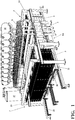
Figure 1 illustrates an elevational perspective view of an embodiment of a multipurpose mould module for expanding and sintering polystyrene according to the present invention; -
Figures 2 and3 illustrate a close perspective view of an embodiment of a multipurpose mould module according to the present invention with half-shells diverged respectively without and with interposition of the panel produced; -
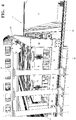
Figure 4 illustrates a perspective view of an embodiment of a multipurpose mould module according to the present invention with half-shells diverged with the supply and unloading modules interlocked thereto; -
Figure 5 illustrates a perspective view of a supply module interlocked to an embodiment of a multipurpose mould module according to the present invention; -
Figure 6 illustrates a perspective view of an unloading module interlocked to an embodiment of a multipurpose according to the present invention; -
Figures 7 and8 illustrate two elevational perspective views of a pairing embodiment of multipurpose mould modules for expanding and sintering polystyrene according to the present invention; -
Figures 9 and10 illustrate perspective views of an embodiment of multipurpose mould modules paired with half-shells diverged respectively without and with interposition of reinforcement designated to complete the panel produced; -
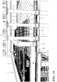
Figure 11 illustrates an elevational perspective view of a supply module interlocked to an embodiment of multipurpose mould modules paired according to the present invention; -
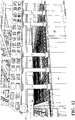
Figures 12 and13 illustrate a perspective view of an embodiment of multipurpose mould modules according to the present invention with half-shells diverged respectively before and after producing a panel. - With reference to such figures, and in particular to
figure 1 , a first multipurpose mould module for expanding and sintering the polystyrene according to the present invention, to which aseparate supply module 3 ofreinforcement trestles 5 on one front and aseparate unloading module 4 of the formedpanels 6 on the opposite front, are interlocked is indicated in its entirety - substantially parallelepiped - withreference number 1A. - All the constituent elements and kinematic mechanisms, unless otherwise specified, must be considered assembled on suitable supporting metal structures, appropriately dimensioned and interconnected to obtain static and dynamic support of the constituent elements, devices and kinematic mechanisms.
- The
mould 1A consists of amould chamber 2 defined by a lower shell 7 (mould) and an upper shell 8 (counter-mould), which - in the illustrated embodiment - have a rectangular perimeter; suitable to be diverged and approached by means ofhydraulic pistons 9, arranged on the two sides free from thesupply 3 and thedischarge 4 modules, as well as tightenable by means ofpins 10 interacting withseats 11 of the bolt-type 12. - The bottom 13 of the
lower shell 7 and the bottom 14 of theupper shell 8 have a network ofholes 15, duly controlled by valves automatically controlled by the computerized logic which controls the whole machine, for the pouring into themould 2 of the EPS beads supplied by a plurality oftanks 16 arranged above the upper shell, for creating the vacuum inside themould 2 by means of apump 17 and for supplying the sintering steam from a suitable installation. - The bottom 13 of the
lower shell 7 is movable, in order to vary the volume of themould chamber 2, by means of a system of hydraulic plungers, not illustrated. - The bottom 13 of the
lower shell 7 is also provided with a plurality of pneumatically actuatedejectable mushrooms 18 which can be displaced both independently and together with the lower bottom 13, together with which they are suitable to translate upon the volume variation of themould chamber 2; the functionality of theejectable mushrooms 18 can be selectively activated or deactivated in the operation of the machine as a function of the kind and type of the product subject of production at that time. - The bottom 13 of the
lower shell 7 and the bottom 14 of theupper shell 8 are suitable to be coated with respective surface-shapedmatrices 19, undulated in the embodiment illustrated infigures 2 and3 , in order to achieve any surface conformation of the extended faces of the formedpanels 6; such matrices can also be located in circumscribed areas of themould chamber 2 and also have a thickness corresponding to the contingent depth of themould chamber 2, to obtain through holes in the formedpanels 6, for example windows and doors in the formedpanels 6 intended to constitute walls (see for examplefigure 13 ). - The
supply module 3 comprises apantograph elevator 20 andinterchangeable supply carriages 21 onguides 22 to the ground for supplying stacks ofreinforcement trestles 5, as well as asupport trolley 23 for thereinforcement trestles 5 sliding onside rails 24, suitable for picking upsingle reinforcement trellis 5 from the top of the stack, for example by means ofmagnets 25, and translating them in succession in thelower shell 7 of themould 2. - On the other hand, the
unloading module 4 comprises apantograph descender 26 andinterchangeable removal carriages 27 on ground guides 28 for removing stacks of mouldedpanels 6, as well as an upperoverhead crane 29 sliding onside rails 30, suitable for picking upmoulded panels 6, for example by means ofsuction cups 31, from thelower shell 7 of themould 2 and move them in succession by stacking them from above on theremoval carriages 27. -
Figures 7 and subsequent figures illustrate twomould modules mould chamber 2, with mutual twinning adaptation by exclusively reducing the shared intermediate edges in the direction of insertion of theplates 5 and removal of the formedpanels 6, without prejudice to providing further components for the functions outlined hereinafter. - Thus, having completed the static description of a preferred embodiment of the multipurpose mould structure for the expansion and sintering of polystyrene obtained according to the present invention, below is the dynamic description, i.e. the operation:
all the automatic functionalities of themodules - The first of these functions is the polyvalent dimensional adjustment of the mould chamber 2:
- in its thickness, by displacing the bottom 13 of the
lower shell 7, by means of the hydraulic devices not illustrated, to which the bottom 13 of thelower shell 7 is interlocked; - in its expansion extension, by coupling two or
more mould modules - in its restriction extension, by inserting - into the mould chamber 2 - elements which are obstructive to the spreading of the beads and to the relative sintering, by means of a perimetral dimensions of the
panel 6 and/or where it is intended to project an opening or through hole into thepanel 6; - in its surface shape, through possible insertion on the bottom 13 of the
lower shell 7 and/or on the bottom 14 of theupper shell 8 of the mould 1, or of themould chamber 2, of dies 19 for shaping the surface of the extended faces of thepanel 6. - If the
panel 6 to be produced is not of the type made of composite material, that is, it is not internally reinforced, or it still does not have strengthening and/or functional elements embedded within the sintered polymeric mass, in other words it is made of pure polystyrene, the production functions of the machine include: - closing the mould 1, by means of the descent of the
upper shell 8 onto thelower shell 7, by means of thehydraulic devices 9; - mutual tightening constraint of the
shells mould chamber 2, by inserting pins for locking theupper shell 8 into therespective seats 11 of thelower shell 7 and relative slide trapping of thebolts 12, suitably driven linearly with any suitable device according to the prior art; - pouring - into the
mould chamber 2 thus tightened - an appropriate amount of EPS beads from thetanks 16, with simultaneous creation of a vacuum within themould chamber 2 by means of thevacuum pump 17, in order to facilitate instantaneous suctioning and pouring of the EPS spherules and relative homogeneous diffusion in the entire volume of themould chamber 2, at the amount required by the desired density in the finished product, as per appropriately programmed computerised logic; - supplying water vapour flows once the delivery of the volume of polystyrene beads for one mole and an appropriate displacement to the
specific panel 6 to be formed have been completed, which produce expansion and sintering of the polystyrene mass; - unclosing the
mould chamber 2 by opening theshells panel 6 formed therein from the bottom 13 of thelower shell 7 by means of the plurality ofejectable mushrooms 18; - translation of the upper
overhead crane 29 for removing thesingle panels 6 formed in the area of theopen mould chamber 2, picking up thepanel 6 formed therein by means of thesuction cups 31 and relative transfer, with deposition apically to the stack ofpanels 6 already formed in the previous operating cycles; - simultaneous descent of a step of panel thickness by the
pantograph descender 26 of theunloading module 4, until the loading of theremoval trolley 27 of the stacks of formedpanels 6 is completed, with ensuing removal on the ground and the arrival - in its place - of a newempty carriage 27 for loading, and so on. - Where, conversely, the
panel 6 to be produced is of the type made of composite material, i.e. internally reinforced, or still integrated withreinforcement trestle 5 and/or strengthening elements and/or functional elements embedded within the sintered polymeric mass, the production functions of the machine are: upstream of those described above: - the
supply module 3 is supplied with a succession of stackedreinforcement trestles 5supply carriages 21, in an appropriate position under the upperoverhead crane 23 for picking up and translating thesingle plates 5; - raising of the stacked
reinforcement trellis 5 to subsequent levels, by means of thepantograph elevator 20, which always positions thetop trestle 5 of the stack at the removal level, hereinafter, after picking up the previous one, until exhaustion and replacement with anew carriage 21 for supplying stackedreinforcement trestles 5; - gripping a
single reinforcement 5 from the top of the stack, by means of themagnets 25, by the upperoverhead crane 23 for picking up and translating thesingle reinforcements 5, relative translation and deposition in thelower shell 7 of the mould 1; - closing the mould 1, by means of the descent of the
upper shell 8 onto thelower shell 7, by means of thehydraulic devices 9; - operating continuation as already described above for non-reinforced panels.
- It is obvious that in alternative embodiments, still falling within the concept solution of the implementation example illustrated above and claimed below, the modular mould structure for expanding and sintering polystyrene according to the present invention, may also be implemented and obtained differently, through equivalent technical and mechanical solutions still falling within the scope of protection illustrated and claimed below;
- As observable from the detailed description of preferred but non-exclusive embodiments above, the modular mould structure for expanding and sintering polystyrene according to the present invention, offers advantages corresponding to the attainment of the preset objects, to which reference shall be made to identify these and other corresponding advantages:
- for this purpose, main reference is made to the object of the invention which is that of obtaining the sintering of reinforced polystyrene panels with the common denominator of having large dimensions, but differentiated by the shape, accessories and dimensions thereof, for obtaining self-referential building prefabricated products for building innovative constructions exclusively obtained using high density sintered reinforced polystyrene panels;
- in this context, the multipurpose mould structure according to the present invention allows to mould high-density reinforced or less sintered polystyrene panels, substantially of any size, thickness, shape and accessorising, which the constructive design and technique of the industry may require;
- all in terms of marked automation, with quick supply of the reinforcement and removal of the product and an equally quick moulding for the immediate positioning of the supply reservoirs of the beads distributed homogeneously over the entire mould area, i.e. without tortuous and/or extended ducts which lengthen moulding times and yields,
-
- 1A)
- first multipurpose mould module
- 1B)
- second multipurpose mould module
- 2)
- mould chamber
- 3)
- supply module
- 4)
- unloading module
- 5)
- reinforcement trellis
- 6)
- panels
- 7)
- lower shell of the mould
- 8)
- upper shell of the mould
- 9)
- mould closing and opening hydraulic plungers
- 10)
- tightening pins
- 11)
- seats for tightening pins
- 12)
- tightening bolts
- 13)
- bottom of the lower shell of the mould
- 14)
- bottom of the upper shell of the mould
- 15)
- holes on the bottom of the shells of the mould
- 16)
- EPS bead tanks
- 17)
- vacuum pump
- 18)
- ejectable mushrooms
- 19)
- surface shaping dies
- 20)
- pantograph elevator of the supply module
- 21)
- reinforcement supply carriages
- 22)
- guides of the reinforcement supply carriages
- 23)
- upper overhead crane for translation of single reinforcements
- 24)
- guide for the upper overhead crane for translation of single reinforcements
- 25)
- magnets of the upper overhead crane, for translation of single reinforcements
- 26)
- pantograph descender of the unloading module
- 27)
- carriages for removing stacks of formed panels
- 28)
- guides for carriages for removing stacks of formed panels
- 29)
- upper overhead crane for removing single formed panels
- 30)
- rails for the upper overhead crane for removing single formed panels
- 31)
- suction cups for the upper overhead crane for removing single formed panels
Claims (12)
- Multipurpose mould structure for the expansion and sintering of polystyrene (eps, polystyrene), for manufacturing prefabricated panels for construction purposes (6), made of reinforced or non-reinforced sintered expanded polystyreneconsisting, when reinforced, of a composite complex obtained by aggregating steel to the sintered expanded polymeric mass, preferably of the high-density type, by embedding - thereinto - typically wire-like/rod-like metal elements preassembled to form a cage (5) made of electrowelded elements, often provided with further metalware such as hinges and/or joining strips and/or the like, characterised in that it comprises at least one mould modular operating unit (1A, 1B) consisting of at least two half-shells (7, 8) with variable geometry and shape to modify the volume, the size and the conformation of the mould compartment or chamber (2), served by a module (3) with mechanisms for supplying (20, 21) and loading (23, 25) the reinforcement means (5) or elements to be embedded into the moulded sintered mass, as well as a module (4) with mechanisms for unloading (21, 31) and removing (26, 27) the moulded panels (6); said operating unit (1A) being designated to be twinned to at least an identical one (1B) to form a single mould compartment or chamber (2) with an area at least twice as large.
- Mould structure according to claim one characterised in that it comprises a mould chamber (2) defined by a lower shell 7 (mould) and by an upper shell 8 (counter-mould) with rectangular perimeter suitable to be diverged and approached by means of hydraulic or pneumatic plungers (9) positioned on two juxtaposed fronts free from the juxtaposed fronts to which the supply module (3) and the unloading module (4) are respectively associated.
- Mould structure according to any one of claims one and two characterised in that the bottom (13) of the lower shell (7) is movable and can be displaced so as to vary the depth of the lower shell (7) and the volume of the mould chamber (2).
- Mould structure according to any one of the preceding claims characterised in that said mould modules (1A, 1B) can be combined with the aim of doubling the mould chamber (2) with mutual twinning adaptation by eliminating the shared intermediate edges in the direction of insertion of the reinforcements (5) by the module for supplying (3) and removing the formed panels (6) by the unloading module (4).
- Mould structure according to any one of the preceding claims characterised in that the bottom (13) of the lower shell (7) is provided with a plurality of ejectable mushrooms (18).
- Mould structure according to any one of the preceding claims characterised in that the bottom (13) of the lower shell (7) is provided with a plurality of ejectable mushrooms that can be arranged both independently and together with the lower bottom (13), alongside which they are suitable to translate upon the variation of the volume of the mould chamber (2).
- Mould structure according to any one of the preceding claims characterised in that the bottom (13) of the lower shell (7) and the bottom (14) of the upper shell (8) have a network of holes (15) subjected to valves for the pouring - into the mould (2) - of the EPS beads sourced from a plurality of tanks (16) arranged over the upper shell (8), for creating the vacuum in the mould structure (2) and for delivering sintering steam.
- Mould structure according to any one of the preceding claims characterised in that the bottom (13) of the lower shell (7) and the bottom (14) of the upper shell (8) can be tightened by means of pins (10) interacting with seats (11) in a bolt-like fashion (12).
- Mould structure according to any one of the preceding claims characterised in that the bottom (13) of the lower shell (7) and the bottom (14) of the upper shell (8) are suitable to be coated with respective dies (19) with surface shape to obtain any surface shape of the extended faces of the formed panels (6).
- Mould structure according to any one of the preceding claims characterised in that such dies (19) are located in circumscribed areas of the mould chamber (2) and have thickness corresponding to the contingent depth of the mould chamber (2) to obtain through holes in the formed panels (6).
- Mould structure according to any one of the preceding claims characterised in that the supply module (3) comprises an elevator (20) for the stacks of reinforcement trellis (5) and interchangeable supply carriages (21) for supplying the stacks of reinforcement trellis (5) as well as a supply carriage (23) for the reinforcement trellis (5) suitable to pick up single reinforcement trellis (5) from the top part of the stack and translate them in succession to the lower shell (7) of the mould (2).
- Mould structure according to any one of the preceding claims characterised in that the unloading module (4) comprises a descender (26) for the moulded panels (6) and interchangeable removal carriages (27) for removing stacks of moulded panels (6) as well as an upper overhead crane (29) suitable to pick up the moulded panels (6) from the lower shell (7) of the mould (2) and translate them in succession stacking them from above on the removal carriages (27).
Applications Claiming Priority (1)
| Application Number | Priority Date | Filing Date | Title |
|---|---|---|---|
| IT201900006761 | 2019-05-13 |
Publications (2)
| Publication Number | Publication Date |
|---|---|
| EP3753701A1 true EP3753701A1 (en) | 2020-12-23 |
| EP3753701B1 EP3753701B1 (en) | 2022-03-23 |
Family
ID=67660722
Family Applications (1)
| Application Number | Title | Priority Date | Filing Date |
|---|---|---|---|
| EP20173846.5A Active EP3753701B1 (en) | 2019-05-13 | 2020-05-11 | Multipurpose mould structure for the expansion and sintering of polystyrene |
Country Status (2)
| Country | Link |
|---|---|
| EP (1) | EP3753701B1 (en) |
| ES (1) | ES2914416T3 (en) |
Citations (4)
| Publication number | Priority date | Publication date | Assignee | Title |
|---|---|---|---|---|
| FR2613663A1 (en) * | 1987-04-10 | 1988-10-14 | Decaudin Bernard | Closed mould which can be adjusted in three dimensions, intended for the expansion of synthetic resins for the manufacture of a sandwich panel |
| WO1997039205A1 (en) * | 1996-04-18 | 1997-10-23 | Structural Technologies, Inc. | Composite skin panels |
| EP1897668A1 (en) * | 2006-09-11 | 2008-03-12 | L&P Swiss Holding Company | Method and system for automatically feeding inserts to a mold and mold |
| WO2016102486A1 (en) | 2014-12-24 | 2016-06-30 | Angelo Candiracci | Modular moulding structure for expanding and sintering polystyrene |
-
2020
- 2020-05-11 ES ES20173846T patent/ES2914416T3/en active Active
- 2020-05-11 EP EP20173846.5A patent/EP3753701B1/en active Active
Patent Citations (4)
| Publication number | Priority date | Publication date | Assignee | Title |
|---|---|---|---|---|
| FR2613663A1 (en) * | 1987-04-10 | 1988-10-14 | Decaudin Bernard | Closed mould which can be adjusted in three dimensions, intended for the expansion of synthetic resins for the manufacture of a sandwich panel |
| WO1997039205A1 (en) * | 1996-04-18 | 1997-10-23 | Structural Technologies, Inc. | Composite skin panels |
| EP1897668A1 (en) * | 2006-09-11 | 2008-03-12 | L&P Swiss Holding Company | Method and system for automatically feeding inserts to a mold and mold |
| WO2016102486A1 (en) | 2014-12-24 | 2016-06-30 | Angelo Candiracci | Modular moulding structure for expanding and sintering polystyrene |
Also Published As
| Publication number | Publication date |
|---|---|
| EP3753701B1 (en) | 2022-03-23 |
| ES2914416T3 (en) | 2022-06-10 |
Similar Documents
| Publication | Publication Date | Title |
|---|---|---|
| US8940383B2 (en) | Blocks of wood agglomerate | |
| US5002817A (en) | Form liner and method for forming concrete panels with artistic relief patterns | |
| CA1187268A (en) | Prefabricated building elements and construction | |
| JP2003528232A (en) | Composite building materials | |
| US8252221B2 (en) | Compacting techniques for forming lightweight concrete building blocks | |
| US20020109263A1 (en) | Process for preparing composite molded articles by multicomponent injection molding | |
| US5806264A (en) | Multi-cellular wall structure | |
| US20030079438A1 (en) | Precast modular building panel and vertically oriented method of manufacturing same | |
| KR20150079900A (en) | Mold, control means, method and installation for producing a preferably fiber-reinforced plastic component | |
| EP3753701B1 (en) | Multipurpose mould structure for the expansion and sintering of polystyrene | |
| JP2001105421A (en) | Curing method and manufacturing system for precast concrete members | |
| US6547547B2 (en) | Apparatus for molding composite foam molding element | |
| EP3237168B1 (en) | Modular moulding structure for expanding and sintering polystyrene | |
| CN113454301B (en) | Building energy-saving three-dimensional panel, equipment and manufacturing method thereof | |
| CN113021609B (en) | Production device for concrete prefabricated part | |
| KR20010042467A (en) | Pre-cast concrete walling system | |
| US20240051197A1 (en) | Device and method for manufacturing board-like insulating elements | |
| EP0885706B1 (en) | Apparatus and method for making panels | |
| WO2016062697A1 (en) | Method for producing panels, prefabricated products and frames for the furnishing industry and products obtained with such method | |
| AU2012391049A1 (en) | Method of making a panel | |
| EP2095927B1 (en) | Method for producing continuous expanded polystyrene foam parts | |
| WO2000047381A1 (en) | Formers and methods of casting bodies, particularly concrete bodies, using the formers | |
| IT9067598A1 (en) | PROCEDURE FOR THE CREATION OF CABLE BODIES IN THERMOPLASTIC MATERIAL AND PRODUCTS SO OBTAINED | |
| CN121871002A (en) | Fireproof polyurethane foam material and preparation method thereof | |
| CN108698270B (en) | Apparatus and process for manufacturing a modular formwork building element and formwork element so manufactured |
Legal Events
| Date | Code | Title | Description |
|---|---|---|---|
| PUAI | Public reference made under article 153(3) epc to a published international application that has entered the european phase |
Free format text: ORIGINAL CODE: 0009012 |
|
| STAA | Information on the status of an ep patent application or granted ep patent |
Free format text: STATUS: THE APPLICATION HAS BEEN PUBLISHED |
|
| AK | Designated contracting states |
Kind code of ref document: A1 Designated state(s): AL AT BE BG CH CY CZ DE DK EE ES FI FR GB GR HR HU IE IS IT LI LT LU LV MC MK MT NL NO PL PT RO RS SE SI SK SM TR |
|
| AX | Request for extension of the european patent |
Extension state: BA ME |
|
| STAA | Information on the status of an ep patent application or granted ep patent |
Free format text: STATUS: REQUEST FOR EXAMINATION WAS MADE |
|
| 17P | Request for examination filed |
Effective date: 20210423 |
|
| RBV | Designated contracting states (corrected) |
Designated state(s): AL AT BE BG CH CY CZ DE DK EE ES FI FR GB GR HR HU IE IS IT LI LT LU LV MC MK MT NL NO PL PT RO RS SE SI SK SM TR |
|
| GRAP | Despatch of communication of intention to grant a patent |
Free format text: ORIGINAL CODE: EPIDOSNIGR1 |
|
| STAA | Information on the status of an ep patent application or granted ep patent |
Free format text: STATUS: GRANT OF PATENT IS INTENDED |
|
| INTG | Intention to grant announced |
Effective date: 20211013 |
|
| GRAS | Grant fee paid |
Free format text: ORIGINAL CODE: EPIDOSNIGR3 |
|
| GRAA | (expected) grant |
Free format text: ORIGINAL CODE: 0009210 |
|
| STAA | Information on the status of an ep patent application or granted ep patent |
Free format text: STATUS: THE PATENT HAS BEEN GRANTED |
|
| AK | Designated contracting states |
Kind code of ref document: B1 Designated state(s): AL AT BE BG CH CY CZ DE DK EE ES FI FR GB GR HR HU IE IS IT LI LT LU LV MC MK MT NL NO PL PT RO RS SE SI SK SM TR |
|
| REG | Reference to a national code |
Ref country code: GB Ref legal event code: FG4D |
|
| REG | Reference to a national code |
Ref country code: CH Ref legal event code: EP |
|
| REG | Reference to a national code |
Ref country code: IE Ref legal event code: FG4D |
|
| REG | Reference to a national code |
Ref country code: DE Ref legal event code: R096 Ref document number: 602020002288 Country of ref document: DE |
|
| REG | Reference to a national code |
Ref country code: AT Ref legal event code: REF Ref document number: 1477140 Country of ref document: AT Kind code of ref document: T Effective date: 20220415 |
|
| REG | Reference to a national code |
Ref country code: ES Ref legal event code: FG2A Ref document number: 2914416 Country of ref document: ES Kind code of ref document: T3 Effective date: 20220610 |
|
| REG | Reference to a national code |
Ref country code: LT Ref legal event code: MG9D |
|
| REG | Reference to a national code |
Ref country code: NL Ref legal event code: MP Effective date: 20220323 |
|
| PG25 | Lapsed in a contracting state [announced via postgrant information from national office to epo] |
Ref country code: SE Free format text: LAPSE BECAUSE OF FAILURE TO SUBMIT A TRANSLATION OF THE DESCRIPTION OR TO PAY THE FEE WITHIN THE PRESCRIBED TIME-LIMIT Effective date: 20220323 Ref country code: RS Free format text: LAPSE BECAUSE OF FAILURE TO SUBMIT A TRANSLATION OF THE DESCRIPTION OR TO PAY THE FEE WITHIN THE PRESCRIBED TIME-LIMIT Effective date: 20220323 Ref country code: NO Free format text: LAPSE BECAUSE OF FAILURE TO SUBMIT A TRANSLATION OF THE DESCRIPTION OR TO PAY THE FEE WITHIN THE PRESCRIBED TIME-LIMIT Effective date: 20220623 Ref country code: LT Free format text: LAPSE BECAUSE OF FAILURE TO SUBMIT A TRANSLATION OF THE DESCRIPTION OR TO PAY THE FEE WITHIN THE PRESCRIBED TIME-LIMIT Effective date: 20220323 Ref country code: HR Free format text: LAPSE BECAUSE OF FAILURE TO SUBMIT A TRANSLATION OF THE DESCRIPTION OR TO PAY THE FEE WITHIN THE PRESCRIBED TIME-LIMIT Effective date: 20220323 Ref country code: BG Free format text: LAPSE BECAUSE OF FAILURE TO SUBMIT A TRANSLATION OF THE DESCRIPTION OR TO PAY THE FEE WITHIN THE PRESCRIBED TIME-LIMIT Effective date: 20220623 |
|
| PG25 | Lapsed in a contracting state [announced via postgrant information from national office to epo] |
Ref country code: LV Free format text: LAPSE BECAUSE OF FAILURE TO SUBMIT A TRANSLATION OF THE DESCRIPTION OR TO PAY THE FEE WITHIN THE PRESCRIBED TIME-LIMIT Effective date: 20220323 Ref country code: GR Free format text: LAPSE BECAUSE OF FAILURE TO SUBMIT A TRANSLATION OF THE DESCRIPTION OR TO PAY THE FEE WITHIN THE PRESCRIBED TIME-LIMIT Effective date: 20220624 Ref country code: FI Free format text: LAPSE BECAUSE OF FAILURE TO SUBMIT A TRANSLATION OF THE DESCRIPTION OR TO PAY THE FEE WITHIN THE PRESCRIBED TIME-LIMIT Effective date: 20220323 |
|
| PG25 | Lapsed in a contracting state [announced via postgrant information from national office to epo] |
Ref country code: NL Free format text: LAPSE BECAUSE OF FAILURE TO SUBMIT A TRANSLATION OF THE DESCRIPTION OR TO PAY THE FEE WITHIN THE PRESCRIBED TIME-LIMIT Effective date: 20220323 |
|
| PG25 | Lapsed in a contracting state [announced via postgrant information from national office to epo] |
Ref country code: SM Free format text: LAPSE BECAUSE OF FAILURE TO SUBMIT A TRANSLATION OF THE DESCRIPTION OR TO PAY THE FEE WITHIN THE PRESCRIBED TIME-LIMIT Effective date: 20220323 Ref country code: SK Free format text: LAPSE BECAUSE OF FAILURE TO SUBMIT A TRANSLATION OF THE DESCRIPTION OR TO PAY THE FEE WITHIN THE PRESCRIBED TIME-LIMIT Effective date: 20220323 Ref country code: RO Free format text: LAPSE BECAUSE OF FAILURE TO SUBMIT A TRANSLATION OF THE DESCRIPTION OR TO PAY THE FEE WITHIN THE PRESCRIBED TIME-LIMIT Effective date: 20220323 Ref country code: PT Free format text: LAPSE BECAUSE OF FAILURE TO SUBMIT A TRANSLATION OF THE DESCRIPTION OR TO PAY THE FEE WITHIN THE PRESCRIBED TIME-LIMIT Effective date: 20220725 Ref country code: EE Free format text: LAPSE BECAUSE OF FAILURE TO SUBMIT A TRANSLATION OF THE DESCRIPTION OR TO PAY THE FEE WITHIN THE PRESCRIBED TIME-LIMIT Effective date: 20220323 Ref country code: CZ Free format text: LAPSE BECAUSE OF FAILURE TO SUBMIT A TRANSLATION OF THE DESCRIPTION OR TO PAY THE FEE WITHIN THE PRESCRIBED TIME-LIMIT Effective date: 20220323 |
|
| PG25 | Lapsed in a contracting state [announced via postgrant information from national office to epo] |
Ref country code: PL Free format text: LAPSE BECAUSE OF FAILURE TO SUBMIT A TRANSLATION OF THE DESCRIPTION OR TO PAY THE FEE WITHIN THE PRESCRIBED TIME-LIMIT Effective date: 20220323 Ref country code: IS Free format text: LAPSE BECAUSE OF FAILURE TO SUBMIT A TRANSLATION OF THE DESCRIPTION OR TO PAY THE FEE WITHIN THE PRESCRIBED TIME-LIMIT Effective date: 20220723 Ref country code: AL Free format text: LAPSE BECAUSE OF FAILURE TO SUBMIT A TRANSLATION OF THE DESCRIPTION OR TO PAY THE FEE WITHIN THE PRESCRIBED TIME-LIMIT Effective date: 20220323 |
|
| REG | Reference to a national code |
Ref country code: DE Ref legal event code: R097 Ref document number: 602020002288 Country of ref document: DE |
|
| REG | Reference to a national code |
Ref country code: BE Ref legal event code: MM Effective date: 20220531 |
|
| PLBE | No opposition filed within time limit |
Free format text: ORIGINAL CODE: 0009261 |
|
| STAA | Information on the status of an ep patent application or granted ep patent |
Free format text: STATUS: NO OPPOSITION FILED WITHIN TIME LIMIT |
|
| PG25 | Lapsed in a contracting state [announced via postgrant information from national office to epo] |
Ref country code: MC Free format text: LAPSE BECAUSE OF FAILURE TO SUBMIT A TRANSLATION OF THE DESCRIPTION OR TO PAY THE FEE WITHIN THE PRESCRIBED TIME-LIMIT Effective date: 20220323 Ref country code: LU Free format text: LAPSE BECAUSE OF NON-PAYMENT OF DUE FEES Effective date: 20220511 Ref country code: DK Free format text: LAPSE BECAUSE OF FAILURE TO SUBMIT A TRANSLATION OF THE DESCRIPTION OR TO PAY THE FEE WITHIN THE PRESCRIBED TIME-LIMIT Effective date: 20220323 |
|
| 26N | No opposition filed |
Effective date: 20230102 |
|
| PG25 | Lapsed in a contracting state [announced via postgrant information from national office to epo] |
Ref country code: IE Free format text: LAPSE BECAUSE OF NON-PAYMENT OF DUE FEES Effective date: 20220511 |
|
| PG25 | Lapsed in a contracting state [announced via postgrant information from national office to epo] |
Ref country code: SI Free format text: LAPSE BECAUSE OF FAILURE TO SUBMIT A TRANSLATION OF THE DESCRIPTION OR TO PAY THE FEE WITHIN THE PRESCRIBED TIME-LIMIT Effective date: 20220323 Ref country code: BE Free format text: LAPSE BECAUSE OF NON-PAYMENT OF DUE FEES Effective date: 20220531 |
|
| P01 | Opt-out of the competence of the unified patent court (upc) registered |
Effective date: 20230525 |
|
| PGFP | Annual fee paid to national office [announced via postgrant information from national office to epo] |
Ref country code: IT Payment date: 20230531 Year of fee payment: 4 Ref country code: FR Payment date: 20230512 Year of fee payment: 4 Ref country code: ES Payment date: 20230605 Year of fee payment: 4 Ref country code: DE Payment date: 20230524 Year of fee payment: 4 Ref country code: CH Payment date: 20230602 Year of fee payment: 4 |
|
| PG25 | Lapsed in a contracting state [announced via postgrant information from national office to epo] |
Ref country code: MK Free format text: LAPSE BECAUSE OF FAILURE TO SUBMIT A TRANSLATION OF THE DESCRIPTION OR TO PAY THE FEE WITHIN THE PRESCRIBED TIME-LIMIT Effective date: 20220323 Ref country code: CY Free format text: LAPSE BECAUSE OF FAILURE TO SUBMIT A TRANSLATION OF THE DESCRIPTION OR TO PAY THE FEE WITHIN THE PRESCRIBED TIME-LIMIT Effective date: 20220323 |
|
| PG25 | Lapsed in a contracting state [announced via postgrant information from national office to epo] |
Ref country code: HU Free format text: LAPSE BECAUSE OF FAILURE TO SUBMIT A TRANSLATION OF THE DESCRIPTION OR TO PAY THE FEE WITHIN THE PRESCRIBED TIME-LIMIT; INVALID AB INITIO Effective date: 20200511 |
|
| REG | Reference to a national code |
Ref country code: AT Ref legal event code: UEP Ref document number: 1477140 Country of ref document: AT Kind code of ref document: T Effective date: 20220323 |
|
| PG25 | Lapsed in a contracting state [announced via postgrant information from national office to epo] |
Ref country code: MT Free format text: LAPSE BECAUSE OF FAILURE TO SUBMIT A TRANSLATION OF THE DESCRIPTION OR TO PAY THE FEE WITHIN THE PRESCRIBED TIME-LIMIT Effective date: 20220323 |
|
| REG | Reference to a national code |
Ref country code: DE Ref legal event code: R119 Ref document number: 602020002288 Country of ref document: DE |
|
| REG | Reference to a national code |
Ref country code: CH Ref legal event code: PL |
|
| GBPC | Gb: european patent ceased through non-payment of renewal fee |
Effective date: 20240511 |
|
| PG25 | Lapsed in a contracting state [announced via postgrant information from national office to epo] |
Ref country code: CH Free format text: LAPSE BECAUSE OF NON-PAYMENT OF DUE FEES Effective date: 20240531 |
|
| PG25 | Lapsed in a contracting state [announced via postgrant information from national office to epo] |
Ref country code: DE Free format text: LAPSE BECAUSE OF NON-PAYMENT OF DUE FEES Effective date: 20241203 |
|
| PG25 | Lapsed in a contracting state [announced via postgrant information from national office to epo] |
Ref country code: FR Free format text: LAPSE BECAUSE OF NON-PAYMENT OF DUE FEES Effective date: 20240531 |
|
| PG25 | Lapsed in a contracting state [announced via postgrant information from national office to epo] |
Ref country code: IT Free format text: LAPSE BECAUSE OF NON-PAYMENT OF DUE FEES Effective date: 20240511 Ref country code: GB Free format text: LAPSE BECAUSE OF NON-PAYMENT OF DUE FEES Effective date: 20240511 |
|
| REG | Reference to a national code |
Ref country code: ES Ref legal event code: FD2A Effective date: 20250626 |
|
| PG25 | Lapsed in a contracting state [announced via postgrant information from national office to epo] |
Ref country code: ES Free format text: LAPSE BECAUSE OF NON-PAYMENT OF DUE FEES Effective date: 20240512 |
|
| PGFP | Annual fee paid to national office [announced via postgrant information from national office to epo] |
Ref country code: AT Payment date: 20250721 Year of fee payment: 5 |
|
| PG25 | Lapsed in a contracting state [announced via postgrant information from national office to epo] |
Ref country code: TR Free format text: LAPSE BECAUSE OF FAILURE TO SUBMIT A TRANSLATION OF THE DESCRIPTION OR TO PAY THE FEE WITHIN THE PRESCRIBED TIME-LIMIT Effective date: 20220323 |
|
| PG25 | Lapsed in a contracting state [announced via postgrant information from national office to epo] |
Ref country code: AT Free format text: LAPSE BECAUSE OF NON-PAYMENT OF DUE FEES Effective date: 20250511 |
|
| REG | Reference to a national code |
Ref country code: AT Ref legal event code: MM01 Ref document number: 1477140 Country of ref document: AT Kind code of ref document: T Effective date: 20250511 |