EP3753683B1 - Verfahren und system zur erzeugung eines roboterprogramms für industrielle beschichtung - Google Patents
Verfahren und system zur erzeugung eines roboterprogramms für industrielle beschichtung Download PDFInfo
- Publication number
- EP3753683B1 EP3753683B1 EP19180630.6A EP19180630A EP3753683B1 EP 3753683 B1 EP3753683 B1 EP 3753683B1 EP 19180630 A EP19180630 A EP 19180630A EP 3753683 B1 EP3753683 B1 EP 3753683B1
- Authority
- EP
- European Patent Office
- Prior art keywords
- coating
- robotic
- tuples
- thickness
- given
- Prior art date
- Legal status (The legal status is an assumption and is not a legal conclusion. Google has not performed a legal analysis and makes no representation as to the accuracy of the status listed.)
- Active
Links
Images


Classifications
-
- B—PERFORMING OPERATIONS; TRANSPORTING
- B25—HAND TOOLS; PORTABLE POWER-DRIVEN TOOLS; MANIPULATORS
- B25J—MANIPULATORS; CHAMBERS PROVIDED WITH MANIPULATION DEVICES
- B25J9/00—Programme-controlled manipulators
- B25J9/16—Programme controls
- B25J9/1674—Programme controls characterised by safety, monitoring, diagnostic
- B25J9/1676—Avoiding collision or forbidden zones
-
- B—PERFORMING OPERATIONS; TRANSPORTING
- B25—HAND TOOLS; PORTABLE POWER-DRIVEN TOOLS; MANIPULATORS
- B25J—MANIPULATORS; CHAMBERS PROVIDED WITH MANIPULATION DEVICES
- B25J9/00—Programme-controlled manipulators
- B25J9/16—Programme controls
- B25J9/1656—Programme controls characterised by programming, planning systems for manipulators
- B25J9/1664—Programme controls characterised by programming, planning systems for manipulators characterised by motion, path, trajectory planning
-
- B—PERFORMING OPERATIONS; TRANSPORTING
- B05—SPRAYING OR ATOMISING IN GENERAL; APPLYING FLUENT MATERIALS TO SURFACES, IN GENERAL
- B05B—SPRAYING APPARATUS; ATOMISING APPARATUS; NOZZLES
- B05B15/00—Details of spraying plant or spraying apparatus not otherwise provided for; Accessories
- B05B15/70—Arrangements for moving spray heads automatically to or from the working position
-
- B—PERFORMING OPERATIONS; TRANSPORTING
- B05—SPRAYING OR ATOMISING IN GENERAL; APPLYING FLUENT MATERIALS TO SURFACES, IN GENERAL
- B05B—SPRAYING APPARATUS; ATOMISING APPARATUS; NOZZLES
- B05B12/00—Arrangements for controlling delivery; Arrangements for controlling the spray area
- B05B12/08—Arrangements for controlling delivery; Arrangements for controlling the spray area responsive to condition of liquid or other fluent material to be discharged, of ambient medium or of target ; responsive to condition of spray devices or of supply means, e.g. pipes, pumps or their drive means
- B05B12/084—Arrangements for controlling delivery; Arrangements for controlling the spray area responsive to condition of liquid or other fluent material to be discharged, of ambient medium or of target ; responsive to condition of spray devices or of supply means, e.g. pipes, pumps or their drive means responsive to condition of liquid or other fluent material already sprayed on the target, e.g. coating thickness, weight or pattern
-
- B—PERFORMING OPERATIONS; TRANSPORTING
- B25—HAND TOOLS; PORTABLE POWER-DRIVEN TOOLS; MANIPULATORS
- B25J—MANIPULATORS; CHAMBERS PROVIDED WITH MANIPULATION DEVICES
- B25J11/00—Manipulators not otherwise provided for
- B25J11/0075—Manipulators for painting or coating
-
- B—PERFORMING OPERATIONS; TRANSPORTING
- B25—HAND TOOLS; PORTABLE POWER-DRIVEN TOOLS; MANIPULATORS
- B25J—MANIPULATORS; CHAMBERS PROVIDED WITH MANIPULATION DEVICES
- B25J9/00—Programme-controlled manipulators
- B25J9/16—Programme controls
- B25J9/1656—Programme controls characterised by programming, planning systems for manipulators
- B25J9/1664—Programme controls characterised by programming, planning systems for manipulators characterised by motion, path, trajectory planning
- B25J9/1666—Avoiding collision or forbidden zones
-
- B—PERFORMING OPERATIONS; TRANSPORTING
- B25—HAND TOOLS; PORTABLE POWER-DRIVEN TOOLS; MANIPULATORS
- B25J—MANIPULATORS; CHAMBERS PROVIDED WITH MANIPULATION DEVICES
- B25J9/00—Programme-controlled manipulators
- B25J9/16—Programme controls
- B25J9/1656—Programme controls characterised by programming, planning systems for manipulators
- B25J9/1671—Programme controls characterised by programming, planning systems for manipulators characterised by simulation, either to verify existing program or to create and verify new program, CAD/CAM oriented, graphic oriented programming systems
-
- B—PERFORMING OPERATIONS; TRANSPORTING
- B25—HAND TOOLS; PORTABLE POWER-DRIVEN TOOLS; MANIPULATORS
- B25J—MANIPULATORS; CHAMBERS PROVIDED WITH MANIPULATION DEVICES
- B25J9/00—Programme-controlled manipulators
- B25J9/16—Programme controls
- B25J9/1679—Programme controls characterised by the tasks executed
-
- G—PHYSICS
- G06—COMPUTING OR CALCULATING; COUNTING
- G06F—ELECTRIC DIGITAL DATA PROCESSING
- G06F30/00—Computer-aided design [CAD]
- G06F30/20—Design optimisation, verification or simulation
- G06F30/27—Design optimisation, verification or simulation using machine learning, e.g. artificial intelligence, neural networks, support vector machines [SVM] or training a model
-
- G—PHYSICS
- G06—COMPUTING OR CALCULATING; COUNTING
- G06N—COMPUTING ARRANGEMENTS BASED ON SPECIFIC COMPUTATIONAL MODELS
- G06N20/00—Machine learning
-
- G—PHYSICS
- G05—CONTROLLING; REGULATING
- G05B—CONTROL OR REGULATING SYSTEMS IN GENERAL; FUNCTIONAL ELEMENTS OF SUCH SYSTEMS; MONITORING OR TESTING ARRANGEMENTS FOR SUCH SYSTEMS OR ELEMENTS
- G05B2219/00—Program-control systems
- G05B2219/30—Nc systems
- G05B2219/36—Nc in input of data, input key till input tape
- G05B2219/36252—Generate machining program based on a simulation to optimize a machine parameter
-
- G—PHYSICS
- G05—CONTROLLING; REGULATING
- G05B—CONTROL OR REGULATING SYSTEMS IN GENERAL; FUNCTIONAL ELEMENTS OF SUCH SYSTEMS; MONITORING OR TESTING ARRANGEMENTS FOR SUCH SYSTEMS OR ELEMENTS
- G05B2219/00—Program-control systems
- G05B2219/30—Nc systems
- G05B2219/45—Nc applications
- G05B2219/45013—Spraying, coating, painting
Definitions
- the present disclosure is directed, in general, to computer-aided design, visualization, and manufacturing (“CAD”) systems, product lifecycle management (“PLM”) systems, product data management (“PDM”) systems, and similar systems, that manage data for products and other items (collectively, “Product Data Management” systems or PDM systems). More specifically, the disclosure is directed to production environment simulation.
- CAD computer-aided design, visualization, and manufacturing
- PLM product lifecycle management
- PDM product data management
- PDM product data management
- the process of applying coating materials on surfaces of objects is a common operation in a large variety of industrial processes.
- coating may denote either the verb, i.e. the operation of applying coating material, e.g. by spraying, or the noun, i.e. the coating material itself.
- a “coating material”, or simply a “coating” is a layer of a substance applied over an object surface, for example for protection, functional and/or decoration purposes.
- coating materials applied to base materials may be used to provide properties not inherent in the base, including corrosion, wear-resistance, conductivity, color, solderability and others.
- coating materials are paints, lacquers, metal platings, thermal-barrier coating materials, anti-corrosion coating materials and other types of protective, functional or decorative coating materials.
- coating may also denote additive manufacturing where a three-dimensional ("3D") industrial object is built by adding layer-upon-layer of material, e.g. the coating material.
- 3D three-dimensional
- the amount of coating applied on a product object surface that is, the coating thickness, often contributes to the product quality standard.
- a coating operation is required to meet certain levels in terms of the achieved thicknesses and uniformity levels of the coating layer.
- coating operations are mostly performed by coating guns which are mounted on robots.
- US9811074B1 relates to the optimization of robot control programs in physics-based simulated environment.
- US2017032060A1 relates to calculating thickness of applied coating material.
- Embodiments enable automatic generation of a collision-free coating robotic program with the desired coating thickness coverage.
- Embodiments enable reaching a faster, accurate and reliable solution to the coating industry quality requirements with reduced complexity, costs and efforts.
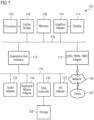
- FIG. 1 illustrates a block diagram of a data processing system 100 in which an embodiment can be implemented, for example as a PDM system particularly configured by software or otherwise to perform the processes as described herein, and in particular as each one of a plurality of interconnected and communicating systems as described herein.
- the data processing system 100 illustrated can include a processor 102 connected to a level two cache/bridge 104, which is connected in turn to a local system bus 106.
- Local system bus 106 may be, for example, a peripheral component interconnect (PCI) architecture bus.
- PCI peripheral component interconnect
- Also connected to local system bus in the illustrated example are a main memory 108 and a graphics adapter 110.
- the graphics adapter 110 may be connected to display 111.
- Peripherals such as local area network (LAN) / Wide Area Network / Wireless (e.g. WiFi) adapter 112, may also be connected to local system bus 106.
- Expansion bus interface 114 connects local system bus 106 to input/output (I/O) bus 116.
- I/O bus 116 is connected to keyboard/mouse adapter 118, disk controller 120, and I/O adapter 122.
- Disk controller 120 can be connected to a storage 126, which can be any suitable machine usable or machine readable storage medium, including but are not limited to nonvolatile, hard-coded type mediums such as read only memories (ROMs) or erasable, electrically programmable read only memories (EEPROMs), magnetic tape storage, and user-recordable type mediums such as floppy disks, hard disk drives and compact disk read only memories (CD-ROMs) or digital versatile disks (DVDs), and other known optical, electrical, or magnetic storage devices.
- ROMs read only memories
- EEPROMs electrically programmable read only memories
- CD-ROMs compact disk read only memories
- DVDs digital versatile disks
- Audio adapter 124 Also connected to I/O bus 116 in the example shown is audio adapter 124, to which speakers (not shown) may be connected for playing sounds.
- Keyboard/mouse adapter 118 provides a connection for a pointing device (not shown), such as a mouse, trackball, trackpointer, touchscreen, etc.
- a data processing system in accordance with an embodiment of the present disclosure can include an operating system employing a graphical user interface.
- the operating system permits multiple display windows to be presented in the graphical user interface simultaneously, with each display window providing an interface to a different application or to a different instance of the same application.
- a cursor in the graphical user interface may be manipulated by a user through the pointing device. The position of the cursor may be changed and/or an event, such as clicking a mouse button, generated to actuate a desired response.
- One of various commercial operating systems such as a version of Microsoft Windows TM , a product of Microsoft Corporation located in Redmond, Wash. may be employed if suitably modified.
- the operating system is modified or created in accordance with the present disclosure as described.
- LAN/ WAN/Wireless adapter 112 can be connected to a network 130 (not a part of data processing system 100), which can be any public or private data processing system network or combination of networks, as known to those of skill in the art, including the Internet.
- Data processing system 100 can communicate over network 130 with server system 140, which is also not part of data processing system 100, but can be implemented, for example, as a separate data processing system 100.
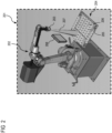
- Figure 2 illustrates a schematic view of an industrial robot with a coating dispersion object mounted on its coating gun nozzle for generating a coating robotic program in accordance with disclosed embodiments.
- Figure 2 it is shown a virtual representation of an industrial sub-cell 201 and a virtual representation of an industrial robot 202 with a coating gun 203 applying coating material on a surface 204 of an industrial object.
- an industrial sub-cell we indicate an industrial cell or any portion of the industrial cell or any 3D environment around a robot 202 which may also include possible obstacles and/or forbidden volumes for detecting unallowed collisions with the robot.
- an obstacle 208 is shown, a collision between the robot 202 and the obstacle 208 is herein denoted as “unallowed” collision.
- unallowed collision is herein used for clarifications purposes to distinguish such type of collision from the other types of collisions to be detected by a collision detection engine for coating calculation purposes as discussed in detail in a subsequent section.
- the "coating" collisions are detected between 3D elements (not shown) of a coating dispersion object 207 and elements 205, 206 of the object surface 204.
- the 3D coating dispersion object 207 is composed of a plurality of 3D entities (not shown) each one having an associated coating dispersion value for calculating the applied coating thickness via the collision detection engine as discussed in detail in a subsequent section.
- coating material is applied by a coating gun 203 on the object surface 204.
- one or more relevant surface areas to be coated are selected, and a mesh representation is generated for the selected surface areas.
- a polygon mesh comprises a collection of vertices 205, edges, and surface sub-elements 206 (e.g. usually triangles) defining the shape of a polyhedral object in 3D computer graphics.
- the resulting mesh geometry is like the geometry of the surface of the original object, and the mesh geometry comprises several mesh sub-elements herein also called mesh-points.
- each sub-element of the mesh is a representation of a sub-element on the part/object surface.
- the density of the mesh points depends on the desired level of accuracy and the surface shape.
- the mesh density may also depend on the used spraying techniques; for example, laser paint spraying may require higher mesh element density than, for example, traditional non-laser paint gun spraying techniques.
- the coating dispersion object 207 is mounted on the coating gun 203 for emulating coating behavior of the coating gun 203.
- the coating dispersion object 207 represents the coating behavior of a given gun and/or of a given brush for the same given gun for a given coating material having certain physical properties, e.g. certain density and certain specific gravity.
- the given coat dispersion object 207 enables calculating the coating thickness applied on a surface while considering different mutual positions (e.g. different distances and/or angles within certain ranges) between the coating gun and the object surface.
- different mutual positions e.g. different distances and/or angles within certain ranges
- FIG. 3 illustrates possible different examples of coating guns 301 to be mounted on a robotic head.
- Each coating gun 301 has at least one corresponding coating dispersion object (not shown) for a given coating material type.
- Each coating gun may have several different coating dispersion objects when several brushes are used and when several applied angles above a certain threshold are to be considered.
- the coating dispersion object received as input for coating calculation purposes may be generated with numerous different techniques, including but not limited to the following examples: coating dispersion objects may be generated departing from a collection of measured real thickness footprints of coating material applied on real test surfaces by given coating guns and/or brushes as disclosed in US patent application with Application Number 14/809,343 ;
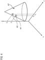
- FIG 4 illustrates a schematic view of a coating dispersion object 407 in accordance with disclosed embodiments.
- the coating dispersion object 407 is composed by a plurality of 3D entities each one with a corresponding coating dispersion value for coating calculation purposes.
- two 3D entities 401, 402 are shown with their corresponding (X,Y,Z) coordinates.
- the coating dispersion object 407 may be generated via a function trained by a machine learning ("ML") algorithm.
- the training data are organized in input and output data where the output training data is related to the input training data.
- the input training data includes robotic gun information (e.g. type of coating gun, type of brush, index, angle and/or index of the coating dispersion object when supporting several different coating dispersion objects in a single ML module) and physical property information of the coating material and the output training data includes (X,Y,Z) coordinates of the 3D entities 401, 402 of the coating dispersion object 407 and their corresponding coating dispersion values (not shown).
- a corresponding function for generating the coating dispersion object may conveniently be trained.
- model of the coating dispersion object is generated as output by applying the trained function to input data for example including information received on the robotic gun and on the coating material desired.
- Figure 5 illustrates a schematic view of a part surface with surface elements 501-510 and corresponding desired coating thickness ranges in accordance with a disclosed embodiment.
- FIG. 5 Assume in Figure 5 is shown a representation of a surface 500 of an industrial object, for example a part of a car over which coating is to be applied for example by spraying.
- a mesh of the surface 500 is created by selecting relevant surface elements 501-510 and by creating a mesh (not shown) for each surface element.
- the mesh geometry is similar to the surface element geometry and is composed of a plurality of mesh elements (e.g. point, edge, vertexes and faces), often called mesh points.
- each point of the mesh represents a point on the corresponding part surface element 502 and it is herein denoted as point or sub-element of the surface element.
- FIG. 5 are shown examples of values of desired coating thickness ranges given in mm for each surface element 501-510.
- a desired coating thickness range of 9-10 mm is given.
- the given range of 9-10 mm for the element 501 may have different meanings and corresponding requirements.
- the desired coating thickness may be required to be constant so that any constant value between 9 and 10 mm is considered a valid coverage thickness range.
- the desired thickness may be any variable value between 9 and 10 mm so that for example a thickness coverage with some sub-areas with a thickness of 9.1 mm and other sub-areas with a thickness of 9.5 mm is to be considered valid coverage.
- a delta value is given to specify what is the acceptable maximum value difference between points of the same surface element 501 or across different surface elements 501-510. For example, if a selected maximum delta value of 1 mm for elements 501, 502 is given, it is acceptable to have points with thickness 9 mm and other points with thickness 10 mm but it is not valid to have points with thickness 9 mm in the first element 501 and points with thickness 11 mm in the second element 501.
- the thickness the coating material applied to the surface 204, 500 is calculated via simulation with a collision detection engine.
- the collision set to be detected for thickness calculation purposes is being defined between the following two groups of entities: the mesh points of the part surface 204 and the 3D entities of the coating dispersion objects 401, 402.
- a robotic program of the coating path operation is simulated via a 3D virtual environment software.
- the robotic motion planning module for the simulation may be for example based on one of the following modules:
- the coating dispersion object 207 is mounted on top of the robot's coating gun 203 for coating calculation purposes so that while the robot is moving it collides with certain mesh points of the part surface 204.
- the dynamic collision detection engine reports which collision pairs are detected (mesh point vs. 3D object entity).
- the thickness value is then calculated with the coating dispersion value of the 3D object entity involved in the robot collision.
- the calculated thickness is then added to the collided mesh point thickness.
- each mesh point holds its total thickness value so that also the spraying exposure time of the spraying gun is taken into account. This can for example be represented by thickness color maps, numerical representations or any other desired representation technique.
- the collision detection engine reports also if there are un-allowed collision with obstacles or forbidden volumes (e.g. other pieces of equipment, humans or forbidden zones) in the industrial sub-cell to obtain as result a generated robotic program which is collision free.
- obstacles or forbidden volumes e.g. other pieces of equipment, humans or forbidden zones
- the training data is synthetically generated for a plurality of scenarios. For example, several different types of parts to be sprayed may be used. For each part, a plurality of robotic programs is generated. A plurality of coating dispersion objects may be used as models depending also on the plurality of coating guns/brushes and angles which are used. The coating gun, and the coating dispersion object are picked and mounted on the robot. Each robot program is simulated, and the corresponding coating thickness coverage is calculated with the collision detection engine.
- the training data is processed to obtain input and output data for machine learning purposes.
- the robotic program of the tuple y is given as list of robotic locations (with X,Y,Z, R X , R Y , R Z coordinates) and whereby, for each location, also the corresponding robotic motion instructions may preferably be given (e.g. speed, acceleration, configuration, etc.).
- three robotic locations 720, 730, 740 are shown for a robotic path during coating of a surface segment consisting of the two surface elements 701, 702.
- a coating prediction module is generated by a function trained by a machine learning algorithm with the processed training data by learning a function mapping the x tuples into the y tuple.
- the machine learning module is trained to get "tuple x" as an input and to retrieve back "tuple y" as an output.
- regression problem The type of this problem is called regression problem and is solved by using supervised learning algorithms.
- Supervised learning algorithms try to model relationships and dependencies between the target prediction output and the input features such that it is possible to predict the output values for new data based on those relationships learnt from the training data sets.
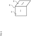
- Figure 6 illustrates a schematic view of a part surface 600 with surface elements 601, 602 and corresponding desired coating thickness ranges in accordance with another disclosed embodiment.
- surface 600 has desired coating thickness ranges of 8 mm on the left surface element 601 and 10-12 mm on the right surface element 602. Assume that the allowed delta for the whole surface 600 is selected to be 1.5 mm for this example embodiment.
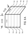
- Figure 7 illustrates a schematic view of the part surface of Figure 6 where ten surface elements 701-710 have been considered for generating a coating robotic program according to disclosed embodiments.
- the robot moves along robotic locations 720, 730 and 740 to spray a first surface segment consisting of the two upper surface elements 701, 702.
- the surface 600 consists of five segments, whereby a segment consists of two adjacent surface elements 701-702, 703-704, ..., 709-710 which are coated in one robotic path consisting of three consequent robotic locations 720, 730 and 740.
- algorithm steps include:
- Figures 8A-C illustrate schematic views showing valid and non-valid thickness coverages on surfaces according to disclosed embodiments.
- the simulated coating thickness results are in a valid range while in Figures 8 B and 8 C the simulated coating thickness results are not in a valid range.
- the thickness value of 10 mm for surface element 701 is outside the desired coverage of 8 mm with a delta of 1.5 mm and for Figure 8 C the thickness value of 11 mm has a delta above 1.5 mm with respect of the 8 mm of the adjacent surface element.
- a robotic program for industrial coating is generated, for an industrial process where coating material is to be applied on a surface of an industrial object by a coating gun of a robot.
- the algorithm steps include:
- At least one of the tuned iterations include selecting a different coating gun, brush and/or coating angle between the object surface and the coating gun. Accordingly, a different corresponding coating dispersion object is then used during the simulation.
- the output of the coating prediction module depends on the coating dispersion object used for the input training data during the training of the ML module.
- several dispersion objects can be used. According to embodiments, it is possible to use a single ML module by inserting the dispersion object index as part of the tuple x so that the index is part of the input data tuple x. According to other embodiments, several ML modules are used one for each coating dispersion object and for prediction purposes the relevant ML module is used each time.
- the data describing the robotic locations comprise at least information on the positions of the location (e.g. poses, positions and/or directions of the location) and, optionally, it may additionally comprise information on the robotic motion at the location (e.g. speed, acceleration, tension, state and/or other robotic motion related information at the location).
- the output data tuple y comprises the minimum information required for describing the robotic program of the specific robot.
- the information describing the location position may be given in the form of spatial coordinates describing the robot's tip position independently on the robot type or it may be given as robot poses (e.g. via robot's joint values). In other embodiments, the location position information may be given in other formats that may or may not be robot specific.
- position information of the robotic locations may conveniently be given as relative to a given reference frame of the specific robot.
- the given reference frame of the specific robot may be the robot base frame.
- the input data comprises robotic tool-related information.
- robot tool-related information may comprise robot's tool type and/or tool differential position information.
- the differential tool position information may preferably be the delta between the robot's tool frame and the robot's TCPF frame.
- the object surface to be coated is the surface of a support material for additive manufacturing purposes.
- Figure 9 illustrates a flowchart 900 of a method for generating a robotic program for industrial coating in accordance with disclosed embodiments. Such method can be performed, for example, by system 100 of Figure 1 described above, but the "system" in the process below can be any apparatus configured to perform a process as described.
- inputs are received including virtual representation of a robot, virtual representation of a robotic coating gun, virtual representation of a set of elements of the object surface to be coated and a set of desired coating thickness ranges, virtual representation of an industrial sub-cell.
- At act 904 inputs on a coating dispersion object to be mounted on the coating gun for emulating coating behavior of the coating gun are received.
- the training data are processed for machine learning purposes to obtain first data tuples x and second data tuples y; wherein the x tuples are describing a point sequence on the surface, the corresponding coating thickness coverage and specific information on the robot and on the surface; wherein the y tuples are describing the corresponding robotic program.
- At least one of the tuned iterations include selecting a different coating gun, brush and/or angle and by selecting a different corresponding coating dispersion object.
- a coating dispersion object generated via a machine learning algorithm In embodiments, inputs on a coating dispersion object generated via a machine learning algorithm are received.
- machine usable/readable or computer usable/readable mediums include: nonvolatile, hard-coded type mediums such as read only memories (ROMs) or erasable, electrically programmable read only memories (EEPROMs), and user-recordable type mediums such as floppy disks, hard disk drives and compact disk read only memories (CD-ROMs) or digital versatile disks (DVDs).
- ROMs read only memories
- EEPROMs electrically programmable read only memories
- user-recordable type mediums such as floppy disks, hard disk drives and compact disk read only memories (CD-ROMs) or digital versatile disks (DVDs).
Landscapes
- Engineering & Computer Science (AREA)
- Mechanical Engineering (AREA)
- Robotics (AREA)
- Theoretical Computer Science (AREA)
- Physics & Mathematics (AREA)
- Evolutionary Computation (AREA)
- Software Systems (AREA)
- Artificial Intelligence (AREA)
- General Engineering & Computer Science (AREA)
- General Physics & Mathematics (AREA)
- Medical Informatics (AREA)
- Computer Vision & Pattern Recognition (AREA)
- Geometry (AREA)
- Computer Hardware Design (AREA)
- Data Mining & Analysis (AREA)
- Computing Systems (AREA)
- Mathematical Physics (AREA)
- Manipulator (AREA)
- Spray Control Apparatus (AREA)
- Application Of Or Painting With Fluid Materials (AREA)
Claims (9)
- Verfahren zur Erzeugung eines Roboterprogramms für industrielle Beschichtung durch ein Datenverarbeitungssystem, wobei Beschichtungsmaterial durch eine Beschichtungspistole eines Roboters auf eine Fläche eines industriellen Objekts aufzubringen ist, wobei das Verfahren die folgenden Schritte umfasst:a) Empfangen (902) von Eingaben, die eine virtuelle Darstellung eines Roboters (202), eine virtuelle Darstellung einer Roboter-Beschichtungspistole (203), eine virtuelle Darstellung eines Satzes von Elementen der zu beschichtenden Objektfläche (204) und eines Satzes von gewünschten Beschichtungsdickenbereichen, eine virtuelle Darstellung einer industriellen Teilzelle (201) beinhalten;b) Empfangen (904) von Eingaben auf einem auf der Beschichtungspistole (207) zu montierenden Beschichtungsdispersionsobjekt (207) zum Nachbilden eines Beschichtungsverhaltens der Beschichtungspistole;c) synthetisches Erzeugen von Trainingsdaten einer Vielzahl von Roboterprogrammen für die industrielle Beschichtung und deren entsprechende Beschichtungsdickenabdeckung auf einer Vielzahl von Flächen für eine Vielzahl von Szenarien;d) Verarbeiten (908) der Trainingsdaten für Zwecke des Maschinenlernens, um erste Datentupel x und zweite Datentupel y zu erhalten; wobei die x-Tupel eine Punktfolge auf der Fläche, die entsprechende Beschichtungsdickenabdeckung und wechselseitige Informationen des Roboterteils beschreiben; wobei die y-Tupel das entsprechende Roboterprogramm als eine Liste von Roboterstandorten beschreiben;e) Erlernen (910) unter Verwendung von überwachten Lernalgorithmen einer Funktion, welche die x-Tupel in die y-Tupel abbildet, aus den verarbeiteten Daten, um ein Beschichtungsvorhersagemodul für den Roboter zu erzeugen;f) Vorgehen (912), beginnend mit einer vorgegebenen, ausgewählten, gültigen Dickenabdeckung als Eingabeparameter, wobei die ausgewählte, gültige Dickenabdeckung für jeden Punkt ein gültiger Beschichtungsdickenwert ist, d. h. gültig unter Bereichs- und Delta-Einschränkungen, wobei der Delta-Wert vorgegeben ist, um anzugeben, was der akzeptable maximale Wertunterschied zwischen Punkten desselben Flächenelements oder über verschiedene Flächenelemente hinweg ist, für eine vorgegebene Punktfolge jedes vorgegebenen Flächenelements auf eine iterative Weise mit Folgendem:- Vorhersagen eines Roboterprogramms über das Beschichtungsvorhersagemodul;- Simulieren des vorhergesagten Roboterprogramms mit einer Kollisionserkennungsmaschine innerhalb der industriellen Teilzelle;- Berechnen der Dickenwerte des Beschichtungsmaterials auf dem vorgegebenen Flächenelement durch erfasste Kollisionen zwischen Elementen des auf der verwendeten Roboter-Beschichtungspistole montierten Beschichtungsdispersionsobjekts und Teilelementen des vorgegebenen Flächenelements;wobei die Eingabeparameter iterativ abgestimmt werden, bis die berechneten Dickenwerte dem Satz gewünschter Beschichtungsdickenbereiche entsprechen und keine unzulässigen Roboterkollisionen innerhalb der industriellen Teilzelle auftreten; undg) Erzeugen (914) eines Beschichtungsroboterprogramms für jedes Flächenelement basierend auf einem oder mehreren vorhergesagten, aus Schritt f) resultierenden Roboterprogrammen.
- Verfahren nach Anspruch 1, wobei mindestens eine der abgestimmten Iterationen Auswählen einer anderen Beschichtungspistole, -bürste und/oder eines anderen Beschichtungswinkels und durch Auswählen eines anderen entsprechenden Beschichtungsdispersionsobjekts beinhaltet.
- Verfahren nach Anspruch 1 oder 2, wobei das Verfahren Empfangen von Eingaben auf einem Beschichtungsdispersionsobjekt umfasst, das über einen Algorithmus für Maschinenlernen erzeugt wird.
- Datenverarbeitungssystem, umfassend:einen Prozessor; undeinen zugänglichen Speicher, wobei das Datenverarbeitungssystem zu Folgendem konfiguriert ist:a) Empfangen (902) von Eingaben, die eine virtuelle Darstellung eines Roboters (202), eine virtuelle Darstellung einer Roboter-Beschichtungspistole (203), eine virtuelle Darstellung eines Satzes von Elementen der zu beschichtenden Objektfläche (204) und eines Satzes von gewünschten Beschichtungsdickenbereichen, eine virtuelle Darstellung einer industriellen Teilzelle (201) beinhalten;b) Empfangen (904) von Eingaben auf einem auf der Beschichtungspistole (207) zu montierenden Beschichtungsdispersionsobjekt (207) zum Nachbilden eines Beschichtungsverhaltens der Beschichtungspistole;c) synthetisches Erzeugen von Trainingsdaten einer Vielzahl von Roboterprogrammen für die industrielle Beschichtung und deren entsprechende Beschichtungsdickenabdeckung auf einer Vielzahl von Flächen für eine Vielzahl von Szenarien;d) Verarbeiten (908) der Trainingsdaten für Zwecke des Maschinenlernens, um erste Datentupel x und zweite Datentupel y zu erhalten; wobei die x-Tupel eine Punktfolge auf der Fläche, die entsprechende Beschichtungsdickenabdeckung und wechselseitige Informationen des Roboterteils beschreiben;
wobei die y-Tupel das entsprechende Roboterprogramm als eine Liste von Roboterstandorten beschreiben;e) Erlernen (910) unter Verwendung von überwachten Lernalgorithmen einer Funktion, welche die x-Tupel in die y-Tupel abbildet, aus den verarbeiteten Daten, um ein Beschichtungsvorhersagemodul für den Roboter zu erzeugen;f) Vorgehen (912), beginnend mit einer vorgegebenen, ausgewählten, gültigen Dickenabdeckung als Eingabeparameter, wobei die ausgewählte, gültige Dickenabdeckung für jeden Punkt ein gültiger Beschichtungsdickenwert ist, d. h. gültig unter Bereichs- und Delta-Einschränkungen, wobei der Delta-Wert vorgegeben ist, um anzugeben, was der akzeptable maximale Wertunterschied zwischen Punkten desselben Flächenelements oder über verschiedene Flächenelemente hinweg ist, für eine vorgegebene Punktfolge jedes vorgegebenen Flächenelements auf eine iterative Weise mit Folgendem:- Vorhersagen eines Roboterprogramms über das Beschichtungsvorhersagemodul;- Simulieren des vorhergesagten Roboterprogramms mit einer Kollisionserkennungsmaschine innerhalb der industriellen Teilzelle;- Berechnen der Dickenwerte des Beschichtungsmaterials auf dem vorgegebenen Flächenelement durch erfasste Kollisionen zwischen Elementen des auf der verwendeten Roboter-Beschichtungspistole montierten Beschichtungsdispersionsobjekts und Teilelementen des vorgegebenen Flächenelements;wobei die Eingabeparameter iterativ abgestimmt werden, bis die berechneten Dickenwerte dem Satz gewünschter Beschichtungsdickenbereiche entsprechen und keine unzulässigen Roboterkollisionen innerhalb der industriellen Teilzelle auftreten; undg) Erzeugen (914) eines Beschichtungsroboterprogramms für jedes Flächenelement basierend auf einem oder mehreren resultierenden vorhergesagten Roboterprogrammen. - Datenverarbeitungssystem nach Anspruch 4, wobei das Datenverarbeitungssystem zum Auswählen einer anderen Beschichtungspistole, -bürste und/oder eines anderen Beschichtungswinkels während mindestens einer Iteration und zum Auswählen eines anderen entsprechenden Beschichtungsdispersionsobjekts konfiguriert ist.
- Datenverarbeitungssystem nach Anspruch 4 oder 5, wobei das Datenverarbeitungssystem zum Empfangen von Eingaben auf einem Beschichtungsdispersionsobjekt konfiguriert ist, das über einen Algorithmus für Maschinenlernen erzeugt wird.
- Nichtflüchtiges computerlesbares Medium, das mit ausführbaren Anweisungen codiert ist, die beim Ausführen ein oder mehrere Datenverarbeitungssysteme zu Folgendem veranlassen:a) Empfangen (902) von Eingaben, die eine virtuelle Darstellung eines Roboters (202), eine virtuelle Darstellung einer Roboter-Beschichtungspistole (203), eine virtuelle Darstellung eines Satzes von Elementen der zu beschichtenden Objektfläche (204) und eines Satzes von gewünschten Beschichtungsdickenbereichen, eine virtuelle Darstellung einer industriellen Teilzelle (201) beinhalten;b) Empfangen (904) von Eingaben auf einem auf der Beschichtungspistole (207) zu montierenden Beschichtungsdispersionsobjekt (207) zum Nachbilden eines Beschichtungsverhaltens der Beschichtungspistole;c) synthetisches Erzeugen von Trainingsdaten einer Vielzahl von Roboterprogrammen für die industrielle Beschichtung und deren entsprechende Beschichtungsdickenabdeckung auf einer Vielzahl von Flächen für eine Vielzahl von Szenarien;d) Verarbeiten (908) der Trainingsdaten für Zwecke des Maschinenlernens, um erste Datentupel x und zweite Datentupel y zu erhalten; wobei die x-Tupel eine Punktfolge auf der Fläche, die entsprechende Beschichtungsdickenabdeckung und wechselseitige Informationen des Roboterteils beschreiben; wobei die y-Tupel das entsprechende Roboterprogramm als eine Liste von Roboterstandorten beschreiben;e) Erlernen (910) durch überwachte Lernalgorithmen einer Funktion, welche die x-Tupel in die y-Tupel abbildet, aus den verarbeiteten Daten, um ein Beschichtungsvorhersagemodul für den Roboter zu erzeugen;f) Vorgehen (912), beginnend mit einer vorgegebenen, ausgewählten, gültigen Dickenabdeckung als Eingabeparameter, wobei die ausgewählte, gültige Dickenabdeckung für jeden Punkt ein gültiger Beschichtungsdickenwert ist, d. h. gültig unter Bereichs- und Delta-Einschränkungen, wobei der Delta-Wert vorgegeben ist, um anzugeben, was der akzeptable maximale Wertunterschied zwischen Punkten desselben Flächenelements oder über verschiedene Flächenelemente hinweg ist, für eine vorgegebene Punktfolge jedes vorgegebenen Flächenelements auf eine iterative Weise mit Folgendem:- Vorhersagen eines Roboterprogramms über das Beschichtungsvorhersagemodul;- Simulieren des vorhergesagten Roboterprogramms mit einer Kollisionserkennungsmaschine innerhalb der industriellen Teilzelle;- Berechnen der Dickenwerte des Beschichtungsmaterials auf dem vorgegebenen Flächenelement durch erfasste Kollisionen zwischen Elementen des auf der verwendeten Roboter-Beschichtungspistole montierten Beschichtungsdispersionsobjekts und Teilelementen des vorgegebenen Flächenelements;wobei die Eingabeparameter iterativ abgestimmt werden, bis die berechneten Dickenwerte dem Satz gewünschter Beschichtungsdickenbereiche entsprechen und keine unzulässigen Roboterkollisionen innerhalb der industriellen Teilzelle auftreten; undg) Erzeugen (914) eines Beschichtungsroboterprogramms für jedes Flächenelement basierend auf einem oder mehreren resultierenden vorhergesagten Roboterprogrammen.
- Nichtflüchtiges computerlesbares Medium nach Anspruch 7, wobei während mindestens einer Iteration eine andere Beschichtungspistole, -bürste und/oder ein anderer Beschichtungswinkel ausgewählt wird und ein anderes entsprechendes Beschichtungsdispersionsobjekt ausgewählt wird.
- Nichtflüchtiges computerlesbares Medium nach Anspruch 7 oder 8, wobei empfangene Eingaben auf einem Beschichtungsdispersionsobjekt über einen Algorithmus für Maschinenlernen erzeugt werden.
Priority Applications (3)
| Application Number | Priority Date | Filing Date | Title |
|---|---|---|---|
| EP19180630.6A EP3753683B1 (de) | 2019-06-17 | 2019-06-17 | Verfahren und system zur erzeugung eines roboterprogramms für industrielle beschichtung |
| CN202010548542.8A CN112091964B (zh) | 2019-06-17 | 2020-06-16 | 生成用于工业涂布的机器人程序的方法和系统 |
| US16/903,610 US11648579B2 (en) | 2019-06-17 | 2020-06-17 | Method and system for generating a robotic program for industrial coating |
Applications Claiming Priority (1)
| Application Number | Priority Date | Filing Date | Title |
|---|---|---|---|
| EP19180630.6A EP3753683B1 (de) | 2019-06-17 | 2019-06-17 | Verfahren und system zur erzeugung eines roboterprogramms für industrielle beschichtung |
Publications (3)
| Publication Number | Publication Date |
|---|---|
| EP3753683A1 EP3753683A1 (de) | 2020-12-23 |
| EP3753683B1 true EP3753683B1 (de) | 2025-01-01 |
| EP3753683C0 EP3753683C0 (de) | 2025-01-01 |
Family
ID=66912744
Family Applications (1)
| Application Number | Title | Priority Date | Filing Date |
|---|---|---|---|
| EP19180630.6A Active EP3753683B1 (de) | 2019-06-17 | 2019-06-17 | Verfahren und system zur erzeugung eines roboterprogramms für industrielle beschichtung |
Country Status (3)
| Country | Link |
|---|---|
| US (1) | US11648579B2 (de) |
| EP (1) | EP3753683B1 (de) |
| CN (1) | CN112091964B (de) |
Families Citing this family (8)
| Publication number | Priority date | Publication date | Assignee | Title |
|---|---|---|---|---|
| DE102021200190B4 (de) * | 2021-01-11 | 2025-05-22 | Geze Gmbh | Verfahren zum Bereitstellen eines Konfigurations-Datensatzes einer Entität |
| EP4063083B1 (de) * | 2021-03-26 | 2025-09-17 | Siemens Aktiengesellschaft | Verfahren zur konfigurierung einer beschichtungsmaschine |
| CN115178397B (zh) * | 2022-07-07 | 2024-08-16 | 阿维塔科技(重庆)有限公司 | 喷涂程序调试方法、装置、设备及计算机可读存储介质 |
| DE102022213893A1 (de) * | 2022-12-19 | 2024-06-20 | Siemens Aktiengesellschaft | System und Verfahren zur Bereitstellung eines Lackierprogramms für die Beschichtung von Leiterplatten |
| US12276989B1 (en) * | 2023-10-30 | 2025-04-15 | Claryo, Inc. | Systems and methods for a virtual facility supporting robotics fleet control and sensor data simulation |
| CN117970818B (zh) * | 2024-04-01 | 2024-05-31 | 深圳桥通物联科技有限公司 | 一种基于物联网的工业设备调控方法 |
| CN118818016B (zh) * | 2024-09-13 | 2025-01-17 | 潍柴动力股份有限公司 | 发动机喷漆质量的检测方法、装置、存储介质与电子设备 |
| CN119057804B (zh) * | 2024-09-30 | 2025-12-02 | 上海蔚建科技有限公司 | 喷涂机器人姿态补偿预测系统及喷涂机器人 |
Family Cites Families (16)
| Publication number | Priority date | Publication date | Assignee | Title |
|---|---|---|---|---|
| JP2004243215A (ja) * | 2003-02-13 | 2004-09-02 | Suzuki Motor Corp | シーラー塗布装置のロボットティーチング方法及びシーラー塗布装置 |
| US7722916B2 (en) * | 2006-05-30 | 2010-05-25 | General Electric Company | Methods for controlling plasma spray coating porosity on an article and articles manufactured therefrom |
| WO2011053368A1 (en) * | 2009-10-27 | 2011-05-05 | Siemens Aktiengesellschaft | Method for simulating of the thickness of a coating |
| CN101791801B (zh) * | 2010-01-15 | 2012-06-06 | 广东工业大学 | 工业机器人运动规划与性能测试系统及其实现方法 |
| CN101920233A (zh) * | 2010-07-09 | 2010-12-22 | 广东工业大学 | 一种基于虚拟现实技术的喷涂工业机器人综合控制系统及控制方法 |
| US20120156362A1 (en) * | 2010-12-21 | 2012-06-21 | Alexandr Sadovoy | Method and device for coating path generation |
| EP2882574A1 (de) * | 2012-08-08 | 2015-06-17 | ABB Technology AG | System und verfahren zur bestimmung eines optimalen pfades für materialausgaberoboter |
| CN103464344B (zh) * | 2013-09-23 | 2016-01-20 | 电子科技大学中山学院 | 一种经济型喷涂机器人喷枪轨迹规划方法 |
| EP2899497B1 (de) * | 2014-01-28 | 2019-03-13 | ABB Schweiz AG | Sensorsystem und Verfahren zur Charakterisierung einer nassen Farbschicht |
| CN104324861B (zh) * | 2014-08-12 | 2016-06-15 | 清华大学 | 一种多参数时变机器人喷涂方法 |
| US10339233B2 (en) * | 2015-07-27 | 2019-07-02 | Siemens Industry Software Ltd. | Calculating thicknesses of applied coating material |
| US9839936B2 (en) * | 2015-08-04 | 2017-12-12 | Northrop Grumman Systems Corporation | Smart technologies automated coatings |
| US9811074B1 (en) * | 2016-06-21 | 2017-11-07 | TruPhysics GmbH | Optimization of robot control programs in physics-based simulated environment |
| CN106354932B (zh) * | 2016-08-30 | 2019-12-17 | 江苏大学 | 平滑曲面间弧面型曲面过渡区域的机器人喷涂及轨迹设定方法 |
| US10537910B2 (en) * | 2016-09-08 | 2020-01-21 | The Boeing Company | Master application paths for coatings |
| US10969215B2 (en) * | 2017-08-04 | 2021-04-06 | Rolls-Royce North American Technologies, Inc. | Adaptive control of coating thickness |
-
2019
- 2019-06-17 EP EP19180630.6A patent/EP3753683B1/de active Active
-
2020
- 2020-06-16 CN CN202010548542.8A patent/CN112091964B/zh active Active
- 2020-06-17 US US16/903,610 patent/US11648579B2/en active Active
Also Published As
| Publication number | Publication date |
|---|---|
| CN112091964B (zh) | 2024-04-30 |
| US20200391241A1 (en) | 2020-12-17 |
| EP3753683A1 (de) | 2020-12-23 |
| US11648579B2 (en) | 2023-05-16 |
| CN112091964A (zh) | 2020-12-18 |
| EP3753683C0 (de) | 2025-01-01 |
Similar Documents
| Publication | Publication Date | Title |
|---|---|---|
| EP3753683B1 (de) | Verfahren und system zur erzeugung eines roboterprogramms für industrielle beschichtung | |
| US10414047B2 (en) | Method and a data processing system for simulating and handling of anti-collision management for an area of a production plant | |
| US10339233B2 (en) | Calculating thicknesses of applied coating material | |
| US9469029B2 (en) | Method and apparatus for saving energy and reducing cycle time by optimal ordering of the industrial robotic path | |
| US9135392B2 (en) | Semi-autonomous digital human posturing | |
| EP3166084B1 (de) | Verfahren und system zur bestimmung der konfiguration eines virtuellen roboters in einer virtuellen umgebung | |
| US20220019939A1 (en) | Method and system for predicting motion-outcome data of a robot moving between a given pair of robotic locations | |
| US20160031083A1 (en) | Method and apparatus for industrial robotic energy saving optimization using fly-by | |
| EP2998078A1 (de) | Verfahren zur verbesserung der effizienz des energieverbrauchs und der zykluszeit von industrierobotern durch die handhabung der ausrichtung bei dem bearbeitungsort | |
| WO2018122567A1 (en) | Method and system for determining a sequence of kinematic chains of a multiple robot | |
| Lin et al. | A new algorithm for determining a collision-free path for a CMM probe | |
| US20240253228A1 (en) | Method of generating program for robotic process | |
| EP4200677B1 (de) | Verfahren und datenverarbeitungssystem zur mehrzustandssimulation zur validierung der sicherheit eines industrieszenarios | |
| CN120122591A (zh) | 一种船舶装配仿真路径规划方法、系统、介质及终端 | |
| CN107066654A (zh) | 面向点云模型的包容盒面的轨迹控制点拾取方法和装置 | |
| CN117629203A (zh) | 复合机器人作业中底盘停靠点的生成方法、装置以及设备 | |
| WO2018051151A1 (en) | A method and a system for simulating and certifying safety management for an area of a production plant | |
| Ernst et al. | A method of CAD based automation and simulation by the example of virtual stone chipping testing | |
| Wardhana et al. | Enhanced waypoint graph for path planning in virtual worlds | |
| WO2024165895A1 (en) | Method and system for determining a position of a plurality of lidar sensors for industrial risky zones | |
| EP4662512A1 (de) | Verfahren und system zur bestimmung einer position einer vielzahl von lidar-sensoren für industrielle risikozonen | |
| CN120669709A (zh) | 多机器人协同加工的路径规划方法、装置、设备及介质 | |
| CN116136940A (zh) | 内部生成接触实体以在涉及非圆形梁单元的模拟中对接触行为建模 | |
| CN121132636A (zh) | 基于数字孪生的机器人作业空间干涉探测方法 | |
| KR20240108674A (ko) | 소독로봇의 이동경로 생성 방법 |
Legal Events
| Date | Code | Title | Description |
|---|---|---|---|
| PUAI | Public reference made under article 153(3) epc to a published international application that has entered the european phase |
Free format text: ORIGINAL CODE: 0009012 |
|
| STAA | Information on the status of an ep patent application or granted ep patent |
Free format text: STATUS: THE APPLICATION HAS BEEN PUBLISHED |
|
| AK | Designated contracting states |
Kind code of ref document: A1 Designated state(s): AL AT BE BG CH CY CZ DE DK EE ES FI FR GB GR HR HU IE IS IT LI LT LU LV MC MK MT NL NO PL PT RO RS SE SI SK SM TR |
|
| AX | Request for extension of the european patent |
Extension state: BA ME |
|
| STAA | Information on the status of an ep patent application or granted ep patent |
Free format text: STATUS: REQUEST FOR EXAMINATION WAS MADE |
|
| 17P | Request for examination filed |
Effective date: 20210623 |
|
| RBV | Designated contracting states (corrected) |
Designated state(s): AL AT BE BG CH CY CZ DE DK EE ES FI FR GB GR HR HU IE IS IT LI LT LU LV MC MK MT NL NO PL PT RO RS SE SI SK SM TR |
|
| STAA | Information on the status of an ep patent application or granted ep patent |
Free format text: STATUS: EXAMINATION IS IN PROGRESS |
|
| 17Q | First examination report despatched |
Effective date: 20220830 |
|
| GRAP | Despatch of communication of intention to grant a patent |
Free format text: ORIGINAL CODE: EPIDOSNIGR1 |
|
| STAA | Information on the status of an ep patent application or granted ep patent |
Free format text: STATUS: GRANT OF PATENT IS INTENDED |
|
| INTG | Intention to grant announced |
Effective date: 20240924 |
|
| GRAS | Grant fee paid |
Free format text: ORIGINAL CODE: EPIDOSNIGR3 |
|
| GRAA | (expected) grant |
Free format text: ORIGINAL CODE: 0009210 |
|
| STAA | Information on the status of an ep patent application or granted ep patent |
Free format text: STATUS: THE PATENT HAS BEEN GRANTED |
|
| AK | Designated contracting states |
Kind code of ref document: B1 Designated state(s): AL AT BE BG CH CY CZ DE DK EE ES FI FR GB GR HR HU IE IS IT LI LT LU LV MC MK MT NL NO PL PT RO RS SE SI SK SM TR |
|
| REG | Reference to a national code |
Ref country code: GB Ref legal event code: FG4D |
|
| REG | Reference to a national code |
Ref country code: CH Ref legal event code: EP |
|
| REG | Reference to a national code |
Ref country code: DE Ref legal event code: R096 Ref document number: 602019064159 Country of ref document: DE |
|
| REG | Reference to a national code |
Ref country code: IE Ref legal event code: FG4D |
|
| U01 | Request for unitary effect filed |
Effective date: 20250124 |
|
| U07 | Unitary effect registered |
Designated state(s): AT BE BG DE DK EE FI FR IT LT LU LV MT NL PT RO SE SI Effective date: 20250130 |
|
| PG25 | Lapsed in a contracting state [announced via postgrant information from national office to epo] |
Ref country code: PL Free format text: LAPSE BECAUSE OF FAILURE TO SUBMIT A TRANSLATION OF THE DESCRIPTION OR TO PAY THE FEE WITHIN THE PRESCRIBED TIME-LIMIT Effective date: 20250101 |
|
| PG25 | Lapsed in a contracting state [announced via postgrant information from national office to epo] |
Ref country code: ES Free format text: LAPSE BECAUSE OF FAILURE TO SUBMIT A TRANSLATION OF THE DESCRIPTION OR TO PAY THE FEE WITHIN THE PRESCRIBED TIME-LIMIT Effective date: 20250101 |
|
| PG25 | Lapsed in a contracting state [announced via postgrant information from national office to epo] |
Ref country code: IS Free format text: LAPSE BECAUSE OF FAILURE TO SUBMIT A TRANSLATION OF THE DESCRIPTION OR TO PAY THE FEE WITHIN THE PRESCRIBED TIME-LIMIT Effective date: 20250501 Ref country code: NO Free format text: LAPSE BECAUSE OF FAILURE TO SUBMIT A TRANSLATION OF THE DESCRIPTION OR TO PAY THE FEE WITHIN THE PRESCRIBED TIME-LIMIT Effective date: 20250401 |
|
| PG25 | Lapsed in a contracting state [announced via postgrant information from national office to epo] |
Ref country code: HR Free format text: LAPSE BECAUSE OF FAILURE TO SUBMIT A TRANSLATION OF THE DESCRIPTION OR TO PAY THE FEE WITHIN THE PRESCRIBED TIME-LIMIT Effective date: 20250101 |
|
| PG25 | Lapsed in a contracting state [announced via postgrant information from national office to epo] |
Ref country code: GR Free format text: LAPSE BECAUSE OF FAILURE TO SUBMIT A TRANSLATION OF THE DESCRIPTION OR TO PAY THE FEE WITHIN THE PRESCRIBED TIME-LIMIT Effective date: 20250402 |
|
| PG25 | Lapsed in a contracting state [announced via postgrant information from national office to epo] |
Ref country code: CZ Free format text: LAPSE BECAUSE OF FAILURE TO SUBMIT A TRANSLATION OF THE DESCRIPTION OR TO PAY THE FEE WITHIN THE PRESCRIBED TIME-LIMIT Effective date: 20250101 |
|
| U20 | Renewal fee for the european patent with unitary effect paid |
Year of fee payment: 7 Effective date: 20250620 |
|
| PG25 | Lapsed in a contracting state [announced via postgrant information from national office to epo] |
Ref country code: SM Free format text: LAPSE BECAUSE OF FAILURE TO SUBMIT A TRANSLATION OF THE DESCRIPTION OR TO PAY THE FEE WITHIN THE PRESCRIBED TIME-LIMIT Effective date: 20250101 |
|
| PGFP | Annual fee paid to national office [announced via postgrant information from national office to epo] |
Ref country code: GB Payment date: 20250710 Year of fee payment: 7 |
|
| PG25 | Lapsed in a contracting state [announced via postgrant information from national office to epo] |
Ref country code: SK Free format text: LAPSE BECAUSE OF FAILURE TO SUBMIT A TRANSLATION OF THE DESCRIPTION OR TO PAY THE FEE WITHIN THE PRESCRIBED TIME-LIMIT Effective date: 20250101 |
|
| PLBE | No opposition filed within time limit |
Free format text: ORIGINAL CODE: 0009261 |
|
| STAA | Information on the status of an ep patent application or granted ep patent |
Free format text: STATUS: NO OPPOSITION FILED WITHIN TIME LIMIT |