EP3753655A1 - Atomization device - Google Patents
Atomization device Download PDFInfo
- Publication number
- EP3753655A1 EP3753655A1 EP19382517.1A EP19382517A EP3753655A1 EP 3753655 A1 EP3753655 A1 EP 3753655A1 EP 19382517 A EP19382517 A EP 19382517A EP 3753655 A1 EP3753655 A1 EP 3753655A1
- Authority
- EP
- European Patent Office
- Prior art keywords
- spinning disc
- atomization device
- disc
- rotating shaft
- spinning
- Prior art date
- Legal status (The legal status is an assumption and is not a legal conclusion. Google has not performed a legal analysis and makes no representation as to the accuracy of the status listed.)
- Withdrawn
Links
Images
Classifications
-
- B—PERFORMING OPERATIONS; TRANSPORTING
- B22—CASTING; POWDER METALLURGY
- B22F—WORKING METALLIC POWDER; MANUFACTURE OF ARTICLES FROM METALLIC POWDER; MAKING METALLIC POWDER; APPARATUS OR DEVICES SPECIALLY ADAPTED FOR METALLIC POWDER
- B22F9/00—Making metallic powder or suspensions thereof
- B22F9/02—Making metallic powder or suspensions thereof using physical processes
- B22F9/06—Making metallic powder or suspensions thereof using physical processes starting from liquid material
- B22F9/08—Making metallic powder or suspensions thereof using physical processes starting from liquid material by casting, e.g. through sieves or in water, by atomising or spraying
- B22F9/10—Making metallic powder or suspensions thereof using physical processes starting from liquid material by casting, e.g. through sieves or in water, by atomising or spraying using centrifugal force
Definitions
- the present invention relates to a metal powder atomization device, particularly to a centrifugal atomization device in which molten metal is dispersed in the form of particles due to centrifugal force upon contact with a spinning disc.
- Atomization is a process of breaking up a bulk liquid into small droplets. Any material existing in liquid state can be atomized into micrometer-sized particles. This technique is used to produce elemental metal powder or alloys.
- Metal powder has a number of industrial applications, among which conventional powder metallurgy for the manufacture of parts by compaction and powder sintering, the formation of coatings by means of spray techniques, or the manufacture of components by means of additive manufacturing techniques stand out.
- Centrifugal atomization using a spinning disc is based on dropping a column of liquid against a disc, which can be flat or cup-shaped, among other shapes.
- a spinning disc which can be flat or cup-shaped, among other shapes.
- the liquid spreads out over the surface of the disc due to the centrifugal force to which it is subjected.
- the metal reaches the edge of the disc, the surface tension is insufficient to maintain the bulk liquid mass and accordingly turns into a spray of small droplets which solidify and form a powder.
- the liquid will be broken up into ligaments or sheets, or directly into droplets. Regardless of how the liquid is broken up, if the process is suitable, most of the particles end up being spherical.
- the spinning disc atomization (SDA) device comprises three basic groups:
- a cooling system is needed for the atomizing disc, so that it can work at temperatures such that it maintains the suitable mechanical strength and toughness properties.
- an objective of the present invention is to provide an atomization device in which the rotating shaft of the motor is perfectly aligned with the spinning disc, thereby avoiding the use of mechanical transmission elements, such as gears, belts, or other elements such as elastic couplings for connecting shafts, which complicate the design and increase the number of rotating elements.
- the simplicity of the design minimizes vibrations in the atomizing disc.
- the atomization device of the invention solves the mentioned drawbacks and presents other advantages that will be described below.
- the atomization device comprises a motor rotatably driving a spinning disc by means of a rotating shaft, and cooling means for cooling said spinning disc, wherein said cooling means comprise a cooling circuit extending around at least one portion of the rotating shaft and below at least one portion of said spinning disc.
- the cooling circuit is not located in the actual rotating shaft, it is possible for the drive system of the disc to be simpler, enabling perfect alignment of the rotating shaft of the motor with the spinning disc. This minimizes rotating moving parts, which prevents vibrations from being produced.
- said cooling circuit is located in a stationary base in turn acting as a collector for the cooling circuit, comprising at least one inlet and one outlet for liquid coolant.
- These inlets and outlets for liquid coolant into the lower area of the disc are located around, on the sides, and parallel to the shaft of the atomizing disc. They are characterized by being able to be distributed in various positions and with various shapes and section around the area of the shaft of the disc.
- the atomization device according to the present invention also advantageously comprises at least one gasket with its corresponding closure system should one be required, arranged between the spinning disc and the stationary base. Said gasket maintains tightness and confines the liquid coolant.
- This gasket can be made of graphite, for example.
- said at least one gasket is arranged in a stationary manner, i.e., it does not spin with the spinning disc, as are the closure elements keeping the gasket in contact with the disc, such that only the shaft and disc part is rotating.
- said spinning disc and said rotating shaft consist of a single part, which also minimizes unwanted misalignments and vibrations in the assembly.
- the spinning disc is made of metal, with or without a refractory, anti-corrosion and/or anti-wear coating on its outer surface, although it can also be made of a ceramic material that adapts to the required mechanical conditions.
- the spinning disc has a diameter comprised between 20 and 200 mm and a thickness comprised between 1 and 15 mm.
- the atomization device comprises a motor 1 rotatably driving a spinning disc 2 through a rotating shaft 3.
- Said spinning disc 2 and said rotating shaft 3 may or may not consist of a single part.
- atomization takes place by dropping a column or droplets of liquid against the spinning disc 2, which may be flat, cup-shaped, or have other shapes or geometries.
- this spinning disc 2 requires cooling which is provided, according to the present invention, by means of a cooling circuit, generally indicated by means of reference number 4, which is not arranged inside the rotating shaft 3, but rather extends around at least one portion of the rotating shaft 3 and below at least one portion of said spinning disc 2.
- this cooling circuit 4 comprises at least one inlet 5 for liquid coolant, for example, water or oil, and at least one outlet 6 for said liquid coolant.
- the atomization device comprises at least one, and preferably two, friction bearings 15 arranged between the rotating shaft 3 and the stationary base 7.
- the cooling circuit 4 comprises at least one vertical inlet segment 10 and at least one vertical outlet segment 11 for the liquid coolant which are parallel to and spaced apart from the rotating shaft of the disc, which allows cooling specifically the upper portion of the rotating shaft 3 and the lower portion of the spinning disc 2.
- the atomization device comprises a sealing gasket 13, with its corresponding closure system should it be required, arranged between the stationary base 7 and the spinning disc 2, where said gasket 13 may preferably be made of graphite, though it could be made of any suitable material.
- Said gasket 13 with its corresponding closure system should one be required, is stationary, arranged between the spinning disc 2 and the stationary base 7. Said gasket maintains tightness and confines the liquid coolant.
- a sealing gasket 12 is also arranged between the rotating shaft 3 and the stationary base 7 for the purpose of confining the liquid coolant in the lower portion of the disc 2.
- This gasket 12 will preferably be made of an elastomeric material, though it may be made of any type of material that assures tightness in said area, such as graphite for example.
- the spinning disc 2 can be made of any suitable material, but it is preferably made of metal or ceramic, with or without a refractory, anti-corrosion and/or anti-wear coating on its outer surface
- the spinning disc 2 may be made of AISI H13 steel, which is suitable for hot working.
- a suitable refractory coating could be made of alumina or zirconia to avoid interaction between the metal of the disc and the atomized metal.
- the diameter of the spinning disc 2 can range from 20 to 200 mm and the thickness can range from 1 to 15 mm.
- the table below includes several atomization embodiments obtained by means of the atomization device according to the present invention: Material atomized Speed of the spinning disc (rpm) Mean particle diameter ( ⁇ m) Temperature of the molten metal (°C) Tin 30,000 90 400°C 40,000 75 Aluminum 20,000 190 750°C 30,000 140 Copper 15,000 180 1100°C 20,000 150
Landscapes
- Manufacture Of Metal Powder And Suspensions Thereof (AREA)
- Glanulating (AREA)
- Nozzles (AREA)
Abstract
The atomization device comprises a motor (1) rotatably driving a spinning disc (2) by means of a rotating shaft (3), and cooling means for cooling said spinning disc (2), wherein said cooling means comprise a cooling circuit (4) extending around at least one portion of the rotating shaft (3) and below at least one portion of said spinning disc (2).
The invention allows providing an atomization device in which the rotating shaft of the motor is perfectly aligned with the spinning disc, thereby avoiding the use of mechanical transmission elements.
Description
- The present invention relates to a metal powder atomization device, particularly to a centrifugal atomization device in which molten metal is dispersed in the form of particles due to centrifugal force upon contact with a spinning disc.
- Atomization is a process of breaking up a bulk liquid into small droplets. Any material existing in liquid state can be atomized into micrometer-sized particles. This technique is used to produce elemental metal powder or alloys.
- Metal powder has a number of industrial applications, among which conventional powder metallurgy for the manufacture of parts by compaction and powder sintering, the formation of coatings by means of spray techniques, or the manufacture of components by means of additive manufacturing techniques stand out.
- There are different atomization processes distinguished from one another by the techniques used for breaking up the fluid being used. These can be classified as:
- Atomization with fluids: metal in liquid state is transformed into small droplets due to the interaction of different high-pressure jets of water, gas, or oil, whether with a jet of water, air, hydrocarbons, or oil.
- Centrifugal atomization: molten metal is dispersed in the form of particles due to centrifugal force, such as spinning disc or rotating electrode atomization techniques.
- Other techniques, such as soluble gas, ultrasonic, or vibrating electrode atomization.
- Centrifugal atomization using a spinning disc (Spinning Disc Atomization - SDA) is based on dropping a column of liquid against a disc, which can be flat or cup-shaped, among other shapes. When the liquid contacts the disc spinning at a high speed, the liquid spreads out over the surface of the disc due to the centrifugal force to which it is subjected. Then, when the metal reaches the edge of the disc, the surface tension is insufficient to maintain the bulk liquid mass and accordingly turns into a spray of small droplets which solidify and form a powder.
- According to the speed, the radius of the disc, or the flow rate of the molten metal falling onto said disc, the liquid will be broken up into ligaments or sheets, or directly into droplets. Regardless of how the liquid is broken up, if the process is suitable, most of the particles end up being spherical.
- By way of example, the spinning disc atomization (SDA) device comprises three basic groups:
- A crucible for melting the metal to be atomized, which must be adapted for pouring the metal onto the disc.
- A spinning disc, which is the element in charge of atomization of the liquid, and it must be capable of withstanding high speeds and temperatures.
- A chamber where atomization is performed which must be large enough to allow solidification of the particles before they hit against the walls of the chamber. It also preferably allows atomizing under conditions of inert atmosphere, and thus preventing possible oxidation of the particles as they solidify.
- To assure the structural integrity of the atomizing disc, particularly where materials with a high melting point are to be atomized, a cooling system is needed for the atomizing disc, so that it can work at temperatures such that it maintains the suitable mechanical strength and toughness properties.
- As an example, for AISI H13 steel, used in hot-working applications for cases where good mechanical properties at a high temperature must be assured, maximum temperatures recommended for working with these steels is about 450°C, since past this temperature their mechanical properties begin to deteriorate. This recommended working temperature is significantly lower than the melting temperatures of the metals, and for this reason the atomizing disc must be cooled.
- For proper cooling of the spinning disc, said cooling today is normally provided through the lower portion of the atomizing disc. To that end, these designs mean that the rotating shaft is hollow, which leads to a complex design of the drive system of this disc, which is prone to misalignments and vibrations, with the subsequent problems this entails.
- Therefore, an objective of the present invention is to provide an atomization device in which the rotating shaft of the motor is perfectly aligned with the spinning disc, thereby avoiding the use of mechanical transmission elements, such as gears, belts, or other elements such as elastic couplings for connecting shafts, which complicate the design and increase the number of rotating elements. The simplicity of the design minimizes vibrations in the atomizing disc.
- The atomization device of the invention solves the mentioned drawbacks and presents other advantages that will be described below.
- The atomization device according to the present invention comprises a motor rotatably driving a spinning disc by means of a rotating shaft, and cooling means for cooling said spinning disc, wherein said cooling means comprise a cooling circuit extending around at least one portion of the rotating shaft and below at least one portion of said spinning disc.
- Because the cooling circuit is not located in the actual rotating shaft, it is possible for the drive system of the disc to be simpler, enabling perfect alignment of the rotating shaft of the motor with the spinning disc. This minimizes rotating moving parts, which prevents vibrations from being produced.
- According to a preferred embodiment, said cooling circuit is located in a stationary base in turn acting as a collector for the cooling circuit, comprising at least one inlet and one outlet for liquid coolant. These inlets and outlets for liquid coolant into the lower area of the disc are located around, on the sides, and parallel to the shaft of the atomizing disc. They are characterized by being able to be distributed in various positions and with various shapes and section around the area of the shaft of the disc.
- Furthermore, the atomization device according to the present invention also advantageously comprises at least one gasket with its corresponding closure system should one be required, arranged between the spinning disc and the stationary base. Said gasket maintains tightness and confines the liquid coolant. This gasket can be made of graphite, for example. There is also arranged a sealing gasket between the shaft and the base.
- Advantageously, said at least one gasket is arranged in a stationary manner, i.e., it does not spin with the spinning disc, as are the closure elements keeping the gasket in contact with the disc, such that only the shaft and disc part is rotating.
- According to a preferred embodiment, said spinning disc and said rotating shaft consist of a single part, which also minimizes unwanted misalignments and vibrations in the assembly.
- Preferably, the spinning disc is made of metal, with or without a refractory, anti-corrosion and/or anti-wear coating on its outer surface, although it can also be made of a ceramic material that adapts to the required mechanical conditions.
- According to a preferred embodiment, the spinning disc has a diameter comprised between 20 and 200 mm and a thickness comprised between 1 and 15 mm.
- To better understand the foregoing, a set of drawings are attached in which a practical embodiment is schematically depicted merely by way of illustrative nonlimiting example.
-
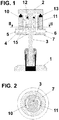
Figure 1 is elevational cross-section view of the atomization device according to the present invention; and -
Figure 2 is a plan view of the upper portion of the atomization device according to the present invention, with the spinning disc removed. - As shown in the drawings, the atomization device according to the present invention comprises a
motor 1 rotatably driving aspinning disc 2 through a rotatingshaft 3. Said spinningdisc 2 and said rotatingshaft 3 may or may not consist of a single part. - As indicated above, atomization takes place by dropping a column or droplets of liquid against the spinning
disc 2, which may be flat, cup-shaped, or have other shapes or geometries. - When the liquid contacts the
disc 2 spinning at a high speed, said liquid spreads out over the surface of thedisc 2 due to the centrifugal force to which it is subjected, and when the metal reaches the edge of thedisc 2, the surface tension is insufficient to maintain the bulk liquid mass and accordingly turns into a spray of small droplets which solidify and form a powder. - Also as described above, this spinning
disc 2 requires cooling which is provided, according to the present invention, by means of a cooling circuit, generally indicated by means ofreference number 4, which is not arranged inside the rotatingshaft 3, but rather extends around at least one portion of the rotatingshaft 3 and below at least one portion of said spinningdisc 2. - Furthermore, this
cooling circuit 4 comprises at least oneinlet 5 for liquid coolant, for example, water or oil, and at least oneoutlet 6 for said liquid coolant. - Said
base 7 is stationary, i.e., it does not spin with the rotatingshaft 3 and with the spinningdisc 2. To that end, the atomization device according to the present invention comprises at least one, and preferably two,friction bearings 15 arranged between the rotatingshaft 3 and thestationary base 7. - As can be seen in
Figure 1 , thecooling circuit 4 comprises at least onevertical inlet segment 10 and at least onevertical outlet segment 11 for the liquid coolant which are parallel to and spaced apart from the rotating shaft of the disc, which allows cooling specifically the upper portion of the rotatingshaft 3 and the lower portion of thespinning disc 2. - To assure tightness, the atomization device according to the depicted embodiment comprises a sealing
gasket 13, with its corresponding closure system should it be required, arranged between thestationary base 7 and thespinning disc 2, where saidgasket 13 may preferably be made of graphite, though it could be made of any suitable material. - Said
gasket 13, with its corresponding closure system should one be required, is stationary, arranged between thespinning disc 2 and thestationary base 7. Said gasket maintains tightness and confines the liquid coolant. - A sealing
gasket 12 is also arranged between the rotatingshaft 3 and thestationary base 7 for the purpose of confining the liquid coolant in the lower portion of thedisc 2. Thisgasket 12 will preferably be made of an elastomeric material, though it may be made of any type of material that assures tightness in said area, such as graphite for example. - The spinning
disc 2 can be made of any suitable material, but it is preferably made of metal or ceramic, with or without a refractory, anti-corrosion and/or anti-wear coating on its outer surface - Only by way of example, the
spinning disc 2 may be made of AISI H13 steel, which is suitable for hot working. Furthermore, a suitable refractory coating could be made of alumina or zirconia to avoid interaction between the metal of the disc and the atomized metal. - For example, the diameter of the
spinning disc 2 can range from 20 to 200 mm and the thickness can range from 1 to 15 mm. - The table below includes several atomization embodiments obtained by means of the atomization device according to the present invention:
Material atomized Speed of the spinning disc (rpm) Mean particle diameter (µm) Temperature of the molten metal (°C) Tin 30,000 90 400°C 40,000 75 Aluminum 20,000 190 750°C 30,000 140 Copper 15,000 180 1100°C 20,000 150 - Although reference has been made to a specific embodiment of the invention, it is evident to one skilled in the art that the described atomization device is susceptible to a number of variations and modifications, and that all the mentioned details can be replaced with other technically equivalent ones without departing from the scope of protection defined in the appended claims.
Claims (12)
- Atomization device comprising a motor (1) rotatably driving a spinning disc (2) by means of a rotating shaft (3), and cooling means for cooling said spinning disc (2), characterized in that said cooling means comprise a cooling circuit (4) extending around at least one portion of the rotating shaft (3) and below at least one portion of said spinning disc (2).
- Atomization device according to claim 1, wherein the cooling circuit (4) comprises at least one inlet (5) into the lower area of the spinning disc (2) and at least one outlet (6) for the liquid coolant.
- Atomization device according to claim 2, wherein the at least one inlet (5) and the at least one outlet (6) for the liquid coolant are located around and to the sides of the rotating shaft (3) of the spinning disc (2).
- Atomization device according to claim 1, also comprising at least one sealing gasket (13) arranged between a stationary base (7) and the spinning disc (2).
- Atomization device according to claim 4, also comprising at least one sealing gasket (12) arranged between the stationary base (7) and the rotating shaft (3).
- Atomization device according to claim 4 or 5, wherein said at least one sealing gasket (12, 13) is made of graphite or another sliding seal material.
- Atomization device according to claim 4, 5, or 6, wherein said at least one sealing gasket (12, 13) is arranged in a stationary manner.
- Atomization device according to claim 1, wherein said spinning disc (2) and said rotating shaft (3) consist of a single part or multiple parts.
- Atomization device according to claim 1, wherein the spinning disc (2) is made of metal or ceramic.
- Atomization device according to claim 1 or 9, wherein the spinning disc (2) comprises a refractory, anti-corrosive and/or anti-wear ceramic coating on its outer surface.
- Atomization device according to claim 1, wherein the spinning disc (2) has a diameter comprised between 20 and 200 mm.
- Atomization device according to claim 1, wherein the spinning disc (2) has a thickness comprised between 1 and 15 mm.
Priority Applications (6)
| Application Number | Priority Date | Filing Date | Title |
|---|---|---|---|
| EP19382517.1A EP3753655A1 (en) | 2019-06-20 | 2019-06-20 | Atomization device |
| PCT/EP2020/066703 WO2020254365A1 (en) | 2019-06-20 | 2020-06-17 | Atomization device |
| AU2020294884A AU2020294884B2 (en) | 2019-06-20 | 2020-06-17 | Atomization device |
| US17/620,447 US20220347747A1 (en) | 2019-06-20 | 2020-06-17 | Atomization device |
| CA3140687A CA3140687A1 (en) | 2019-06-20 | 2020-06-17 | Atomization device |
| EP20732240.5A EP3986649A1 (en) | 2019-06-20 | 2020-06-17 | Atomization device |
Applications Claiming Priority (1)
| Application Number | Priority Date | Filing Date | Title |
|---|---|---|---|
| EP19382517.1A EP3753655A1 (en) | 2019-06-20 | 2019-06-20 | Atomization device |
Publications (1)
| Publication Number | Publication Date |
|---|---|
| EP3753655A1 true EP3753655A1 (en) | 2020-12-23 |
Family
ID=67437442
Family Applications (2)
| Application Number | Title | Priority Date | Filing Date |
|---|---|---|---|
| EP19382517.1A Withdrawn EP3753655A1 (en) | 2019-06-20 | 2019-06-20 | Atomization device |
| EP20732240.5A Pending EP3986649A1 (en) | 2019-06-20 | 2020-06-17 | Atomization device |
Family Applications After (1)
| Application Number | Title | Priority Date | Filing Date |
|---|---|---|---|
| EP20732240.5A Pending EP3986649A1 (en) | 2019-06-20 | 2020-06-17 | Atomization device |
Country Status (5)
| Country | Link |
|---|---|
| US (1) | US20220347747A1 (en) |
| EP (2) | EP3753655A1 (en) |
| AU (1) | AU2020294884B2 (en) |
| CA (1) | CA3140687A1 (en) |
| WO (1) | WO2020254365A1 (en) |
Cited By (1)
| Publication number | Priority date | Publication date | Assignee | Title |
|---|---|---|---|---|
| WO2023117660A1 (en) * | 2021-12-20 | 2023-06-29 | Brose Fahrzeugteile SE & Co. Kommanditgesellschaft, Coburg | Assembly and method for atomizing a metal melt and method for producing an assembly |
Citations (2)
| Publication number | Priority date | Publication date | Assignee | Title |
|---|---|---|---|---|
| DE279657C (en) * | ||||
| WO1988007979A1 (en) * | 1987-04-10 | 1988-10-20 | Battelle Development Corporation | Melt extraction of ceramics |
Family Cites Families (3)
| Publication number | Priority date | Publication date | Assignee | Title |
|---|---|---|---|---|
| GB1517283A (en) * | 1974-06-28 | 1978-07-12 | Singer Alec | Production of metal articles |
| US4178335A (en) * | 1977-12-21 | 1979-12-11 | United Technologies Corporation | Method of producing solid particles of metal |
| LU91086B1 (en) * | 2004-06-25 | 2005-12-27 | Sms Demag Ag | Continous casting mould wit oscillation device. |
-
2019
- 2019-06-20 EP EP19382517.1A patent/EP3753655A1/en not_active Withdrawn
-
2020
- 2020-06-17 WO PCT/EP2020/066703 patent/WO2020254365A1/en not_active Ceased
- 2020-06-17 US US17/620,447 patent/US20220347747A1/en active Pending
- 2020-06-17 EP EP20732240.5A patent/EP3986649A1/en active Pending
- 2020-06-17 AU AU2020294884A patent/AU2020294884B2/en active Active
- 2020-06-17 CA CA3140687A patent/CA3140687A1/en active Pending
Patent Citations (2)
| Publication number | Priority date | Publication date | Assignee | Title |
|---|---|---|---|---|
| DE279657C (en) * | ||||
| WO1988007979A1 (en) * | 1987-04-10 | 1988-10-20 | Battelle Development Corporation | Melt extraction of ceramics |
Non-Patent Citations (1)
| Title |
|---|
| OZTURK S ET AL: "EFFECT OF PRODUCTION PARAMETERS ON COOLING RATES OF AA2014 ALLOY POWDERS PRODUCED BY WATER JET COOLED, ROTATING DISC ATOMISATION", POWDER METALLURGY, MANEY PUBLISHING, LONDON, GB, vol. 46, no. 4, 1 December 2003 (2003-12-01), pages 342 - 348, XP001244906, ISSN: 0032-5899, DOI: 10.1179/003258903225008599 * |
Cited By (1)
| Publication number | Priority date | Publication date | Assignee | Title |
|---|---|---|---|---|
| WO2023117660A1 (en) * | 2021-12-20 | 2023-06-29 | Brose Fahrzeugteile SE & Co. Kommanditgesellschaft, Coburg | Assembly and method for atomizing a metal melt and method for producing an assembly |
Also Published As
| Publication number | Publication date |
|---|---|
| EP3986649A1 (en) | 2022-04-27 |
| US20220347747A1 (en) | 2022-11-03 |
| AU2020294884B2 (en) | 2026-05-14 |
| WO2020254365A1 (en) | 2020-12-24 |
| AU2020294884A1 (en) | 2022-01-27 |
| CA3140687A1 (en) | 2020-12-24 |
Similar Documents
| Publication | Publication Date | Title |
|---|---|---|
| KR102292150B1 (en) | Centrifugal atomization of iron-based alloys | |
| CA2729224C (en) | Rotary atomiser for atomising molten material | |
| CN101347837B (en) | Method for rapid cooling of hot isostatic press and hot isostatic press | |
| CN108115145A (en) | A kind of apparatus for preparing metal powder and preparation method | |
| CN114951672B (en) | Circulation cooling type high-temperature metal centrifugal atomization powder making device | |
| US5738705A (en) | Atomizer with liquid spray quenching | |
| AU2020294884B2 (en) | Atomization device | |
| CN110395882B (en) | Edge-drawing shaft assembly and edge-drawing machine | |
| DE2936691A1 (en) | Spherical particle or fibre mfr. from melts - esp. from molten metals, fluxes or slags, using spinning plant to obtain solid particles with exact size | |
| CN1316308A (en) | Planar slip casting technology for making powder and its technological equipment | |
| CN103769596A (en) | Method for preparing high-stacking-density oblate powder material | |
| JPS62240703A (en) | Apparatus for producing quickly cooled and solidified powder | |
| CN114433854B (en) | Gas atomization powder preparation equipment, atomization powder preparation method and amorphous powder | |
| US9310133B2 (en) | Rotary hearth furnace exhaust gas duct apparatus and method for operating same | |
| US10518322B2 (en) | Casting funnel | |
| CN114951669B (en) | Metal atomization diversion tundish device and operation method thereof | |
| WO2021031199A1 (en) | Device and method for preparing metal or alloy powder | |
| EP2747920B1 (en) | Slag granulation device | |
| KR101235263B1 (en) | Molten slag atomization apparatus | |
| CN116275072A (en) | Centrifugal atomizer and its control method | |
| JP2007239856A (en) | Corrosion resistant/chemical resistant rolling bearing | |
| CN206351253U (en) | A kind of rapid solidification prepares the device of refining metallic powder | |
| EP4382228A1 (en) | Atomization apparatus for producing metal powder, use thereof and method for operating an atomization apparatus | |
| CN104508152B (en) | For preparing metal and maintaining loading and the blowing rifle of blowing operation condition | |
| KR100605148B1 (en) | Metal Powder Manufacturing Equipment Using Rotating Impact |
Legal Events
| Date | Code | Title | Description |
|---|---|---|---|
| PUAI | Public reference made under article 153(3) epc to a published international application that has entered the european phase |
Free format text: ORIGINAL CODE: 0009012 |
|
| STAA | Information on the status of an ep patent application or granted ep patent |
Free format text: STATUS: THE APPLICATION HAS BEEN PUBLISHED |
|
| AK | Designated contracting states |
Kind code of ref document: A1 Designated state(s): AL AT BE BG CH CY CZ DE DK EE ES FI FR GB GR HR HU IE IS IT LI LT LU LV MC MK MT NL NO PL PT RO RS SE SI SK SM TR |
|
| AX | Request for extension of the european patent |
Extension state: BA ME |
|
| STAA | Information on the status of an ep patent application or granted ep patent |
Free format text: STATUS: THE APPLICATION IS DEEMED TO BE WITHDRAWN |
|
| 18D | Application deemed to be withdrawn |
Effective date: 20210624 |