EP3753643A1 - Method for producing metal thin strip coil, and metal thin strip coil - Google Patents
Method for producing metal thin strip coil, and metal thin strip coil Download PDFInfo
- Publication number
- EP3753643A1 EP3753643A1 EP19754242.6A EP19754242A EP3753643A1 EP 3753643 A1 EP3753643 A1 EP 3753643A1 EP 19754242 A EP19754242 A EP 19754242A EP 3753643 A1 EP3753643 A1 EP 3753643A1
- Authority
- EP
- European Patent Office
- Prior art keywords
- thin metal
- metal strip
- rubber
- winding
- tape
- Prior art date
- Legal status (The legal status is an assumption and is not a legal conclusion. Google has not performed a legal analysis and makes no representation as to the accuracy of the status listed.)
- Granted
Links
Images
Classifications
-
- B—PERFORMING OPERATIONS; TRANSPORTING
- B21—MECHANICAL METAL-WORKING WITHOUT ESSENTIALLY REMOVING MATERIAL; PUNCHING METAL
- B21C—MANUFACTURE OF METAL SHEETS, WIRE, RODS, TUBES, PROFILES OR LIKE SEMI-MANUFACTURED PRODUCTS OTHERWISE THAN BY ROLLING; AUXILIARY OPERATIONS USED IN CONNECTION WITH METAL-WORKING WITHOUT ESSENTIALLY REMOVING MATERIAL
- B21C47/00—Winding-up, coiling or winding-off metal wire, metal band or other flexible metal material characterised by features relevant to metal processing only
- B21C47/02—Winding-up or coiling
- B21C47/04—Winding-up or coiling on or in reels or drums, without using a moving guide
-
- B—PERFORMING OPERATIONS; TRANSPORTING
- B21—MECHANICAL METAL-WORKING WITHOUT ESSENTIALLY REMOVING MATERIAL; PUNCHING METAL
- B21C—MANUFACTURE OF METAL SHEETS, WIRE, RODS, TUBES, PROFILES OR LIKE SEMI-MANUFACTURED PRODUCTS OTHERWISE THAN BY ROLLING; AUXILIARY OPERATIONS USED IN CONNECTION WITH METAL-WORKING WITHOUT ESSENTIALLY REMOVING MATERIAL
- B21C47/00—Winding-up, coiling or winding-off metal wire, metal band or other flexible metal material characterised by features relevant to metal processing only
- B21C47/28—Drums or other coil-holders
-
- B—PERFORMING OPERATIONS; TRANSPORTING
- B21—MECHANICAL METAL-WORKING WITHOUT ESSENTIALLY REMOVING MATERIAL; PUNCHING METAL
- B21C—MANUFACTURE OF METAL SHEETS, WIRE, RODS, TUBES, PROFILES OR LIKE SEMI-MANUFACTURED PRODUCTS OTHERWISE THAN BY ROLLING; AUXILIARY OPERATIONS USED IN CONNECTION WITH METAL-WORKING WITHOUT ESSENTIALLY REMOVING MATERIAL
- B21C47/00—Winding-up, coiling or winding-off metal wire, metal band or other flexible metal material characterised by features relevant to metal processing only
- B21C47/32—Tongs or gripping means specially adapted for reeling operations
-
- B—PERFORMING OPERATIONS; TRANSPORTING
- B65—CONVEYING; PACKING; STORING; HANDLING THIN OR FILAMENTARY MATERIAL
- B65H—HANDLING THIN OR FILAMENTARY MATERIAL, e.g. SHEETS, WEBS, CABLES
- B65H19/00—Changing the web roll
- B65H19/22—Changing the web roll in winding mechanisms or in connection with winding operations
- B65H19/28—Attaching the leading end of the web to the replacement web-roll core or spindle
-
- B—PERFORMING OPERATIONS; TRANSPORTING
- B65—CONVEYING; PACKING; STORING; HANDLING THIN OR FILAMENTARY MATERIAL
- B65H—HANDLING THIN OR FILAMENTARY MATERIAL, e.g. SHEETS, WEBS, CABLES
- B65H65/00—Securing material to cores or formers
Definitions
- the present invention relates to a method for producing a thin metal strip coil and a thin metal strip coil obtained by winding a thin metal strip around a winding ring.
- a strip-shaped thin metal plate (thin metal strip) rolled using a rolling machine or the like to have a predetermined thickness is little used as a final product as is, and is subjected to secondary processing, for example, pressing, punching, bending/drawing, etching, or the like, to be molded into a final product to be used in a variety of industrial fields.
- Such a thin metal strip is generally wound around a ring-shaped reel (which will also be referred to as a winding ring below) and transported to the next processing in the form of a thin metal strip coil.
- Typical methods of fixing such a thin metal strip to a winding ring include a method of bonding a tip of a thin metal strip directly to a winding ring using tape, a method of roughening an outer circumferential surface of a winding ring by performing knurling or shot blasting, a method of making a slit groove in a winding ring and inserting a tip of a thin metal strip thereinto, and the like.
- Patent Literature 1 discloses a steel strip winding method in which, in order to reduce a fold (which will also referred to as set bending or a top mark) of the tip of a steel strip, a rubber sleeve having a substantially strip-shaped soft layer, which is formed of a softer elastic material than the main body of the rubber sleeve on an outer circumference in the longitudinal direction of the rubber sleeve is used, and the tip of the steel strip is positioned in a range of the soft layer of the rubber sleeve.
- Patent Literature 2 discloses a long object winding frame having a metal cylinder as the core with an outer circumferential surface coated with a resin layer to wind up a metal plate into a coil shape without slip from and damage to the surface when the metal plate is wound.
- Such a thin metal strip described above is required to have a good surface quality to enable the thin metal strip wound in a coil shape to be used up to the tip thereof, in addition to avoid a problem arising during secondary processing.
- an innermost circumferential part of the wound thin metal strip is susceptible to scratches, deformation, or the like, and thus the thin metal strip is unlikely to be used up to the tip.
- a plate thickness of the example is 0.8 mm, for example, a thin metal strip having a thin plate thickness of 0.3 mm or less is not discussed, and there is no proposal for a means for curbing scratches or deformation that is likely to occur in the innermost circumferential part of the thin metal strip wound into a coil shape.
- a structure or a means would be complicated as in Patent Literature 2, and thus problems of high production costs and deterioration in workability and maintenance properties would arise.
- An objective of the present invention is to provide a method for producing a thin metal strip coil and a thin metal strip coil in which scratches and deformation that are likely to occur when a thin metal strip having a thin thickness of 0.3 mm or less is wound around a winding ring are curbed, with a low production cost, good workability, and good maintenance properties.
- An aspect of the present invention is a method for producing a thin metal strip coil of winding a thin metal strip around a winding ring to obtain a thin metal strip coil in which a thin metal strip having a plate thickness of 0.3 mm or less is wound around the winding ring having at least a part of an outer circumferential surface to which a high friction resistance material that is formed of a rubber tape is bonded.
- the rubber tape has a static friction coefficient of 3.0 or higher.
- a base material made of rubber of the rubber tape is made of silicone rubber.
- the rubber tape has a base material made of rubber and an adhesive layer formed on one surface of the base material, and the rubber tape has an adhesive layer side bonded to the winding ring and a surface that comes in contact with the thin metal strip being the rubber base material.
- a thickness of the rubber tape is 0.05 to 0.5 mm.
- the thin metal strip is wound such that a peripheral portion of a tip of the thin metal strip comes in contact with the rubber tape.
- Another aspect of the present invention is a thin metal strip coil obtained by winding a thin metal strip around a winding ring, in which a plate thickness of the thin metal strip is 0.3 mm or less, and a high friction resistance material that is formed of a rubber tape is bonded to at least a part of an outer circumferential surface of the winding ring.
- the rubber tape has a static friction coefficient of 3.0 or higher.
- a base material made of rubber of the rubber tape is made of silicone rubber.
- the rubber tape has a base material made of rubber and an adhesive layer formed on one surface of the base material, and the rubber tape has an adhesive layer side bonded to the winding ring and a surface that comes in contact with the thin metal strip being the rubber base material.
- a thickness of the rubber tape is 0.05 to 0.5 mm.
- the high friction resistance material that is formed of the rubber tape is bonded to at least a part of the outer circumferential surface of the winding ring.
- the present invention when a thin metal strip having a plate thickness of 0.3 mm or less is wound in a coil shape, it is possible to obtain a good-quality thin metal strip coil in which scratches and deformation that are likely to occur in an innermost circumferential part of the coil are curbed while reducing a production cost.
- a plate thickness of a thin metal strip that is a subject of the present invention is set to 0.3 mm or less.
- a plate thickness of the thin metal strip is adjusted such that it is within the above-described range, the thin metal strip can be stably wound around a winding ring due to a frictional force of a rubber tape, which will be described below.
- a plate thickness is preferably 0.2 mm or less, and more preferably 0.1 mm or less.
- a plate thickness is preferably set to 0.03 mm or greater.
- a surface roughness of the thin metal strip is preferably set to an arithmetic mean roughness Ra defined by JIS-B-0601 of 0.6 ⁇ m or less.
- a surface roughness of the thin metal strip When a surface roughness of the thin metal strip is excessively high, a contact area with the rubber tape becomes small, and thus the thin metal strip tends to have a lower frictional force, but when the surface roughness is adjusted to be within the above-described range of Ra, a more stable frictional force with respect to the rubber tape tends to be obtained. As a surface roughness becomes lower, a contact area with the rubber tape increases and a frictional force becomes higher, which is a trend in which the effects of the invention are more likely to be exhibited. Thus, a surface roughness Ra is more preferably 0.3 ⁇ m or less, and even more preferably 0.2 ⁇ m or less.
- a lower limit value of a surface roughness is not particularly limited, and may be set to, for example, Ra of 0.001 ⁇ m or greater.
- a "metal" to be applied to the present invention may be selected from, as examples, steel such as carbon steel, stainless steel, and alloy steel and non-ferrous metals such as aluminum, titanium, copper, and zinc, or may be an alloy of the above-described metals.
- the method for production of the present invention can be applied to a material obtained by joining (pressure welding, welding, or brazing) a first metal with a dissimilar material other than the first metal.
- a high friction resistance material formed of a rubber tape is bonded to an outer circumferential surface of a winding ring (a surface on which a thin metal strip is wound).
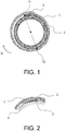
- Fig. 1 illustrates a schematic side surface view for describing the method for production according to the present embodiment.
- a rubber tape 3 is bonded to a winding ring 2, and a thin metal strip 1 is wound therearound.
- the reason for using a rubber tape in the present embodiment is to fix the thin metal strip thereto using a frictional force of the rubber tape so that the wound thin metal strip does not slip from the surface of the winding ring.
- a static friction coefficient of the rubber tape that can be applied to the present embodiment here is set to 3.0 or higher, and a high friction resistance material is preferably used therefor.
- a static friction coefficient is more preferably 4.0 or higher, and even more preferably 5.0 or higher.
- the rubber tape used in the present embodiment can be applied to a generally used winding ring regardless of a material or a surface roughness of the winding ring as long as a rubber tape can be bonded to the winding ring.
- the present invention is particularly effective for a roll made of a metal without a step or irregularity that is greater than or equal to a thickness of a thin plate to be applied.
- the rubber tape of the present embodiment has a base material made of rubber and an adhesive layer formed on one surface of the base material.
- a material of the base material natural rubber, nitrile rubber, fluorine rubber, urethane rubber, silicone rubber, or the like can be used as long as it meets the requirements for the above-described static friction coefficient.
- silicone rubber with which an adhesive effect is able to be exhibited without causing failures of slipping or the like even for a thin metal strip coated with processing oil or anti-rust oil has a moderate elastic force that is sufficient for preventing the thin metal strip from deforming, and is affordable at a low cost, is used.
- a thickness of the rubber tape is preferably set to 0.5 mm or less.
- a thickness thereof is more preferably set to 0.2 mm or less, which enables a deformation curbing effect to be increased.
- a thickness thereof is even more preferably 0.1 mm or less.
- a thickness of the rubber tape set to 0.05 mm or greater may impart sufficient rigidity to the tape and improve deformation resistance, and thus it is preferable. Therefore, a thickness of the tape is preferably 0.05 to 0.5 mm.
- a thickness of the tape can be changed depending on a material type of the thin metal strip, and a thickness of the tape is preferably set to be thick (over 0.2 mm and 0.5 mm or less) in a range from 0.05 mm to 0.5 mm, for example, for a thin metal strip with a high hardness (e.g., 200 HV or greater).
- a structure of the rubber tape a structure in which a side bonded to the winding ring has an adhesive and a surface in contact with the thin metal strip is rubber is preferably used.
- a composite tape using a film or the like in an intermediate layer or a self-fusing rubber tape may be applied.
- a length of the rubber tape in a width direction (corresponding to a width direction of the thin metal strip) used in the present embodiment can be appropriately adjusted in accordance with a width of the thin metal strip to be wound.
- the rubber tape of the present embodiment is used, although effects can be exhibited regardless of a width of the thin metal strip to be wound due to a frictional force, a tape mark is likely to be generated depending on a material of the thin metal strip, and thus a width as close as possible to a width of the thin metal strip to be wound is preferable.
- a width of the thin metal strip to be wound is set to X mm and a length of the rubber tape in the width direction is set to 0.7X to X mm, the effects of the present invention can be sufficiently exhibited.
- a lower limit of a length thereof in the width direction is preferably 0.8X mm.
- a length of the rubber tape of the present embodiment in a circumferential direction (corresponding to a length direction of the thin metal strip) can be appropriately adjusted in accordance with a size of the rubber tape or a material type of the thin metal strip such that it can be fixed due to a frictional force generated on the contact surface between the rubber tape and the thin metal strip. Meanwhile, when the rubber tape is bonded to the entire circumference of the winding ring, a sufficient frictional force is ensured, however, a binding force to the thin metal strip is likely to be excessively strong.
- a length of the rubber tape is preferably set to be less than 10% of a perimeter of the winding ring.
- a length thereof is more preferably set to 5% or less and even more preferably 3% or less than the perimeter of the ring.
- the thin metal strip to be wound is preferably wound such that a peripheral portion of the tip thereof is adjusted to come in contact with the rubber tape.
- Fig. 2 illustrates a schematic view of a peripheral portion of a tip of the thin metal strip of the present embodiment.
- that represented by reference numeral 4 is a tip of the thin metal strip according to the present embodiment.
- the peripheral portion of the tip of the thin metal strip refers to the range from the tip (point P in Fig. 1 ) of the thin metal strip that has been wound around the winding ring to the position (point Q in Fig.
- the arc PQ tracing the first layer of the thin metal strip in the R direction is "the peripheral portion of the tip of the thin metal strip" and it is preferable for at least a part of the arc PQ (the peripheral portion of the tip of the thin metal strip) to be disposed to come in contact with the rubber tape 3.
- a high quality thin metal strip coil with curbed scratches or bending that may occur in the innermost circumferential part of the coil can be obtained while reducing production costs.
- a more preferable position of the point Q is in the range from the point P to the point corresponding to 1/4 of the circumference (90°), and an even more preferable position is in the range from the point P to the point corresponding to 1/5 of the circumference (72°).
- tape dimensions (a thickness of 0.1 mm ⁇ a width of 20 mm), winding rings (iron rings with a perimeter of ⁇ 280 mm), and thin metal strips to be wound (martensitic stainless steel with a thickness of 0.1 mm ⁇ a width of 25 mm) were made uniform.
- a length of the tapes was set to 20 mm, the tapes were bonded to winding rings such that the tips of the tapes were located at the position 10 mm away from the tips of the thin metal strips to be wound in the winding direction (the R direction in Fig. 1 ), and then the thin metal strips were wound therearound.
- the thin metal strips were manually wound twice therearound in advance and wound over 30 meters with a winding tension set value set to 20 N.
- Static friction coefficients of each of the tapes were measured in advance in a method based on JIS-K-7125. The measurement results are also shown in Table 1. The results obtained by performing the winding evaluation three times are shown in Table 1.
- the tape thickness, the material of the thin metal strip, the plate thickness of the thin metal strip, the presence/absence of anti-rust oil, the material of the winding ring, and a tape bonding method were varied to ascertain conditions for satisfactorily winding the thin metal strip.
- the arithmetic mean roughness Ra of the thin metal strips were checked in advance at an evaluation length of 4 mm in accordance with the measurement method defined in JIS-B-0601. The result was that it was ascertained that all thin plates had a roughness Ra of 0.6 ⁇ m or less.
- the thin metal strips were manually wound two laps in advance and wound for 4000 meters with a winding tension set value set to 20 N.
- a winding evaluation for confirming the presence or absence of slipping, and a quality evaluation for confirming the quality of winding, and the presence or absence of defects in the thin metal strip on the innermost circumferential part were performed by unwinding the wound thin metal strip.
- Table 2 shows the conditions and evaluation results thereof.
- example 2-16 in which the silicone tape was bonded to the entire circumference of the ring as a tape bonding method, winding was favorably performed and improvement in comparison to comparative example 2-1 was recognized. Meanwhile, while the thin metal strip was wound, misalignment of the width of the thin metal strip occurred around the inner circumference. In addition, as a result of checking the thin metal strip at the innermost circumferential part by rewinding the wound thin metal strip, deformation of the thin metal strip on the inner circumference caused by width misalignment occurred.
Landscapes
- Engineering & Computer Science (AREA)
- Mechanical Engineering (AREA)
- Winding, Rewinding, Material Storage Devices (AREA)
- Storage Of Web-Like Or Filamentary Materials (AREA)
- Pressure Welding/Diffusion-Bonding (AREA)
- Winding Of Webs (AREA)
Abstract
Description
- The present invention relates to a method for producing a thin metal strip coil and a thin metal strip coil obtained by winding a thin metal strip around a winding ring.
- A strip-shaped thin metal plate (thin metal strip) rolled using a rolling machine or the like to have a predetermined thickness is little used as a final product as is, and is subjected to secondary processing, for example, pressing, punching, bending/drawing, etching, or the like, to be molded into a final product to be used in a variety of industrial fields. Such a thin metal strip is generally wound around a ring-shaped reel (which will also be referred to as a winding ring below) and transported to the next processing in the form of a thin metal strip coil. Typical methods of fixing such a thin metal strip to a winding ring include a method of bonding a tip of a thin metal strip directly to a winding ring using tape, a method of roughening an outer circumferential surface of a winding ring by performing knurling or shot blasting, a method of making a slit groove in a winding ring and inserting a tip of a thin metal strip thereinto, and the like.
- In addition,
Patent Literature 1 discloses a steel strip winding method in which, in order to reduce a fold (which will also referred to as set bending or a top mark) of the tip of a steel strip, a rubber sleeve having a substantially strip-shaped soft layer, which is formed of a softer elastic material than the main body of the rubber sleeve on an outer circumference in the longitudinal direction of the rubber sleeve is used, and the tip of the steel strip is positioned in a range of the soft layer of the rubber sleeve. In addition,Patent Literature 2 discloses a long object winding frame having a metal cylinder as the core with an outer circumferential surface coated with a resin layer to wind up a metal plate into a coil shape without slip from and damage to the surface when the metal plate is wound. -
- [Patent Literature 1]
Japanese Patent Laid-Open No.H7-16648 - [Patent Literature 2]
Japanese Patent Laid-Open No.H11-165955 - Such a thin metal strip described above is required to have a good surface quality to enable the thin metal strip wound in a coil shape to be used up to the tip thereof, in addition to avoid a problem arising during secondary processing. However, in the winding method of the related art, an innermost circumferential part of the wound thin metal strip is susceptible to scratches, deformation, or the like, and thus the thin metal strip is unlikely to be used up to the tip. Such scratches and deformation tend to occur as a plate becomes thinner, and in the above-described
Patent Literature 1, a plate thickness of the example is 0.8 mm, for example, a thin metal strip having a thin plate thickness of 0.3 mm or less is not discussed, and there is no proposal for a means for curbing scratches or deformation that is likely to occur in the innermost circumferential part of the thin metal strip wound into a coil shape. In addition, even if such a proposal had been made, a structure or a means would be complicated as inPatent Literature 2, and thus problems of high production costs and deterioration in workability and maintenance properties would arise. - An objective of the present invention is to provide a method for producing a thin metal strip coil and a thin metal strip coil in which scratches and deformation that are likely to occur when a thin metal strip having a thin thickness of 0.3 mm or less is wound around a winding ring are curbed, with a low production cost, good workability, and good maintenance properties.
- An aspect of the present invention is a method for producing a thin metal strip coil of winding a thin metal strip around a winding ring to obtain a thin metal strip coil in which a thin metal strip having a plate thickness of 0.3 mm or less is wound around the winding ring having at least a part of an outer circumferential surface to which a high friction resistance material that is formed of a rubber tape is bonded.
- Preferably, the rubber tape has a static friction coefficient of 3.0 or higher.
- Preferably, a base material made of rubber of the rubber tape is made of silicone rubber.
- Preferably, the rubber tape has a base material made of rubber and an adhesive layer formed on one surface of the base material, and the rubber tape has an adhesive layer side bonded to the winding ring and a surface that comes in contact with the thin metal strip being the rubber base material.
- Preferably, a thickness of the rubber tape is 0.05 to 0.5 mm.
- Preferably, the thin metal strip is wound such that a peripheral portion of a tip of the thin metal strip comes in contact with the rubber tape.
- Another aspect of the present invention is a thin metal strip coil obtained by winding a thin metal strip around a winding ring, in which a plate thickness of the thin metal strip is 0.3 mm or less, and a high friction resistance material that is formed of a rubber tape is bonded to at least a part of an outer circumferential surface of the winding ring.
- Preferably, the rubber tape has a static friction coefficient of 3.0 or higher.
- Preferably, a base material made of rubber of the rubber tape is made of silicone rubber.
- Preferably, the rubber tape has a base material made of rubber and an adhesive layer formed on one surface of the base material, and the rubber tape has an adhesive layer side bonded to the winding ring and a surface that comes in contact with the thin metal strip being the rubber base material.
- Preferably, a thickness of the rubber tape is 0.05 to 0.5 mm.
- Preferably, in a range from a tip for beginning winding of the thin metal strip to half a circumference of the winding ring, the high friction resistance material that is formed of the rubber tape is bonded to at least a part of the outer circumferential surface of the winding ring.
- According to the present invention, when a thin metal strip having a plate thickness of 0.3 mm or less is wound in a coil shape, it is possible to obtain a good-quality thin metal strip coil in which scratches and deformation that are likely to occur in an innermost circumferential part of the coil are curbed while reducing a production cost.
-
-
Fig. 1 is a schematic side view for describing a method for production of the present invention. -
Fig. 2 is an enlarged view of a peripheral portion of a tip of a thin strip ofFig. 1 . - An embodiment of the present invention will be described below.
- A plate thickness of a thin metal strip that is a subject of the present invention is set to 0.3 mm or less. When a plate thickness of the thin metal strip is adjusted such that it is within the above-described range, the thin metal strip can be stably wound around a winding ring due to a frictional force of a rubber tape, which will be described below. A plate thickness is preferably 0.2 mm or less, and more preferably 0.1 mm or less. In addition, although no particular lower limit value is defined, when a plate thickness is extremely thin, set bending at the tip cannot be prevented, and deformation of the thin metal strip is highly likely to occur, and therefore, a plate thickness is preferably set to 0.03 mm or greater. When a plate thickness of the thin metal strip exceeds 0.3 mm and the thin metal strip is wound around a winding ring to which a high friction resistance material is bonded, it tends to be difficult to wind the thin metal strip around the winding ring due to an elastic force of the thin metal strip depending on a material of the thin metal strip. In addition, a surface roughness of the thin metal strip is preferably set to an arithmetic mean roughness Ra defined by JIS-B-0601 of 0.6 µm or less. When a surface roughness of the thin metal strip is excessively high, a contact area with the rubber tape becomes small, and thus the thin metal strip tends to have a lower frictional force, but when the surface roughness is adjusted to be within the above-described range of Ra, a more stable frictional force with respect to the rubber tape tends to be obtained. As a surface roughness becomes lower, a contact area with the rubber tape increases and a frictional force becomes higher, which is a trend in which the effects of the invention are more likely to be exhibited. Thus, a surface roughness Ra is more preferably 0.3 µm or less, and even more preferably 0.2 µm or less. A lower limit value of a surface roughness is not particularly limited, and may be set to, for example, Ra of 0.001 µm or greater. A "metal" to be applied to the present invention may be selected from, as examples, steel such as carbon steel, stainless steel, and alloy steel and non-ferrous metals such as aluminum, titanium, copper, and zinc, or may be an alloy of the above-described metals. In addition, the method for production of the present invention can be applied to a material obtained by joining (pressure welding, welding, or brazing) a first metal with a dissimilar material other than the first metal.
- In the present embodiment, a high friction resistance material formed of a rubber tape is bonded to an outer circumferential surface of a winding ring (a surface on which a thin metal strip is wound).
Fig. 1 illustrates a schematic side surface view for describing the method for production according to the present embodiment. In the present embodiment illustrated inFig. 1 , arubber tape 3 is bonded to a windingring 2, and athin metal strip 1 is wound therearound. The reason for using a rubber tape in the present embodiment is to fix the thin metal strip thereto using a frictional force of the rubber tape so that the wound thin metal strip does not slip from the surface of the winding ring. A static friction coefficient of the rubber tape that can be applied to the present embodiment here is set to 3.0 or higher, and a high friction resistance material is preferably used therefor. A static friction coefficient is more preferably 4.0 or higher, and even more preferably 5.0 or higher. The occurrence of scratches caused by slipping of the thin metal strip due to a frictional force of the rubber tape and failure (deformation) such as bending when the thin metal strip is set on the winding ring can be avoided. In addition, a complicated mechanism is not necessary, and since an effect of fixing the thin metal strip onto the outer circumferential surface of the winding ring is obtained simply by bonding the rubber tape to the outer circumferential surface, the workability is excellent. Furthermore, since good maintenance properties can be obtained due to the replaceable rubber tape, it is possible to reuse the winding ring repeatedly, and thus the thin metal strip can be used to the tip with good quality while curbing any increase in costs. In addition, no adhesive is applied to the surface with which the thin metal strip comes in contact because the thin metal strip is fixed thereto with a frictional force of the rubber tape, damage to a press mold and etching failure caused by a remaining adhesive on the thin metal strip as well as a line problem that may occur due to the thin metal strip not separating from the winding ring can be prevented, and therefore more advantageous effects than those of a method for fixation in the related art can be exhibited. The rubber tape used in the present embodiment can be applied to a generally used winding ring regardless of a material or a surface roughness of the winding ring as long as a rubber tape can be bonded to the winding ring. The present invention is particularly effective for a roll made of a metal without a step or irregularity that is greater than or equal to a thickness of a thin plate to be applied. - The rubber tape of the present embodiment has a base material made of rubber and an adhesive layer formed on one surface of the base material. As a material of the base material, natural rubber, nitrile rubber, fluorine rubber, urethane rubber, silicone rubber, or the like can be used as long as it meets the requirements for the above-described static friction coefficient. Preferably, silicone rubber with which an adhesive effect is able to be exhibited without causing failures of slipping or the like even for a thin metal strip coated with processing oil or anti-rust oil, has a moderate elastic force that is sufficient for preventing the thin metal strip from deforming, and is affordable at a low cost, is used. When a material other than a rubber tape such as paper, fabric, any of various plastic film (PE, PET, PVC, or the like), or a metal tape is used for a base material of an adhesive tape, a frictional force with respect to the thin metal strip tends to be lower and slip tends to occur.
- When the rubber tape used in the present embodiment has an excessive tape thickness, the thin metal strip that is wound around the rubber tape is likely to deform, and thus a thickness of the rubber tape is preferably set to 0.5 mm or less. A thickness thereof is more preferably set to 0.2 mm or less, which enables a deformation curbing effect to be increased. A thickness thereof is even more preferably 0.1 mm or less. In addition, a thickness of the rubber tape set to 0.05 mm or greater may impart sufficient rigidity to the tape and improve deformation resistance, and thus it is preferable. Therefore, a thickness of the tape is preferably 0.05 to 0.5 mm. A thickness of the tape can be changed depending on a material type of the thin metal strip, and a thickness of the tape is preferably set to be thick (over 0.2 mm and 0.5 mm or less) in a range from 0.05 mm to 0.5 mm, for example, for a thin metal strip with a high hardness (e.g., 200 HV or greater). As a structure of the rubber tape, a structure in which a side bonded to the winding ring has an adhesive and a surface in contact with the thin metal strip is rubber is preferably used. In addition, a composite tape using a film or the like in an intermediate layer or a self-fusing rubber tape may be applied.
- A length of the rubber tape in a width direction (corresponding to a width direction of the thin metal strip) used in the present embodiment can be appropriately adjusted in accordance with a width of the thin metal strip to be wound. When the rubber tape of the present embodiment is used, although effects can be exhibited regardless of a width of the thin metal strip to be wound due to a frictional force, a tape mark is likely to be generated depending on a material of the thin metal strip, and thus a width as close as possible to a width of the thin metal strip to be wound is preferable. Specifically, when a width of the thin metal strip to be wound is set to X mm and a length of the rubber tape in the width direction is set to 0.7X to X mm, the effects of the present invention can be sufficiently exhibited. Furthermore, a lower limit of a length thereof in the width direction is preferably 0.8X mm.
- A length of the rubber tape of the present embodiment in a circumferential direction (corresponding to a length direction of the thin metal strip) can be appropriately adjusted in accordance with a size of the rubber tape or a material type of the thin metal strip such that it can be fixed due to a frictional force generated on the contact surface between the rubber tape and the thin metal strip. Meanwhile, when the rubber tape is bonded to the entire circumference of the winding ring, a sufficient frictional force is ensured, however, a binding force to the thin metal strip is likely to be excessively strong. For this reason, when the thin metal strip is set to be slightly misaligned with the winding ring in the width direction when the thin metal strip is set on the winding ring, the thin metal strip is wound with the width misalignment in the innermost circumferential part unmodified due to the excessively strong binding force, and thus failure in winding or deformation is likely to be caused. For this reason, a length of the rubber tape is preferably set to be less than 10% of a perimeter of the winding ring. A length thereof is more preferably set to 5% or less and even more preferably 3% or less than the perimeter of the ring.
- In addition, in the present embodiment, the thin metal strip to be wound is preferably wound such that a peripheral portion of the tip thereof is adjusted to come in contact with the rubber tape.
Fig. 2 illustrates a schematic view of a peripheral portion of a tip of the thin metal strip of the present embodiment. InFig. 2 , that represented byreference numeral 4 is a tip of the thin metal strip according to the present embodiment. Because the tip of the thin metal strip is reasonably close to the position of the rubber tape, resistance to set bending of the tip can be improved and winding work can be easier. Here, the peripheral portion of the tip of the thin metal strip refers to the range from the tip (point P inFig. 1 ) of the thin metal strip that has been wound around the winding ring to the position (point Q inFig. 1 ) of the thin metal strip advanced halfway around the outer circumference of the winding ring in the winding direction (direction R inFig. 1 ) of the thin metal strip. That is, inFig. 1 , the arc PQ tracing the first layer of the thin metal strip in the R direction (clockwise) is "the peripheral portion of the tip of the thin metal strip" and it is preferable for at least a part of the arc PQ (the peripheral portion of the tip of the thin metal strip) to be disposed to come in contact with therubber tape 3. Thus, when producing a thin metal strip coil obtained by winding the thin metal strip with a thickness adjusted to be in a predetermined thickness range, a high quality thin metal strip coil with curbed scratches or bending that may occur in the innermost circumferential part of the coil can be obtained while reducing production costs. A more preferable position of the point Q is in the range from the point P to the point corresponding to 1/4 of the circumference (90°), and an even more preferable position is in the range from the point P to the point corresponding to 1/5 of the circumference (72°). Although the effects of the present invention can be exhibited when the rubber tape comes in contact with the tip of the thin metal strip as described above, it is more preferable for the entire rubber tape to be disposed to be included in the peripheral portion of the tip. - The present invention will be described in more detail in the following examples.
- First, various tape materials shown in Table 1 were prepared, the tapes were bonded to the outer circumferential surfaces of winding rings, thin metal strips were wound around the winding rings, whether the thin metal strips slipped was observed, and thereby the winding was evaluated. To evaluate winding of the various tape materials, tape dimensions (a thickness of 0.1 mm × a width of 20 mm), winding rings (iron rings with a perimeter of ϕ280 mm), and thin metal strips to be wound (martensitic stainless steel with a thickness of 0.1 mm × a width of 25 mm) were made uniform. A length of the tapes was set to 20 mm, the tapes were bonded to winding rings such that the tips of the tapes were located at the position 10 mm away from the tips of the thin metal strips to be wound in the winding direction (the R direction in
Fig. 1 ), and then the thin metal strips were wound therearound. After the winding rings were set in a winding device, the thin metal strips were manually wound twice therearound in advance and wound over 30 meters with a winding tension set value set to 20 N. Static friction coefficients of each of the tapes were measured in advance in a method based on JIS-K-7125. The measurement results are also shown in Table 1. The results obtained by performing the winding evaluation three times are shown in Table 1. It was confirmed that, when a silicone tape, which is a present invention example, was applied, winding was satisfactorily performed with no occurrence of slip in all three tests, and thus the effects of a high friction resistance material were exhibited. In contrast, slip occurred in all three tests with examples other than the present invention example, and thus in these cases it was not possible to fix the thin metal strips to the winding rings.[Table 1] Tape materials Winding evaluation (whether slip occurred) Static friction coefficient Remarks First test Second test Third test Silicone tape ○ ○ ○ 5.79 Present invention example 1-1 PE film tape X X X 0.39 Comparative example 1-1 PET film tape X X X 0.37 Comparative example 1-2 Masking tape X X X 0.44 Comparative example 1-3 PVC tape X X X 1.66 Comparative example 1-4 - Next, using silicone tapes, the tape thickness, the material of the thin metal strip, the plate thickness of the thin metal strip, the presence/absence of anti-rust oil, the material of the winding ring, and a tape bonding method were varied to ascertain conditions for satisfactorily winding the thin metal strip. The arithmetic mean roughness Ra of the thin metal strips were checked in advance at an evaluation length of 4 mm in accordance with the measurement method defined in JIS-B-0601. The result was that it was ascertained that all thin plates had a roughness Ra of 0.6 µm or less. After a tape length was set to 20 mm and winding rings were set for winding using the above-mentioned winding device, the thin metal strips were manually wound two laps in advance and wound for 4000 meters with a winding tension set value set to 20 N. For the evaluation, a winding evaluation for confirming the presence or absence of slipping, and a quality evaluation for confirming the quality of winding, and the presence or absence of defects in the thin metal strip on the innermost circumferential part were performed by unwinding the wound thin metal strip. Table 2 shows the conditions and evaluation results thereof. As a result of measuring hardness of the various thin metal strips in advance, stainless steel had a hardness of 300 HV, a Fe-Ni alloy had a hardness of 190 HV, and a Cu alloy had a hardness of 160 HV. In addition, the "peripheral portion of the tip" in the "bonding position" in Table 2 represents a "position 10 mm away from the tips of the thin metal strips to be wound" as in Example 1, and the "position at 180° from the tip" in the bonding position of present invention example 2017 represents a "position at which the thin metal strip has advanced half the circumferential length of the winding ring from the tip of the thin metal strip in the winding direction (R direction)."
[Table 2] Tape thickness (mm) Thin metal strip Presence/absence of anti-rust oil Ring material Bonding position Winding evaluation (occurrence of slip) Quality evaluation (scratches, bending, deformation, etc.) Remarks Material Plate thickness (mm) 0.1 Stainless steel 0.1 None Iron Peripheral portion of tip ○ ○ Present invention example 2-1 0.15 Stainless steel 0.1 None Iron Peripheral portion of tip ○ ○ Present invention example 2-2 0.2 Stainless steel 0.1 N one Iron Peripheral portion of tip ○ ○ Present invention example 2-3 0.1 Fe-Ni alloy 0.1 None Iron Peripheral portion of tip ○ ○ Present invention example 2-4 0.1 Cu alloy 0.1 None Iron Peripheral portion of tip ○ ○ Present invention example 2-5 0.1 Stainless steel 0.15 None Iron Peripheral portion of tip ○ ○ Present invention example 2-6 0.1 Stainless steel 0.08 None Iron Peripheral portion of tip ○ ○ Present invention example 2-7 0.1 Fe-Ni alloy 0.05 None Iron Peripheral portion of tip ○ ○ Present invention example 2-8 0.1 Stainless steel 0.08 Present Iron Peripheral portion of tip ○ ○ Present invention example 2-9 0.1 Stainless steel 0.1 Present Iron Peripheral portion of tip ○ ○ Present invention example 2-10 0.1 Stainless steel 0.1 None Plastic Peripheral portion of tip ○ ○ Present invention example 2-11 0.1 Stainless steel 0.1 None Paper pipe Peripheral portion of tip ○ ○ Present invention example 2-12 0.4 Stainless steel 0.1 None Iron Peripheral portion of tip ○ ○ Present invention example 2-13 0.4 Fe-Ni alloy 0.1 None Iron Peripheral portion of tip ○ Δ (Tape irregularity) Present invention example 2-14 0.4 Cu alloy 0.1 None Iron Peripheral portion of tip ○ Δ (Tape irregularity) Present invention example 2-15 0.1 Stainless steel 0.1 None Iron Entire ring circumference ○ Δ (Winding failure) Present invention example 2-16 0.1 Stainless steel 0.1 None Iron Position at 180° from tip ○ Δ (Tip overhung) Present invention example 2-17 0.1 Stainless steel 0.38 None Iron Peripheral portion of tip X (Rebound occurred) - Comparative example 2-1 - When the thin metal strips were compared in terms of tape thickness, winding evaluation and quality evaluation were good regardless of materials of the thin metal strips as indicated in the present invention examples 2-1 to 2-5. Even when the tape thickness of stainless steel of the present invention example 2-13 was set to 0.4 mm, winding evaluation and quality evaluation were good. When a tape thickness of the thin metal strips having a hardness of 200 HV or less as indicated in the present invention examples 2-14 and 2-15 was set to 0.4 mm, the strip was wound without slip and winding evaluation was good, but tape irregularity occurred. According to the other results for the present invention examples, it is thought that, when a hardness was 200 HV or less, the quality could have been further improved by setting the plate thickness of the tape to 0.2 mm or less.
- In terms of plate thickness of the thin metal strips, products having a thick plate thickness as indicated in the present invention example 2-6 and the thin metal strips having a thin plate thickness as indicated in the present invention examples 2-7 and 2-8 exhibited good winding and quality evaluation. However, in Comparative example 2-1 having a plate thickness of 0.38 mm, the elastic force of the thin metal strip was strong, and the thin metal strip rebounded, which made winding difficult.
- As a result of evaluating the thin metal strips (present invention examples 2-9 and 2-10) with anti-rust oil on surfaces, winding and quality evaluation were good even though anti-rust oil was applied on the surfaces of the thin metal strip. In addition, even in the present invention examples 2-11 and 2-12 in which ring materials were changed, the silicone tapes were bonded and thus evaluation was good.
- In the present invention example 2-16 in which the silicone tape was bonded to the entire circumference of the ring as a tape bonding method, winding was favorably performed and improvement in comparison to comparative example 2-1 was recognized. Meanwhile, while the thin metal strip was wound, misalignment of the width of the thin metal strip occurred around the inner circumference. In addition, as a result of checking the thin metal strip at the innermost circumferential part by rewinding the wound thin metal strip, deformation of the thin metal strip on the inner circumference caused by width misalignment occurred. Next, also in the present invention example 2-17 in which the tape was bonded to a position 180° away from the tip of the thin metal strip in the inner circumferential direction, winding was favorably performed and improvement in comparison to comparative example 2-1 was recognized, but the tip overhung.
- It has been ascertained from the above configuration that, only by bonding a rubber tape to an outer circumferential surface of a winding ring with the present invention applied and no complicated structure required, scratches caused by slip of a thin metal strip that may occur in an innermost circumference in winding can be prevented, set bending of the thin metal strip can be curbed due to a cushioning property of the rubber tape, and the present invention can be applied when a thin metal strip coil made of a wide variety of materials is produced.
-
- 1
- Thin metal strip
- 2
- Winding ring
- 3
- Rubber tape
- 4
- Tip of thin metal strip
Claims (12)
- A method for producing a thin metal strip coil of winding a thin metal strip around a winding ring to obtain a thin metal strip coil, the method comprising:
winding a thin metal strip having a plate thickness of 0.3 mm or less around the winding ring having at least a part of an outer circumferential surface to which a high friction resistance material that is formed of a rubber tape is bonded. - The method for producing a thin metal strip coil according to claim 1, wherein the rubber tape has a static friction coefficient of 3.0 or higher.
- The method for producing a thin metal strip coil according to claim 1 or 2, wherein a base material made of rubber of the rubber tape is made of silicone rubber.
- The method for producing a thin metal strip coil according to any one of claims 1 to 3,
wherein the rubber tape has a base material made of rubber and an adhesive layer formed on one surface of the base material, and
the rubber tape has an adhesive layer side bonded to the winding ring and a surface that comes in contact with the thin metal strip being the rubber base material. - The method for producing a thin metal strip coil according to any one of claims 1 to 4, wherein a thickness of the rubber tape is 0.05 to 0.5 mm.
- The method for producing a thin metal strip coil according to any one of claims 1 to 5, wherein the thin metal strip is wound such that a peripheral portion of a tip of the thin metal strip comes in contact with the rubber tape.
- A thin metal strip coil obtained by winding a thin metal strip around a winding ring,
wherein a plate thickness of the thin metal strip is 0.3 mm or less, and
a high friction resistance material that is formed of a rubber tape is bonded to at least a part of an outer circumferential surface of the winding ring. - The thin metal strip coil according to claim 7, wherein the rubber tape has a static friction coefficient of 3.0 or higher.
- The thin metal strip coil according to claim 7 or 8, wherein a base material made of rubber of the rubber tape is made of silicone rubber.
- The thin metal strip coil according to any one of claims 7 to 9,
Wherein the rubber tape has a base material made of rubber and an adhesive layer formed on one surface of the base material, and
The rubber tape has an adhesive layer side bonded to the winding ring and a surface that comes in contact with the thin metal strip being the rubber base material. - The thin metal strip coil according to any one of claims 7 to 10, wherein a thickness of the rubber tape is 0.05 to 0.5 mm.
- The thin metal strip coil according to any one of claims 7 to 11, wherein, in a range from a tip for beginning winding of the thin metal strip to half a circumference of the winding ring, the high friction resistance material that is formed of the rubber tape is bonded to at least a part of the outer circumferential surface of the winding ring.
Applications Claiming Priority (2)
| Application Number | Priority Date | Filing Date | Title |
|---|---|---|---|
| JP2018025558 | 2018-02-16 | ||
| PCT/JP2019/005115 WO2019159970A1 (en) | 2018-02-16 | 2019-02-13 | Method for producing metal thin strip coil, and metal thin strip coil |
Publications (3)
| Publication Number | Publication Date |
|---|---|
| EP3753643A1 true EP3753643A1 (en) | 2020-12-23 |
| EP3753643A4 EP3753643A4 (en) | 2021-11-17 |
| EP3753643B1 EP3753643B1 (en) | 2023-06-07 |
Family
ID=67619533
Family Applications (1)
| Application Number | Title | Priority Date | Filing Date |
|---|---|---|---|
| EP19754242.6A Active EP3753643B1 (en) | 2018-02-16 | 2019-02-13 | Method for producing metal thin strip coil, and metal thin strip coil |
Country Status (7)
| Country | Link |
|---|---|
| EP (1) | EP3753643B1 (en) |
| JP (1) | JP7248006B2 (en) |
| CN (1) | CN111788017B (en) |
| MY (1) | MY199212A (en) |
| PL (1) | PL3753643T3 (en) |
| SG (1) | SG11202007695YA (en) |
| WO (1) | WO2019159970A1 (en) |
Family Cites Families (18)
| Publication number | Priority date | Publication date | Assignee | Title |
|---|---|---|---|---|
| JPS4835255Y1 (en) * | 1969-07-18 | 1973-10-24 | ||
| JPS59147713A (en) * | 1983-02-14 | 1984-08-24 | Kawasaki Steel Corp | Taking-up method of thin strip |
| FR2661962B1 (en) * | 1990-05-09 | 1992-07-17 | Auxmet | BELT, PARTICULARLY FOR A BRAKING DEVICE OF A METAL BELT SLITTING SYSTEM. |
| JP3266935B2 (en) * | 1991-08-28 | 2002-03-18 | 住友金属工業株式会社 | Winding mandrel and winding device and method |
| JPH05285540A (en) * | 1992-04-09 | 1993-11-02 | Kawasaki Steel Corp | Method for preventing top mark of belt-like material and take-up bubber sleeve used for its method |
| JPH0671337A (en) * | 1992-08-27 | 1994-03-15 | Nkk Corp | Winding method for steel sheet |
| JPH0716648A (en) | 1993-06-30 | 1995-01-20 | Kawasaki Steel Corp | Winding method of metal strip |
| JPH07124646A (en) * | 1993-10-29 | 1995-05-16 | Kawasaki Steel Corp | Winding method for steel strip and rubber sleeve used therefor |
| JPH11165955A (en) * | 1997-12-03 | 1999-06-22 | Ootsu Chemical Kk | Long object take-up frame and method of manufacturing the same |
| JP2002114418A (en) * | 2000-10-03 | 2002-04-16 | Fuji Photo Film Co Ltd | Winding method of photosensitive lithographic printing plate and paper tube for winding |
| JP2002113518A (en) * | 2000-10-04 | 2002-04-16 | Nisshin Steel Co Ltd | Rubber sleeve for winding metal band |
| JP2003211220A (en) * | 2002-01-22 | 2003-07-29 | Jfe Engineering Kk | Rubber sleeve for winding metal band and method for winding metal band |
| JP3947845B2 (en) * | 2002-10-07 | 2007-07-25 | 株式会社テクノ月星 | Rubber sleeve for winding metal band |
| JP2006281302A (en) * | 2005-04-04 | 2006-10-19 | Sumitomo Metal Ind Ltd | Winding method of thin steel strip |
| DE102009055374A1 (en) * | 2009-12-29 | 2011-06-30 | Voith Patent GmbH, 89522 | Reel winding device |
| CN102161452B (en) * | 2011-03-02 | 2013-04-10 | 梅县金象铜箔有限公司 | Rewinding shaft for electrolytic copper foil production and using method thereof |
| CN103159076A (en) * | 2011-12-08 | 2013-06-19 | 张春宇 | Winder |
| CN205413962U (en) * | 2016-03-01 | 2016-08-03 | 攀钢集团攀枝花钢钒有限公司 | Metal band coiling apparatus |
-
2019
- 2019-02-13 WO PCT/JP2019/005115 patent/WO2019159970A1/en not_active Ceased
- 2019-02-13 MY MYPI2020004117A patent/MY199212A/en unknown
- 2019-02-13 SG SG11202007695YA patent/SG11202007695YA/en unknown
- 2019-02-13 JP JP2020500521A patent/JP7248006B2/en active Active
- 2019-02-13 PL PL19754242.6T patent/PL3753643T3/en unknown
- 2019-02-13 CN CN201980013292.3A patent/CN111788017B/en active Active
- 2019-02-13 EP EP19754242.6A patent/EP3753643B1/en active Active
Also Published As
| Publication number | Publication date |
|---|---|
| MY199212A (en) | 2023-10-19 |
| PL3753643T3 (en) | 2023-09-18 |
| WO2019159970A1 (en) | 2019-08-22 |
| JPWO2019159970A1 (en) | 2021-02-04 |
| EP3753643A4 (en) | 2021-11-17 |
| EP3753643B1 (en) | 2023-06-07 |
| CN111788017B (en) | 2022-08-30 |
| SG11202007695YA (en) | 2020-09-29 |
| JP7248006B2 (en) | 2023-03-29 |
| CN111788017A (en) | 2020-10-16 |
Similar Documents
| Publication | Publication Date | Title |
|---|---|---|
| EP3239998B1 (en) | Material for laminated iron core, and method of manufacturing laminated iron core | |
| TWI360511B (en) | ||
| CN102070048B (en) | The method for winding of band | |
| EP3753643B1 (en) | Method for producing metal thin strip coil, and metal thin strip coil | |
| US7065999B2 (en) | Bending roll apparatus | |
| JP2023088086A (en) | Winding core for web winding and web winding method | |
| JPH1071425A (en) | Winding method of metal strip | |
| JPH0289304A (en) | Method for cutting strap material for winding iron core | |
| JP3381629B2 (en) | Rubber sleeve for winding metal band and winding reel | |
| JP3702853B2 (en) | Winding method of thin steel strip | |
| JP3632391B2 (en) | Rubber sleeve for winding metal band | |
| JP2004283900A (en) | Steel sheet winding method | |
| JP3829858B2 (en) | Metal strip winding device and metal strip manufacturing method | |
| JP3403272B2 (en) | Winding method of steel strip | |
| US12496803B2 (en) | Multilayer magnetic sheet | |
| KR101373137B1 (en) | Sleeve for preventing end-mark of steel plate and steel plate winding apparatus having the same | |
| JP4671718B2 (en) | Sleeve for tension reel | |
| JP2024122859A (en) | Coil inner diameter sagging correction member and method of manufacturing metal strip | |
| KR20230142337A (en) | Magnetic sheet, multilayer magnetic sheet, and magnetic sheet manufacturing method | |
| JP2025062955A (en) | Magnetic shield sheet | |
| JPH05285540A (en) | Method for preventing top mark of belt-like material and take-up bubber sleeve used for its method | |
| JPH0553717U (en) | Strip winding device | |
| JP2002308483A (en) | Core | |
| JP2006281302A (en) | Winding method of thin steel strip | |
| JPH04176111A (en) | Method and apparatus for taking-up magnetic material of wound core |
Legal Events
| Date | Code | Title | Description |
|---|---|---|---|
| STAA | Information on the status of an ep patent application or granted ep patent |
Free format text: STATUS: THE INTERNATIONAL PUBLICATION HAS BEEN MADE |
|
| PUAI | Public reference made under article 153(3) epc to a published international application that has entered the european phase |
Free format text: ORIGINAL CODE: 0009012 |
|
| STAA | Information on the status of an ep patent application or granted ep patent |
Free format text: STATUS: REQUEST FOR EXAMINATION WAS MADE |
|
| 17P | Request for examination filed |
Effective date: 20200810 |
|
| AK | Designated contracting states |
Kind code of ref document: A1 Designated state(s): AL AT BE BG CH CY CZ DE DK EE ES FI FR GB GR HR HU IE IS IT LI LT LU LV MC MK MT NL NO PL PT RO RS SE SI SK SM TR |
|
| AX | Request for extension of the european patent |
Extension state: BA ME |
|
| DAV | Request for validation of the european patent (deleted) | ||
| DAX | Request for extension of the european patent (deleted) | ||
| A4 | Supplementary search report drawn up and despatched |
Effective date: 20211018 |
|
| RIC1 | Information provided on ipc code assigned before grant |
Ipc: B65H 19/28 20060101ALI20211012BHEP Ipc: B65H 65/00 20060101ALI20211012BHEP Ipc: B21C 47/28 20060101AFI20211012BHEP |
|
| RIC1 | Information provided on ipc code assigned before grant |
Ipc: B65H 19/28 20060101ALI20220907BHEP Ipc: B65H 65/00 20060101ALI20220907BHEP Ipc: B21C 47/28 20060101AFI20220907BHEP |
|
| GRAP | Despatch of communication of intention to grant a patent |
Free format text: ORIGINAL CODE: EPIDOSNIGR1 |
|
| STAA | Information on the status of an ep patent application or granted ep patent |
Free format text: STATUS: GRANT OF PATENT IS INTENDED |
|
| INTG | Intention to grant announced |
Effective date: 20221219 |
|
| GRAS | Grant fee paid |
Free format text: ORIGINAL CODE: EPIDOSNIGR3 |
|
| GRAA | (expected) grant |
Free format text: ORIGINAL CODE: 0009210 |
|
| STAA | Information on the status of an ep patent application or granted ep patent |
Free format text: STATUS: THE PATENT HAS BEEN GRANTED |
|
| RAP3 | Party data changed (applicant data changed or rights of an application transferred) |
Owner name: PROTERIAL, LTD. |
|
| AK | Designated contracting states |
Kind code of ref document: B1 Designated state(s): AL AT BE BG CH CY CZ DE DK EE ES FI FR GB GR HR HU IE IS IT LI LT LU LV MC MK MT NL NO PL PT RO RS SE SI SK SM TR |
|
| REG | Reference to a national code |
Ref country code: GB Ref legal event code: FG4D |
|
| REG | Reference to a national code |
Ref country code: CH Ref legal event code: EP Ref country code: AT Ref legal event code: REF Ref document number: 1573441 Country of ref document: AT Kind code of ref document: T Effective date: 20230615 |
|
| REG | Reference to a national code |
Ref country code: DE Ref legal event code: R096 Ref document number: 602019030339 Country of ref document: DE |
|
| REG | Reference to a national code |
Ref country code: SE Ref legal event code: TRGR |
|
| REG | Reference to a national code |
Ref country code: LT Ref legal event code: MG9D |
|
| REG | Reference to a national code |
Ref country code: NL Ref legal event code: MP Effective date: 20230607 |
|
| PG25 | Lapsed in a contracting state [announced via postgrant information from national office to epo] |
Ref country code: NO Free format text: LAPSE BECAUSE OF FAILURE TO SUBMIT A TRANSLATION OF THE DESCRIPTION OR TO PAY THE FEE WITHIN THE PRESCRIBED TIME-LIMIT Effective date: 20230907 Ref country code: ES Free format text: LAPSE BECAUSE OF FAILURE TO SUBMIT A TRANSLATION OF THE DESCRIPTION OR TO PAY THE FEE WITHIN THE PRESCRIBED TIME-LIMIT Effective date: 20230607 |
|
| REG | Reference to a national code |
Ref country code: GR Ref legal event code: EP Ref document number: 20230401313 Country of ref document: GR Effective date: 20231010 |
|
| REG | Reference to a national code |
Ref country code: AT Ref legal event code: MK05 Ref document number: 1573441 Country of ref document: AT Kind code of ref document: T Effective date: 20230607 |
|
| PG25 | Lapsed in a contracting state [announced via postgrant information from national office to epo] |
Ref country code: RS Free format text: LAPSE BECAUSE OF FAILURE TO SUBMIT A TRANSLATION OF THE DESCRIPTION OR TO PAY THE FEE WITHIN THE PRESCRIBED TIME-LIMIT Effective date: 20230607 Ref country code: NL Free format text: LAPSE BECAUSE OF FAILURE TO SUBMIT A TRANSLATION OF THE DESCRIPTION OR TO PAY THE FEE WITHIN THE PRESCRIBED TIME-LIMIT Effective date: 20230607 Ref country code: LV Free format text: LAPSE BECAUSE OF FAILURE TO SUBMIT A TRANSLATION OF THE DESCRIPTION OR TO PAY THE FEE WITHIN THE PRESCRIBED TIME-LIMIT Effective date: 20230607 Ref country code: LT Free format text: LAPSE BECAUSE OF FAILURE TO SUBMIT A TRANSLATION OF THE DESCRIPTION OR TO PAY THE FEE WITHIN THE PRESCRIBED TIME-LIMIT Effective date: 20230607 Ref country code: HR Free format text: LAPSE BECAUSE OF FAILURE TO SUBMIT A TRANSLATION OF THE DESCRIPTION OR TO PAY THE FEE WITHIN THE PRESCRIBED TIME-LIMIT Effective date: 20230607 |
|
| PG25 | Lapsed in a contracting state [announced via postgrant information from national office to epo] |
Ref country code: FI Free format text: LAPSE BECAUSE OF FAILURE TO SUBMIT A TRANSLATION OF THE DESCRIPTION OR TO PAY THE FEE WITHIN THE PRESCRIBED TIME-LIMIT Effective date: 20230607 |
|
| PG25 | Lapsed in a contracting state [announced via postgrant information from national office to epo] |
Ref country code: SK Free format text: LAPSE BECAUSE OF FAILURE TO SUBMIT A TRANSLATION OF THE DESCRIPTION OR TO PAY THE FEE WITHIN THE PRESCRIBED TIME-LIMIT Effective date: 20230607 |
|
| PG25 | Lapsed in a contracting state [announced via postgrant information from national office to epo] |
Ref country code: IS Free format text: LAPSE BECAUSE OF FAILURE TO SUBMIT A TRANSLATION OF THE DESCRIPTION OR TO PAY THE FEE WITHIN THE PRESCRIBED TIME-LIMIT Effective date: 20231007 |
|
| PG25 | Lapsed in a contracting state [announced via postgrant information from national office to epo] |
Ref country code: SM Free format text: LAPSE BECAUSE OF FAILURE TO SUBMIT A TRANSLATION OF THE DESCRIPTION OR TO PAY THE FEE WITHIN THE PRESCRIBED TIME-LIMIT Effective date: 20230607 Ref country code: SK Free format text: LAPSE BECAUSE OF FAILURE TO SUBMIT A TRANSLATION OF THE DESCRIPTION OR TO PAY THE FEE WITHIN THE PRESCRIBED TIME-LIMIT Effective date: 20230607 Ref country code: RO Free format text: LAPSE BECAUSE OF FAILURE TO SUBMIT A TRANSLATION OF THE DESCRIPTION OR TO PAY THE FEE WITHIN THE PRESCRIBED TIME-LIMIT Effective date: 20230607 Ref country code: PT Free format text: LAPSE BECAUSE OF FAILURE TO SUBMIT A TRANSLATION OF THE DESCRIPTION OR TO PAY THE FEE WITHIN THE PRESCRIBED TIME-LIMIT Effective date: 20231009 Ref country code: IS Free format text: LAPSE BECAUSE OF FAILURE TO SUBMIT A TRANSLATION OF THE DESCRIPTION OR TO PAY THE FEE WITHIN THE PRESCRIBED TIME-LIMIT Effective date: 20231007 Ref country code: EE Free format text: LAPSE BECAUSE OF FAILURE TO SUBMIT A TRANSLATION OF THE DESCRIPTION OR TO PAY THE FEE WITHIN THE PRESCRIBED TIME-LIMIT Effective date: 20230607 Ref country code: CZ Free format text: LAPSE BECAUSE OF FAILURE TO SUBMIT A TRANSLATION OF THE DESCRIPTION OR TO PAY THE FEE WITHIN THE PRESCRIBED TIME-LIMIT Effective date: 20230607 Ref country code: AT Free format text: LAPSE BECAUSE OF FAILURE TO SUBMIT A TRANSLATION OF THE DESCRIPTION OR TO PAY THE FEE WITHIN THE PRESCRIBED TIME-LIMIT Effective date: 20230607 |
|
| REG | Reference to a national code |
Ref country code: DE Ref legal event code: R097 Ref document number: 602019030339 Country of ref document: DE |
|
| PLBE | No opposition filed within time limit |
Free format text: ORIGINAL CODE: 0009261 |
|
| STAA | Information on the status of an ep patent application or granted ep patent |
Free format text: STATUS: NO OPPOSITION FILED WITHIN TIME LIMIT |
|
| PG25 | Lapsed in a contracting state [announced via postgrant information from national office to epo] |
Ref country code: DK Free format text: LAPSE BECAUSE OF FAILURE TO SUBMIT A TRANSLATION OF THE DESCRIPTION OR TO PAY THE FEE WITHIN THE PRESCRIBED TIME-LIMIT Effective date: 20230607 |
|
| PG25 | Lapsed in a contracting state [announced via postgrant information from national office to epo] |
Ref country code: SI Free format text: LAPSE BECAUSE OF FAILURE TO SUBMIT A TRANSLATION OF THE DESCRIPTION OR TO PAY THE FEE WITHIN THE PRESCRIBED TIME-LIMIT Effective date: 20230607 |
|
| 26N | No opposition filed |
Effective date: 20240308 |
|
| PG25 | Lapsed in a contracting state [announced via postgrant information from national office to epo] |
Ref country code: SI Free format text: LAPSE BECAUSE OF FAILURE TO SUBMIT A TRANSLATION OF THE DESCRIPTION OR TO PAY THE FEE WITHIN THE PRESCRIBED TIME-LIMIT Effective date: 20230607 Ref country code: IT Free format text: LAPSE BECAUSE OF FAILURE TO SUBMIT A TRANSLATION OF THE DESCRIPTION OR TO PAY THE FEE WITHIN THE PRESCRIBED TIME-LIMIT Effective date: 20230607 |
|
| PG25 | Lapsed in a contracting state [announced via postgrant information from national office to epo] |
Ref country code: MC Free format text: LAPSE BECAUSE OF FAILURE TO SUBMIT A TRANSLATION OF THE DESCRIPTION OR TO PAY THE FEE WITHIN THE PRESCRIBED TIME-LIMIT Effective date: 20230607 |
|
| REG | Reference to a national code |
Ref country code: CH Ref legal event code: PL |
|
| PG25 | Lapsed in a contracting state [announced via postgrant information from national office to epo] |
Ref country code: LU Free format text: LAPSE BECAUSE OF NON-PAYMENT OF DUE FEES Effective date: 20240213 |
|
| PG25 | Lapsed in a contracting state [announced via postgrant information from national office to epo] |
Ref country code: CH Free format text: LAPSE BECAUSE OF NON-PAYMENT OF DUE FEES Effective date: 20240229 |
|
| GBPC | Gb: european patent ceased through non-payment of renewal fee |
Effective date: 20240213 |
|
| PG25 | Lapsed in a contracting state [announced via postgrant information from national office to epo] |
Ref country code: LU Free format text: LAPSE BECAUSE OF NON-PAYMENT OF DUE FEES Effective date: 20240213 Ref country code: CH Free format text: LAPSE BECAUSE OF NON-PAYMENT OF DUE FEES Effective date: 20240229 |
|
| PG25 | Lapsed in a contracting state [announced via postgrant information from national office to epo] |
Ref country code: BG Free format text: LAPSE BECAUSE OF FAILURE TO SUBMIT A TRANSLATION OF THE DESCRIPTION OR TO PAY THE FEE WITHIN THE PRESCRIBED TIME-LIMIT Effective date: 20230607 |
|
| PG25 | Lapsed in a contracting state [announced via postgrant information from national office to epo] |
Ref country code: BG Free format text: LAPSE BECAUSE OF FAILURE TO SUBMIT A TRANSLATION OF THE DESCRIPTION OR TO PAY THE FEE WITHIN THE PRESCRIBED TIME-LIMIT Effective date: 20230607 |
|
| REG | Reference to a national code |
Ref country code: BE Ref legal event code: MM Effective date: 20240229 |
|
| PG25 | Lapsed in a contracting state [announced via postgrant information from national office to epo] |
Ref country code: BE Free format text: LAPSE BECAUSE OF NON-PAYMENT OF DUE FEES Effective date: 20240229 |
|
| PG25 | Lapsed in a contracting state [announced via postgrant information from national office to epo] |
Ref country code: GB Free format text: LAPSE BECAUSE OF NON-PAYMENT OF DUE FEES Effective date: 20240213 |
|
| PG25 | Lapsed in a contracting state [announced via postgrant information from national office to epo] |
Ref country code: IE Free format text: LAPSE BECAUSE OF NON-PAYMENT OF DUE FEES Effective date: 20240213 |
|
| PG25 | Lapsed in a contracting state [announced via postgrant information from national office to epo] |
Ref country code: IE Free format text: LAPSE BECAUSE OF NON-PAYMENT OF DUE FEES Effective date: 20240213 Ref country code: GB Free format text: LAPSE BECAUSE OF NON-PAYMENT OF DUE FEES Effective date: 20240213 Ref country code: BE Free format text: LAPSE BECAUSE OF NON-PAYMENT OF DUE FEES Effective date: 20240229 |
|
| PG25 | Lapsed in a contracting state [announced via postgrant information from national office to epo] |
Ref country code: CY Free format text: LAPSE BECAUSE OF FAILURE TO SUBMIT A TRANSLATION OF THE DESCRIPTION OR TO PAY THE FEE WITHIN THE PRESCRIBED TIME-LIMIT; INVALID AB INITIO Effective date: 20190213 |
|
| PG25 | Lapsed in a contracting state [announced via postgrant information from national office to epo] |
Ref country code: HU Free format text: LAPSE BECAUSE OF FAILURE TO SUBMIT A TRANSLATION OF THE DESCRIPTION OR TO PAY THE FEE WITHIN THE PRESCRIBED TIME-LIMIT; INVALID AB INITIO Effective date: 20190213 |
|
| PG25 | Lapsed in a contracting state [announced via postgrant information from national office to epo] |
Ref country code: TR Free format text: LAPSE BECAUSE OF FAILURE TO SUBMIT A TRANSLATION OF THE DESCRIPTION OR TO PAY THE FEE WITHIN THE PRESCRIBED TIME-LIMIT Effective date: 20230607 |
|
| PGFP | Annual fee paid to national office [announced via postgrant information from national office to epo] |
Ref country code: FR Payment date: 20251231 Year of fee payment: 8 |
|
| PGFP | Annual fee paid to national office [announced via postgrant information from national office to epo] |
Ref country code: SE Payment date: 20251230 Year of fee payment: 8 |
|
| PGFP | Annual fee paid to national office [announced via postgrant information from national office to epo] |
Ref country code: DE Payment date: 20251230 Year of fee payment: 8 |
|
| PGFP | Annual fee paid to national office [announced via postgrant information from national office to epo] |
Ref country code: GR Payment date: 20260114 Year of fee payment: 8 Ref country code: PL Payment date: 20260109 Year of fee payment: 8 |