EP3753404A1 - Anordnung für einen aus- und einziehbaren ausleger einer landwirtschaftlichen maschine und landwirtschaftliche spritze - Google Patents
Anordnung für einen aus- und einziehbaren ausleger einer landwirtschaftlichen maschine und landwirtschaftliche spritze Download PDFInfo
- Publication number
- EP3753404A1 EP3753404A1 EP19180646.2A EP19180646A EP3753404A1 EP 3753404 A1 EP3753404 A1 EP 3753404A1 EP 19180646 A EP19180646 A EP 19180646A EP 3753404 A1 EP3753404 A1 EP 3753404A1
- Authority
- EP
- European Patent Office
- Prior art keywords
- boom
- actuator
- rotational movement
- arrangement
- sections
- Prior art date
- Legal status (The legal status is an assumption and is not a legal conclusion. Google has not performed a legal analysis and makes no representation as to the accuracy of the status listed.)
- Granted
Links
- GDOPTJXRTPNYNR-UHFFFAOYSA-N CC1CCCC1 Chemical compound CC1CCCC1 GDOPTJXRTPNYNR-UHFFFAOYSA-N 0.000 description 1
- 0 NCC1*CC1 Chemical compound NCC1*CC1 0.000 description 1
Images



Classifications
-
- A—HUMAN NECESSITIES
- A01—AGRICULTURE; FORESTRY; ANIMAL HUSBANDRY; HUNTING; TRAPPING; FISHING
- A01M—CATCHING, TRAPPING OR SCARING OF ANIMALS; APPARATUS FOR THE DESTRUCTION OF NOXIOUS ANIMALS OR NOXIOUS PLANTS
- A01M7/00—Special adaptations or arrangements of liquid-spraying apparatus for purposes covered by this subclass
- A01M7/005—Special arrangements or adaptations of the spraying or distributing parts, e.g. adaptations or mounting of the spray booms, mounting of the nozzles, protection shields
- A01M7/0071—Construction of the spray booms
- A01M7/0075—Construction of the spray booms including folding means
Definitions
- the present disclosure refers to an assembly for an extendable and retractable boom of an agricultural machine and an agricultural sprayer.
- Booms or boom systems are used in different types of agricultural machines. For example, extendable and retractable booms are applied for configuring the agricultural machine for different working situations. By extending and retracting the boom, for example, different working widths can be provided for the agricultural machine. Such booms or boom systems are applied for example in agricultural sprayers provided for distributing liquid material such as herbicide, pesticide, or fertilizer.
- boom sections are relocated by relative movement, specifically by relative rotational movement or pivoting.
- relative rotational movement or pivoting For example, a 180 degrees rotational movement may be applied to adjacent boom sections for extending and retracing the boom.
- the two boom sections to be moved by rotational movement are connected by an articulation or articulating joint allowing rotational movement between the boom sections.
- An actuator mechanism is applied for driving relative movement between the boom sections.
- the actuator mechanism works together with hinged elements for accomplishing the 180 degrees rotational movement between the neighbouring boom sections for extending and retracing the boom.
- Document WO 2015 / 082121 A1 discloses an agricultural sprayer comprising an applicator boom having a centre boom frame and a pair of multi-section boom side assemblies. Each side assembly is mounted by a respective hinge to the centre boom frame. Neighbouring boom sections are mutually connected by a hinged joint which permits folding around an upright axis from a deployed operating configuration to a transport configuration. A spring and damper mechanism is associated with the hinged joint for controlling pivoting movement around the upright axis between said two boom sections.
- an assembly for an extendable and retractable boom of an agricultural machine comprises: a first boom section having a first frame structure comprising a plurality of frame elements; a second boom section connected to the first boom section by an articulating joint configured to allow 180 degrees rotational movement between the first and second boom sections, thereby, relocating the first and second boom sections between an extended boom section arrangement and a retracted boom section arrangement; an arrangement of hinged elements connected to both the first and the second boom sections; and an actuator mechanism, the actuator mechanism comprising an actuator received inside the first frame structure of the first boom section and functionally connected to the arrangement of hinged elements, wherein the actuator mechanism and the arrangement of hinged elements are configured to produce the 180 degrees rotational movement between the first and second boom sections, and the actuator is configured to drive the 180 degrees rotational movement.
- the actuator is prevented by a limiting device from rotational movement while driving the 180 degrees rotational movement between the first and second boom sections.
- an agricultural sprayer comprising an extendable and retractable boom having the assembly.
- the actuator mechanism having an actuator provides for a simple driving mechanism for boom section rotation.
- the actuator located inside or within the first frame structure of the first boom section and combined with the hinged elements connecting to both the first and the second boom sections supports maximum rotational movement between the first and second boom sections for allowing convenient extension and retraction of the boom. Also, a compact is provided. The actuator and the folding hinge parts are protected from damage when boom is hitting an obstruction.
- the second boom section may be provided with a second frame structure comprising a plurality of frame elements. Frame elements within at least one of the first and the second frame structures may be fixedly or detachably connected.
- first and second boom sections may be provided in linear boom section arrangement.
- first and second boom sections may be provided in an essentially parallel configuration.
- the articulating joint may be provided in a corner section of each of the first and second boom sections, for example, adjacent corner boom sections of the first and second boom sections.
- the actuator may be provided essentially in a middle or centre section of the first frame structure of the first boom section.
- the single actuator may be received in a mounting space provided inside the first frame structure of the first boom section.
- the actuator mechanism may be made of a single actuator only.
- the actuator may be movable between an extracted position and a retracted position for driving the 180 degrees rotational movement or pivoting between the first and second boom sections.
- the actuator (as whole or completely) may be received inside the first frame structure of the first boom section for both the extended position and the retracted position.
- the actuator may be provided with a cylinder-piston arrangement.
- the hinged elements may connect to a rod or bar element moving between an extended and a retracted position in response to moving the piston within the cylinder in operation.
- the first lever element may be connected to the moving rod or bar element.
- the cylinder-piston arrangement may be of the hydraulic or pneumatic type of arrangement.
- the actuator may be an electric or a magnetic actuator configured to provide driving force for the 180 degrees rotational movement between the first and second boom sections.
- the limiting device may comprise a guiding mechanism configured to guide movement of at least one moving actuator element movable between a first and a second position in operation for producing the 180 degrees rotational movement between the first and second boom sections.
- the guiding mechanism may be configured to guide linear movement of the at least one moving actuator element.
- the moving actuator element may be connected to the piston of the cylinder-piston arrangement, for example, through a piston rod.
- the guiding mechanism may be configured to prevent rotation or rotational movement (or pivoting) of the actuator in operation for driving the 180 degrees rotational movement between the first and second boom sections.
- the guiding mechanism may be provided with opposing guiding wall elements, the moving actuator element moving between such guiding wall elements in the process of driving the 180 degrees rotational movement.
- the moving actuator element may be received freely (essentially free of friction) movable between such guiding wall elements. Alternatively, there may be substantial friction between the moving actuator element and the guiding wall elements, thereby, providing a counter force with respect to the driving force provided by the actuator.
- the guiding mechanism may be provided inside the first frame structure of the first boom section. In an example, the single actuator and the guiding mechanism may be provided or located inside one and the same mounting space provided inside the first frame section.
- the guiding of the moving actuator element can have guiding wall members made of a polymer, for example HDPE (High-Density Polyethylene), HMPE (High-Modulus Polyethylene), UHMW (Ultra-High-Molecular-Weight Polyethylene), and Nylon.
- the guiding wall members may be made of metal or metal alloy.
- a linear ball bearing can be used or a profile rail guide or a linear guide.
- a roller bearing, a needle bearing or a ball bearing rolling over a surface may be provided. Lubrication points for these bearings might be provided to expand life time and reduce friction.
- the limiting device may comprise at least one stop member.
- the stop member which may comprise a clamp or mounting member may abut against a housing or some other element of the actuator.
- the single actuator may be located within a mounting space or volume provided inside the first frame structure of the first boom section.
- the actuator may be connected to the second boom section by a folding arm provided by the arrangement of the hinged elements and relocated between a stretched arm configuration and a folded arm configuration when the 180 degrees rotational movement between the first and second boom sections is applied.
- the folding arm may be provided with or may be made of at least two folding or link arm elements, wherein adjacent or neighboring folding or link arm elements are connected by a free articulating joint.
- the folding arm is made of (only) two folding or link arm elements.
- a serial arrangement of two or more folding or link arm elements may be provided.
- the wording "free articulating joint" as used here refers to an articulating joint not received on a support. Rather, the arm elements connected by the free articulating joint are free of movement limitations which may be caused by supporting the free articulating joint in a mounting or supporting point.
- a hinged element may connect to the first boom section and the moving actuator element.
- the hinged element may be rotatable received on at least one of the first boom section and the moving actuator element.
- the hinged element may be connected to a mounting, a supporting or an attachment point provided on the first frame structure of the first boom section.
- the first and second positions of the moving actuator element may refer to the extended and retractable boom positions.
- the arrangement of the hinged elements may be made of (only) by two folding or link arm elements providing the folding arm and the hinged element connecting to the articulating joint connecting the two folding or link arm elements.
- Embodiments of the arrangement may include bearings or ball heads at the positions of rotation axes of the arms / hinges, for less friction and longer life time.
- These bearings or ball heads may be equipped with maintenance points (grease nipples) for applying grease.
- Grease nipples can also be mounted to the rotation pins with grease coming in through the inside.
- Each of the first and the second boom sections may be a sprayer boom section for an agricultural sprayer.
- Agricultural sprayers are used for distributing liquid material on the field, such as pesticide, herbicide, or fertilizer.
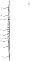
- Fig. 1 shows a schematic representation of a boom 1 for an agricultural sprayer in an extended orientation which may also be referred to extended arrangement or extended position.
- the boom 1 may be applied to an agricultural sprayer which in turn may be provided or received on an implement to be carried or trailed by a tractor or a self-driving agricultural machine.
- the agricultural machine is provided with a tank or reservoir containing a product to be dispensed by spraying to the field.
- the tank will be in fluid communication with sprayer elements (not shown) provided on the boom 1 such as a nozzle system for dispensing the liquid material.
- Fig. 1 show a rear view of the boom 1.
- the boom 1 comprises a plurality of boom sections 2, 3, 4 on one boom side 1a. According to the embodiment shown, there is a plurality of further boom sections on the other boom side 1b.
- the boom section 2 is connected to a middle (boom) section 1c.
- Such boom section may provide for two of the boom section 1c, 2, 3, and 4 in Fig. 1 .
- such arrangement may be provided, with respect to the middle boom section 1c, in a distant location 5 and / or a proximal location 6.
- the middle boom section 1c may be connected to a proximal boom section
- the first and second boom sections 20, 21 are connected by an articulating joint 22 provided in a corner section 23 of the first boom 20 and a corner section 24 of the second boom section 21, the first and second corner sections 23, 24 being provided adjacent to each other.
- the articulating joint 22 allows for a 180 degrees rotational movement between the first and second boom sections 20, 21 as shown in Fig. 2 to 4 .
- the arrangement with the first and second boom sections 20, 21 can be relocated between an extended boom section arrangement (orientation) shown in the top part of the Fig. 2 to 4 and a retracted boom section arrangement (orientation) shown in bottom part of the Fig. 2 to 4 .
- Such relocation may also be referred to as movement between a linear boom section orientation (top) and a parallel boom section orientation (bottom).
- the arrangement comprising the first and second boom sections 20, 21 is assigned an actuator 25 which is attached at least in a mounting or attachment point 25a and providing a driving force for the 180 degrees rotational movement or pivoting between the first and second boom sections 20, 21.
- the actuator 25 is provided with a cylinder-piston arrangement 26 having, for example, a hydraulic cylinder.
- an electric or a magnetic actuator may be provided.
- Embodiments may include a using a pneumatic cylinder as an actuator, or a differential cylinder, a synchronous cylinder, a tandem cylinder, a telescopic cylinder or a combination thereof.
- a moving actuator element 27 can be moved between a retracted position (top) and an extended position (bottom). Movement of the movable actuator element 27 is applied to relocate the arrangement comprising the first and second boom sections 20, 21 between the extended and the retracted position.
- the movable actuator element 27 is functionally connected to an arrangement of hinged elements 28 connecting to both the first and the second boom sections 20, 21.
- Folding or link arm elements 29a, 29b are connected by an articulating joint 30.
- the link arm elements 29a, 29b are provided in a serial arrangement.
- a hinged element 31 provided with a lever element.
- the hinged element 31 is connected to the articulating joint 30 of the folding arm 29 and a first mounting (supporting or attachment) point 32a on the first boom section 20.
- the hinged (lever) element 31 is rotatable or pivotally received on both ends.
- the folding arm 29 is connected to a second mounting (supporting or attachment) point 32b on the second boom section 21.
- At least the first boom section 20 is having a first frame structure 20a provided by frame elements being connected fixedly or detachably.
- the actuator 25 is provided inside the first frame structure 20a of the first boom section 20, for example in a mounting space 34 provided inside or within the first frame structure 20a of the first boom section 20.
- the second boom section 21 is be provided with a second frame structure 21a comprising frame elements connected fixedly or detachably.
- the attachment or mounting point 32 may be provided on the second frame structure 21a.
- the actuator 25 is prevented from rotation while the movable actuator element 27 is moved between the extended and retracted positions by a limiting or anti-rotation device 35.
- the limiting device 35 comprises a guiding mechanism 36 provided with guiding wall elements 36a, 36b receiving the movable actuator element 27 for guiding while the movable or moving actuator element 27 is moved between the extended and retracted positions, thereby, preventing the actuator 25 from rotation.
- the limiting device 35 comprises one or more stop members 37 for preventing rotational movement of the actuator 25 in the process of moving the movable actuator element 27 between the extended and the retracted positions.
- the one or more stop members 37 acting against the actuator 25 are provided with limitation points or projections.
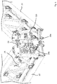
- Fig. 4 to 7 show an embodiment for an arrangement schematically shown in Fig. 2 .
- Fig. 4 to 7 for the same features identical reference numerals are applied like in Fig. 2 .
- Fig. 4 shows the arrangement having the first and second boom sections 20, 21 in the (fully) extended position.
- Fig. 5 and 6 the first and second boom sections 20, 21 are in an intermediate position (partially extended, partially retracted).
- Fig. 7 shows a (fully) retracted position for the first and second boom sections 20, 21.
- the articulating joint 22 is provided in an upper and a lower part of the first and second boom sections 20, 21.
- the actuator 25 is located inside the first frame structure 20a of the first boom section 20.
- the actuator is completely received inside a space spanned the first frame structure 20a.
- the second boom section 21 is provided with the second frame structure 21a receiving inside the second mounting (supporting or attachment) point 32b.
- the stop member 37 abuts against the actuator 25 for preventing the actuator 25 from rotation.
- the movable actuator element 27 is guided by the guiding wall elements 36a, 36b above and underneath the movable actuator element 27 which may be sliding on the guiding wall elements 36a, 36b while moving between the retracted and the extended position.
- the guiding wall elements 36a, 36b are fixed on a frame which prevents the actuator element 27 (and the actuator 25) from rotation (see Fig. 2 ).
Landscapes
- Life Sciences & Earth Sciences (AREA)
- Engineering & Computer Science (AREA)
- Insects & Arthropods (AREA)
- Pest Control & Pesticides (AREA)
- Wood Science & Technology (AREA)
- Zoology (AREA)
- Environmental Sciences (AREA)
- Catching Or Destruction (AREA)
Priority Applications (2)
| Application Number | Priority Date | Filing Date | Title |
|---|---|---|---|
| EP19180646.2A EP3753404B1 (de) | 2019-06-17 | 2019-06-17 | Anordnung für einen aus- und einziehbaren ausleger einer landwirtschaftlichen maschine und landwirtschaftliche spritze |
| PCT/EP2020/065860 WO2020254136A1 (en) | 2019-06-17 | 2020-06-08 | An assembly for an extendable and retractable boom of an agricultural machine and agricultural sprayer |
Applications Claiming Priority (1)
| Application Number | Priority Date | Filing Date | Title |
|---|---|---|---|
| EP19180646.2A EP3753404B1 (de) | 2019-06-17 | 2019-06-17 | Anordnung für einen aus- und einziehbaren ausleger einer landwirtschaftlichen maschine und landwirtschaftliche spritze |
Publications (3)
| Publication Number | Publication Date |
|---|---|
| EP3753404A1 true EP3753404A1 (de) | 2020-12-23 |
| EP3753404B1 EP3753404B1 (de) | 2023-06-07 |
| EP3753404C0 EP3753404C0 (de) | 2023-06-07 |
Family
ID=66912752
Family Applications (1)
| Application Number | Title | Priority Date | Filing Date |
|---|---|---|---|
| EP19180646.2A Active EP3753404B1 (de) | 2019-06-17 | 2019-06-17 | Anordnung für einen aus- und einziehbaren ausleger einer landwirtschaftlichen maschine und landwirtschaftliche spritze |
Country Status (2)
| Country | Link |
|---|---|
| EP (1) | EP3753404B1 (de) |
| WO (1) | WO2020254136A1 (de) |
Families Citing this family (1)
| Publication number | Priority date | Publication date | Assignee | Title |
|---|---|---|---|---|
| US12317887B2 (en) | 2022-08-23 | 2025-06-03 | Deere & Company | System for adjusting boom hinge rake angle of an agricultural sprayer and method thereof |
Citations (7)
| Publication number | Priority date | Publication date | Assignee | Title |
|---|---|---|---|---|
| US4709857A (en) * | 1986-11-20 | 1987-12-01 | Wilger Wilfed H | Variable height field sprayer frame |
| US6719213B1 (en) * | 2002-01-11 | 2004-04-13 | Edward P. Ferguson | Spray boom |
| US20140366460A1 (en) * | 2013-06-12 | 2014-12-18 | Speciality Enterprises, LLC | Agricultural spray boom |
| WO2015082121A1 (en) | 2013-12-05 | 2015-06-11 | Agco Netherlands Bv | Agricultural sprayer with multi-section foldable boom |
| US20160038961A1 (en) * | 2014-08-11 | 2016-02-11 | Deere & Company | Folding lightweight sprayer boom system |
| US20180184638A1 (en) * | 2016-12-31 | 2018-07-05 | Prime Seasons, Inc. | Sprayer boom assembly for a mobile landscape sprayer |
| US20190129375A1 (en) * | 2017-10-27 | 2019-05-02 | CNH Industrial Canada, LTD | System and method for controlling the actuation of wing sections of an implement during an unfolding operation |
Family Cites Families (1)
| Publication number | Priority date | Publication date | Assignee | Title |
|---|---|---|---|---|
| US5988528A (en) * | 1996-12-30 | 1999-11-23 | Case Corporation | Self-centering boom |
-
2019
- 2019-06-17 EP EP19180646.2A patent/EP3753404B1/de active Active
-
2020
- 2020-06-08 WO PCT/EP2020/065860 patent/WO2020254136A1/en not_active Ceased
Patent Citations (7)
| Publication number | Priority date | Publication date | Assignee | Title |
|---|---|---|---|---|
| US4709857A (en) * | 1986-11-20 | 1987-12-01 | Wilger Wilfed H | Variable height field sprayer frame |
| US6719213B1 (en) * | 2002-01-11 | 2004-04-13 | Edward P. Ferguson | Spray boom |
| US20140366460A1 (en) * | 2013-06-12 | 2014-12-18 | Speciality Enterprises, LLC | Agricultural spray boom |
| WO2015082121A1 (en) | 2013-12-05 | 2015-06-11 | Agco Netherlands Bv | Agricultural sprayer with multi-section foldable boom |
| US20160038961A1 (en) * | 2014-08-11 | 2016-02-11 | Deere & Company | Folding lightweight sprayer boom system |
| US20180184638A1 (en) * | 2016-12-31 | 2018-07-05 | Prime Seasons, Inc. | Sprayer boom assembly for a mobile landscape sprayer |
| US20190129375A1 (en) * | 2017-10-27 | 2019-05-02 | CNH Industrial Canada, LTD | System and method for controlling the actuation of wing sections of an implement during an unfolding operation |
Also Published As
| Publication number | Publication date |
|---|---|
| WO2020254136A1 (en) | 2020-12-24 |
| EP3753404B1 (de) | 2023-06-07 |
| EP3753404C0 (de) | 2023-06-07 |
Similar Documents
| Publication | Publication Date | Title |
|---|---|---|
| EP1299598B1 (de) | Stützausleger für fahrbare arbeitsmaschinen und autobetonpumpe mit solchen stützauslegern | |
| US9462799B2 (en) | Pivot hinge boom spray system | |
| CA2970217C (en) | Implement with foldable toolbar system | |
| EP2306804B1 (de) | Einstellbarer und klappbarer v-förmiger Heurechen | |
| EP2729645B1 (de) | Verteilermast für betonpumpen | |
| US8827180B2 (en) | Agricultural sprayer boom having aligned mast and center section | |
| CN106028805B (zh) | 喷洒装置和喷杆减振装置 | |
| EP0847348B1 (de) | Fahrbare arbeitsmaschine mit seitlich ausschwenkbaren stützauslegern | |
| AU771814B2 (en) | Boom sprayer and method of spraying | |
| EP3056083A1 (de) | Landwirtschaftliche feldspritze | |
| US4138063A (en) | Hydraulically-operated fertilizer and chemical-spreading boom | |
| US7152811B2 (en) | Hydraulic boom stabilization device | |
| EP3753404B1 (de) | Anordnung für einen aus- und einziehbaren ausleger einer landwirtschaftlichen maschine und landwirtschaftliche spritze | |
| DE102011078780A1 (de) | Verteilermast für Betonpumpen | |
| EP3753405B1 (de) | Anordnung für einen aus- und einziehbaren ausleger einer landwirtschaftlichen maschine und landwirtschaftliche spritze | |
| US20120112021A1 (en) | Agricultural machine linkage arrangement | |
| RU2813351C2 (ru) | Узел для удлиняемой и складываемой штанги сельскохозяйственной машины и сельскохозяйственного опрыскивателя | |
| US10757853B2 (en) | Folding injector boom for liquid manure spreader | |
| EP2526758B1 (de) | Mähmaschine | |
| AU2020289713B2 (en) | Operating machine with improved stabilisers | |
| US20200390080A1 (en) | Inverted Truss Geometry For Agricultural Spray Boom | |
| CN211298197U (zh) | 一种打药机 | |
| EP3892095B1 (de) | Auslegeranordnung für eine landwirtschaftliche spritze, landwirtschaftliche spritze und verfahren zum betrieb einer landwirtschaftlichen spritze | |
| DE102014110740B4 (de) | Landwirtschaftliches Arbeitsgerät | |
| DE102018116014A1 (de) | Landwirtschaftliches Arbeitsgerät |
Legal Events
| Date | Code | Title | Description |
|---|---|---|---|
| PUAI | Public reference made under article 153(3) epc to a published international application that has entered the european phase |
Free format text: ORIGINAL CODE: 0009012 |
|
| STAA | Information on the status of an ep patent application or granted ep patent |
Free format text: STATUS: REQUEST FOR EXAMINATION WAS MADE |
|
| 17P | Request for examination filed |
Effective date: 20200424 |
|
| AK | Designated contracting states |
Kind code of ref document: A1 Designated state(s): AL AT BE BG CH CY CZ DE DK EE ES FI FR GB GR HR HU IE IS IT LI LT LU LV MC MK MT NL NO PL PT RO RS SE SI SK SM TR |
|
| AX | Request for extension of the european patent |
Extension state: BA ME |
|
| STAA | Information on the status of an ep patent application or granted ep patent |
Free format text: STATUS: EXAMINATION IS IN PROGRESS |
|
| 17Q | First examination report despatched |
Effective date: 20210415 |
|
| GRAP | Despatch of communication of intention to grant a patent |
Free format text: ORIGINAL CODE: EPIDOSNIGR1 |
|
| STAA | Information on the status of an ep patent application or granted ep patent |
Free format text: STATUS: GRANT OF PATENT IS INTENDED |
|
| INTG | Intention to grant announced |
Effective date: 20221130 |
|
| GRAS | Grant fee paid |
Free format text: ORIGINAL CODE: EPIDOSNIGR3 |
|
| GRAA | (expected) grant |
Free format text: ORIGINAL CODE: 0009210 |
|
| STAA | Information on the status of an ep patent application or granted ep patent |
Free format text: STATUS: THE PATENT HAS BEEN GRANTED |
|
| AK | Designated contracting states |
Kind code of ref document: B1 Designated state(s): AL AT BE BG CH CY CZ DE DK EE ES FI FR GB GR HR HU IE IS IT LI LT LU LV MC MK MT NL NO PL PT RO RS SE SI SK SM TR |
|
| REG | Reference to a national code |
Ref country code: GB Ref legal event code: FG4D |
|
| REG | Reference to a national code |
Ref country code: CH Ref legal event code: EP Ref country code: AT Ref legal event code: REF Ref document number: 1571902 Country of ref document: AT Kind code of ref document: T Effective date: 20230615 Ref country code: DE Ref legal event code: R096 Ref document number: 602019029781 Country of ref document: DE |
|
| P01 | Opt-out of the competence of the unified patent court (upc) registered |
Effective date: 20230525 |
|
| U01 | Request for unitary effect filed |
Effective date: 20230630 |
|
| U07 | Unitary effect registered |
Designated state(s): AT BE BG DE DK EE FI FR IT LT LU LV MT NL PT SE SI Effective date: 20230708 |
|
| P04 | Withdrawal of opt-out of the competence of the unified patent court (upc) registered |
Effective date: 20230705 |
|
| REG | Reference to a national code |
Ref country code: LT Ref legal event code: MG9D |
|
| U20 | Renewal fee for the european patent with unitary effect paid |
Year of fee payment: 5 Effective date: 20230914 |
|
| PG25 | Lapsed in a contracting state [announced via postgrant information from national office to epo] |
Ref country code: NO Free format text: LAPSE BECAUSE OF FAILURE TO SUBMIT A TRANSLATION OF THE DESCRIPTION OR TO PAY THE FEE WITHIN THE PRESCRIBED TIME-LIMIT Effective date: 20230907 Ref country code: ES Free format text: LAPSE BECAUSE OF FAILURE TO SUBMIT A TRANSLATION OF THE DESCRIPTION OR TO PAY THE FEE WITHIN THE PRESCRIBED TIME-LIMIT Effective date: 20230607 |
|
| PG25 | Lapsed in a contracting state [announced via postgrant information from national office to epo] |
Ref country code: RS Free format text: LAPSE BECAUSE OF FAILURE TO SUBMIT A TRANSLATION OF THE DESCRIPTION OR TO PAY THE FEE WITHIN THE PRESCRIBED TIME-LIMIT Effective date: 20230607 Ref country code: HR Free format text: LAPSE BECAUSE OF FAILURE TO SUBMIT A TRANSLATION OF THE DESCRIPTION OR TO PAY THE FEE WITHIN THE PRESCRIBED TIME-LIMIT Effective date: 20230607 Ref country code: GR Free format text: LAPSE BECAUSE OF FAILURE TO SUBMIT A TRANSLATION OF THE DESCRIPTION OR TO PAY THE FEE WITHIN THE PRESCRIBED TIME-LIMIT Effective date: 20230908 |
|
| PG25 | Lapsed in a contracting state [announced via postgrant information from national office to epo] |
Ref country code: SK Free format text: LAPSE BECAUSE OF FAILURE TO SUBMIT A TRANSLATION OF THE DESCRIPTION OR TO PAY THE FEE WITHIN THE PRESCRIBED TIME-LIMIT Effective date: 20230607 |
|
| PG25 | Lapsed in a contracting state [announced via postgrant information from national office to epo] |
Ref country code: IS Free format text: LAPSE BECAUSE OF FAILURE TO SUBMIT A TRANSLATION OF THE DESCRIPTION OR TO PAY THE FEE WITHIN THE PRESCRIBED TIME-LIMIT Effective date: 20231007 |
|
| PG25 | Lapsed in a contracting state [announced via postgrant information from national office to epo] |
Ref country code: SM Free format text: LAPSE BECAUSE OF FAILURE TO SUBMIT A TRANSLATION OF THE DESCRIPTION OR TO PAY THE FEE WITHIN THE PRESCRIBED TIME-LIMIT Effective date: 20230607 Ref country code: SK Free format text: LAPSE BECAUSE OF FAILURE TO SUBMIT A TRANSLATION OF THE DESCRIPTION OR TO PAY THE FEE WITHIN THE PRESCRIBED TIME-LIMIT Effective date: 20230607 Ref country code: RO Free format text: LAPSE BECAUSE OF FAILURE TO SUBMIT A TRANSLATION OF THE DESCRIPTION OR TO PAY THE FEE WITHIN THE PRESCRIBED TIME-LIMIT Effective date: 20230607 Ref country code: IS Free format text: LAPSE BECAUSE OF FAILURE TO SUBMIT A TRANSLATION OF THE DESCRIPTION OR TO PAY THE FEE WITHIN THE PRESCRIBED TIME-LIMIT Effective date: 20231007 Ref country code: CZ Free format text: LAPSE BECAUSE OF FAILURE TO SUBMIT A TRANSLATION OF THE DESCRIPTION OR TO PAY THE FEE WITHIN THE PRESCRIBED TIME-LIMIT Effective date: 20230607 |
|
| REG | Reference to a national code |
Ref country code: CH Ref legal event code: PL |
|
| PG25 | Lapsed in a contracting state [announced via postgrant information from national office to epo] |
Ref country code: PL Free format text: LAPSE BECAUSE OF FAILURE TO SUBMIT A TRANSLATION OF THE DESCRIPTION OR TO PAY THE FEE WITHIN THE PRESCRIBED TIME-LIMIT Effective date: 20230607 |
|
| REG | Reference to a national code |
Ref country code: DE Ref legal event code: R097 Ref document number: 602019029781 Country of ref document: DE |
|
| PG25 | Lapsed in a contracting state [announced via postgrant information from national office to epo] |
Ref country code: MC Free format text: LAPSE BECAUSE OF FAILURE TO SUBMIT A TRANSLATION OF THE DESCRIPTION OR TO PAY THE FEE WITHIN THE PRESCRIBED TIME-LIMIT Effective date: 20230607 |
|
| REG | Reference to a national code |
Ref country code: IE Ref legal event code: MM4A |
|
| PG25 | Lapsed in a contracting state [announced via postgrant information from national office to epo] |
Ref country code: MC Free format text: LAPSE BECAUSE OF FAILURE TO SUBMIT A TRANSLATION OF THE DESCRIPTION OR TO PAY THE FEE WITHIN THE PRESCRIBED TIME-LIMIT Effective date: 20230607 |
|
| PLBE | No opposition filed within time limit |
Free format text: ORIGINAL CODE: 0009261 |
|
| STAA | Information on the status of an ep patent application or granted ep patent |
Free format text: STATUS: NO OPPOSITION FILED WITHIN TIME LIMIT |
|
| PG25 | Lapsed in a contracting state [announced via postgrant information from national office to epo] |
Ref country code: IE Free format text: LAPSE BECAUSE OF NON-PAYMENT OF DUE FEES Effective date: 20230617 |
|
| PG25 | Lapsed in a contracting state [announced via postgrant information from national office to epo] |
Ref country code: IE Free format text: LAPSE BECAUSE OF NON-PAYMENT OF DUE FEES Effective date: 20230617 Ref country code: CH Free format text: LAPSE BECAUSE OF NON-PAYMENT OF DUE FEES Effective date: 20230630 |
|
| 26N | No opposition filed |
Effective date: 20240308 |
|
| U20 | Renewal fee for the european patent with unitary effect paid |
Year of fee payment: 6 Effective date: 20240625 |
|
| P05 | Withdrawal of opt-out of the competence of the unified patent court (upc) changed |
Free format text: CASE NUMBER: APP_545621/2023 Effective date: 20230708 |
|
| PGFP | Annual fee paid to national office [announced via postgrant information from national office to epo] |
Ref country code: GB Payment date: 20250618 Year of fee payment: 7 |
|
| PG25 | Lapsed in a contracting state [announced via postgrant information from national office to epo] |
Ref country code: CY Free format text: LAPSE BECAUSE OF FAILURE TO SUBMIT A TRANSLATION OF THE DESCRIPTION OR TO PAY THE FEE WITHIN THE PRESCRIBED TIME-LIMIT; INVALID AB INITIO Effective date: 20190617 |
|
| U20 | Renewal fee for the european patent with unitary effect paid |
Year of fee payment: 7 Effective date: 20250627 |
|
| PG25 | Lapsed in a contracting state [announced via postgrant information from national office to epo] |
Ref country code: HU Free format text: LAPSE BECAUSE OF FAILURE TO SUBMIT A TRANSLATION OF THE DESCRIPTION OR TO PAY THE FEE WITHIN THE PRESCRIBED TIME-LIMIT; INVALID AB INITIO Effective date: 20190617 |
|
| PG25 | Lapsed in a contracting state [announced via postgrant information from national office to epo] |
Ref country code: TR Free format text: LAPSE BECAUSE OF FAILURE TO SUBMIT A TRANSLATION OF THE DESCRIPTION OR TO PAY THE FEE WITHIN THE PRESCRIBED TIME-LIMIT Effective date: 20230607 |