EP3753216B1 - Techniques for wireless communications using multiple cyclic prefix types - Google Patents
Techniques for wireless communications using multiple cyclic prefix types Download PDFInfo
- Publication number
- EP3753216B1 EP3753216B1 EP19708710.9A EP19708710A EP3753216B1 EP 3753216 B1 EP3753216 B1 EP 3753216B1 EP 19708710 A EP19708710 A EP 19708710A EP 3753216 B1 EP3753216 B1 EP 3753216B1
- Authority
- EP
- European Patent Office
- Prior art keywords
- slot
- slot format
- symbol
- type
- symbols
- Prior art date
- Legal status (The legal status is an assumption and is not a legal conclusion. Google has not performed a legal analysis and makes no representation as to the accuracy of the status listed.)
- Active
Links
Images


Classifications
-
- H—ELECTRICITY
- H04—ELECTRIC COMMUNICATION TECHNIQUE
- H04L—TRANSMISSION OF DIGITAL INFORMATION, e.g. TELEGRAPHIC COMMUNICATION
- H04L5/00—Arrangements affording multiple use of the transmission path
- H04L5/14—Two-way operation using the same type of signal, i.e. duplex
- H04L5/1469—Two-way operation using the same type of signal, i.e. duplex using time-sharing
-
- H—ELECTRICITY
- H04—ELECTRIC COMMUNICATION TECHNIQUE
- H04L—TRANSMISSION OF DIGITAL INFORMATION, e.g. TELEGRAPHIC COMMUNICATION
- H04L27/00—Modulated-carrier systems
- H04L27/26—Systems using multi-frequency codes
- H04L27/2601—Multicarrier modulation systems
- H04L27/2602—Signal structure
-
- H—ELECTRICITY
- H04—ELECTRIC COMMUNICATION TECHNIQUE
- H04L—TRANSMISSION OF DIGITAL INFORMATION, e.g. TELEGRAPHIC COMMUNICATION
- H04L27/00—Modulated-carrier systems
- H04L27/26—Systems using multi-frequency codes
- H04L27/2601—Multicarrier modulation systems
- H04L27/2602—Signal structure
- H04L27/26025—Numerology, i.e. varying one or more of symbol duration, subcarrier spacing, Fourier transform size, sampling rate or down-clocking
-
- H—ELECTRICITY
- H04—ELECTRIC COMMUNICATION TECHNIQUE
- H04L—TRANSMISSION OF DIGITAL INFORMATION, e.g. TELEGRAPHIC COMMUNICATION
- H04L27/00—Modulated-carrier systems
- H04L27/26—Systems using multi-frequency codes
- H04L27/2601—Multicarrier modulation systems
- H04L27/2602—Signal structure
- H04L27/2605—Symbol extensions, e.g. Zero Tail, Unique Word [UW]
- H04L27/2607—Cyclic extensions
-
- H—ELECTRICITY
- H04—ELECTRIC COMMUNICATION TECHNIQUE
- H04L—TRANSMISSION OF DIGITAL INFORMATION, e.g. TELEGRAPHIC COMMUNICATION
- H04L5/00—Arrangements affording multiple use of the transmission path
- H04L5/0001—Arrangements for dividing the transmission path
- H04L5/0003—Two-dimensional division
- H04L5/0005—Time-frequency
- H04L5/0007—Time-frequency the frequencies being orthogonal, e.g. OFDM(A) or DMT
-
- H—ELECTRICITY
- H04—ELECTRIC COMMUNICATION TECHNIQUE
- H04W—WIRELESS COMMUNICATION NETWORKS
- H04W72/00—Local resource management
- H04W72/04—Wireless resource allocation
- H04W72/044—Wireless resource allocation based on the type of the allocated resource
- H04W72/0446—Resources in time domain, e.g. slots or frames
-
- H—ELECTRICITY
- H04—ELECTRIC COMMUNICATION TECHNIQUE
- H04W—WIRELESS COMMUNICATION NETWORKS
- H04W72/00—Local resource management
- H04W72/20—Control channels or signalling for resource management
- H04W72/23—Control channels or signalling for resource management in the downlink direction of a wireless link, i.e. towards a terminal
- H04W72/231—Control channels or signalling for resource management in the downlink direction of a wireless link, i.e. towards a terminal the control data signalling from the layers above the physical layer, e.g. RRC or MAC-CE signalling
Definitions
- aspects of the present disclosure relate generally to wireless communication systems, and more particularly, to the use of cyclic prefix (CP) in wireless communications.
- CP cyclic prefix
- Wireless communication systems are widely deployed to provide various types of communication content such as voice, video, packet data, messaging, broadcast, and so on.
- These systems may be multiple-access systems capable of supporting communication with multiple users by sharing the available system resources (e.g., time, frequency, and power).
- Examples of such multiple-access systems include code-division multiple access (CDMA) systems, time-division multiple access (TDMA) systems, frequency-division multiple access (FDMA) systems, and orthogonal frequency-division multiple access (OFDMA) systems, and single-carrier frequency division multiple access (SC-FDMA) systems.
- CDMA code-division multiple access
- TDMA time-division multiple access
- FDMA frequency-division multiple access
- OFDMA orthogonal frequency-division multiple access
- SC-FDMA single-carrier frequency division multiple access
- WO 2017/195584 A1 relates to the usage of dynamic cyclic prefix (CP) lengths in wireless communications.
- the UE may determine a first CP length for a first symbol of a plurality of symbols and determine a second CP length, different from the first CP length, for a second symbol of the plurality of symbols.
- the symbols may be in the same TTI or different TTIs.
- US 2015/256308 A1 relates to techniques for providing flexible sub-carrier spacing and symbol duration allocation according to different multiple access block (MAB) types.
- a plurality of MAB types are defined having frequency-time slots with at least one of the MAB types having at least one of a different sub-carrier spacing, a different useful symbol length and a different cyclic prefix length.
- US 2010/074244 A1 relates to a UE forming a first symbol sequence comprising a first cyclic prefix, a first useful portion, and a first cyclic postfix for the reference signal. Also, the UE forms a second symbol sequence comprising a second cyclic prefix, a second useful portion, and a second cyclic postfix for the data.
- the first and second cyclic prefixes may have a first length of P 1 .
- WO 2016/119890 A1 discloses further forms of data signals that may be sent in a first and second type of data access.
- a first specified number of OFDM samples is equal to the second specified number of OFDM samples, and so the length D 7 is equal to the length D 6 , while the total length of the first signal, that is, (D 7 + L 7 + S 7 ), is equal to the length of one of the time slots, and the total length of the second signal, that is, (O 6 + L 6 ), is also equal to the length of one of the time slots.
- LG ELECTRONICS “Multiplexing NCP and ECP", 3GPP DRAFT; R1-1710358 NUMEROLOGY, 3RD GENERATION PARTNERSHIP PROJECT (3GPP), MOBILE COMPETENCE CENTRE ; 650, ROUTE DES LUCIOLES ; F-06921 SOPHIA-ANTIPOLIS CEDEX ; FRANCE,vol. RAN WG1, no. Qingdao, P.R. China; 26 June 2017 , discloses multiplexing of NCP and ECP symbols within a slot, wherein ECP UL symbols are aligned either at the end of the slot or with regard to NCP DL symbols.
- 5G communications technology can include: enhanced mobile broadband addressing human-centric use cases for access to multimedia content, services and data; ultra-reliable-low latency communications (URLLC) with certain specifications for latency and reliability; and massive machine type communications, which can allow a very large number of connected devices and transmission of a relatively low volume of non-delay-sensitive information.
- URLLC ultra-reliable-low latency communications
- massive machine type communications which can allow a very large number of connected devices and transmission of a relatively low volume of non-delay-sensitive information.
- nodes in a wireless network can be configured with different CP types for different links, different signals transmitted over the different links, etc.
- a node can be configured to communicate (e.g., transmit or receive) signals with one or more other nodes using a different CP type for each of at least two signals, where using the different CP type may result in a different timeline for the communications as well.
- a base station can transmit one or more broadcast signals using a normal CP and can multiplex, with the one or more broadcast signals, one or more unicast signals that use an extended CP.
- a user equipment (UE) or other node can receive the one or more broadcast signals and/or unicast signals, which can be multiplexed (e.g., in a given slot), and may each use a different CP type.
- a slot format configuration for the normal CP and extended CP communications can be coordinated to provide a desirable level of compatibility to minimize conflicting communication directions (e.g., uplink vs. downlink) between symbols in the slot.
- NR UEs can be semi-statically configured with a specific numerology (e.g., numerology can refer to a CP overhead and/or subcarrier spacing (SCS)), where NR can support extended CP at least for 60 kilohertz (kHz) SCS.
- numerology can refer to a CP overhead and/or subcarrier spacing (SCS)
- SCCS subcarrier spacing
- one slot can include 12 orthogonal frequency division multiplexing (OFDM) symbols.
- OFDM orthogonal frequency division multiplexing
- NR can also support normal CP where one slot can include 14 OFDM symbols.
- uplink and downlink can be configured with different CP types (e.g., normal or extended CP). Additional configurations for using CP may be desired.
- slot format configuration for wireless networks can be semi-static and group-specific.
- Each slot can include a plurality of symbols, where each symbol can be configured for either downlink, uplink, or flexible communications.
- the slots configured for flexible communications can be dynamically reconfigured as downlink or uplink in a dynamic and/or UE-specific manner (e.g., by using group common physical downlink control channel (GC-PDCCH) to dynamically configure the flexible symbols).
- GC-PDCCH group common physical downlink control channel
- CP type or length (e.g., normal CP, extended CP, etc.) configuration can be semi-static and UE-specific, and different CP types can be associated with different timelines (e.g., a different number of symbols in a similar length slot, where a timeline can correspond to the number of symbols in a slot, a corresponding duration for the symbols or slot, etc.).
- some signals such as primary synchronization signal (PSS), secondary synchronization signal (SSS), multicast physical downlink shared channel (PDSCH), etc., may be configured to use normal CP while other unicast transmissions maybe configured with extended CP in the same slot. This can result in multiplexing of normal CP and extended CP communications in the same slot.
- Normal CP slot formats can be based on using a first number of OFDM symbols (e.g., 14) per slot, whereas extended CP slot formats can be based on using a second number of OFDM symbols (e.g., 12) per slot, which can result in different communication timelines per slot.
- a first number of OFDM symbols e.g. 14
- extended CP slot formats can be based on using a second number of OFDM symbols (e.g., 12) per slot, which can result in different communication timelines per slot.
- aspects described herein relate to multiplexing normal CP and extended CP communications, which may include adapting a slot format to use with one CP type based on the slot format defined for another CP type, where the slot formats may be based on different timelines. Adapting the slot format using concepts described herein can lessen or minimize conflict in transmission direction between symbols of the slot formats that occur at the same or similar times.
- network nodes can derive the slot format for one CP type based on the slot format for another CP type and/or based on associated timelines of the CP types.
- a network node e.g., the base station
- can configure another network node e.g., the UE
- the slot formats to use for each CP type (e.g., by specifying an indicator representing the slot format, such as a slot format indicator (SFI) in the configuration), where the slot formats may exhibit some level of compatibility between the types of configured symbols in the slot.
- the network nodes can be accordingly configured to communicate multiplexed signals that are based on different CP types and/or associated with different corresponding timelines while decreasing conflict in communication direction between symbols on the multiple timelines.
- a component may be, but is not limited to being, a process running on a processor, a processor, an object, an executable, a thread of execution, a program, and/or a computer.
- an application running on a computing device and the computing device can be a component.
- One or more components can reside within a process and/or thread of execution and a component can be localized on one computer and/or distributed between two or more computers.
- these components can execute from various computer readable media having various data structures stored thereon.
- the components can communicate by way of local and/or remote processes such as in accordance with a signal having one or more data packets, such as data from one component interacting with another component in a local system, distributed system, and/or across a network such as the Internet with other systems by way of the signal.
- a CDMA system may implement a radio technology such as CDMA2000, Universal Terrestrial Radio Access (UTRA), etc.
- CDMA2000 covers IS-2000, IS-95, and IS-856 standards.
- IS-2000 Releases 0 and A are commonly referred to as CDMA2000 1X, 1X, etc.
- IS-856 (TIA-856) is commonly referred to as CDMA2000 1xEV-DO, High Rate Packet Data (HRPD), etc.
- UTRA includes Wideband CDMA (WCDMA) and other variants of CDMA.
- a TDMA system may implement a radio technology such as Global System for Mobile Communications (GSM).
- GSM Global System for Mobile Communications
- An OFDMA system may implement a radio technology such as Ultra Mobile Broadband (UMB), Evolved UTRA (E-UTRA), IEEE 802.11 (Wi-Fi), IEEE 802.16 (WiMAX), IEEE 802.20, Flash-OFDM TM , etc.
- UMB Ultra Mobile Broadband
- E-UTRA Evolved UTRA
- Wi-Fi Wi-Fi
- WiMAX IEEE 802.16
- IEEE 802.20 Flash-OFDM TM
- UMB Ultra Mobile Broadband
- E-UTRA Evolved UTRA
- Wi-Fi Wi-Fi
- WiMAX IEEE 802.16
- IEEE 802.20 Flash-OFDM TM
- UTRA and E-UTRA are part of Universal Mobile Telecommunication System (UMTS).
- 3GPP Long Term Evolution (LTE) and LTE-Advanced (LTE-A) are new releases of
- CDMA2000 and UMB are described in documents from an organization named "3rd Generation Partnership Project 2" (3GPP2).
- 3GPP2 3rd Generation Partnership Project 2
- the techniques described herein may be used for the systems and radio technologies mentioned above as well as other systems and radio technologies, including cellular (e.g., LTE) communications over a shared radio frequency spectrum band.
- LTE Long Term Evolution
- LTE terminology is used in much of the description below, although the techniques are applicable beyond LTE/LTE-A applications (e.g., to 5G networks or other next generation communication systems).
- FIG. 1 illustrates an example of a wireless communication system 100 in accordance with various aspects of the present disclosure.
- the wireless communication system 100 may include one or more base stations 105, one or more UEs 115, and a core network 130.
- the core network 130 may provide user authentication, access authorization, tracking, internet protocol (IP) connectivity, and other access, routing, or mobility functions.
- IP internet protocol
- the base stations 105 may interface with the core network 130 through backhaul links 132 (e.g., S1, etc.).
- the base stations 105 may perform radio configuration and scheduling for communication with the UEs 115, or may operate under the control of a base station controller (not shown).
- the base stations 105 may communicate, either directly or indirectly (e.g., through core network 130), with one another over backhaul links 134 (e.g., X2, etc.), which may be wired or wireless communication links.
- backhaul links 134 e.g., X2, etc.
- the base stations 105 may wirelessly communicate with the UEs 115 via one or more base station antennas. Each of the base stations 105 may provide communication coverage for a respective geographic coverage area 110.
- base stations 105 may be referred to as a network entity, a base transceiver station, a radio base station, an access point, a radio transceiver, a NodeB, eNodeB (eNB), Home NodeB, a Home eNodeB, gNB (e.g., in 5G NR) or some other suitable terminology.
- the geographic coverage area 110 for a base station 105 may be divided into sectors making up only a portion of the coverage area (not shown).
- the wireless communication system 100 may include base stations 105 of different types (e.g., macro or small cell base stations). There may be overlapping geographic coverage areas 110 for different technologies.
- the wireless communication system 100 may be or include a Long Term Evolution (LTE) or LTE-Advanced (LTE-A) network.
- the wireless communication system 100 may also be a next generation network, such as a 5G wireless communication network.
- LTE/LTE-A networks the term evolved node B (eNB) (e.g., or gNB in 5G networks), etc. may be generally used to describe the base stations 105, while the term UE may be generally used to describe the UEs 115.
- the wireless communication system 100 may be a heterogeneous LTE/LTE-A network in which different types of eNBs provide coverage for various geographical regions.
- each eNB or base station 105 may provide communication coverage for a macro cell, a small cell, or other types of cell.
- the term "cell” is a 3GPP term that can be used to describe a base station, a carrier or component carrier associated with a base station, or a coverage area (e.g., sector, etc.) of a carrier or base station, depending on context.
- a macro cell may cover a relatively large geographic area (e.g., several kilometers in radius) and may allow unrestricted access by UEs 115 with service subscriptions with the network provider.
- a small cell may include a lower-powered base station, as compared with a macro cell, that may operate in the same or different (e.g., licensed, unlicensed, etc.) frequency bands as macro cells.
- Small cells may include pico cells, femto cells, and micro cells according to various examples.
- a pico cell for example, may cover a small geographic area and may allow unrestricted access by UEs 115 with service subscriptions with the network provider.
- a femto cell may also cover a small geographic area (e.g., a home) and may provide restricted access by UEs 115 having an association with the femto cell (e.g., UEs 115 in a closed subscriber group (CSG), UEs 115 for users in the home, and the like).
- An eNB for a macro cell may be referred to as a macro eNB, gNB, etc.
- An eNB for a small cell may be referred to as a small cell eNB, a pico eNB, a femto eNB, or a home eNB.
- An eNB may support one or multiple (e.g., two, three, four, and the like) cells (e.g., component carriers).
- the communication networks may be packet-based networks that operate according to a layered protocol stack and data in the user plane may be based on the IP.
- a packet data convergence protocol (PDCP) layer can provide header compression, ciphering, integrity protection, etc. of IP packets.
- a radio link control (RLC) layer may perform packet segmentation and reassembly to communicate over logical channels.
- a media access control (MAC) layer may perform priority handling and multiplexing of logical channels into transport channels.
- the MAC layer may also use HARQ to provide retransmission at the MAC layer to improve link efficiency.
- the radio resource control (RRC) protocol layer may provide establishment, configuration, and maintenance of an RRC connection between a UE 115 and the base stations 105.
- the RRC protocol layer may also be used for core network 130 support of radio bearers for the user plane data.
- the transport channels may be mapped to physical channels.
- the UEs 115 may be dispersed throughout the wireless communication system 100, and each UE 115 may be stationary or mobile.
- a UE 115 may also include or be referred to by those skilled in the art as a mobile station, a subscriber station, a mobile unit, a subscriber unit, a wireless unit, a remote unit, a mobile device, a wireless device, a wireless communications device, a remote device, a mobile subscriber station, an access terminal, a mobile terminal, a wireless terminal, a remote terminal, a handset, a user agent, a mobile client, a client, or some other suitable terminology.
- a UE 115 may be a cellular phone, a personal digital assistant (PDA), a wireless modem, a wireless communication device, a handheld device, a tablet computer, a laptop computer, a cordless phone, a wireless local loop (WLL) station, an entertainment device, a vehicular component, or the like.
- PDA personal digital assistant
- WLL wireless local loop
- a UE may be able to communicate with various types of base stations and network equipment including macro eNBs, small cell eNBs, relay base stations, and the like.
- the communication links 125 shown in wireless communication system 100 may carry UL transmissions from a UE 115 to a base station 105, or downlink (DL) transmissions, from a base station 105 to a UE 115.
- the downlink transmissions may also be called forward link transmissions while the uplink transmissions may also be called reverse link transmissions.
- Each communication link 125 may include one or more carriers, where each carrier may be a signal made up of multiple sub-carriers (e.g., waveform signals of different frequencies) modulated according to the various radio technologies described above.
- Each modulated signal may be sent on a different sub-carrier and may carry control information (e.g., reference signals, control channels, etc.), overhead information, user data, etc.
- the communication links 125 may transmit bidirectional communications using frequency division duplex (FDD) (e.g., using paired spectrum resources) or time division duplex (TDD) operation (e.g., using unpaired spectrum resources).
- FDD frequency division duplex
- TDD time division duplex
- Frame structures may be defined for FDD (e.g., frame structure type 1) and TDD (e.g., frame structure type 2).
- base stations 105 or UEs 115 may include multiple antennas for employing antenna diversity schemes to improve communication quality and reliability between base stations 105 and UEs 115. Additionally or alternatively, base stations 105 or UEs 115 may employ multiple input multiple output (MIMO) techniques that may take advantage of multi-path environments to transmit multiple spatial layers carrying the same or different coded data.
- MIMO multiple input multiple output
- Wireless communication system 100 may support operation on multiple cells or carriers, a feature which may be referred to as carrier aggregation (CA) or multi-carrier operation.
- a carrier may also be referred to as a component carrier (CC), a layer, a channel, etc.
- CC component carrier
- the terms “carrier,” “component carrier,” “cell,” and “channel” may be used interchangeably herein.
- a UE 115 may be configured with multiple downlink CCs and one or more uplink CCs for carrier aggregation.
- Carrier aggregation may be used with both FDD and TDD component carriers.
- one or more of the base stations 105 may include a multiplexing component 240 for multiplexing communications using different CP types for communication according to different timelines, which may be based on a length associated with the CP type.
- One or more of the UEs 115 may include a communicating component 340 for receiving and decoding multiplexed communications that are based on the different CP types.
- the one or more UEs 115 may additionally or alternatively include a multiplexing component 240 to multiplex communications of different CP types, according to aspects described herein, and/or the one or more base stations 105 may include a communicating component 340 for receiving and decoding the multiplexed communications.
- different UEs 115 may include the multiplexing component 240 and/or communicating component 340 to facilitate UE-to-UE communications, etc.
- FIGS. 2-8 aspects are depicted with reference to one or more components and one or more methods that may perform the actions or operations described herein, where aspects in dashed line may be optional.
- FIGS. 4-5 are presented in a particular order and/or as being performed by an example component, it should be understood that the ordering of the actions and the components performing the actions may be varied, depending on the implementation.
- the following actions, functions, and/or described components may be performed by a specially-programmed processor, a processor executing specially-programmed software or computer-readable media, or by any other combination of a hardware component and/or a software component capable of performing the described actions or functions.
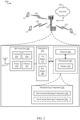
- a block diagram 200 is shown that includes a portion of a wireless communications system having multiple UEs 115 in communication with a base station 105 via communication links 125, where the base station 105 is also connected to a network 210.
- the UEs 115 may be examples of the UEs described in the present disclosure that are configured to receive and decode multiplexed communications of different CP types (e.g., communications that may overlap in a time domain).
- the base station 105 may be an example of the base stations described in the present disclosure (e.g., eNB, gNB, other types of access points, etc. providing one or more macrocells, small cells, etc.) that are configured to multiplex and transmit communications that use different CP types that may correspond to different communication timelines.
- the base station in FIG. 2 may include one or more processors 205 and/or memory 202 that may operate in combination with a multiplexing component 240 to perform the functions, methods (e.g., method 400 of FIG. 4 ), etc. presented in the present disclosure.
- the multiplexing component 240 may include one or more components for multiplexing communications having different CP types (and thus perhaps different communication timelines).
- multiplexing component 240 may include a slot format indicating component 242 for indicating a slot format associated with a first CP type, and/or a slot format deriving component 244 for deriving or interpolating (and/or additionally indicating) a second slot format associated with a second CP type.
- the one or more processors 205 may include a modem 220 that uses one or more modem processors.
- the various functions related to the multiplexing component 240, and/or its sub-components, may be included in modem 220 and/or processor 205 and, in an aspect, can be executed by a single processor, while in other aspects, different ones of the functions may be executed by a combination of two or more different processors.
- the one or more processors 205 may include any one or any combination of a modem processor, or a baseband processor, or a digital signal processor, or a transmit processor, or a transceiver processor associated with transceiver 270, or a system-on-chip (SoC).
- SoC system-on-chip
- multiplexing component 240 may operate at one or more communication layers, such as a physical layer (e.g., layer 1 (L1)), media access control (MAC) layer (e.g., layer 2 (L2)), PDCP layer or RLC layer (e.g., layer 3 (L3)), etc., to multiplex communications and/or transmit an indication of a slot format for one or more CP types, etc.
- L1 physical layer
- MAC media access control
- L2 layer 2
- RLC layer e.g., layer 3 (L3)
- the multiplexing component 240 and each of the sub-components may comprise hardware, firmware, and/or software and may be configured to execute code or perform instructions stored in a memory (e.g., a computer-readable storage medium, such as memory 202 discussed below).
- the base station 105 in FIG. 2 may include a radio frequency (RF) front end 290 and transceiver 270 for receiving and transmitting radio transmissions to, for example, UEs 115.
- the transceiver 270 may coordinate with the modem 220 to receive signals for, or transmit signals generated by, the multiplexing component 240 to the UEs.
- RF radio frequency
- RF front end 290 may be connected to one or more antennas 273 and can include one or more switches 292, one or more amplifiers (e.g., power amplifiers (PAs) 294 and/or low-noise amplifiers 291), and one or more filters 293 for transmitting and receiving RF signals on uplink channels and downlink channels, transmitting and receiving signals, etc.
- the components of the RF front end 290 can connect with transceiver 270.
- the transceiver 270 may connect to one or more of modem 220 and processors 205.
- the transceiver 270 may be configured to transmit (e.g., via transmitter (TX) radio 275) and receive (e.g., via receiver (RX) radio 280) wireless signals through antennas 273 via the RF front end 290.
- the transceiver 270 may be tuned to operate at specified frequencies such that the base station 105 can communicate with, for example, UEs 115.
- the modem 220 can configure the transceiver 270 to operate at a specified frequency and power level based on the configuration of the base station 105 and communication protocol used by the modem 220.
- the base station 105 in FIG. 2 may further include a memory 202, such as for storing data used herein and/or local versions of applications or multiplexing component 240 and/or one or more of its sub-components being executed by processor 205.
- Memory 202 can include any type of computer-readable medium usable by a computer or processor 205, such as random access memory (RAM), read only memory (ROM), tapes, magnetic discs, optical discs, volatile memory, non-volatile memory, and any combination thereof.
- RAM random access memory
- ROM read only memory
- tapes such as magnetic discs, optical discs, volatile memory, non-volatile memory, and any combination thereof.
- memory 202 may be a computer-readable storage medium that stores one or more computer-executable codes defining multiplexing component 240 and/or one or more of its sub-components.
- the one or more processors 305 may include a modem 320 that uses one or more modem processors.
- the various functions related to the communicating component 340, and/or its sub-components, may be included in modem 320 and/or processor 305 and, in an aspect, can be executed by a single processor, while in other aspects, different ones of the functions may be executed by a combination of two or more different processors.
- the one or more processors 305 may include any one or any combination of a modem processor, or a baseband processor, or a digital signal processor, or a transmit processor, or a transceiver processor associated with transceiver 370, or a system-on-chip (SoC).
- SoC system-on-chip
- the one or more processors 305 may execute functions and components included in the communicating component 340.
- communicating component 340 may operate at one or more communication layers, such as physical layer or L1, MAC layer or L2, a PDCP/RLC layer or L3, etc., to receive communications having different CP types, receive slot format indicators for communications related to the one or more of the different CP types, etc.
- RF front end 390 may be connected to one or more antennas 373 and can include one or more switches 392, one or more amplifiers (e.g., PAs 394 and/or LNAs 391), and one or more filters 393 for transmitting and receiving RF signals on uplink channels and downlink channels.
- the components of the RF front end 390 can connect with transceiver 370.
- the transceiver 370 may connect to one or more of modem 320 and processors 305.
- the transceiver 370 may be configured to transmit (e.g., via transmitter (TX) radio 375) and receive (e.g., via receiver (RX) radio 380) wireless signals through antennas 373 via the RF front end 390.
- the transceiver 370 may be tuned to operate at specified frequencies such that the UE 115 can communicate with, for example, base stations 105.
- the modem 320 can configure the transceiver 370 to operate at a specified frequency and power level based on the configuration of the UE 115 and communication protocol used by the modem 320.
- the UE 115 may include a bus 311 for coupling one or more of the RF front end 390, the transceiver 374, the memory 302, or the processor 305, and to exchange signaling information between each of the components and/or sub-components of the UE 115.
- the processor(s) 305 may correspond to one or more of the processors described in connection with the UE in FIG. 9 .
- the memory 302 may correspond to the memory described in connection with the UE in FIG. 9 .
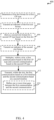
- FIG. 4 illustrates a flow chart of an example of a method 400 for multiplexing (e.g., by a base station) communications having different CP types.
- a UE can also perform the functions described in method 400 and/or include the corresponding components of FIG. 2 to multiplex communications having different CP types.
- a first slot format for a first CP type can be determined.
- slot format indicating component 242 e.g., in conjunction with processor(s) 205, memory 202, transceiver 270, multiplexing component 240, etc., determines a first slot format for a first CP type.
- slot format indicating component 242 can select the first slot format based on one or more parameters related to communicating with a UE 115, such as a signal strength or quality, a load at the base station 105, a buffer status report from the UE 115 indicating an amount of data to transmit, a quality of service (QoS), bit rate, or other performance metric for one or more links or bearers, etc.
- QoS quality of service
- the slot format may correspond to defining a number and/or pattern of symbols in a slot for a communication direction (e.g., downlink, uplink, etc.).
- the slot format also includes one or more flexible symbols that may be dynamically configured for downlink or uplink communications.
- a wireless technology such as 5G NR, may define a number of slot formats that specify a number and/or pattern of downlink, uplink, or flexible symbols in a slot.
- FIG. 6 illustrates an example of slot formats 600, 610 that are defined in 5G NR for normal CP.
- slot format 600 includes three downlink symbols, followed by eight flexible symbols, followed by three uplink symbols, for a total of 14 symbols in the slot.
- slot format 610 includes two downlink symbols, followed by a flexible symbol, followed by four uplink symbols, followed by two downlink symbols, followed by a flexible symbol, followed by three uplink symbols for a total of 14 symbols in the slot.
- slot format indicating component 242 can select the slot format for a first CP type (e.g., normal CP) based on one or more slot formats defined in a wireless communication technology, such as 5G NR.
- a first CP type e.g., normal CP
- an indicator for the first slot format can be transmitted.
- slot format indicating component 242 e.g., in conjunction with processor(s) 205, memory 202, transceiver 270, multiplexing component 240, etc., can transmit the indicator of the first slot format.
- slot format indicating component 242 can transmit the indicator to one or more UEs 115 by using an indicator in a configuration or related signaling, such as in downlink control information (DCI) in a downlink control channel (e.g., PDCCH), etc.
- DCI downlink control information
- PDCCH downlink control channel
- slot format indicating component 242 may determine and/or indicate a communication direction (e.g., downlink or uplink) for the flexible symbols of the slot in a separate configuration.
- slot format indicating component 242 can determine and/or transmit the indicator semi-statically, dynamically, etc., as the selected format may be UE-specific, group-specific, etc.
- slot format indicating component 242 can transmit a slot format or related indicator in a radio resource control (RRC) signal, a dedicated control channel communication, and/or the like.
- RRC radio resource control
- slot format indicating component 242 may indicate an initial slot format and may override the initial slot format with a new slot format in dynamic signaling.
- a second slot format for a second CP type is derived based on the first slot format.
- slot format deriving component 244 e.g., in conjunction with processor(s) 205, memory 202, transceiver 270, multiplexing component 240, etc., derives the second slot format for the second CP type based on the first slot format. As described further herein, this may include interpolating the second slot format from the first slot format such that one or more symbols are defined in the second slot format for downlink, uplink, flexible, etc. communications based on how symbols are defined in the first slot format.
- this may include selecting a slot format for the second CP type that is indicated as compatible with (or otherwise mapped to) the first slot format for the first CP type, and/or the like.
- the base station 105 can include (e.g., stored in memory 202) a mapping between slot formats for the first CP type (e.g., normal CP) and slot formats for the second CP type (e.g., extended CP) that can be used to multiplex communications.
- the CP types can have different numerologies, and can thus be associated with different timelines for communications.
- communication resources can be defined as a collection of frequency resources (e.g., multiple subcarriers) over a collection of time resources (e.g., multiple OFDM symbols).
- a slot in 5G NR, can be defined to include a plurality of OFDM symbols that each have a number of subcarriers determined based on a subcarrier spacing, and the number of OFDM symbols in the slot can be at least partially determined based on a CP type used for the slot (e.g., normal CP, extended CP, etc.)
- 5G NR can support OFDM symbol-level time division multiplexing of different CP types, as described herein. Allocation of OFDM symbols in each numerology or CP type can be based on a corresponding OFDM symbol grid, where the OFDM symbol grid can be defined per 0.5 millisecond (ms) duration and repeated every 0.5 ms.
- uplink and downlink communications for either CP type can use different SCS within a slot, and/or the different CP types can use different SCS within a slot.
- sub-band level frequency division multiplexing of different CP types may be used.
- using symbol grids for normal CP and extended CP type communications, as defined above, to determine symbol alignment within a slot and corresponding slot formats can be desirable for coexistence between these signals in 5G NR and normal/extended CP LTE signals.
- the symbol boundaries may not align, and deriving slot formats that are compatible (or mostly compatible) in communication direction may be based on logic for resolving possible conflicts where a symbol for one CP type overlaps symbols for the other CP type that have different communication directions (e.g., downlink, uplink, flexible, etc.).
- slot format deriving component 244 derives slot format for the second CP type based on the slot format for the first CP type using this logic, or the slot formats may be associated in a configuration and the association may be based on the logic.
- FIG. 6 illustrates slot formats 600, 610 for normal CP and corresponding slot formats 602, 612 for extended CP that may be defined as compatible with the slot formats 600, 610.
- slot formats 600, 610 can be defined based on a numerology of 14 OFDM symbols per slot (e.g., for normal CP) and can correspond, respectively, to slot formats 27 and 55 defined in 5G NR.
- slot formats 602, 612 can be defined based on a numerology of 12 OFDM symbols per slot (e.g., for extended CP).
- slot formats 600, 602 can have some level of compatibility (or can be said to be compatible) such that at least some symbols in slot format 600 having a certain communication direction (e.g., downlink, uplink, or flexible) overlap, in a time domain, with at least some other symbols in slot format 602 having a similar communication direction.
- slot formats 610, 612 similarly have a level of compatibility.
- the slot formats 600, 602 can be defined for 5G NR communication, and can be associated with one another, in a configuration, as compatible slot formats (and similarly slot formats 610, 612).
- slot format deriving component 244 can interpolate slot format 602 for extended CP based on the determined slot format determined and/or indicated by slot format indicating component 242.
- the interpolation may be performed based on a set of rules, which may be configured at the base station 105 or UE 115, provided to the UE 115 in a configuration from the base station 105, and/or the like, for example.
- Using the rules for determining slot format(s), for example, can help to avoid severe intersymbol/inter-carrier interference between the communications.
- FIG. 7 illustrates partial slot formats depicting examples of rules for determining communication direction for symbols in an extended CP slot format based on a determined or indicated normal CP slot format. For example, as shown at 700, when two downlink symbols in the normal CP slot format overlap a symbol in the extended CP slot format, the symbol in the extended CP slot format is interpolated as a downlink symbol. For example, as shown at 702, when two uplink symbols in the normal CP slot format overlap a symbol in the extended CP slot format, the symbol in the extended CP slot format is interpolated as an uplink symbol.
- the symbol in the extended CP slot format is interpolated as a flexible symbol, as shown at 706.
- the symbol in the extended CP slot format is interpolated as a flexible symbol, as shown at 710.
- rules for determining whether the symbol in the extended slot format is downlink/uplink or flexible may be based on one or more measureable criteria, such as a portion of the symbol in the normal CP slot format that overlaps the symbol in the extended CP slot format (e.g., the symbol in the extended CP format can interpolated as downlink/uplink where more of the downlink/uplink symbol in the normal CP slot format overlaps the symbol in the extended CP format than does the flexible symbol).
- the symbol in the extended CP slot format can be interpolated as a downlink symbol as shown at 712, an uplink symbol, as shown at 714, or a reserved symbol (e.g., where a reserved symbol can indicate any transmitting or receiving over the symbol is forbidden), as shown at 716.
- rules for determining whether the symbol in the extended slot format is downlink, uplink, or reserved may indicate or otherwise be based on one or more measureable criteria, such as a portion of the symbol in the normal CP slot format that overlaps the symbol in the extended CP slot format, an interference criteria, and/or the like.
- slot format deriving component 244 can derive slot format 602 from slot format 600, and/or can derive slot format 612 based on slot format 610, using the set of rules.
- the derived slot format for the second CP e.g., extended CP
- the first slot format for the first CP e.g., normal CP
- This can allow transmissions from a base station (or from a UE) that are separately based on the first CP and the second CP to be multiplexed and/or otherwise coexist in a slot.
- the base station 105 (e.g., via multiplexing component 240) can configure the UE 115 with the one or more rules, or some indication as to the one or more rules, (e.g., via RRC or higher layer signaling) to ensure the UE 115 can derive the second slot format based on the first slot format as well.
- the rules may be UE-specific, based on an indicated UE-capability (e.g., indicated via RRC or higher layer signaling), etc.
- an indicator for the second slot format can be transmitted.
- slot format deriving component 244 e.g., in conjunction with processor(s) 205, memory 202, transceiver 270, multiplexing component 240, etc., can transmit the indicator of the second slot format.
- slot format deriving component 244 can transmit the indicator to one or more UEs 115 by using an indicator in a configuration or related signaling, such as in downlink control information (DCI) in a downlink control channel (e.g., PDCCH), a value map with values indicating a communication direction for each symbol in the second slot format, etc.
- DCI downlink control information
- PDCCH downlink control channel
- a first communication based on the first CP type and a second communication based on the second CP type is multiplexed within a slot.
- multiplexing component 240 e.g., in conjunction with processor(s) 205, memory 202, transceiver 270, etc., multiplexes within the slot, the first communication based on the first CP type and the second communication based on the second CP type.
- the first communication is prepared for transmission based on a first slot format and timeline associated with the first CP, such that the first communication can be prepared for transmission in a symbol with an appropriate communication direction (e.g., downlink for base station 105 transmissions or uplink for UE 115 transmissions).
- the second communication is prepared for transmission based on a second slot format and timeline associated with the second CP, such that the second communication can be prepared for transmission in a symbol with an appropriate communication direction (e.g., downlink for base station 105 transmissions or uplink for UE 115 transmissions).
- the first and second communications are multiplexed for transmission in the same slot.
- the first and second communications may overlap in a time domain within the slot and their corresponding symbols may be associated with the same communication direction based on the defined slot formats.
- the first communication is transmitted based on a first timeline and the second communication is transmitted based on a second timeline.
- multiplexing component 240 e.g., in conjunction with processor(s) 205, memory 202, transceiver 270, etc., transmits, within the slot, the first communication based on the first timeline and the second communication based on the second timeline.
- the first communication and second communication can be transmitted in symbols of the first and second timelines, respectively, that can occur within the same slot.
- the base station 105 can include components to additionally receive a multiplexed first communication (based on a first CP type) and second communication (based on a second CP type) from a UE 115 within the slot.
- transmitting the first and second communication at Block 412 may optionally include, at Block 414, defining one or more time gaps between the first communication and the second communication.
- multiplexing component 240 e.g., in conjunction with processor(s) 205, memory 202, transceiver 270, etc., can define the one or more time gaps between the first communication and the second communication.
- multiplexing component 240 can define the one or more time gaps, during which communications can be prohibited, to somewhat align the first communication with the first timeline (e.g., with a symbol boundary of the first timeline) and/or the second communication with the second timeline (e.g., with a symbol boundary of the second timeline) to minimize occurrence of conflicting symbol directions in respective slot formats.
- FIG. 8 An example is shown in FIG. 8 .
- FIG. 8 illustrates an example of a timeline 800 for communicating based on a first timeline for a normal CP type (including 14 OFDM symbols) and a second timeline for an extended CP type (including 12 OFDM symbols).
- multiplexing component 240 can define the time gap (e.g., guard time 806) before transmitting normal CP (NCP) communications 808 to align the communications 808 at a fifth symbol of the NCP timeline, and NCP communications 810 at the seventh symbol.
- the time gap can include a fraction of an OFDM symbol in one timeline or the other such to align with the next OFDM symbol boundary.
- multiplexing component 240 can define the time gap (e.g., guard time 812) before transmitting additional ECP data 814 to align the ECP data 814 with the tenth symbol of the ECP timeline.
- FIG. 5 illustrates a flow chart an example of a method 500 for receiving and/or decoding (e.g., by a UE) communications having different CP types.
- a base station can also perform the functions described in method 500 and/or include the corresponding components of FIG. 3 to receive and decode multiplexed communications having different CP types.
- a first slot format indicator is received.
- slot format determining component 342 e.g., in conjunction with processor(s) 305, memory 302, transceiver 370, communicating component 340, etc., receives the first slot format indicator.
- slot format determining component 342 can receive the first slot format indicator from a configuration, in a control channel communication (e.g., from a base station 105), and/or the like.
- the indicator may be a value indicated in a configuration, where the value may correspond to a slot format defined in 5G NR (e.g., slot format 27 or 55, as shown in FIG. 6 ).
- the indicator may include a value map where each value indicates whether a corresponding symbol in the slot is downlink, uplink, flexible, etc.
- slot format determining component 342 can receive or otherwise determine the indicator semi-statically, dynamically, etc. (e.g., in RRC signaling, dedicated control signaling, etc.), as the selected format may be UE-specific, group-specific, etc.
- a first slot format for a first CP type is determined based on the first slot format indicator.
- slot format determining component 342 e.g., in conjunction with processor(s) 305, memory 302, transceiver 370, communicating component 340, etc., determines the first slot format for the first CP type based on the first slot format indicator.
- the slot format determining component 342 can determine a communication direction (e.g., downlink, uplink, flexible, etc.) for each symbol in a slot based on the slot format indicator.
- the slot format determining component 342 may determine a communication for the flexible symbols based on a separate configuration (e.g., from the base station 105, etc.).
- the symbols can be aligned with a symbol grid corresponding to the first CP type (e.g., based on a number of symbols configured for the first CP type).
- a second slot format is derived.
- slot format deriving component 344 e.g., in conjunction with processor(s) 305, memory 302, transceiver 370, communicating component 340, etc., derives the second slot format.
- the slot format deriving component 344 derives the second slot format based on the first slot format (e.g., based on one or more rules as described with reference to FIGs. 6 and 7 ).
- the base station 105 and the UE 115 can use the same or a similar set of rules, as described above, to derive the second slot format based on the first slot format to ensure the base station 105 and UE 115 derive the same slot formats.
- slot format deriving component 344 can receive the set of rules, or some indicator as to the set of rules, (e.g., via RRC or higher layer signaling) from the base station 105.
- the set of rules may be UE-specific and/or based on an indicated UE capability (e.g., indicated via RRC or higher layer signaling).
- slot format deriving component 344 can derive the second slot format based on a separate slot format indicator configured for the second slot format (e.g., received in a configuration from a base station 105, which may include a value indicating the format, a value map indicating a communication direction for each symbol in the slot, etc.).
- the first slot format relates to communications using a first CP type
- the second slot format relates to communications using a second CP type.
- the first slot format is based on a first timeline associated with the first CP type
- the second slot format is based on a second timeline associated with the second CP type, where the first and second timelines are different based on having a different number of symbols per slot.
- the symbols can be aligned with a symbol grid corresponding to the second CP type (e.g., based on a number of symbols configured for the second CP type).
- the symbol grids for the first and second CP types may not be aligned within a slot.
- the UE and base station can communicate based on the determined symbol locations and communication directions.
- this can include, at Block 508, receiving a first communication according to a first timeline and/or first slot format based on a first CP type.
- communicating component 340 e.g., in conjunction with processor(s) 305, memory 302, transceiver 370, etc., receives the first communication (e.g., a transmission from the base station 105) according to a first timeline and/or first slot format based on a first CP type (e.g., based on determining the symbol is a downlink symbol for the first CP type).
- the first slot format for the first CP type includes symbols with a specified communication direction, and the communicating component 340 receives the first communication in the symbol having the appropriate communication direction (e.g., downlink for a UE receiving the signal or uplink for a base station receiving the signal).
- the appropriate communication direction e.g., downlink for a UE receiving the signal or uplink for a base station receiving the signal.
- Communicating based on the determined symbol locations and communication directions also includes, at Block 510, receiving a second communication according to a second timeline and/or second slot format based on a second CP type, where the second communication is multiplexed with the first communication in the same slot.
- communicating component 340 e.g., in conjunction with processor(s) 305, memory 302, transceiver 370, etc., receives the second communication (e.g., another transmission) according to the second timeline and/or second slot format based on the second CP type (e.g., based on determining the symbol is a downlink symbol for the second CP type).
- the second communication is multiplexed with the first communication in the same slot, as described, and are thus transmitted in symbols of respective timelines, which may have a same communication direction (e.g., downlink for a UE receiving the signal or uplink for a base station receiving the signal).
- the second slot format for the second CP type can include symbols with a specified communication direction, which may overlap in time with symbols of the first slot format having the same specified communication direction.
- the communicating component 340 can receive the first communication in a first symbol according to the first timeline and the second communication in a second symbol according to the second timeline, which may have the same communication direction and/or may overlap in a time domain or otherwise (e.g., downlink for a UE receiving the signal or uplink for a base station receiving the signal).
- communicating component 340 can receive the first and second communications subject to one or more time gaps, as described in reference to FIG. 8 , that can separate the communications such that the communications can align with appropriate symbol boundaries for their associated timelines defined based on their associated CP types.
- the UE 115 can include components to additionally transmit, within the slot, a multiplexed first communication (based on a first CP type) and second communication (based on a second CP type) to the base station 105.
- the first communication is decoded based on a first length of the first CP type
- the second communication is decoded based on a second length of the second CP type.
- communicating component 340 e.g., in conjunction with processor(s) 305, memory 302, transceiver 370, etc., decodes the first communication based on the first length of the first CP type and decodes the second communication based on the second length of the second CP type.
- communicating component 340 can use the appropriate length of the given CP to verify the received signal and/or to determine missing data from the beginning of the signal based on data at the end of the signal corresponding to the CP length.
- FIG. 9 is a block diagram of a MIMO communication system 900 including a base station 105 and a UE 115.
- the MIMO communication system 900 may illustrate aspects of the wireless communication system 100 described with reference to FIG. 1 .
- the base station 105 may be an example of aspects of the base station 105 described with reference to FIGS. 1-3 .
- the base station 105 may be equipped with antennas 934 and 935, and the UE 115 may be equipped with antennas 952 and 953.
- the base station 105 may be able to send data over multiple communication links at the same time.
- Each communication link may be called a "layer" and the "rank" of the communication link may indicate the number of layers used for communication. For example, in a 2x2 MIMO communication system where base station 105 transmits two "layers," the rank of the communication link between the base station 105 and the UE 115 is two.
- a transmit (Tx) processor 920 may receive data from a data source. The transmit processor 920 may process the data. The transmit processor 920 may also generate control symbols or reference symbols.
- a transmit MIMO processor 930 may perform spatial processing (e.g., precoding) on data symbols, control symbols, or reference symbols, if applicable, and may provide output symbol streams to the transmit modulator/demodulators 932 and 933. Each modulator/demodulator 932 through 933 may process a respective output symbol stream (e.g., for OFDM, etc.) to obtain an output sample stream.
- Each modulator/demodulator 932 through 933 may further process (e.g., convert to analog, amplify, filter, and upconvert) the output sample stream to obtain a DL signal.
- DL signals from modulator/demodulators 932 and 933 may be transmitted via the antennas 934 and 935, respectively.
- the UE 115 may be an example of aspects of the UEs 115 described with reference to FIGS. 1-3 .
- the UE antennas 952 and 953 may receive the DL signals from the base station 105 and may provide the received signals to the modulator/demodulators 954 and 955, respectively.
- Each modulator/demodulator 954 through 955 may condition (e.g., filter, amplify, downconvert, and digitize) a respective received signal to obtain input samples.
- Each modulator/demodulator 954 through 955 may further process the input samples (e.g., for OFDM, etc.) to obtain received symbols.
- a MIMO detector 956 may obtain received symbols from the modulator/demodulators 954 and 955, perform MIMO detection on the received symbols, if applicable, and provide detected symbols.
- a receive (Rx) processor 958 may process (e.g., demodulate, deinterleave, and decode) the detected symbols, providing decoded data for the UE 115 to a data output, and provide decoded control information to a processor 980, or memory 982.
- the processor 980 may in some cases execute stored instructions to instantiate a communicating component 340 (see e.g., FIGS. 1 and 3 ).
- a transmit processor 964 may receive and process data from a data source.
- the transmit processor 964 may also generate reference symbols for a reference signal.
- the symbols from the transmit processor 964 may be precoded by a transmit MIMO processor 966 if applicable, further processed by the modulator/demodulators 954 and 955 (e.g., for SC-FDMA, etc.), and be transmitted to the base station 105 in accordance with the communication parameters received from the base station 105.
- the UL signals from the UE 115 may be received by the antennas 934 and 935, processed by the modulator/demodulators 932 and 933, detected by a MIMO detector 936 if applicable, and further processed by a receive processor 938.
- the receive processor 938 may provide decoded data to a data output and to the processor 940 or memory 942.
- the processor 940 may in some cases execute stored instructions to instantiate a multiplexing component 240 (see e.g., FIGS. 1 and 2 ).
- the components of the UE 115 may, individually or collectively, be implemented with one or more ASICs adapted to perform some or all of the applicable functions in hardware.
- Each of the noted modules may be a means for performing one or more functions related to operation of the MIMO communication system 900.
- the components of the base station 105 may, individually or collectively, be implemented with one or more ASICs adapted to perform some or all of the applicable functions in hardware.
- Each of the noted components may be a means for performing one or more functions related to operation of the MIMO communication system 900.
- Information and signals may be represented using any of a variety of different technologies and techniques.
- data, instructions, commands, information, signals, bits, symbols, and chips that may be referenced throughout the above description may be represented by voltages, currents, electromagnetic waves, magnetic fields or particles, optical fields or particles, computer-executable code or instructions stored on a computer-readable medium, or any combination thereof.
- a specially-programmed device such as but not limited to a processor, a digital signal processor (DSP), an ASIC, a FPGA or other programmable logic device, a discrete gate or transistor logic, a discrete hardware component, or any combination thereof designed to perform the functions described herein.
- DSP digital signal processor
- a specially-programmed processor may be a microprocessor, but in the alternative, the processor may be any conventional processor, controller, microcontroller, or state machine.
- a specially-programmed processor may also be implemented as a combination of computing devices, e.g., a combination of a DSP and a microprocessor, multiple microprocessors, one or more microprocessors in conjunction with a DSP core, or any other such configuration.
- the functions described herein may be implemented in hardware, software executed by a processor, firmware, or any combination thereof. If implemented in software executed by a processor, the functions may be stored on or transmitted over as one or more instructions or code on a non-transitory computer-readable medium. For example, due to the nature of software, functions described above can be implemented using software executed by a specially programmed processor, hardware, firmware, hardwiring, or combinations of any of these. Features implementing functions may also be physically located at various positions, including being distributed such that portions of functions are implemented at different physical locations.
- Computer-readable media includes both computer storage media and communication media including any medium that facilitates transfer of a computer program from one place to another.
- a storage medium may be any available medium that can be accessed by a general purpose or special purpose computer.
- computer-readable media can comprise RAM, ROM, EEPROM, CD-ROM or other optical disk storage, magnetic disk storage or other magnetic storage devices, or any other medium that can be used to carry or store desired program code means in the form of instructions or data structures and that can be accessed by a general-purpose or special-purpose computer, or a general-purpose or special-purpose processor.
- any connection is properly termed a computer-readable medium.
- Disk and disc include compact disc (CD), laser disc, optical disc, digital versatile disc (DVD), floppy disk and Blu-ray disc where disks usually reproduce data magnetically, while discs reproduce data optically with lasers. Combinations of the above are also included within the scope of computer-readable media.
Landscapes
- Engineering & Computer Science (AREA)
- Signal Processing (AREA)
- Computer Networks & Wireless Communication (AREA)
- Physics & Mathematics (AREA)
- Mathematical Physics (AREA)
- Mobile Radio Communication Systems (AREA)
- Time-Division Multiplex Systems (AREA)
Priority Applications (1)
| Application Number | Priority Date | Filing Date | Title |
|---|---|---|---|
| EP25177517.7A EP4583479A3 (en) | 2018-02-12 | 2019-02-11 | Techniques for wireless communications using multiple cyclic prefix types |
Applications Claiming Priority (3)
| Application Number | Priority Date | Filing Date | Title |
|---|---|---|---|
| US201862629355P | 2018-02-12 | 2018-02-12 | |
| US16/271,254 US11172481B2 (en) | 2018-02-12 | 2019-02-08 | Techniques for wireless communications using multiple cyclic prefix types |
| PCT/US2019/017519 WO2019157452A1 (en) | 2018-02-12 | 2019-02-11 | Techniques for wireless communications using multiple cyclic prefix types |
Related Child Applications (2)
| Application Number | Title | Priority Date | Filing Date |
|---|---|---|---|
| EP25177517.7A Division EP4583479A3 (en) | 2018-02-12 | 2019-02-11 | Techniques for wireless communications using multiple cyclic prefix types |
| EP25177517.7A Division-Into EP4583479A3 (en) | 2018-02-12 | 2019-02-11 | Techniques for wireless communications using multiple cyclic prefix types |
Publications (3)
| Publication Number | Publication Date |
|---|---|
| EP3753216A1 EP3753216A1 (en) | 2020-12-23 |
| EP3753216C0 EP3753216C0 (en) | 2025-06-25 |
| EP3753216B1 true EP3753216B1 (en) | 2025-06-25 |
Family
ID=67541341
Family Applications (2)
| Application Number | Title | Priority Date | Filing Date |
|---|---|---|---|
| EP19708710.9A Active EP3753216B1 (en) | 2018-02-12 | 2019-02-11 | Techniques for wireless communications using multiple cyclic prefix types |
| EP25177517.7A Pending EP4583479A3 (en) | 2018-02-12 | 2019-02-11 | Techniques for wireless communications using multiple cyclic prefix types |
Family Applications After (1)
| Application Number | Title | Priority Date | Filing Date |
|---|---|---|---|
| EP25177517.7A Pending EP4583479A3 (en) | 2018-02-12 | 2019-02-11 | Techniques for wireless communications using multiple cyclic prefix types |
Country Status (10)
| Country | Link |
|---|---|
| US (2) | US11172481B2 (https=) |
| EP (2) | EP3753216B1 (https=) |
| JP (2) | JP7326299B2 (https=) |
| KR (2) | KR102752870B1 (https=) |
| CN (2) | CN116545822A (https=) |
| AU (1) | AU2019216980B2 (https=) |
| BR (1) | BR112020016146A2 (https=) |
| SG (1) | SG11202006335WA (https=) |
| TW (2) | TWI847593B (https=) |
| WO (1) | WO2019157452A1 (https=) |
Families Citing this family (11)
| Publication number | Priority date | Publication date | Assignee | Title |
|---|---|---|---|---|
| US11172481B2 (en) | 2018-02-12 | 2021-11-09 | Qualcomm Incorporated | Techniques for wireless communications using multiple cyclic prefix types |
| EP3998821B1 (en) * | 2018-02-14 | 2023-07-05 | LG Electronics Inc. | Method for determining slot format in wireless communication system and apparatus therefor |
| US11006408B2 (en) * | 2018-02-26 | 2021-05-11 | Qualcomm Incorporated | Slot format determination for extended cyclic prefix transmissions using normal cyclic prefix slot formats |
| US10880914B2 (en) * | 2018-02-26 | 2020-12-29 | Qualcomm Incorporated | Grant free uplink transmission techniques |
| US10778368B2 (en) * | 2018-04-06 | 2020-09-15 | Lg Electronics Inc. | Method for determining slot format of user equipment in wireless communication system and user equipment using the same |
| US20190261454A1 (en) * | 2018-05-11 | 2019-08-22 | Intel Corporation | Handling radio resource control (rrc) configured channels and signals with conflict direction |
| US10652062B2 (en) * | 2018-09-20 | 2020-05-12 | Nokia Technologies Oy | Configurable waveform for beyond 52.6GHz |
| JP6920625B1 (ja) * | 2019-10-04 | 2021-08-18 | 日本電信電話株式会社 | 制御装置、無線通信システム、通信制御方法及びプログラム |
| EP4107892A1 (en) * | 2020-02-18 | 2022-12-28 | Sony Group Corporation | Communications device, infrastructure equipment and methods |
| US11871440B2 (en) * | 2021-06-24 | 2024-01-09 | Qualcomm Incorporated | Dynamic slot format configuration |
| US11838159B2 (en) * | 2021-07-16 | 2023-12-05 | Qualcomm Incorporated | Techniques for a combined cyclic prefix and guard interval-based waveform |
Family Cites Families (22)
| Publication number | Priority date | Publication date | Assignee | Title |
|---|---|---|---|---|
| US8135088B2 (en) * | 2005-03-07 | 2012-03-13 | Q1UALCOMM Incorporated | Pilot transmission and channel estimation for a communication system utilizing frequency division multiplexing |
| US8085819B2 (en) * | 2006-04-24 | 2011-12-27 | Qualcomm Incorporated | Superposition coding in a wireless communication system |
| US8068465B2 (en) * | 2006-10-31 | 2011-11-29 | Motorola Mobility, Inc. | Wireless multicast broadcast service methods and apparatus |
| US8681666B2 (en) * | 2007-10-01 | 2014-03-25 | Qualcomm Incorporated | Partial discarding of cyclic prefix for efficient TDD or half-duplex FDD operation |
| US8792426B2 (en) * | 2008-03-24 | 2014-07-29 | Qualcomm Incorporated | Method and apparatus for resource management in a wireless communication system |
| US8730933B2 (en) | 2008-09-18 | 2014-05-20 | Qualcomm Incorporated | Method and apparatus for multiplexing data and reference signal in a wireless communication system |
| CN101848420B (zh) * | 2009-03-23 | 2014-01-01 | 中兴通讯股份有限公司 | 长期演进系统中回程链路的配置方法与装置 |
| US8565082B1 (en) | 2011-03-25 | 2013-10-22 | Sprint Spectrum L.P. | Method and system for selecting cyclic prefix length based on access point load |
| US9160511B2 (en) * | 2012-01-30 | 2015-10-13 | Qualcomm Incorporated | Cyclic prefix in evolved multimedia broadcast multicast service with high transmit power |
| CN104904174B (zh) * | 2013-01-09 | 2018-01-23 | Lg电子株式会社 | 发送信号的方法及其设备 |
| EP2946508A1 (en) * | 2013-01-21 | 2015-11-25 | Telefonaktiebolaget LM Ericsson (PUBL) | Method and arrangement for communication using a dynamic transmission parameter |
| US10862634B2 (en) * | 2014-03-07 | 2020-12-08 | Huawei Technologies Co., Ltd. | Systems and methods for OFDM with flexible sub-carrier spacing and symbol duration |
| WO2016006779A1 (en) * | 2014-07-10 | 2016-01-14 | Lg Electronics Inc. | Method for allowing user equipment (ue) to perform ue-flexible time division duplex (tdd) mode communication in network configured to support ue-flexible tdd mode in which base station (bs) operates in full duplex mode and ue operates in half duplex mode, and the user equipment (ue) for the same |
| US10470172B2 (en) | 2015-01-30 | 2019-11-05 | Telefonaktiebolaget Lm Ericsson (Publ) | Configuring wireless communications resources |
| US10333752B2 (en) * | 2015-03-13 | 2019-06-25 | Qualcomm Incorporated | Guard-band for scaled numerology multiplexing |
| US10461975B2 (en) | 2016-05-11 | 2019-10-29 | Qualcomm Incorporated | Dynamic cyclic prefix (CP) length in wireless communication |
| US20170332401A1 (en) * | 2016-05-13 | 2017-11-16 | Qualcomm Incorporated | Multiple transmission time interval coexistence |
| JP6625170B2 (ja) * | 2017-08-10 | 2019-12-25 | 華碩電腦股▲ふん▼有限公司 | 無線通信システムにおけるsfi(スロットフォーマット情報)衝突を処理するための方法及び装置 |
| WO2019030925A1 (ja) * | 2017-08-10 | 2019-02-14 | 株式会社Nttドコモ | ユーザ端末及び無線通信方法 |
| KR102546276B1 (ko) * | 2017-12-15 | 2023-06-23 | 삼성전자주식회사 | 무선 통신 시스템에서 제어 정보 및 데이터 정보 송수신 방법 및 장치 |
| US10932258B2 (en) * | 2017-12-15 | 2021-02-23 | Samsung Electronics Co., Ltd. | Method and apparatus for transmitting and receiving control information and data information in wireless communication system |
| US11172481B2 (en) | 2018-02-12 | 2021-11-09 | Qualcomm Incorporated | Techniques for wireless communications using multiple cyclic prefix types |
-
2019
- 2019-02-08 US US16/271,254 patent/US11172481B2/en active Active
- 2019-02-11 KR KR1020207022960A patent/KR102752870B1/ko active Active
- 2019-02-11 EP EP19708710.9A patent/EP3753216B1/en active Active
- 2019-02-11 TW TW112109283A patent/TWI847593B/zh active
- 2019-02-11 TW TW108104397A patent/TWI798352B/zh active
- 2019-02-11 KR KR1020257000501A patent/KR20250012718A/ko active Pending
- 2019-02-11 BR BR112020016146-2A patent/BR112020016146A2/pt unknown
- 2019-02-11 SG SG11202006335WA patent/SG11202006335WA/en unknown
- 2019-02-11 CN CN202310547161.1A patent/CN116545822A/zh active Pending
- 2019-02-11 AU AU2019216980A patent/AU2019216980B2/en active Active
- 2019-02-11 JP JP2020541885A patent/JP7326299B2/ja active Active
- 2019-02-11 WO PCT/US2019/017519 patent/WO2019157452A1/en not_active Ceased
- 2019-02-11 EP EP25177517.7A patent/EP4583479A3/en active Pending
- 2019-02-11 CN CN201980012681.4A patent/CN111699663B/zh active Active
-
2021
- 2021-11-08 US US17/454,011 patent/US11888662B2/en active Active
-
2023
- 2023-08-01 JP JP2023125501A patent/JP7698001B2/ja active Active
Non-Patent Citations (3)
| Title |
|---|
| "3rd Generation Partnership Project; Technical Specification Group Radio Access Network; NR; Physical layer procedures for control (Release 15)", 20 June 2018 (2018-06-20), XP051472643, Retrieved from the Internet <URL:http://www.3gpp.org/ftp/tsg%5Fran/WG1%5FRL1/DRAFT/Draft%5Fversions> [retrieved on 20180620] * |
| LG ELECTRONICS: "Multiplexing NCP and ECP", vol. RAN WG1, no. Qingdao, P.R. China; 20170630, 26 June 2017 (2017-06-26), XP051299572, Retrieved from the Internet <URL:http://www.3gpp.org/ftp/Meetings_3GPP_SYNC/RAN1/Docs/> [retrieved on 20170626] * |
| QUALCOMM INCORPORATED: "NR numerology scaling and alignment", vol. RAN WG1, no. Lisbon, Portugal; 20161010 - 20161014, 9 October 2016 (2016-10-09), XP051150154, Retrieved from the Internet <URL:http://www.3gpp.org/ftp/Meetings_3GPP_SYNC/RAN1/Docs/> [retrieved on 20161009] * |
Also Published As
| Publication number | Publication date |
|---|---|
| US11172481B2 (en) | 2021-11-09 |
| JP7326299B2 (ja) | 2023-08-15 |
| CN111699663A (zh) | 2020-09-22 |
| KR20250012718A (ko) | 2025-01-24 |
| CN111699663B (zh) | 2023-05-09 |
| EP3753216C0 (en) | 2025-06-25 |
| JP7698001B2 (ja) | 2025-06-24 |
| TWI847593B (zh) | 2024-07-01 |
| TW202333477A (zh) | 2023-08-16 |
| SG11202006335WA (en) | 2020-08-28 |
| TW201935881A (zh) | 2019-09-01 |
| EP3753216A1 (en) | 2020-12-23 |
| EP4583479A3 (en) | 2025-10-08 |
| US20220116943A1 (en) | 2022-04-14 |
| KR20200118430A (ko) | 2020-10-15 |
| KR102752870B1 (ko) | 2025-01-09 |
| BR112020016146A2 (pt) | 2020-12-08 |
| CN116545822A (zh) | 2023-08-04 |
| JP2021513248A (ja) | 2021-05-20 |
| WO2019157452A1 (en) | 2019-08-15 |
| EP4583479A2 (en) | 2025-07-09 |
| JP2023145651A (ja) | 2023-10-11 |
| US11888662B2 (en) | 2024-01-30 |
| US20190254024A1 (en) | 2019-08-15 |
| TWI798352B (zh) | 2023-04-11 |
| AU2019216980B2 (en) | 2023-03-16 |
| AU2019216980A1 (en) | 2020-07-23 |
Similar Documents
| Publication | Publication Date | Title |
|---|---|---|
| US11888662B2 (en) | Techniques for wireless communications using multiple cyclic prefix types | |
| EP3238360B1 (en) | TECHNIQUES FOR DETERMINING A SYMBOL DURATION FOR A START SYMBOL OF A TRANSMISSION ON A SHARED RADIO FREQUENCY SPECTRUM | |
| US11172483B2 (en) | Channel raster design in wireless communications | |
| EP3607766B1 (en) | Schemes for recovery of embb's rs puncturing from dynamic multiplexing of urllc/embb | |
| EP3619880B1 (en) | Transmitting reference signals based on wireless communications timeline | |
| EP3619881B1 (en) | Channel formats with flexible duration in wireless communications | |
| US10412716B2 (en) | Communicating control data based on reference signals in wireless communications | |
| US10594534B2 (en) | Communicating synchronization signals in wireless communications | |
| HK40016453A (en) | Transmitting reference signals based on wireless communications timeline |
Legal Events
| Date | Code | Title | Description |
|---|---|---|---|
| STAA | Information on the status of an ep patent application or granted ep patent |
Free format text: STATUS: UNKNOWN |
|
| STAA | Information on the status of an ep patent application or granted ep patent |
Free format text: STATUS: THE INTERNATIONAL PUBLICATION HAS BEEN MADE |
|
| PUAI | Public reference made under article 153(3) epc to a published international application that has entered the european phase |
Free format text: ORIGINAL CODE: 0009012 |
|
| STAA | Information on the status of an ep patent application or granted ep patent |
Free format text: STATUS: REQUEST FOR EXAMINATION WAS MADE |
|
| 17P | Request for examination filed |
Effective date: 20200708 |
|
| AK | Designated contracting states |
Kind code of ref document: A1 Designated state(s): AL AT BE BG CH CY CZ DE DK EE ES FI FR GB GR HR HU IE IS IT LI LT LU LV MC MK MT NL NO PL PT RO RS SE SI SK SM TR |
|
| AX | Request for extension of the european patent |
Extension state: BA ME |
|
| DAV | Request for validation of the european patent (deleted) | ||
| DAX | Request for extension of the european patent (deleted) | ||
| STAA | Information on the status of an ep patent application or granted ep patent |
Free format text: STATUS: EXAMINATION IS IN PROGRESS |
|
| 17Q | First examination report despatched |
Effective date: 20220503 |
|
| GRAP | Despatch of communication of intention to grant a patent |
Free format text: ORIGINAL CODE: EPIDOSNIGR1 |
|
| STAA | Information on the status of an ep patent application or granted ep patent |
Free format text: STATUS: GRANT OF PATENT IS INTENDED |
|
| INTG | Intention to grant announced |
Effective date: 20250130 |
|
| GRAS | Grant fee paid |
Free format text: ORIGINAL CODE: EPIDOSNIGR3 |
|
| GRAA | (expected) grant |
Free format text: ORIGINAL CODE: 0009210 |
|
| STAA | Information on the status of an ep patent application or granted ep patent |
Free format text: STATUS: THE PATENT HAS BEEN GRANTED |
|
| AK | Designated contracting states |
Kind code of ref document: B1 Designated state(s): AL AT BE BG CH CY CZ DE DK EE ES FI FR GB GR HR HU IE IS IT LI LT LU LV MC MK MT NL NO PL PT RO RS SE SI SK SM TR |
|
| REG | Reference to a national code |
Ref country code: GB Ref legal event code: FG4D |
|
| REG | Reference to a national code |
Ref country code: CH Ref legal event code: EP |
|
| REG | Reference to a national code |
Ref country code: DE Ref legal event code: R096 Ref document number: 602019071504 Country of ref document: DE |
|
| REG | Reference to a national code |
Ref country code: CH Ref legal event code: EP |
|
| REG | Reference to a national code |
Ref country code: IE Ref legal event code: FG4D |
|
| U01 | Request for unitary effect filed |
Effective date: 20250721 |
|
| U07 | Unitary effect registered |
Designated state(s): AT BE BG DE DK EE FI FR IT LT LU LV MT NL PT RO SE SI Effective date: 20250728 |
|
| PG25 | Lapsed in a contracting state [announced via postgrant information from national office to epo] |
Ref country code: GR Free format text: LAPSE BECAUSE OF FAILURE TO SUBMIT A TRANSLATION OF THE DESCRIPTION OR TO PAY THE FEE WITHIN THE PRESCRIBED TIME-LIMIT Effective date: 20250926 Ref country code: NO Free format text: LAPSE BECAUSE OF FAILURE TO SUBMIT A TRANSLATION OF THE DESCRIPTION OR TO PAY THE FEE WITHIN THE PRESCRIBED TIME-LIMIT Effective date: 20250925 |
|
| PG25 | Lapsed in a contracting state [announced via postgrant information from national office to epo] |
Ref country code: HR Free format text: LAPSE BECAUSE OF FAILURE TO SUBMIT A TRANSLATION OF THE DESCRIPTION OR TO PAY THE FEE WITHIN THE PRESCRIBED TIME-LIMIT Effective date: 20250625 |
|
| PG25 | Lapsed in a contracting state [announced via postgrant information from national office to epo] |
Ref country code: RS Free format text: LAPSE BECAUSE OF FAILURE TO SUBMIT A TRANSLATION OF THE DESCRIPTION OR TO PAY THE FEE WITHIN THE PRESCRIBED TIME-LIMIT Effective date: 20250925 |
|
| PG25 | Lapsed in a contracting state [announced via postgrant information from national office to epo] |
Ref country code: IS Free format text: LAPSE BECAUSE OF FAILURE TO SUBMIT A TRANSLATION OF THE DESCRIPTION OR TO PAY THE FEE WITHIN THE PRESCRIBED TIME-LIMIT Effective date: 20251025 |
|
| PG25 | Lapsed in a contracting state [announced via postgrant information from national office to epo] |
Ref country code: SM Free format text: LAPSE BECAUSE OF FAILURE TO SUBMIT A TRANSLATION OF THE DESCRIPTION OR TO PAY THE FEE WITHIN THE PRESCRIBED TIME-LIMIT Effective date: 20250625 |
|
| PG25 | Lapsed in a contracting state [announced via postgrant information from national office to epo] |
Ref country code: CZ Free format text: LAPSE BECAUSE OF FAILURE TO SUBMIT A TRANSLATION OF THE DESCRIPTION OR TO PAY THE FEE WITHIN THE PRESCRIBED TIME-LIMIT Effective date: 20250625 |
|
| PG25 | Lapsed in a contracting state [announced via postgrant information from national office to epo] |
Ref country code: PL Free format text: LAPSE BECAUSE OF FAILURE TO SUBMIT A TRANSLATION OF THE DESCRIPTION OR TO PAY THE FEE WITHIN THE PRESCRIBED TIME-LIMIT Effective date: 20250625 |
|
| PG25 | Lapsed in a contracting state [announced via postgrant information from national office to epo] |
Ref country code: SK Free format text: LAPSE BECAUSE OF FAILURE TO SUBMIT A TRANSLATION OF THE DESCRIPTION OR TO PAY THE FEE WITHIN THE PRESCRIBED TIME-LIMIT Effective date: 20250625 |
|
| PG25 | Lapsed in a contracting state [announced via postgrant information from national office to epo] |
Ref country code: ES Free format text: LAPSE BECAUSE OF FAILURE TO SUBMIT A TRANSLATION OF THE DESCRIPTION OR TO PAY THE FEE WITHIN THE PRESCRIBED TIME-LIMIT Effective date: 20250625 |
|
| U20 | Renewal fee for the european patent with unitary effect paid |
Year of fee payment: 8 Effective date: 20260112 |
|
| PGFP | Annual fee paid to national office [announced via postgrant information from national office to epo] |
Ref country code: GB Payment date: 20260113 Year of fee payment: 8 |
|
| PGFP | Annual fee paid to national office [announced via postgrant information from national office to epo] |
Ref country code: IE Payment date: 20260109 Year of fee payment: 8 |