EP3753178B1 - Bandbreitenteilumschaltung und ausrichtung der phy-konfiguration - Google Patents
Bandbreitenteilumschaltung und ausrichtung der phy-konfiguration Download PDFInfo
- Publication number
- EP3753178B1 EP3753178B1 EP19707894.2A EP19707894A EP3753178B1 EP 3753178 B1 EP3753178 B1 EP 3753178B1 EP 19707894 A EP19707894 A EP 19707894A EP 3753178 B1 EP3753178 B1 EP 3753178B1
- Authority
- EP
- European Patent Office
- Prior art keywords
- bwp
- physical layer
- procedures
- host computer
- base station
- Prior art date
- Legal status (The legal status is an assumption and is not a legal conclusion. Google has not performed a legal analysis and makes no representation as to the accuracy of the status listed.)
- Active
Links
Images


Classifications
-
- H—ELECTRICITY
- H04—ELECTRIC COMMUNICATION TECHNIQUE
- H04L—TRANSMISSION OF DIGITAL INFORMATION, e.g. TELEGRAPHIC COMMUNICATION
- H04L5/00—Arrangements affording multiple use of the transmission path
- H04L5/0091—Signalling for the administration of the divided path, e.g. signalling of configuration information
- H04L5/0094—Indication of how sub-channels of the path are allocated
-
- H—ELECTRICITY
- H04—ELECTRIC COMMUNICATION TECHNIQUE
- H04W—WIRELESS COMMUNICATION NETWORKS
- H04W72/00—Local resource management
- H04W72/04—Wireless resource allocation
- H04W72/044—Wireless resource allocation based on the type of the allocated resource
- H04W72/0457—Variable allocation of band or rate
-
- H—ELECTRICITY
- H04—ELECTRIC COMMUNICATION TECHNIQUE
- H04L—TRANSMISSION OF DIGITAL INFORMATION, e.g. TELEGRAPHIC COMMUNICATION
- H04L1/00—Arrangements for detecting or preventing errors in the information received
- H04L1/0001—Systems modifying transmission characteristics according to link quality, e.g. power backoff
- H04L1/0023—Systems modifying transmission characteristics according to link quality, e.g. power backoff characterised by the signalling
- H04L1/0026—Transmission of channel quality indication
-
- H—ELECTRICITY
- H04—ELECTRIC COMMUNICATION TECHNIQUE
- H04L—TRANSMISSION OF DIGITAL INFORMATION, e.g. TELEGRAPHIC COMMUNICATION
- H04L25/00—Baseband systems
- H04L25/02—Details ; arrangements for supplying electrical power along data transmission lines
- H04L25/0202—Channel estimation
- H04L25/0224—Channel estimation using sounding signals
- H04L25/0226—Channel estimation using sounding signals sounding signals per se
-
- H—ELECTRICITY
- H04—ELECTRIC COMMUNICATION TECHNIQUE
- H04L—TRANSMISSION OF DIGITAL INFORMATION, e.g. TELEGRAPHIC COMMUNICATION
- H04L5/00—Arrangements affording multiple use of the transmission path
- H04L5/0001—Arrangements for dividing the transmission path
- H04L5/0003—Two-dimensional division
- H04L5/0005—Time-frequency
- H04L5/0007—Time-frequency the frequencies being orthogonal, e.g. OFDM(A) or DMT
-
- H—ELECTRICITY
- H04—ELECTRIC COMMUNICATION TECHNIQUE
- H04L—TRANSMISSION OF DIGITAL INFORMATION, e.g. TELEGRAPHIC COMMUNICATION
- H04L5/00—Arrangements affording multiple use of the transmission path
- H04L5/003—Arrangements for allocating sub-channels of the transmission path
- H04L5/0048—Allocation of pilot signals, i.e. of signals known to the receiver
- H04L5/0051—Allocation of pilot signals, i.e. of signals known to the receiver of dedicated pilots, i.e. pilots destined for a single user or terminal
-
- H—ELECTRICITY
- H04—ELECTRIC COMMUNICATION TECHNIQUE
- H04L—TRANSMISSION OF DIGITAL INFORMATION, e.g. TELEGRAPHIC COMMUNICATION
- H04L5/00—Arrangements affording multiple use of the transmission path
- H04L5/003—Arrangements for allocating sub-channels of the transmission path
- H04L5/0053—Allocation of signalling, i.e. of overhead other than pilot signals
- H04L5/0057—Physical resource allocation for CQI
-
- H—ELECTRICITY
- H04—ELECTRIC COMMUNICATION TECHNIQUE
- H04L—TRANSMISSION OF DIGITAL INFORMATION, e.g. TELEGRAPHIC COMMUNICATION
- H04L5/00—Arrangements affording multiple use of the transmission path
- H04L5/0091—Signalling for the administration of the divided path, e.g. signalling of configuration information
- H04L5/0096—Indication of changes in allocation
-
- H—ELECTRICITY
- H04—ELECTRIC COMMUNICATION TECHNIQUE
- H04W—WIRELESS COMMUNICATION NETWORKS
- H04W72/00—Local resource management
- H04W72/04—Wireless resource allocation
-
- H—ELECTRICITY
- H04—ELECTRIC COMMUNICATION TECHNIQUE
- H04W—WIRELESS COMMUNICATION NETWORKS
- H04W72/00—Local resource management
- H04W72/04—Wireless resource allocation
- H04W72/044—Wireless resource allocation based on the type of the allocated resource
- H04W72/0453—Resources in frequency domain, e.g. a carrier in FDMA
-
- H—ELECTRICITY
- H04—ELECTRIC COMMUNICATION TECHNIQUE
- H04W—WIRELESS COMMUNICATION NETWORKS
- H04W72/00—Local resource management
- H04W72/20—Control channels or signalling for resource management
- H04W72/23—Control channels or signalling for resource management in the downlink direction of a wireless link, i.e. towards a terminal
- H04W72/231—Control channels or signalling for resource management in the downlink direction of a wireless link, i.e. towards a terminal the control data signalling from the layers above the physical layer, e.g. RRC or MAC-CE signalling
-
- H—ELECTRICITY
- H04—ELECTRIC COMMUNICATION TECHNIQUE
- H04W—WIRELESS COMMUNICATION NETWORKS
- H04W80/00—Wireless network protocols or protocol adaptations to wireless operation
- H04W80/02—Data link layer protocols
-
- Y—GENERAL TAGGING OF NEW TECHNOLOGICAL DEVELOPMENTS; GENERAL TAGGING OF CROSS-SECTIONAL TECHNOLOGIES SPANNING OVER SEVERAL SECTIONS OF THE IPC; TECHNICAL SUBJECTS COVERED BY FORMER USPC CROSS-REFERENCE ART COLLECTIONS [XRACs] AND DIGESTS
- Y02—TECHNOLOGIES OR APPLICATIONS FOR MITIGATION OR ADAPTATION AGAINST CLIMATE CHANGE
- Y02D—CLIMATE CHANGE MITIGATION TECHNOLOGIES IN INFORMATION AND COMMUNICATION TECHNOLOGIES [ICT], I.E. INFORMATION AND COMMUNICATION TECHNOLOGIES AIMING AT THE REDUCTION OF THEIR OWN ENERGY USE
- Y02D30/00—Reducing energy consumption in communication networks
- Y02D30/70—Reducing energy consumption in communication networks in wireless communication networks
Definitions
- the present disclosure generally relates to the field of wireless network communications, and more particularly, to wireless devices configured to selectively operate in one of two or more previously configured bandwidth parts (BWPs), each BWP being a different subset of an available bandwidth for uplink and/or downlink operation.
- BWPs bandwidth parts
- the receive and transmit bandwidth of a user equipment need not be as large as the bandwidth of the cell and can be adjusted.
- the width can be ordered to change (e.g., to shrink during periods of low activity to save power), the location can move in the frequency domain (e.g., to increase scheduling flexibility) and the subcarrier spacing can be ordered to change (e.g., to allow different services).
- a subset of the total cell bandwidth of a cell is referred to as a Bandwidth Part (BWP) and BA is achieved by configuring the UE with BWPs and telling the UE which of the configured BWPs is currently the active one.
- BWP Bandwidth Part
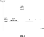
- Figure 1 shows an example of a bandwidth part scenario, where 3 different BWPs are configured: BWP 1 with a width of 40 MHz and subcarrier spacing of 15 kHz; BWP 2 with a width of 10 MHz and subcarrier spacing of 15 kHz; and BWP 3 with a width of 20 MHz and subcarrier spacing of 60 kHz.
- the gNB configures the UE with uplink and downlink BWPs.
- the gNB configures the UE with at least downlink BWPs on the SCells. In other words, there may be no uplink BWPs, in some cases.
- the initial BWP is the BWP used for initial access.
- the initial BWP is the BWP configured for the UE to first operate at SCell activation.
- the BWP for downlink and uplink can be switched independently of one another.
- time division duplex (TDD) operation the BWP for downlink and uplink is switched simultaneously. Switching between configured BWPs happens by means of downlink control information (DCI) or an inactivity timer (L1 signaling).
- DCI downlink control information
- L1 signaling an inactivity timer
- the UE does not monitor the physical downlink control channel (PDCCH), does not transmit on the physical uplink control channel (PUCCH), physical random access channel (PRACH) and uplink shared channel (UL-SCH).
- PDCCH physical downlink control channel
- PUCCH physical uplink control channel
- PRACH physical random access channel
- UL-SCH uplink shared channel
- MAC control elements (MAC CE)
- MAC control elements are control commands within the MAC layer, exchanged between the UE and the network. These special MAC structures carrying the control information are implemented as a special bit string in the logical channel ID (LCID) field of a MAC Header (see 3GPP TS 38.321). There are several MAC CEs in downlink MAC and also several MAC CEs in uplink MAC.
- LCID logical channel ID
- the network may activate and deactivate the configured channel state information reference signal (CSI-RS) resources of a serving cell by sending the Activation/Deactivation of CSI-RS resources MAC control element.
- CSI-RS channel state information reference signal
- a set of semi-persistent CSI report settings are configured, by higher layers, and the CSI request field in a DCI command activates one of the semi-persistent CSI reports.
- a set of semi-persistent CSI report settings are configured, by higher layers, with the PUCCH resource used for transmitting the CSI report.
- Semi-persistent reporting on PUCCH is activated by a MAC CE activation command, which selects one of the semi-persistent CSI Report settings for use by the UE on the PUCCH.
- a UE with the higher layer parameter ResourceConfigType set to "semi-persistent" receives a MAC CE activation command for CSI-RS resources for channel measurement and CSI-interference measurement (IM)/non-zero power (NZP) CSI-RS resources for interference measurement associated with configured CSI resource settings in slot n
- the corresponding actions in 3GPP TS 38.321 and the UE assumptions (including quasico-location assumptions provided by a reference to a TCI-RS-SetConfig ) on CSI-RS/CSI-IM transmission corresponding to the configured CSI-RS/CSI-IM resource configurations shall be applied no later than the minimum requirement defined in 3GPP TS 38.133.
- a UE When a UE receives a MAC CE deactivation command as described in 3GPP TS 38.321 for activated CSI-RS/CSI-IM resources associated with configured CSI resource settings in slot n, the corresponding actions in 3GPP TS 38.321 and UE assumption on cessation of CSI-RS/CSI-IM transmission corresponding to the deactivated CSI-RS/CSI-IM resources shall apply no later than the minimum requirement defined in 3GPP TS 38.133.
- the UE may assume that the CSI-RS resources for channel measurement and the CSI-IM/NZP CSI-RS resources for interference measurement are spatially quasi co-located. It is worth noting that a similar procedure may be applied also when configuring sounding reference signal (SRS) resources and transmission configuration indication (TCI)-States (i.e., for antenna ports quasi-colocation).
- SRS sounding reference signal
- TCI transmission configuration indication
- MAC CE commands are used for PDSCH and PUSCH related procedures.
- a UE can be configured with higher layer signaling for up to M TCI-States to decode PDSCH according to a detected PDCCH, with DCI intended for the UE and the given serving cell, where M depends on the UE capability.
- M depends on the UE capability.
- How these TCI-States are configured and activated is performed through a MAC CE command (i.e., in 3GPP TS 38.321) used to map up to 8 TCI states to the codepoints of the DCI field TCI-states.
- semi-persistent CSI reporting can be activated/deactivated through MAC CE commands.
- a CSI reporting triggering state can be associated with either candidate downlink BWP.
- a UE is not expected to be triggered with a CSI report for a non-active downlink BWP.
- the UE can be configured with one or more SRSs linked to each BWP.
- a UE can be configured for operation using only a part of the total cell bandwidth, with this being referred to as a BWP.
- the maximum number of supported BWPs is currently 4.
- Different PDSCH and PUSCH procedures may be configured for each of the BWPs.
- the UE is configured to switch from one BWP to another (this is done through L1 signaling)
- BWPs In the standardization of NR, an open issue with respect to the use of BWPs is the relation between the BWP switching and the operation related to various physical layer procedures/parameters, e.g., regarding CSI-RS and SRS, which are controlled via MAC CE commands. So far, those MAC CE controlled parameters and procedures are associated with a single BWP.
- the UE In the event that the UE is indicated to switch the currently active BWP, the previously activated CSI-RS report or SRS configuration might be invalid for the new "active" BWP. Further, the UE is not allowed to send PHY reports to a BWP that is not active anymore - thus, it may also happen that no PHY report is received by the network once that the UE switches to a new BWP.
- the UE may provide invalid reporting to the network as a result of the misalignment between the currently "active" BWP and the physical layer procedures configured for the previously “active” BWP.
- This problem may apply to any or all of the physical procedures/parameters that can be toggled by MAC CEs.
- NEC "Clarifications on BWP set configuration", vol. RAN WG2, no. Reno, USA; 20171127 - 20171201 17 November 2017 (2017-11-17), XP051372387 , discusses aspects of the BWP including capability related to BWP set configuration and RLM/RRM measurements at BWP switching.
- INTERDIGITAL ET AL "Details of BWP switching operation",vol. RAN WG1, no. Vancouver, Canada; 20180122 - 20180126 12 January 2018 (2018-01-12), XP051384478 , discusses UE BWP switching acknowledgement in the form of aperiodic CSI reporting requested implicitly by the scheduling DCI.
- VIVO "Other aspects on bandwidth Parts", vol. RAN WG1, no. Reno, USA; 20171127 - 20171201 18 November 2017 (2017-11-18), XP051369543 , discusses remaining issues on BWP activation/ deactivation, such as the exact procedure for BWP activation/deactivation with DCI and the UL scheduling issue with timer based BWP switching.
- Embodiments of the present invention prevent this misalignment between the active BWP and related physical layer procedures that may arise due to BWP switching. This keeps the NR performance at the expected level.
- IEs information elements
- a ServingCellConfigCommon IE may be used to configure cell-specific parameters of a UE's serving cell, including, for example, an initial downlink BWP.
- the IE contains parameters which a UE would typically acquire from Standard Signal Block (SSB), Master Information Block (MIB) or System Information Blocks (SIBs) when accessing the cell from IDLE.
- SIBs System Information Blocks
- the network provides this information in dedicated signaling when configuring a UE with SCells or with an additional cell group (SCG).
- the ServingCellConfig IE may be used to configure (add or modify) the UE with a serving cell, which may be the SpCell or an SCell of an MCG or SCG. This may involve specifying initial downlink BWPs (common and dedicated), initial uplink BWPs (common and dedicated), a first active downlink BWP, a duration or timer after which the UE falls back to a default BWP, and a default downlink BWP.
- the BandwidthPart-Config IE information element involves configuration of a BWP.
- This IE can include an identifier, frequency domain location and bandwidth. The location is given as a distance (in number of physical resource blocks) in relation to the lowest usable subcarrier with the same subcarrier spacing as the BWP.
- the IE may specify uplink and downlink BWPs, whether common or dedicated, for physical channels. Conditions may also be specified.
- PHY layer procedures activated/deactivated by MAC CE include semi-persistent CSI-RS reporting, the procedures and/or parameters for which may vary on a per BWP basis.
- the UE can be configured through MAC CE with one or more SRS resources per BWP.
- Another procedure with which the UE can be configured on a per BWP basis is the TCI state (one or more) in order to decode PDSCH according to a detected PDCCH.
- TCI state one or more
- the UE is not allowed to send PHY reports to a BWP that is not active anymore. Thus, it may also happen that no PHY report is received by the network once the UE switches to a new BWP.
- the techniques disclosed herein address UE behaviors and configurations that may resolve this issue.
- a UE is configured by the network with default PHY layer procedures (e.g., CSI-RS, SRS reports), either on a dedicated basis, for each possible BWP, or on a common basis, for all BWPs.
- PHY layer procedures e.g., CSI-RS, SRS reports
- the default configuration can be signaled by means of RRC.
- the RRC messages that may contain or indicate the default configuration could be RRC reconfiguration, RRC resume, or RRC connection setup messages.
- the default PHY layer configuration may be immediately applied and used when the active BWP is changed from, e.g., BWPa to BWPb. This way, a possible misalignment of the new active BWP and the previously configured PHY layer procedures and associated parameters, which are configured by MAC CE, can be avoided.
- the UE may not have any default PHY layer configuration for BWPs.
- the UE may stop previously configured PHY layer procedures (i.e., one or more of those that are activated/deactivated and/or configured by MAC CE) upon BWP switching, and wait for a new MAC CE command for the new active BWP.
- the UE starts a timer (e.g., MacCeBWPTimer ) upon BWP switching and, when the maximum value is reached and no new MAC CE command has been received by the UE, the UE reverts to the default PHY layer configuration for the newly active BWP.
- the UE reverts to the default BWP, with its associated default PHY layer configuration, upon expiration of the timer with no receipt of a MAC CE command configuring the PHY layer parameters or procedures.
- the UE can apply Radio Link Failure (RLF) and/or re-establishment procedures upon expiration of the timer (e.g., if there is no default configuration for the newly active BWP).
- RLF Radio Link Failure
- the network could start a counter where the not-received PHY layer reports are counted.
- the PHY layer reports can involve CSI-RS, SRS, TCI-States, or other L1 information.
- whether or not there is a default PHY layer configuration for the new BWP if the UE has previously used the same active BWP, it can revert to the PHY layer procedures and associated parameters previously configured (by MAC CE) for the same BWP. In other words, the previous MAC CE indication/configuration for the same BWP can be reused as a default PHY layer configuration when it is configured for the next time. Put another way, once a PHY layer configuration for a given BWP is made, it can be considered as the default configuration for that BWP until it is altered, in some embodiments.
- this reversion to a previous configuration for a given BWP may be valid only temporarily, for instance, if the UE did not have a state transition from active to idle (or inactive) and a handover to another cell (or BS), or either of these. In some of these embodiments, the UE may revert to a configured default outside of this validity period, if one is available.
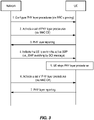
- Figure 2 illustrates a signaling flow where, upon BWP switching, the UE reverts to default PHY layer configuration for the BWP.
- the UE reverts to default PHY layer configuration for the BWP.
- the UE starts to send PHY layer reporting to the network.
- the PHY layer reporting types can be configured as CSI-RS, SRS, TCI-States, or other L1 information reporting. Further, all this reporting can be configured for a single BWP.
- the network sends a DCI command to the UE (L1 signaling) to change the "active" BWP, as shown at step 4, the UE, to avoid misalignment due to the PHY layer reporting linked to the old BWP, autonomously reverts to the default configuration for the BWP, as shown at steps 5 and 6. Reverting to the default configuration for the BWP implies that also PHY layer procedures/parameters related to this BWP are used.
- the network subsequently explicitly activates a set of PHY layer procedures, via MAC CE, as shown at step 7, after which the subsequent PHY layer reporting, at step 8, is performed according to the newly activated procedures.
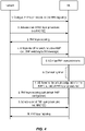
- FIG 3 illustrates a signaling flow, where upon BWP switching, the UE stops PHY layer procedures and waits for a new MAC CE.
- the UE stops PHY layer procedures and waits for a new MAC CE.
- the UE starts to send PHY layer reporting to the network.
- the PHY layer reporting can involve CSI-RS, SRS, TCI-States, or other L1 information. Further, all these reporting can be configured for a single BWP.
- the UE stops all the PHY layer procedures configured for the old BWP, as shown at step 4.
- the network after sending the DCI command to UE for switching from BWPa to a BWPb, sends also a MAC CE to explicitly configure the PHY layer procedures for the new BWP.
- the network could start a counter where the not-received PHY layer reports are counted.
- the PHY layer reports can involve CSI-RS, SRS, TCI-States, or other L1 information.
- the network could re-send the MAC CE to configure the PHY layer procedures for the new BWP.
- Figure 4 illustrates a signaling flow, where upon BWP switching, the UE stops the PHY layer procedure and starts a time. When it expires, the UE reverts to the default PHY layer configuration for the BWP.
- the UE starts to send PHY layer reporting to the network.
- the PHY layer reporting can involve CSI-RS, SRS, TCI-States, or other L1 information. Further, all this reporting can be configured for a single BWP.
- the UE stops all the PHY layer procedures configured for the old BWP, as shown at step 5.
- UE starts a waiting timer, as shown at step 6, during which a MAC CE command with the new PHY layer procedures/parameters can be received by the network.
- the BWP-InactivityTimer can be used or a new timer (e.g., MacCeBWPTimer ) can be configured.
- the UE if the UE receives a MAC CE command with the PHY layer procedure for the new active BWP, the new reporting based on this configuration is applied. Alternatively, if no MAC CE is received and the waiting timer expires, the UE reverts autonomously to the default configuration for the BWP, e.g., as shown at step 7 of Figure 4 . Reverting to the default configuration for the BWP implies that also PHY layer procedures related to this BWP are used. Alternatively (if there is no default configuration), a re-establishment procedure may be triggered.
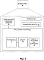
- Figure 5 shows a network node 30, such as a base station, which may be configured to carry out one or more of these disclosed techniques.
- the base station may be an evolved Node B (eNodeB), Node B or gNB. These operations can be performed by other kinds of network nodes or relay nodes.
- eNodeB evolved Node B
- gNB Node B
- These operations can be performed by other kinds of network nodes or relay nodes.
- the network node 30 will be described as being configured to operate as a cellular network access node in an LTE network or NR network.
- each type of node may be adapted to carry out one or more of the methods and signaling processes described herein, e.g., through the modification of and/or addition of appropriate program instructions for execution by processing circuits 32.
- the network node 30 facilitates communication between wireless terminals, other network access nodes and/or the core network.
- the network node 30 may include communication interface circuitry 38 that includes circuitry for communicating with other nodes in the core network, radio nodes, and/or other types of nodes in the network for the purposes of providing data and/or cellular communication services.
- the network node 30 communicates with wireless devices using antennas 34 and transceiver circuitry 36.
- the transceiver circuitry 36 may include transmitter circuits, receiver circuits, and associated control circuits that are collectively configured to transmit and receive signals according to a radio access technology, for the purposes of providing cellular communication services.
- the network node 30 also includes one or more processing circuits 32 that are operatively associated with the transceiver circuitry 36 and, in some cases, the communication interface circuitry 38.
- the processing circuitry 32 comprises one or more digital processors 42, e.g., one or more microprocessors, microcontrollers, Digital Signal Processors (DSPs), Field Programmable Gate Arrays (FPGAs), Complex Programmable Logic Devices (CPLDs), Application Specific Integrated Circuits (ASICs), or any mix thereof. More generally, the processing circuitry 32 may comprise fixed circuitry, or programmable circuitry that is specially configured via the execution of program instructions implementing the functionality taught herein, or may comprise some mix of fixed and programmed circuitry.
- the processor 42 may be multi-core, i.e., having two or more processor cores utilized for enhanced performance, reduced power consumption, and more efficient simultaneous processing of multiple tasks.
- the processing circuitry 32 also includes a memory 44.
- the memory 44 stores one or more computer programs 46 and, optionally, configuration data 48.
- the memory 44 provides non-transitory storage for the computer program 46 and it may comprise one or more types of computer-readable media, such as disk storage, solid-state memory storage, or any mix thereof.
- non-transitory means permanent, semi-permanent, or at least temporarily persistent storage and encompasses both long-term storage in non-volatile memory and storage in working memory, e.g., for program execution.
- the memory 44 comprises any one or more of SRAM, DRAM, EEPROM, and FLASH memory, which may be in the processing circuitry 32 and/or separate from the processing circuitry 32.
- the memory 44 may also store any configuration data 48 used by the network access node 30.
- the processing circuitry 32 may be configured, e.g., through the use of appropriate program code stored in memory 44, to carry out one or more of the methods and/or signaling processes detailed hereinafter.
- the processing circuitry 32 of the network node 30 is configured, according to some embodiments, to serve a wireless device configured to selectively operate in one of two or more previously configured BWPs, where each BWP being a different subset of an available bandwidth for uplink and/or downlink operation.
- the processing circuitry 32 of the network node 30 is also configured to send, to the wireless device, an indication to switch from use of a first BWP to a second BWP and count a number of physical layer reports expected from the wireless device during use of the second BWP but not received.
- the processing circuitry 32 is configured to, responsive to the number reaching a predetermined limit, send one or more MAC CEs to configure physical layer reporting for the second BWP.
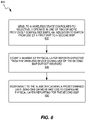
- the processing circuitry 32 of the network node 30 may also be configured to perform a corresponding method 600, as shown in Figure 6 .
- the method 600 includes sending, to the wireless device, an indication to switch from use of a first BWP to a second BWP (block 602) and counting a number of physical layer reports expected from the wireless device during use of the second BWP but not received (block 604).
- the method 600 also includes, responsive to the number reaching a predetermined limit, sending one or more MAC CEs to configure physical layer reporting for the second BWP (block 606).
- the method 600 may further include sending one or more first MAC CEs to configure physical layer reporting for the second BWP, subsequent to sending the indication to switch from use of the first BWP to the second BWP, wherein said counting begins upon sending the one or more first MAC CEs.
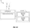
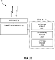
- FIG. 7 illustrates a diagram of a wireless device, shown as wireless device 50, according to some embodiments.
- the wireless device 50 may be considered to represent any wireless terminals that may operate in a network, such as a UE in a cellular network.
- Other examples may include a communication device, target device, device to device (D2D) UE, machine type UE or UE capable of machine to machine communication (M2M), a sensor equipped with UE, PDA (personal digital assistant), Tablet, mobile terminal, smart phone, laptop embedded equipped (LEE), laptop mounted equipment (LME), USB dongles, Customer Premises Equipment (CPE), etc.
- D2D device to device
- M2M machine to machine communication
- PDA personal digital assistant
- Tablet mobile terminal
- smart phone laptop embedded equipped (LEE)
- LME laptop mounted equipment
- CPE Customer Premises Equipment
- the wireless device 50 is configured to communicate with a radio network node or base station in a wide-area cellular network via antennas 54 and transceiver circuitry 56.
- the transceiver circuitry 56 may include transmitter circuits, receiver circuits, and associated control circuits that are collectively configured to transmit and receive signals according to a radio access technology, for the purposes of using cellular communication services.
- This radio access technologies are NR and LTE for the purposes of this discussion.
- the wireless device 50 also includes one or more processing circuits 52 that are operatively associated with the radio transceiver circuitry 56.
- the processing circuitry 52 comprises one or more digital processing circuits, e.g., one or more microprocessors, microcontrollers, DSPs, FPGAs, CPLDs, ASICs, or any mix thereof. More generally, the processing circuitry 52 may comprise fixed circuitry, or programmable circuitry that is specially adapted via the execution of program instructions implementing the functionality taught herein, or may comprise some mix of fixed and programmed circuitry.
- the processing circuitry 52 may be multi-core.
- the processing circuitry 52 also includes a memory 64.
- the memory 64 stores one or more computer programs 66 and, optionally, configuration data 68.
- the memory 64 provides non-transitory storage for the computer program 66 and it may comprise one or more types of computer-readable media, such as disk storage, solid-state memory storage, or any mix thereof.
- the memory 64 comprises any one or more of SRAM, DRAM, EEPROM, and FLASH memory, which may be in the processing circuitry 52 and/or separate from processing circuitry 52.
- the memory 64 may also store any configuration data 68 used by the wireless device 50.
- the processing circuitry 52 may be configured, e.g., through the use of appropriate program code stored in memory 64, to carry out one or more of the methods and/or signaling processes detailed hereinafter.
- the processing circuitry 52 of the wireless device 50 is configured, according to some embodiments, to selectively operate in one of two or more previously configured BWPs, where each BWP being a different subset of an available bandwidth for uplink and/or downlink operation.
- the processing circuitry 52 is configured to receive an indication to switch from use of a first BWP to a second BWP, and after switching to use of the second BWP, apply a predetermined default configuration, corresponding to the second BWP, to one or more physical layer parameters and/or procedures.
- the processing circuitry 52 is configured to receive an indication to switch from use of a first BWP to a second BWP and determine whether physical layer parameters and/or procedures for the second BWP have previously been configured by MAC CEs during prior use of the second BWP.
- the processing circuitry 52 is also configured to apply the previously configured physical layer parameters and/or procedures for the second BWP upon determining that the physical layer parameters and/or procedures for the second BWP have previously been configured by MAC CEs during prior use of the second BWP.
- the processing circuitry 52 is configured to receive an indication to switch from use of a first BWP to a second BWP and upon switching to use of the second BWP, stop operation of one or more physical layer procedures until receipt of a command activating and/or configuring the stopped one or more physical layer procedures for the second BWP.
- the processing circuitry 52 is configured to receive an indication to switch from use of a first BWP to a second BWP, and upon switching to use of the second BWP, stop operation of one or more physical layer procedures and waiting a predetermined time for receipt of a command activating and/or configuring the stopped one or more physical layer procedures for the second BWP.
- the processing circuitry 52 is configured to, upon failing to receive a command activating and/or configuring the stopped one or more physical layer procedures for the second BWP, within the predetermined time, switch to use of a default BWP of the two or more previously configured BWPs and apply a predetermined default configuration, corresponding to the default BWP, to one or more physical layer parameters and/or procedures.
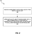
- method 800 includes receiving an indication to switch from use of a first BWP to a second BWP (block 802), and after switching to use of the second BWP, applying a predetermined default configuration, corresponding to the second BWP, to one or more physical layer parameters and/or procedures (block 804).
- the predetermined default configuration may be one of a plurality of predetermined default configurations, each of the predetermined default configurations uniquely corresponding to a respective one of the previously configured BWPs.
- the predetermined default configuration may be a common default configuration corresponding to two or more of the previously configured BWPs, including the second BWP.
- the predetermined default configuration may be applied immediately upon switching to use of the second BWP.
- the method 800 further includes, upon switching to use of the second BWP, stopping operation of one or more physical layer procedures.
- the method 800 also includes waiting a predetermined time for receipt of a command activating and/or configuring the stopped one or more physical layer procedures for the second BWP.
- the applying of the predetermined default configuration may be performed upon failing to receive a command activating and/or configuring the stopped one or more physical layer procedures for the second BWP, within the predetermined time.
- the method 800 may also include, upon switching to use of the second BWP, determining whether physical layer parameters and/or procedures for the second BWP have previously been configured by MAC CEs during prior use of the second BWP.
- the applying of the predetermined default configuration may be performed upon determining that physical layer parameters and/or procedures for the second BWP have not previously been configured by MAC CEs during prior use of the second BWP.
- the method 800 may further include, upon switching to use of the second BWP, determining whether physical layer parameters and/or procedures for the second BWP have previously been configured by MAC CEs during prior use of the second BWP and within a predetermined interval prior to said switching.
- the applying of the predetermined default configuration may be performed upon determining that physical layer parameters and/or procedures for the second BWP have not previously been configured by MAC CEs during prior use of the second BWP and within the predetermined interval.
- the method 800 may include, upon switching to use of the second BWP, determining whether physical layer parameters and/or procedures for the second BWP have previously been configured by MAC CEs during prior use of the second BWP that occurred without either a change in state from active to idle or a handover.
- the applying of the predetermined default configuration may be performed upon determining that physical layer parameters and/or procedures for the second BWP have not previously been configured by MAC CEs during prior use of the second BWP that occurred without either a change in state from active to idle or a handover.
- the method 800 may include, subsequently to applying the predetermined default configuration, receiving a command activating and/or configuring one or more physical layer procedures for the second BWP, and performing the one or more physical layer procedures according to the received command.
- the method 900 includes receiving an indication to switch from use of a first BWP to a second BWP (block 902) and determining whether physical layer parameters and/or procedures for the second BWP have previously been configured by medium access control MAC CEs during prior use of the second BWP (block 904).
- the method 900 includes applying the previously configured physical layer parameters and/or procedures for the second BWP upon determining that the physical layer parameters and/or procedures for the second BWP have previously been configured by MAC CEs during prior use of the second BWP (block 906).
- the applying of the previously configured physical layer parameters and/or procedures for the second BWP may be further conditioned upon determining that these previously configured physical layer parameters and/or procedures for the second BWP were configured within a predetermined time interval prior to switching from the first BWP to the second BWP.
- the applying the previously configured physical layer parameters and/or procedures for the second BWP may be further conditioned upon determining that no change from active state to idle state and/or no handover has occurred since the previously configured physical layer parameters and/or procedures for the second BWP were configured.
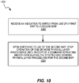
- the method 1000 may include receiving an indication to switch from use of a first BWP to a second BWP (block 1002) and, upon switching to use of the second BWP, stopping operation of one or more physical layer procedures until receipt of a command activating and/or configuring the stopped one or more physical layer procedures for the second BWP (block 1004).
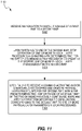
- the method 1100 includes receiving an indication to switch from use of a first BWP to a second BWP (block 1102), and upon switching to use of the second BWP, stopping operation of one or more physical layer procedures and waiting a predetermined time for receipt of a command activating and/or configuring the stopped one or more physical layer procedures for the second BWP (block 1104).
- the method 1100 also includes, upon failing to receive a command activating and/or configuring the stopped one or more physical layer procedures for the second BWP, within the predetermined time, switching to use of a default BWP of the two or more previously configured BWPs and applying a predetermined default configuration, corresponding to the default BWP, to one or more physical layer parameters and/or procedures (block 1106).
- the physical layer parameters and/or procedures include CSI reporting, interference measurement reporting and/or SRS configuration parameters.
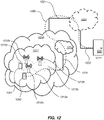
- Figure 12 illustrates a communication system that includes a telecommunication network 1210, such as a 3GPP-type cellular network, which comprises an access network 1211, such as a radio access network, and a core network 1214.
- the access network 1211 comprises a plurality of base stations 812a, 1212b, 1212c, such as NBs, eNBs, gNBs or other types of wireless access points, each defining a corresponding coverage area 1213a, 1213b, 1213c.
- Each base station 1212a, 1212b, 1212c is connectable to the core network 1214 over a wired or wireless connection 1215.
- a first user equipment (UE) 1291 located in coverage area 1213c is configured to wirelessly connect to, or be paged by, the corresponding base station 1212c.
- a second UE 1292 in coverage area 1213a is wirelessly connectable to the corresponding base station 1212a. While a plurality of UEs 1291, 1292 are illustrated in this example, the disclosed embodiments are equally applicable to a situation where a sole UE is in the coverage area or where a sole UE is connecting to the corresponding base station 1212.
- the telecommunication network 1210 is itself connected to a host computer 1230, which may be embodied in the hardware and/or software of a standalone server, a cloud-implemented server, a distributed server or as processing resources in a server farm.
- the host computer 1230 may be under the ownership or control of a service provider, or may be operated by the service provider or on behalf of the service provider.
- the connections 1221, 1222 between the telecommunication network 1210 and the host computer 1230 may extend directly from the core network 1214 to the host computer 1230 or may go via an optional intermediate network 1220.
- the intermediate network 1220 may be one of, or a combination of more than one of, a public, private or hosted network; the intermediate network 1220, if any, may be a backbone network or the Internet; in particular, the intermediate network 1220 may comprise two or more sub-networks (not shown).
- the communication system of Figure 12 as a whole enables connectivity between one of the connected UEs 1291, 1292 and the host computer 1230.
- the connectivity may be described as an over-the-top (OTT) connection 1250.
- the host computer 1230 and the connected UEs 1291, 1292 are configured to communicate data and/or signaling via the OTT connection 1250, using the access network 1211, the core network 1214, any intermediate network 1220 and possible further infrastructure (not shown) as intermediaries.
- the OTT connection 1250 may be transparent in the sense that the participating communication devices through which the OTT connection 1250 passes are unaware of routing of uplink and downlink communications.
- a base station 1212 may not or need not be informed about the past routing of an incoming downlink communication with data originating from a host computer 1230 to be forwarded (e.g., handed over) to a connected UE 1291. Similarly, the base station 1212 need not be aware of the future routing of an outgoing uplink communication originating from the UE 1291 towards the host computer 1230.
- a host computer 1310 comprises hardware 1315 including a communication interface 1316 configured to set up and maintain a wired or wireless connection with an interface of a different communication device of the communication system 1300.
- the host computer 1310 further comprises processing circuitry 1318, which may have storage and/or processing capabilities.
- the processing circuitry 1318 may comprise one or more programmable processors, application-specific integrated circuits, field programmable gate arrays or combinations of these (not shown) adapted to execute instructions.
- the host computer 1310 further comprises software 1311, which is stored in or accessible by the host computer 1310 and executable by the processing circuitry 1318.
- the software 1311 includes a host application 1312.
- the host application 1312 may be operable to provide a service to a remote user, such as a UE 1330 connecting via an OTT connection 1350 terminating at the UE 1330 and the host computer 1310. In providing the service to the remote user, the host application 1312 may provide user data which is transmitted using the OTT connection 1350.
- the communication system 1300 further includes a base station 1320 provided in a telecommunication system and comprising hardware 1325 enabling it to communicate with the host computer 1310 and with the UE 1330.
- the hardware 1325 may include a communication interface 1326 for setting up and maintaining a wired or wireless connection with an interface of a different communication device of the communication system 1300, as well as a radio interface 1327 for setting up and maintaining at least a wireless connection 1370 with a UE 1330 located in a coverage area (not shown in Figure 13 ) served by the base station 1320.
- the communication interface 1326 may be configured to facilitate a connection 1360 to the host computer 1310.
- connection 1360 may be direct or it may pass through a core network (not shown in Figure 13 ) of the telecommunication system and/or through one or more intermediate networks outside the telecommunication system.
- the hardware 1325 of the base station 1320 further includes processing circuitry 1328, which may comprise one or more programmable processors, application-specific integrated circuits, field programmable gate arrays or combinations of these (not shown) adapted to execute instructions.
- the base station 1320 further has software 1321 stored internally or accessible via an external connection.
- the communication system 1300 further includes the UE 1330 already referred to.
- Its hardware 1335 may include a radio interface 1337 configured to set up and maintain a wireless connection 1370 with a base station serving a coverage area in which the UE 1330 is currently located.
- the hardware 1335 of the UE 1330 further includes processing circuitry 1338, which may comprise one or more programmable processors, application-specific integrated circuits, field programmable gate arrays or combinations of these (not shown) adapted to execute instructions.
- the UE 1330 further comprises software 1331, which is stored in or accessible by the UE 1330 and executable by the processing circuitry 1338.
- the software 1331 includes a client application 1332.
- the client application 1332 may be operable to provide a service to a human or non-human user via the UE 1330, with the support of the host computer 1310.
- an executing host application 1312 may communicate with the executing client application 1332 via the OTT connection 1350 terminating at the UE 1330 and the host computer 1310.
- the client application 1332 may receive request data from the host application 1312 and provide user data in response to the request data.
- the OTT connection 1350 may transfer both the request data and the user data.
- the client application 1332 may interact with the user to generate the user data that it provides.
- the host computer 1310, base station 1320 and UE 1330 illustrated in Figure 13 may be identical to the host computer 1230, one of the base stations 1212a, 1212b, 1212c and one of the UEs 1291, 1292 of Figure 12 , respectively.
- the inner workings of these entities may be as shown in Figure 13 and independently, the surrounding network topology may be that of Figure 12 .
- the OTT connection 1350 has been drawn abstractly to illustrate the communication between the host computer 1310 and the use equipment 1330 via the base station 1320, without explicit reference to any intermediary devices and the precise routing of messages via these devices.
- Network infrastructure may determine the routing, which it may be configured to hide from the UE 1330 or from the service provider operating the host computer 1310, or both. While the OTT connection 1350 is active, the network infrastructure may further take decisions by which it dynamically changes the routing (e.g., on the basis of load balancing consideration or reconfiguration of the network).
- the wireless connection 1370 between the UE 1330 and the base station 1320 is in accordance with the teachings of the embodiments described throughout this disclosure, such as provided by nodes such as wireless device 50 and network node 30, along with the corresponding methods 600 and 800-1100.
- the misalignment of the active BWP and associated physical layer configuration results in suboptimal performance and possible erroneous behavior.
- the various embodiments described herein avoids the misalignment and keeps the NR performance in the expected level. This improves the data rate, capacity, latency and/or power consumption for the network and UE 1330 using the OTT connection 1350 and thereby provide benefits such as reduced user waiting time, more capacity, better responsiveness, and better device battery time.
- a measurement procedure may be provided for the purpose of monitoring data rate, latency and other factors on which the one or more embodiments improve.
- the measurement procedure and/or the network functionality for reconfiguring the OTT connection 1350 may be implemented in the software 1311 of the host computer 1310 or in the software 1331 of the UE 1330, or both.
- sensors (not shown) may be deployed in or in association with communication devices through which the OTT connection 1350 passes; the sensors may participate in the measurement procedure by supplying values of the monitored quantities exemplified above, or supplying values of other physical quantities from which software 1311, 1331 may compute or estimate the monitored quantities.
- the reconfiguring of the OTT connection 1350 may include message format, retransmission settings, preferred routing etc.; the reconfiguring need not affect the base station 1320, and it may be unknown or imperceptible to the base station 1320. Such procedures and functionalities may be known and practiced in the art.
- measurements may involve proprietary UE signaling facilitating the host computer's 1310 measurements of throughput, propagation times, latency and the like.
- the measurements may be implemented in that the software 1311, 1331 causes messages to be transmitted, in particular empty or 'dummy' messages, using the OTT connection 1350 while it monitors propagation times, errors etc.
- FIG 14 is a flowchart illustrating a method implemented in a communication system, in accordance with one embodiment.
- the communication system includes a host computer, a base station and a UE which may be those described with reference to Figures 12 and 13 .
- the host computer provides user data.
- the host computer provides the user data by executing a host application.
- the host computer initiates a transmission carrying the user data to the UE.
- the base station transmits to the UE the user data which was carried in the transmission that the host computer initiated, in accordance with the teachings of the embodiments described throughout this disclosure.
- the UE executes a client application associated with the host application executed by the host computer.
- FIG. 15 is a flowchart illustrating a method implemented in a communication system, in accordance with one embodiment.
- the communication system includes a host computer, a base station and a UE which may be those described with reference to Figures 12 and 13 .
- the host computer provides user data.
- the host computer provides the user data by executing a host application.
- the host computer initiates a transmission carrying the user data to the UE. The transmission may pass via the base station, in accordance with the teachings of the embodiments described throughout this disclosure.
- the UE receives the user data carried in the transmission.
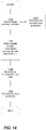
- FIG 16 is a flowchart illustrating a method implemented in a communication system, in accordance with one embodiment.
- the communication system includes a host computer, a base station and a UE which may be those described with reference to Figures 12 and 13 .
- the UE receives input data provided by the host computer.
- the UE provides user data.
- the UE provides the user data by executing a client application.
- the UE executes a client application which provides the user data in reaction to the received input data provided by the host computer.
- the executed client application may further consider user input received from the user.
- the UE initiates, in an optional third substep 1630, transmission of the user data to the host computer.
- the host computer receives the user data transmitted from the UE, in accordance with the teachings of the embodiments described throughout this disclosure.
- FIG 17 is a flowchart illustrating a method implemented in a communication system, in accordance with one embodiment.
- the communication system includes a host computer, a base station and a UE which may be those described with reference to Figures 12 and 13 .
- the base station receives user data from the UE.
- the base station initiates transmission of the received user data to the host computer.
- the host computer receives the user data carried in the transmission initiated by the base station.
- a communication system including a host computer comprises processing circuitry configured to provide user data and a communication interface configured to forward the user data to a cellular network for transmission to a UE configured to selectively operate in one of two or more previously configured BWPs, each BWP being a different subset of an available bandwidth for uplink and/or downlink operation.
- the cellular network comprises a base station configured to serve the UE and configured to send, to the UE, an indication to switch from use of a first BWP to a second BWP and count a number of physical layer reports expected from the UE during use of the second BWP but not received.
- the base station Responsive to the number reaching a predetermined limit, the base station sends one or more MAC CEs to configure physical layer reporting for the second BWP.
- the communication system may include the base station and/or the UE configured to communicate with the base station.
- the processing circuitry of the host computer may be configured to execute a host application, thereby providing the user data, and the UE may comprise processing circuitry configured to execute a client application associated with the host application.
- a method implemented in a communication system including a host computer, a base station and a UE configured to selectively operate in one of two or more previously configured BWPs, each BWP being a different subset of an available bandwidth for uplink and/or downlink operation, comprises, at the host computer, providing user data and, at the host computer, initiating a transmission carrying the user data to the UE via a cellular network comprising the base station, configured to serve the UE.
- the method at the base station comprises sending, to the UE, an indication to switch from use of a first BWP to a second BWP, counting a number of physical layer reports expected from the UE during use of the second BWP but not received and, responsive to the number reaching a predetermined limit, sending one or more MAC control elements CEs to configure physical layer reporting for the second BWP.
- the method may further comprise, at the base station, transmitting the user data.
- the user data may be provided at the host computer by executing a host application, the method further comprising, at the UE, executing a client application associated with the host application.
- a communication system including a host computer comprises processing circuitry configured to provide user data and a communication interface configured to forward user data to a cellular network for transmission to a UE configured to selectively operate in one of two or more previously configured BWPs, each BWP being a different subset of an available bandwidth for uplink and/or downlink operation, where the UE comprises a radio interface and processing circuitry configured to receive an indication to switch from use of a first BWP to a second BWP and, after switching to use of the second BWP, apply a predetermined default configuration, corresponding to the second BWP, to one or more physical layer parameters and/or procedures.
- a communication system including a host computer comprises processing circuitry configured to provide user data and a communication interface configured to forward user data to a cellular network for transmission to a UE configured to selectively operate in one of two or more previously configured BWPs, each BWP being a different subset of an available bandwidth for uplink and/or downlink operation, where the UE comprises a radio interface and processing circuitry configured to receive an indication to switch from use of a first BWP to a second BWP, determine whether physical layer parameters and/or procedures for the second BWP have previously been configured by MAC CEs during prior use of the second BWP and apply the previously configured physical layer parameters and/or procedures for the second BWP upon determining that the physical layer parameters and/or procedures for the second BWP have previously been configured by MAC CEs during prior use of the second BWP.
- a communication system including a host computer comprises processing circuitry configured to provide user data and a communication interface configured to forward user data to a cellular network for transmission to a UE configured to selectively operate in one of two or more previously configured BWPs, each BWP being a different subset of an available bandwidth for uplink and/or downlink operation, where the UE comprises a radio interface and processing circuitry configured to receive an indication to switch from use of a first BWP to a second BWP and, upon switching to use of the second BWP, stop operation of one or more physical layer procedures until receipt of a command activating and/or configure the stopped one or more physical layer procedures for the second BWP.
- a communication system including a host computer comprises processing circuitry configured to provide user data and a communication interface configured to forward user data to a cellular network for transmission to a UE configured to selectively operate in one of two or more previously configured BWPs, each BWP being a different subset of an available bandwidth for uplink and/or downlink operation, where the UE comprises a radio interface and processing circuitry configured to receive an indication to switch from use of a first BWP to a second BWP and, upon switching to use of the second BWP, stop operation of one or more physical layer procedures and waiting a predetermined time for receipt of a command activating and/or configuring the stopped one or more physical layer procedures for the second BWP.
- the processing circuitry is also configured to, upon failing to receive a command activating and/or configuring the stopped one or more physical layer procedures for the second BWP, within the predetermined time, switch to use of a default BWP of the two or more previously configured BWPs and apply a predetermined default configuration, corresponding to the default BWP, to one or more physical layer parameters and/or procedures.
- the communication system may further include the UE, and the cellular network may further include a base station configured to communicate with the UE.
- the processing circuitry of the host computer may be configured to execute a host application, thereby providing the user data, and the UE's processing circuitry may be configured to execute a client application associated with the host application.
- a method implemented in a communication system including a host computer, a base station and a UE configured to selectively operate in one of two or more previously configured BWPs, each BWP being a different subset of an available bandwidth for uplink and/or downlink operation.
- the method comprises, at the host computer, providing user data and, at the host computer, initiating a transmission carrying the user data to the UE via a cellular network comprising the base station.
- the method comprises, at the UE, receiving an indication to switch from use of a first BWP to a second BWP and, after switching to use of the second BWP, applying a predetermined default configuration, corresponding to the second BWP, to one or more physical layer parameters and/or procedures.
- a method implemented in a communication system including a host computer, a base station and a UE configured to selectively operate in one of two or more previously configured BWPs, each BWP being a different subset of an available bandwidth for uplink and/or downlink operation.
- the method comprises, at the host computer, providing user data and, at the host computer, initiating a transmission carrying the user data to the UE via a cellular network comprising the base station, where the method comprises, at the UE, receiving an indication to switch from use of a first BWP to a second BWP and determining whether physical layer parameters and/or procedures for the second BWP have previously been configured by MAC CEs during prior use of the second BWP.
- the method at the UE also comprises applying the previously configured physical layer parameters and/or procedures for the second BWP upon determining that the physical layer parameters and/or procedures for the second BWP have previously been configured by MAC CEs during prior use of the second BWP.
- a method implemented in a communication system including a host computer, a base station and a UE configured to selectively operate in one of two or more previously configured BWPs, each BWP being a different subset of an available bandwidth for uplink and/or downlink operation.
- the method comprises, at the host computer, providing user data and, at the host computer, initiating a transmission carrying the user data to the UE via a cellular network comprising the base station, where the method comprises, at the UE, receiving an indication to switch from use of a first BWP to a second BWP and, upon switching to use of the second BWP, stopping operation of one or more physical layer procedures until receipt of a command activating and/or configuring the stopped one or more physical layer procedures for the second BWP.
- a method implemented in a communication system including a host computer, a base station and a UE configured to selectively operate in one of two or more previously configured BWPs, each BWP being a different subset of an available bandwidth for uplink and/or downlink operation, the method comprising, at the host computer, providing user data and, at the host computer, initiating a transmission carrying the user data to the UE via a cellular network comprising the base station, where the method comprises, at the UE, receiving an indication to switch from use of a first BWP to a second BWP and upon switching to use of the second BWP, stopping operation of one or more physical layer procedures and waiting a predetermined time for receipt of a command activating and/or configuring the stopped one or more physical layer procedures for the second BWP.
- the method at the UE also comprises, upon failing to receive a command activating and/or configuring the stopped one or more physical layer procedures for the second BWP, within the predetermined time, switching to use of a default BWP of the two or more previously configured BWPs and applying a predetermined default configuration, corresponding to the default BWP, to one or more physical layer parameters and/or procedures.
- the method at the UE may further comprise receiving the user data from the base station.
- a communication system including a host computer comprising a communication interface configured to receive user data originating from a transmission from a UE to a base station, the UE configured to selectively operate in one of two or more previously configured BWPs, each BWP being a different subset of an available bandwidth for uplink and/or downlink operation, and UE's processing circuitry configured to receive an indication to switch from use of a first BWP to a second BWP and, after switching to use of the second BWP, apply a predetermined default configuration, corresponding to the second BWP, to one or more physical layer parameters and/or procedures.
- a communication system including a host computer comprising a communication interface configured to receive user data originating from a transmission from a UE to a base station, the UE configured to selectively operate in one of two or more previously configured BWPs, each BWP being a different subset of an available bandwidth for uplink and/or downlink operation, and UE's processing circuitry configured to receive an indication to switch from use of a first BWP to a second BWP, determine whether physical layer parameters and/or procedures for the second BWP have previously been configured by MAC CEs during prior use of the second BWP and apply the previously configured physical layer parameters and/or procedures for the second BWP upon determining that the physical layer parameters and/or procedures for the second BWP have previously been configured by MAC CEs during prior use of the second BWP.
- a communication system including a host computer comprising a communication interface configured to receive user data originating from a transmission from a UE to a base station, the UE configured to selectively operate in one of two or more previously configured BWPs, each BWP being a different subset of an available bandwidth for uplink and/or downlink operation, and UE's processing circuitry configured to receive an indication to switch from use of a first BWP to a second BWP and, upon switching to use of the second BWP, stop operation of one or more physical layer procedures until receipt of a command activating and/or configuring the stopped one or more physical layer procedures for the second BWP.
- a communication system including a host computer comprising a communication interface configured to receive user data originating from a transmission from a UE to a base station, the UE configured to selectively operate in one of two or more previously configured BWPs, each BWP being a different subset of an available bandwidth for uplink and/or downlink operation, and UE's processing circuitry configured to receive an indication to switch from use of a first BWP to a second BWP and, upon switching to use of the second BWP, stop operation of one or more physical layer procedures and waiting a predetermined time for receipt of a command activating and/or configuring the stopped one or more physical layer procedures for the second BWP.
- the UE's processing circuitry is also configured to, upon failing to receive a command activating and/or configuring the stopped one or more physical layer procedures for the second BWP, within the predetermined time, switch to use of a default BWP of the two or more previously configured BWPs and apply a predetermined default configuration, corresponding to the default BWP, to one or more physical layer parameters and/or procedures.
- the communication system may include the UE and/or the base station, wherein the base station comprises a radio interface configured to communicate with the UE and a communication interface configured to forward to the host computer the user data carried by a transmission from the UE to the base station.
- the processing circuitry of the host computer may be configured to execute a host application, and the UE's processing circuitry may be configured to execute a client application associated with the host application, thereby providing the user data.
- the processing circuitry of the host computer may be configured to execute a host application, thereby providing request data, and the UE's processing circuitry may be configured to execute a client application associated with the host application, thereby providing the user data in response to the request data.
- a method implemented in a UE configured to selectively operate in one of two or more previously configured BWPs, each BWP being a different subset of an available bandwidth for uplink and/or downlink operation, the method comprising receiving an indication to switch from use of a first BWP to a second BWP and, after switching to use of the second BWP, applying a predetermined default configuration, corresponding to the second BWP, to one or more physical layer parameters and/or procedures.
- a method implemented in a UE configured to selectively operate in one of two or more previously configured BWPs, each BWP being a different subset of an available bandwidth for uplink and/or downlink operation, the method comprising receiving an indication to switch from use of a first BWP to a second BWP and determining whether physical layer parameters and/or procedures for the second BWP have previously been configured by MAC CEs during prior use of the second BWP. The method further comprises applying the previously configured physical layer parameters and/or procedures for the second BWP upon determining that the physical layer parameters and/or procedures for the second BWP have previously been configured by MAC CEs during prior use of the second BWP.
- a method implemented in a UE configured to selectively operate in one of two or more previously configured BWPs, each BWP being a different subset of an available bandwidth for uplink and/or downlink operation, the method comprising receiving an indication to switch from use of a first BWP to a second BWP and, upon switching to use of the second BWP, stopping operation of one or more physical layer procedures until receipt of a command activating and/or configuring the stopped one or more physical layer procedures for the second BWP.
- a method implemented in a UE configured to selectively operate in one of two or more previously configured BWPs, each BWP being a different subset of an available bandwidth for uplink and/or downlink operation, the method comprising receiving an indication to switch from use of a first BWP to a second BWP and, upon switching to use of the second BWP, stopping operation of one or more physical layer procedures and waiting a predetermined time for receipt of a command activating and/or configuring the stopped one or more physical layer procedures for the second BWP.
- the method also comprises, upon failing to receive a command activating and/or configuring the stopped one or more physical layer procedures for the second BWP, within the predetermined time, switching to use of a default BWP of the two or more previously configured BWPs and applying a predetermined default configuration, corresponding to the default BWP, to one or more physical layer parameters and/or procedures.
- the method may include providing user data and forwarding the user data to a host computer via the transmission to the base station.
- a method implemented in a communication system including a host computer, a base station and a UE configured to selectively operate in one of two or more previously configured BWPs, each BWP being a different subset of an available bandwidth for uplink and/or downlink operation, the method comprising. at the host computer, receiving user data transmitted to the base station from the UE, where the method comprises, at the UE, receiving an indication to switch from use of a first BWP to a second BWP and, after switching to use of the second BWP, applying a predetermined default configuration, corresponding to the second BWP, to one or more physical layer parameters and/or procedures.
- a method implemented in a communication system including a host computer, a base station and a UE configured to selectively operate in one of two or more previously configured BWPs, each BWP being a different subset of an available bandwidth for uplink and/or downlink operation, the method comprising, at the host computer, receiving user data transmitted to the base station from the UE, where the method comprises, at the UE, determining whether physical layer parameters and/or procedures for the second BWP have previously been configured by MAC CEs during prior use of the second BWP.
- the method at the UE also comprises applying the previously configured physical layer parameters and/or procedures for the second BWP upon determining that the physical layer parameters and/or procedures for the second BWP have previously been configured by MAC CEs during prior use of the second BWP.
- a method implemented in a communication system including a host computer, a base station and a UE configured to selectively operate in one of two or more previously configured BWPs, each BWP being a different subset of an available bandwidth for uplink and/or downlink operation, the method comprising, at the host computer, receiving user data transmitted to the base station from the UE, where the method comprises, at the UE, receiving an indication to switch from use of a first BWP to a second BWP and, upon switching to use of the second BWP, stopping operation of one or more physical layer procedures until receipt of a command activating and/or configuring the stopped one or more physical layer procedures for the second BWP.
- a method implemented in a communication system including a host computer, a base station and a UE configured to selectively operate in one of two or more previously configured BWPs, each BWP being a different subset of an available bandwidth for uplink and/or downlink operation, the method comprising, at the host computer, receiving user data transmitted to the base station from the UE, where the method comprises, at the UE, receiving an indication to switch from use of a first BWP to a second BWP and, upon switching to use of the second BWP, stopping operation of one or more physical layer procedures and waiting a predetermined time for receipt of a command activating and/or configuring the stopped one or more physical layer procedures for the second BWP.
- the method also comprises, upon failing to receive a command activating and/or configuring the stopped one or more physical layer procedures for the second BWP, within the predetermined time, switching to use of a default BWP of the two or more previously configured BWPs and applying a predetermined default configuration, corresponding to the default BWP, to one or more physical layer parameters and/or procedures.
- the method may further comprise, at the UE, providing the user data to the base station.
- the method may comprise, at the UE, executing a client application, thereby providing the user data to be transmitted, and at the host computer, executing a host application associated with the client application.
- the method may include, at the UE, executing a client application and receiving input data to the client application, the input data being provided at the host computer by executing a host application associated with the client application, where the user data to be transmitted is provided by the client application in response to the input data.
- a communication system including a host computer comprising a communication interface configured to receive user data originating from a transmission from a UE to a base station, the UE configured to selectively operate in one of two or more previously configured BWPs, each BWP being a different subset of an available bandwidth for uplink and/or downlink operation, where the base station comprises a radio interface and processing circuitry configured to send, to the UE, an indication to switch from use of a first BWP to a second BWP, count a number of physical layer reports expected from the UE during use of the second BWP but not received and, responsive to the number reaching a predetermined limit, send one or more MAC CEs to configure physical layer reporting for the second BWP.
- the communication system may further include the base station and/or the UE, where the UE is configured to communicate with the base station.
- the processing circuitry of the host computer may be configured to execute a host application, and the UE may be configured to execute a client application associated with the host application, thereby providing the user data to be received by the host computer.
- a method implemented in a communication system including a host computer, a base station and a UE configured to selectively operate in one of two or more previously configured BWPs, each BWP being a different subset of an available bandwidth for uplink and/or downlink operation, the method comprising, at the host computer, receiving, from the base station, user data originating from a transmission which the base station has received from the UE, where the method at the UE comprises receiving an indication to switch from use of a first BWP to a second BWP and, after switching to use of the second BWP, applying a predetermined default configuration, corresponding to the second BWP, to one or more physical layer parameters and/or procedures.
- a method implemented in a communication system including a host computer, a base station and a UE configured to selectively operate in one of two or more previously configured BWPs, each BWP being a different subset of an available bandwidth for uplink and/or downlink operation, the method comprising, at the host computer, receiving, from the base station, user data originating from a transmission which the base station has received from the UE, where the method at the UE comprises receiving an indication to switch from use of a first BWP to a second BWP and determining whether physical layer parameters and/or procedures for the second BWP have previously been configured by MAC CEs during prior use of the second BWP.
- the method at the UE also comprises applying the previously configured physical layer parameters and/or procedures for the second BWP upon determining that the physical layer parameters and/or procedures for the second BWP have previously been configured by MAC CEs during prior use of the second BWP.
- a method implemented in a communication system including a host computer, a base station and a UE configured to selectively operate in one of two or more previously configured BWPs, each BWP being a different subset of an available bandwidth for uplink and/or downlink operation, the method comprising, at the host computer, receiving, from the base station, user data originating from a transmission which the base station has received from the UE, where the method at the UE comprises receiving an indication to switch from use of a first BWP to a second BWP and, upon switching to use of the second BWP, stopping operation of one or more physical layer procedures until receipt of a command activating and/or configuring the stopped one or more physical layer procedures for the second BWP.
- a method implemented in a communication system including a host computer, a base station and a UE configured to selectively operate in one of two or more previously configured BWPs, each BWP being a different subset of an available bandwidth for uplink and/or downlink operation, the method comprising, at the host computer, receiving, from the base station, user data originating from a transmission which the base station has received from the UE, where the method at the UE comprises receiving an indication to switch from use of a first BWP to a second BWP and, upon switching to use of the second BWP, stopping operation of one or more physical layer procedures and waiting a predetermined time for receipt of a command activating and/or configuring the stopped one or more physical layer procedures for the second BWP.
- the method at the UE also comprises, upon failing to receive a command activating and/or configuring the stopped one or more physical layer procedures for the second BWP, within the predetermined time, switching to use of a default BWP of the two or more previously configured BWPs and applying a predetermined default configuration, corresponding to the default BWP, to one or more physical layer parameters and/or procedures.
- the method may include, at the base station, receiving the user data from the UE, and, at the base station, initiating a transmission of the received user data to the host computer.
- each functional module corresponds to a functional unit of software executing in an appropriate processor or to a functional digital hardware circuit, or some combination of both.
- FIG 18 illustrates an example functional module or circuit architecture as may be implemented in the network node 30.
- network node 30 includes a sending module 1802, a counting module 1804, and a sending module 2206, which are implemented in a processing circuit 32, e.g., as illustrated in Figure 5 , and more particularly using computer program code 46 stored in memory 44, again as illustrated in Figure 5 .
- Each of functional components 1802, 1804, and 1806 may thus be understood as comprising a functional module of code, or as comprising a processing circuit coupled with a memory storing such code - in some embodiments, these functional components will be implemented in a single processing circuit, but the functional modules may be split among several processing circuits in other embodiments.
- the functional implementation shown in Figure 18 includes a sending module 1802 for sending, to a wireless device 50, an indication to switch from use of a first BWP to a second BWP.
- the implementation includes a counting module 1804 for counting a number of physical layer reports expected from the wireless device during use of the second BWP but not received.
- the implementation includes a sending module 1806 for, responsive to the number reaching a predetermined limit, sending one or more MAC CEs to configure physical layer reporting for the second BWP.
- FIG 19 illustrates an example functional module or circuit architecture as may be implemented in the wireless device 50.
- wireless device 50 includes a receiving module 1902 and an applying module 1904, which are implemented in a processing circuit 52, e.g., as illustrated in Figure 7 , and more particularly using computer program code 66 stored in memory 64, again as illustrated in Figure 7 .
- Each of functional components 1902 and 1904 may thus be understood as comprising a functional module of code, or as comprising a processing circuit coupled with a memory storing such code - in some embodiments, these functional components will be implemented in a single processing circuit, but the functional modules may be split among several processing circuits in other embodiments.
- the functional implementation shown in Figure 19 includes a receiving module 1902 for receiving an indication to switch from use of a first BWP to a second BWP, and an applying module 1904 for, after switching to use of the second BWP, applying a predetermined default configuration, corresponding to the second BWP, to one or more physical layer parameters and/or procedures.
- FIG 20 illustrates an example functional module or circuit architecture, again as may be implemented in the wireless device 50.
- wireless device 50 includes a receiving module 2002, a determining module 2004, and an applying module 2006, which are implemented in a processing circuit 52, e.g., as illustrated in Figure 7 , and more particularly using computer program code 66 stored in memory 64, again as illustrated in Figure 7 .
- Each of functional components 2002, 2004, and 2006 may thus be understood as comprising a functional module of code, or as comprising a processing circuit coupled with a memory storing such code - in some embodiments, these functional components will be implemented in a single processing circuit, but the functional modules may be split among several processing circuits in other embodiments.
- the implementation shown in Figure 20 includes a receiving module 2002 for receiving an indication to switch from use of a first BWP to a second BWP and a determining module 2004 for determining whether physical layer parameters and/or procedures for the second BWP have previously been configured by MAC CEs during prior use of the second BWP.
- the implementation also includes an applying module 2006 for applying the previously configured physical layer parameters and/or procedures for the second BWP upon determining that the physical layer parameters and/or procedures for the second BWP have previously been configured by MAC CEs during prior use of the second BWP.
- FIG 21 illustrates another example functional module or circuit architecture as may be implemented in the wireless device 50.
- wireless device 50 includes a receiving module 2102 and a stopping module 2204, which are implemented in a processing circuit 52, e.g., as illustrated in Figure 7 , and more particularly using computer program code 66 stored in memory 64, again as illustrated in Figure 7 .
- Each of functional components 2102 and 2104 may thus be understood as comprising a functional module of code, or as comprising a processing circuit coupled with a memory storing such code - in some embodiments, these functional components will be implemented in a single processing circuit, but the functional modules may be split among several processing circuits in other embodiments.
- the implementation shown in Figure 21 includes a receiving module 2102 for receiving an indication to switch from use of a first BWP to a second BWP and a stopping module 2104 for, upon switching to use of the second BWP, stopping operation of one or more physical layer procedures until receipt of a command activating and/or configuring the stopped one or more physical layer procedures for the second BWP.
- FIG 22 illustrates still another example functional module or circuit architecture as may be implemented in the wireless device 50.
- wireless device 50 includes a receiving module 2202, a stopping module 2204, and switching module 2206, which are implemented in a processing circuit 52, e.g., as illustrated in Figure 7 , and more particularly using computer program code 66 stored in memory 64, again as illustrated in Figure 7 .
- Each of functional components 2202, 2204, and 2206 may thus be understood as comprising a functional module of code, or as comprising a processing circuit coupled with a memory storing such code - in some embodiments, these functional components will be implemented in a single processing circuit, but the functional modules may be split among several processing circuits in other embodiments.
- the implementation shown in Figure 22 includes a receiving module 2202 for receiving an indication to switch from use of a first BWP to a second BWP and a stopping module 2204 for, upon switching to use of the second BWP, stopping operation of one or more physical layer procedures and waiting a predetermined time for receipt of a command activating and/or configuring the stopped one or more physical layer procedures for the second BWP.
- the implantation also includes a switching module 2206 for, upon failing to receive a command activating and/or configuring the stopped one or more physical layer procedures for the second BWP, within the predetermined time, switching to use of a default BWP of the two or more previously configured BWPs and applying a predetermined default configuration, corresponding to the default BWP, to one or more physical layer parameters and/or procedures.
- a switching module 2206 for, upon failing to receive a command activating and/or configuring the stopped one or more physical layer procedures for the second BWP, within the predetermined time, switching to use of a default BWP of the two or more previously configured BWPs and applying a predetermined default configuration, corresponding to the default BWP, to one or more physical layer parameters and/or procedures.
Landscapes
- Engineering & Computer Science (AREA)
- Signal Processing (AREA)
- Computer Networks & Wireless Communication (AREA)
- Quality & Reliability (AREA)
- Power Engineering (AREA)
- Mobile Radio Communication Systems (AREA)
Claims (4)
- Verfahren (1100) in einer drahtlosen Vorrichtung (50), die so konfiguriert ist, dass sie selektiv in einem von zwei oder mehr vorher konfigurierten Bandbreitenteilen, BWPs, operiert, wobei jeder BWP eine verschiedene Teilmenge einer verfügbaren Bandbreite für Uplink- und/oder Downlink-Betrieb ist, wobei das Verfahren (1100) umfasst:Empfangen (1102) einer Anzeige zum Wechseln vom Verwenden eines ersten BWP zu einem BWP; undStoppen (1104) der Durchführung einer oder mehrerer Bitübertragungsschichtprozeduren bei Wechseln zum Verwenden des zweiten BWP und Warten für eine vorbestimmte Zeit auf den Empfang eines Befehls, der die eine oder die mehreren gestoppten Bitübertragungsschichtprozeduren für den zweiten BWP aktiviert und/oder konfiguriert; undWechseln (1106) zum Verwenden eines Standard-BWP der zwei oder mehr vorher konfigurierten BWPs bei Nichtempfang eines Befehls, der eine oder die mehreren gestoppten Bitübertragungsschichtprozeduren für den zweiten BWP aktiviert und/oder konfiguriert, innerhalb einer vorbestimmten Zeit und Anwenden einer vorbestimmten Standardkonfiguration, die dem Standard-BWP entspricht, auf eine/n oder mehrere Bitübertragungsschichtparameter und/oder -prozeduren,wobei der/die eine oder die mehreren Bitübertragungsschichtparameter und/oder -prozeduren eines oder mehrere von Folgenden umfassen:Meldung von Kanalzustandsinformationen, CSI;Meldung von Störungsmessungen; undSondierungsreferenzsignal-,SRS-,Konfigurationsparameter.
- Drahtlose Vorrichtung (50), die so konfiguriert ist, dass sie selektiv in einem von zwei oder mehr vorher konfigurierten Bandbreitenteilen, BWPs, operiert, wobei jeder BWP eine verschiedene Teilmenge einer verfügbaren Bandbreite für Uplink- und/oder Downlink-Betrieb ist, wobei die Vorrichtung (50) umfasst:eine Sendeempfängerschaltungsanordnung (56), die zum Kommunizieren mit einem Netzwerkknoten (30) eines drahtlosen Kommunikationsnetzwerks konfiguriert ist; undeine Verarbeitungsschaltungsanordnung (52), die mit der Sendeempfängerschaltungsanordnung (56) funktionell verbunden und konfiguriert ist zum:Empfangen einer Anzeige zum Wechseln vom Verwenden eines ersten BWP zu einem BWP;Stoppen der Durchführung einer oder mehrerer Bitübertragungsschichtprozeduren bei Wechseln zum Verwenden des zweiten BWP und Warten für eine vorbestimmte Zeit auf den Empfang eines Befehls, der die eine oder die mehreren gestoppten Bitübertragungsschichtprozeduren für den zweiten BWP aktiviert und/oder konfiguriert; undWechseln zum Verwenden eines Standard-BWP der zwei oder mehr vorher konfigurierten BWPs bei Nichtempfang eines Befehls, der eine oder die mehreren gestoppten Bitübertragungsschichtprozeduren für den zweiten BWP aktiviert und/oder konfiguriert, innerhalb einer vorbestimmten Zeit und Anwenden einer vorbestimmten Standardkonfiguration, die dem Standard-BWP entspricht, auf eine/n oder mehrere Bitübertragungsschichtparameter und/oderprozeduren,wobei der/die eine oder die mehreren Bitübertragungsschichtparameter und/oder -prozeduren eines oder mehrere von Folgenden umfassen:Meldung von Kanalzustandsinformationen, CSI;Meldung von Störungsmessungen; undSondierungsreferenzsignal-,SRS-,Konfigurationsparameter.
- Computerprogrammprodukt (46, 66), umfassend Anweisungen, die bei Ausführung auf mindestens einer Verarbeitungsschaltung (32, 52) die Verarbeitungsschaltung (32, 52) zum Durchführen eines Verfahrens (600, 800, 900, 1000, 1100) nach Anspruch 1 veranlassen.
- Datenträger, der das Computerprogrammprodukt (46, 66) nach Anspruch 3 enthält, wobei der Datenträger eines von einem elektronischen Signal, einem optischen Signal, einem Funksignal oder einem computerlesbaren Speichermedium (44, 64) ist.
Applications Claiming Priority (2)
| Application Number | Priority Date | Filing Date | Title |
|---|---|---|---|
| US201862631230P | 2018-02-15 | 2018-02-15 | |
| PCT/SE2019/050136 WO2019160493A1 (en) | 2018-02-15 | 2019-02-15 | Bandwidth part switching and phy configuration alignment |
Publications (2)
| Publication Number | Publication Date |
|---|---|
| EP3753178A1 EP3753178A1 (de) | 2020-12-23 |
| EP3753178B1 true EP3753178B1 (de) | 2022-07-20 |
Family
ID=65576626
Family Applications (1)
| Application Number | Title | Priority Date | Filing Date |
|---|---|---|---|
| EP19707894.2A Active EP3753178B1 (de) | 2018-02-15 | 2019-02-15 | Bandbreitenteilumschaltung und ausrichtung der phy-konfiguration |
Country Status (10)
| Country | Link |
|---|---|
| US (2) | US11057184B2 (de) |
| EP (1) | EP3753178B1 (de) |
| JP (1) | JP7066862B2 (de) |
| KR (1) | KR102434687B1 (de) |
| CN (1) | CN111713070B (de) |
| AU (1) | AU2019221272B2 (de) |
| CL (1) | CL2020002104A1 (de) |
| CO (1) | CO2020009712A2 (de) |
| RU (1) | RU2756848C1 (de) |
| WO (1) | WO2019160493A1 (de) |
Families Citing this family (23)
| Publication number | Priority date | Publication date | Assignee | Title |
|---|---|---|---|---|
| EP3753178B1 (de) * | 2018-02-15 | 2022-07-20 | Telefonaktiebolaget Lm Ericsson (Publ) | Bandbreitenteilumschaltung und ausrichtung der phy-konfiguration |
| US20190239093A1 (en) * | 2018-03-19 | 2019-08-01 | Intel Corporation | Beam indication information transmission |
| US20210099902A1 (en) * | 2018-04-04 | 2021-04-01 | Ntt Docomo, Inc. | User terminal and radio communication method |
| US11284409B2 (en) * | 2018-04-30 | 2022-03-22 | Qualcomm Incorporated | Supporting multiple beams in wireless transmissions |
| US11246163B2 (en) | 2018-05-21 | 2022-02-08 | Comcast Cable Communications, Llc | Random access procedures using multiple active bandwidth parts |
| US11895582B2 (en) * | 2018-07-24 | 2024-02-06 | Ofinno, Llc | Power saving operations in a wireless communication system |
| US11272539B2 (en) | 2018-08-09 | 2022-03-08 | Ofinno, Llc | Channel access and bandwidth part switching |
| US11272540B2 (en) * | 2018-08-09 | 2022-03-08 | Ofinno, Llc | Channel access and uplink switching |
| CN112840696B (zh) | 2018-09-17 | 2025-01-24 | 苹果公司 | 具有带宽部分(bwp)的测量间隙(mg)配置的技术 |
| CA3056608A1 (en) * | 2018-09-25 | 2020-03-25 | Comcast Cable Communications, Llc | Beam configuration for secondary cells |
| CN111432349B (zh) * | 2019-01-10 | 2021-10-15 | 华为技术有限公司 | 一种通信方法及装置 |
| US12376099B2 (en) * | 2019-02-15 | 2025-07-29 | Lg Electronics Inc. | Method for transmitting and receiving signal in wireless communication system and apparatus supporting same |
| US11540158B2 (en) | 2019-03-29 | 2022-12-27 | Qualcomm Incorporated | Avoiding TCI reselection due to active BWP switching |
| WO2021011442A1 (en) * | 2019-07-17 | 2021-01-21 | Ofinno, Llc | Spatial relation in new radio |
| CN112312513B (zh) * | 2019-07-29 | 2021-12-03 | 华为技术有限公司 | 用于链路失败恢复的方法和装置 |
| CN116981030A (zh) * | 2019-08-15 | 2023-10-31 | 中兴通讯股份有限公司 | 一种终端的省电方法、省电装置、存储介质 |
| WO2021047973A1 (en) * | 2019-09-09 | 2021-03-18 | Telefonaktiebolaget Lm Ericsson (Publ) | Switching waveforms for uplink transmission in nr network |
| US11563637B2 (en) * | 2019-10-13 | 2023-01-24 | Qualcomm Incorporated | Bandwidth part switching for dual active protocol stack handover |
| CN112702788B (zh) * | 2019-10-23 | 2023-05-09 | 中国移动通信有限公司研究院 | 信息传输方法、装置、相关设备及存储介质 |
| CN115699628A (zh) * | 2020-05-13 | 2023-02-03 | 高通股份有限公司 | 用于干扰特定信道状态信息报告的差分模式 |
| CN115668806A (zh) * | 2020-08-04 | 2023-01-31 | Oppo广东移动通信有限公司 | 无线通信方法和设备 |
| US12089090B2 (en) * | 2021-05-25 | 2024-09-10 | Cisco Technology, Inc. | Configuration and use of allocated bandwidths for predefined service classifications associated with predefined types of a communication resource at a user plane function node |
| WO2023075338A1 (ko) * | 2021-10-26 | 2023-05-04 | 현대자동차주식회사 | 비-지상 네트워크에서 bwp 관리 위한 방법 및 장치 |
Family Cites Families (16)
| Publication number | Priority date | Publication date | Assignee | Title |
|---|---|---|---|---|
| US9673945B2 (en) * | 2011-02-18 | 2017-06-06 | Qualcomm Incorporated | Implicitly linking aperiodic channel state information (A-CSI) reports to CSI-reference signal (CSI-RS) resources |
| US9559820B2 (en) * | 2011-02-18 | 2017-01-31 | Qualcomm Incorporated | Feedback reporting based on channel state information reference signal (CSI-RS) groups |
| KR102727765B1 (ko) * | 2011-09-30 | 2024-11-07 | 인터디지탈 패튼 홀딩스, 인크 | 감소된 채널 대역폭을 사용하는 장치 통신 |
| US9060361B2 (en) | 2012-09-27 | 2015-06-16 | Samsung Electronics Co., Ltd. | Method and apparatus for transmitting/receiving channel state information |
| US9066357B2 (en) * | 2012-12-31 | 2015-06-23 | Telefonaktiebolaget L M Ericsson (Publ) | Methods and devices for reducing interference in heterogeneous communication networks based on inter-cell interference coordination |
| US9954640B2 (en) | 2013-01-16 | 2018-04-24 | Lg Electronics Inc. | Method for calculating channel state information in wireless communications system based on multiple cells and apparatus therefor |
| KR102243661B1 (ko) * | 2013-07-29 | 2021-04-23 | 엘지전자 주식회사 | 무선 통신 시스템에서 NIB CoMP 방법 및 장치 |
| US10122480B2 (en) | 2014-04-29 | 2018-11-06 | Lg Electronics Inc. | Method for reporting channel state information on transmission opportunity duration in wireless access system supporting unlicensed band, and device supporting same |
| US10938540B2 (en) | 2014-12-18 | 2021-03-02 | Lg Electronics Inc. | Method for allocating transmission resources in wireless communication system supporting device-to-device (D2D) communication |
| US10826661B2 (en) | 2015-08-10 | 2020-11-03 | Apple Inc. | Enhanced sounding reference signaling for uplink beam tracking |
| CN107493605B (zh) * | 2017-08-31 | 2021-04-20 | 宇龙计算机通信科技(深圳)有限公司 | 频域资源的设置方法、装置及基站 |
| US10743238B2 (en) * | 2017-11-15 | 2020-08-11 | FG Innovation Company Limited | System information updates in band width part (BWP) switch operation |
| WO2019099817A1 (en) | 2017-11-16 | 2019-05-23 | Ofinno, Llc | Channel state information report on bandwidth part |
| CA3028778A1 (en) * | 2017-12-29 | 2019-06-29 | Comcast Cable Communications, Llc | Selection of grant and csi |
| EP3753178B1 (de) * | 2018-02-15 | 2022-07-20 | Telefonaktiebolaget Lm Ericsson (Publ) | Bandbreitenteilumschaltung und ausrichtung der phy-konfiguration |
| CN112236968B (zh) * | 2018-05-09 | 2024-04-23 | 联想(新加坡)私人有限公司 | 用于多个活动带宽部分的过程 |
-
2019
- 2019-02-15 EP EP19707894.2A patent/EP3753178B1/de active Active
- 2019-02-15 JP JP2020542366A patent/JP7066862B2/ja active Active
- 2019-02-15 US US16/334,514 patent/US11057184B2/en active Active
- 2019-02-15 KR KR1020207024479A patent/KR102434687B1/ko active Active
- 2019-02-15 AU AU2019221272A patent/AU2019221272B2/en active Active
- 2019-02-15 CN CN201980013407.9A patent/CN111713070B/zh active Active
- 2019-02-15 RU RU2020128701A patent/RU2756848C1/ru active
- 2019-02-15 WO PCT/SE2019/050136 patent/WO2019160493A1/en not_active Ceased
-
2020
- 2020-08-05 CO CONC2020/0009712A patent/CO2020009712A2/es unknown
- 2020-08-14 CL CL2020002104A patent/CL2020002104A1/es unknown
-
2021
- 2021-06-03 US US17/337,945 patent/US11671231B2/en active Active
Also Published As
| Publication number | Publication date |
|---|---|
| US20210288780A1 (en) | 2021-09-16 |
| KR20200112936A (ko) | 2020-10-05 |
| US11057184B2 (en) | 2021-07-06 |
| JP7066862B2 (ja) | 2022-05-13 |
| US20200127799A1 (en) | 2020-04-23 |
| AU2019221272A1 (en) | 2020-08-20 |
| CN111713070A (zh) | 2020-09-25 |
| AU2019221272B2 (en) | 2022-05-26 |
| US20220271904A9 (en) | 2022-08-25 |
| KR102434687B1 (ko) | 2022-08-19 |
| CO2020009712A2 (es) | 2020-08-21 |
| JP2021520677A (ja) | 2021-08-19 |
| US11671231B2 (en) | 2023-06-06 |
| EP3753178A1 (de) | 2020-12-23 |
| CL2020002104A1 (es) | 2021-01-04 |
| CN111713070B (zh) | 2023-04-18 |
| BR112020016679A2 (pt) | 2020-12-15 |
| RU2756848C1 (ru) | 2021-10-06 |
| WO2019160493A1 (en) | 2019-08-22 |
Similar Documents
| Publication | Publication Date | Title |
|---|---|---|
| US11671231B2 (en) | Bandwidth part switching and PHY configuration alignment | |
| JP7093416B2 (ja) | アイドル状態および非アクティブ状態のための帯域幅部分動作 | |
| EP4277399A1 (de) | Verfahren und vorrichtung zur verarbeitung von informationen über die kapazität eines benutzergeräts, vorrichtung und speichermedium | |
| US20160255577A1 (en) | System and Method for Activating and Deactivating Multiple Secondary Cells | |
| EP3874903B1 (de) | Verfahren und vorrichtungen zur adaptiven diskontinuierlichen empfangskonfiguration | |
| EP3791618B1 (de) | Funkverbindungsüberwachungsverfahren (rlm) für eine drahtlose vorrichtung, die so konfiguriert ist, dass sie mit einem ersten und einem zweiten betriebsmodus innerhalb einer überlappungszeit in einer ersten zelle arbeitet | |
| US12069756B2 (en) | Special cell dormancy for new radio | |
| WO2014112936A1 (en) | Methods and nodes for detectng activation of serving cell | |
| JP2022517178A (ja) | Caのためのscell管理 | |
| EP3002985B1 (de) | Verfahren und vorrichtung zur handhabung der freigabe von gleichzeitiger kommunikation mit mehreren basisstationen und zugehörige kommunikationsvorrichtung | |
| EP2813120B1 (de) | Verfahren und vorrichtung für uplink-kommunikationen | |
| WO2019095211A1 (zh) | 部分带宽的切换和配置方法、装置及通信系统 | |
| JP6162987B2 (ja) | 基地局及び方法 | |
| BR112020016679B1 (pt) | Dispositivos sem fio e métodos relacionados | |
| EP4666477A1 (de) | Ue-verhalten während des zellen-dtx/drx | |
| OA20169A (en) | Bandwidth part operations for idle and inactive states. |
Legal Events
| Date | Code | Title | Description |
|---|---|---|---|
| STAA | Information on the status of an ep patent application or granted ep patent |
Free format text: STATUS: UNKNOWN |
|
| STAA | Information on the status of an ep patent application or granted ep patent |
Free format text: STATUS: THE INTERNATIONAL PUBLICATION HAS BEEN MADE |
|
| PUAI | Public reference made under article 153(3) epc to a published international application that has entered the european phase |
Free format text: ORIGINAL CODE: 0009012 |
|
| STAA | Information on the status of an ep patent application or granted ep patent |
Free format text: STATUS: REQUEST FOR EXAMINATION WAS MADE |
|
| 17P | Request for examination filed |
Effective date: 20200818 |
|
| AK | Designated contracting states |
Kind code of ref document: A1 Designated state(s): AL AT BE BG CH CY CZ DE DK EE ES FI FR GB GR HR HU IE IS IT LI LT LU LV MC MK MT NL NO PL PT RO RS SE SI SK SM TR |
|
| AX | Request for extension of the european patent |
Extension state: BA ME |
|
| STAA | Information on the status of an ep patent application or granted ep patent |
Free format text: STATUS: EXAMINATION IS IN PROGRESS |
|
| 17Q | First examination report despatched |
Effective date: 20210414 |
|
| DAV | Request for validation of the european patent (deleted) | ||
| DAX | Request for extension of the european patent (deleted) | ||
| GRAP | Despatch of communication of intention to grant a patent |
Free format text: ORIGINAL CODE: EPIDOSNIGR1 |
|
| STAA | Information on the status of an ep patent application or granted ep patent |
Free format text: STATUS: GRANT OF PATENT IS INTENDED |
|
| INTG | Intention to grant announced |
Effective date: 20220419 |
|
| GRAS | Grant fee paid |
Free format text: ORIGINAL CODE: EPIDOSNIGR3 |
|
| GRAA | (expected) grant |
Free format text: ORIGINAL CODE: 0009210 |
|
| STAA | Information on the status of an ep patent application or granted ep patent |
Free format text: STATUS: THE PATENT HAS BEEN GRANTED |
|
| AK | Designated contracting states |
Kind code of ref document: B1 Designated state(s): AL AT BE BG CH CY CZ DE DK EE ES FI FR GB GR HR HU IE IS IT LI LT LU LV MC MK MT NL NO PL PT RO RS SE SI SK SM TR |
|
| REG | Reference to a national code |
Ref country code: CH Ref legal event code: EP |
|
| REG | Reference to a national code |
Ref country code: DE Ref legal event code: R096 Ref document number: 602019017202 Country of ref document: DE |
|
| REG | Reference to a national code |
Ref country code: AT Ref legal event code: REF Ref document number: 1506253 Country of ref document: AT Kind code of ref document: T Effective date: 20220815 |
|
| REG | Reference to a national code |
Ref country code: IE Ref legal event code: FG4D |
|
| REG | Reference to a national code |
Ref country code: NL Ref legal event code: FP |
|
| REG | Reference to a national code |
Ref country code: LT Ref legal event code: MG9D |
|
| PG25 | Lapsed in a contracting state [announced via postgrant information from national office to epo] |
Ref country code: SE Free format text: LAPSE BECAUSE OF FAILURE TO SUBMIT A TRANSLATION OF THE DESCRIPTION OR TO PAY THE FEE WITHIN THE PRESCRIBED TIME-LIMIT Effective date: 20220720 Ref country code: RS Free format text: LAPSE BECAUSE OF FAILURE TO SUBMIT A TRANSLATION OF THE DESCRIPTION OR TO PAY THE FEE WITHIN THE PRESCRIBED TIME-LIMIT Effective date: 20220720 Ref country code: PT Free format text: LAPSE BECAUSE OF FAILURE TO SUBMIT A TRANSLATION OF THE DESCRIPTION OR TO PAY THE FEE WITHIN THE PRESCRIBED TIME-LIMIT Effective date: 20221121 Ref country code: NO Free format text: LAPSE BECAUSE OF FAILURE TO SUBMIT A TRANSLATION OF THE DESCRIPTION OR TO PAY THE FEE WITHIN THE PRESCRIBED TIME-LIMIT Effective date: 20221020 Ref country code: LV Free format text: LAPSE BECAUSE OF FAILURE TO SUBMIT A TRANSLATION OF THE DESCRIPTION OR TO PAY THE FEE WITHIN THE PRESCRIBED TIME-LIMIT Effective date: 20220720 Ref country code: LT Free format text: LAPSE BECAUSE OF FAILURE TO SUBMIT A TRANSLATION OF THE DESCRIPTION OR TO PAY THE FEE WITHIN THE PRESCRIBED TIME-LIMIT Effective date: 20220720 Ref country code: FI Free format text: LAPSE BECAUSE OF FAILURE TO SUBMIT A TRANSLATION OF THE DESCRIPTION OR TO PAY THE FEE WITHIN THE PRESCRIBED TIME-LIMIT Effective date: 20220720 Ref country code: ES Free format text: LAPSE BECAUSE OF FAILURE TO SUBMIT A TRANSLATION OF THE DESCRIPTION OR TO PAY THE FEE WITHIN THE PRESCRIBED TIME-LIMIT Effective date: 20220720 |
|
| REG | Reference to a national code |
Ref country code: AT Ref legal event code: MK05 Ref document number: 1506253 Country of ref document: AT Kind code of ref document: T Effective date: 20220720 |
|
| PG25 | Lapsed in a contracting state [announced via postgrant information from national office to epo] |
Ref country code: PL Free format text: LAPSE BECAUSE OF FAILURE TO SUBMIT A TRANSLATION OF THE DESCRIPTION OR TO PAY THE FEE WITHIN THE PRESCRIBED TIME-LIMIT Effective date: 20220720 Ref country code: IS Free format text: LAPSE BECAUSE OF FAILURE TO SUBMIT A TRANSLATION OF THE DESCRIPTION OR TO PAY THE FEE WITHIN THE PRESCRIBED TIME-LIMIT Effective date: 20221120 Ref country code: HR Free format text: LAPSE BECAUSE OF FAILURE TO SUBMIT A TRANSLATION OF THE DESCRIPTION OR TO PAY THE FEE WITHIN THE PRESCRIBED TIME-LIMIT Effective date: 20220720 Ref country code: GR Free format text: LAPSE BECAUSE OF FAILURE TO SUBMIT A TRANSLATION OF THE DESCRIPTION OR TO PAY THE FEE WITHIN THE PRESCRIBED TIME-LIMIT Effective date: 20221021 |
|
| REG | Reference to a national code |
Ref country code: DE Ref legal event code: R097 Ref document number: 602019017202 Country of ref document: DE |
|
| PG25 | Lapsed in a contracting state [announced via postgrant information from national office to epo] |
Ref country code: SM Free format text: LAPSE BECAUSE OF FAILURE TO SUBMIT A TRANSLATION OF THE DESCRIPTION OR TO PAY THE FEE WITHIN THE PRESCRIBED TIME-LIMIT Effective date: 20220720 Ref country code: RO Free format text: LAPSE BECAUSE OF FAILURE TO SUBMIT A TRANSLATION OF THE DESCRIPTION OR TO PAY THE FEE WITHIN THE PRESCRIBED TIME-LIMIT Effective date: 20220720 Ref country code: DK Free format text: LAPSE BECAUSE OF FAILURE TO SUBMIT A TRANSLATION OF THE DESCRIPTION OR TO PAY THE FEE WITHIN THE PRESCRIBED TIME-LIMIT Effective date: 20220720 Ref country code: CZ Free format text: LAPSE BECAUSE OF FAILURE TO SUBMIT A TRANSLATION OF THE DESCRIPTION OR TO PAY THE FEE WITHIN THE PRESCRIBED TIME-LIMIT Effective date: 20220720 Ref country code: AT Free format text: LAPSE BECAUSE OF FAILURE TO SUBMIT A TRANSLATION OF THE DESCRIPTION OR TO PAY THE FEE WITHIN THE PRESCRIBED TIME-LIMIT Effective date: 20220720 |
|
| PLBE | No opposition filed within time limit |
Free format text: ORIGINAL CODE: 0009261 |
|
| STAA | Information on the status of an ep patent application or granted ep patent |
Free format text: STATUS: NO OPPOSITION FILED WITHIN TIME LIMIT |
|
| PG25 | Lapsed in a contracting state [announced via postgrant information from national office to epo] |
Ref country code: SK Free format text: LAPSE BECAUSE OF FAILURE TO SUBMIT A TRANSLATION OF THE DESCRIPTION OR TO PAY THE FEE WITHIN THE PRESCRIBED TIME-LIMIT Effective date: 20220720 Ref country code: EE Free format text: LAPSE BECAUSE OF FAILURE TO SUBMIT A TRANSLATION OF THE DESCRIPTION OR TO PAY THE FEE WITHIN THE PRESCRIBED TIME-LIMIT Effective date: 20220720 |
|
| 26N | No opposition filed |
Effective date: 20230421 |
|
| PG25 | Lapsed in a contracting state [announced via postgrant information from national office to epo] |
Ref country code: AL Free format text: LAPSE BECAUSE OF FAILURE TO SUBMIT A TRANSLATION OF THE DESCRIPTION OR TO PAY THE FEE WITHIN THE PRESCRIBED TIME-LIMIT Effective date: 20220720 |
|
| PG25 | Lapsed in a contracting state [announced via postgrant information from national office to epo] |
Ref country code: SI Free format text: LAPSE BECAUSE OF FAILURE TO SUBMIT A TRANSLATION OF THE DESCRIPTION OR TO PAY THE FEE WITHIN THE PRESCRIBED TIME-LIMIT Effective date: 20220720 |
|
| PG25 | Lapsed in a contracting state [announced via postgrant information from national office to epo] |
Ref country code: MC Free format text: LAPSE BECAUSE OF FAILURE TO SUBMIT A TRANSLATION OF THE DESCRIPTION OR TO PAY THE FEE WITHIN THE PRESCRIBED TIME-LIMIT Effective date: 20220720 |
|
| REG | Reference to a national code |
Ref country code: CH Ref legal event code: PL |
|
| REG | Reference to a national code |
Ref country code: BE Ref legal event code: MM Effective date: 20230228 |
|
| PG25 | Lapsed in a contracting state [announced via postgrant information from national office to epo] |
Ref country code: LU Free format text: LAPSE BECAUSE OF NON-PAYMENT OF DUE FEES Effective date: 20230215 Ref country code: LI Free format text: LAPSE BECAUSE OF NON-PAYMENT OF DUE FEES Effective date: 20230228 Ref country code: CH Free format text: LAPSE BECAUSE OF NON-PAYMENT OF DUE FEES Effective date: 20230228 |
|
| REG | Reference to a national code |
Ref country code: IE Ref legal event code: MM4A |
|
| PG25 | Lapsed in a contracting state [announced via postgrant information from national office to epo] |
Ref country code: IE Free format text: LAPSE BECAUSE OF NON-PAYMENT OF DUE FEES Effective date: 20230215 Ref country code: FR Free format text: LAPSE BECAUSE OF NON-PAYMENT OF DUE FEES Effective date: 20230228 |
|
| PG25 | Lapsed in a contracting state [announced via postgrant information from national office to epo] |
Ref country code: BE Free format text: LAPSE BECAUSE OF NON-PAYMENT OF DUE FEES Effective date: 20230228 |
|
| PG25 | Lapsed in a contracting state [announced via postgrant information from national office to epo] |
Ref country code: IT Free format text: LAPSE BECAUSE OF FAILURE TO SUBMIT A TRANSLATION OF THE DESCRIPTION OR TO PAY THE FEE WITHIN THE PRESCRIBED TIME-LIMIT Effective date: 20220720 |
|
| PG25 | Lapsed in a contracting state [announced via postgrant information from national office to epo] |
Ref country code: BG Free format text: LAPSE BECAUSE OF FAILURE TO SUBMIT A TRANSLATION OF THE DESCRIPTION OR TO PAY THE FEE WITHIN THE PRESCRIBED TIME-LIMIT Effective date: 20220720 |
|
| PG25 | Lapsed in a contracting state [announced via postgrant information from national office to epo] |
Ref country code: BG Free format text: LAPSE BECAUSE OF FAILURE TO SUBMIT A TRANSLATION OF THE DESCRIPTION OR TO PAY THE FEE WITHIN THE PRESCRIBED TIME-LIMIT Effective date: 20220720 |
|
| PGFP | Annual fee paid to national office [announced via postgrant information from national office to epo] |
Ref country code: DE Payment date: 20250227 Year of fee payment: 7 |
|
| PGFP | Annual fee paid to national office [announced via postgrant information from national office to epo] |
Ref country code: GB Payment date: 20250227 Year of fee payment: 7 |
|
| PG25 | Lapsed in a contracting state [announced via postgrant information from national office to epo] |
Ref country code: CY Free format text: LAPSE BECAUSE OF FAILURE TO SUBMIT A TRANSLATION OF THE DESCRIPTION OR TO PAY THE FEE WITHIN THE PRESCRIBED TIME-LIMIT; INVALID AB INITIO Effective date: 20190215 |
|
| PG25 | Lapsed in a contracting state [announced via postgrant information from national office to epo] |
Ref country code: HU Free format text: LAPSE BECAUSE OF FAILURE TO SUBMIT A TRANSLATION OF THE DESCRIPTION OR TO PAY THE FEE WITHIN THE PRESCRIBED TIME-LIMIT; INVALID AB INITIO Effective date: 20190215 |
|
| PG25 | Lapsed in a contracting state [announced via postgrant information from national office to epo] |
Ref country code: TR Free format text: LAPSE BECAUSE OF FAILURE TO SUBMIT A TRANSLATION OF THE DESCRIPTION OR TO PAY THE FEE WITHIN THE PRESCRIBED TIME-LIMIT Effective date: 20220720 |
|
| PGFP | Annual fee paid to national office [announced via postgrant information from national office to epo] |
Ref country code: NL Payment date: 20260226 Year of fee payment: 8 |