EP3753088B1 - Electric machine having a stator grating comprising aerodynamic appendages - Google Patents
Electric machine having a stator grating comprising aerodynamic appendages Download PDFInfo
- Publication number
- EP3753088B1 EP3753088B1 EP19700845.1A EP19700845A EP3753088B1 EP 3753088 B1 EP3753088 B1 EP 3753088B1 EP 19700845 A EP19700845 A EP 19700845A EP 3753088 B1 EP3753088 B1 EP 3753088B1
- Authority
- EP
- European Patent Office
- Prior art keywords
- electric machine
- fluid
- aerodynamic
- radial
- appendage
- Prior art date
- Legal status (The legal status is an assumption and is not a legal conclusion. Google has not performed a legal analysis and makes no representation as to the accuracy of the status listed.)
- Active
Links
- 239000012530 fluid Substances 0.000 claims description 117
- 230000006835 compression Effects 0.000 claims description 30
- 238000007906 compression Methods 0.000 claims description 30
- 238000011144 upstream manufacturing Methods 0.000 claims description 19
- 230000004907 flux Effects 0.000 claims description 12
- 238000004519 manufacturing process Methods 0.000 claims description 11
- 230000007423 decrease Effects 0.000 claims description 8
- 239000007788 liquid Substances 0.000 claims description 6
- 238000000465 moulding Methods 0.000 claims description 6
- 239000000654 additive Substances 0.000 claims description 5
- 230000000996 additive effect Effects 0.000 claims description 5
- 239000002861 polymer material Substances 0.000 claims description 5
- 239000000463 material Substances 0.000 claims description 4
- 230000003247 decreasing effect Effects 0.000 claims description 2
- 230000000670 limiting effect Effects 0.000 description 20
- 239000007787 solid Substances 0.000 description 10
- 238000001816 cooling Methods 0.000 description 6
- 230000008901 benefit Effects 0.000 description 5
- 238000002485 combustion reaction Methods 0.000 description 5
- 239000007789 gas Substances 0.000 description 5
- 239000002245 particle Substances 0.000 description 5
- 239000003795 chemical substances by application Substances 0.000 description 3
- 235000021183 entrée Nutrition 0.000 description 3
- 239000013529 heat transfer fluid Substances 0.000 description 3
- 230000002829 reductive effect Effects 0.000 description 3
- 239000000126 substance Substances 0.000 description 3
- 239000013043 chemical agent Substances 0.000 description 2
- 230000000295 complement effect Effects 0.000 description 2
- 238000000034 method Methods 0.000 description 2
- 238000005086 pumping Methods 0.000 description 2
- 230000009467 reduction Effects 0.000 description 2
- 230000001360 synchronised effect Effects 0.000 description 2
- 238000004804 winding Methods 0.000 description 2
- 241000555745 Sciuridae Species 0.000 description 1
- 230000004913 activation Effects 0.000 description 1
- 230000000903 blocking effect Effects 0.000 description 1
- 230000008878 coupling Effects 0.000 description 1
- 238000010168 coupling process Methods 0.000 description 1
- 238000005859 coupling reaction Methods 0.000 description 1
- 230000001419 dependent effect Effects 0.000 description 1
- 230000000694 effects Effects 0.000 description 1
- 230000002349 favourable effect Effects 0.000 description 1
- 230000010354 integration Effects 0.000 description 1
- 239000002184 metal Substances 0.000 description 1
- 239000000203 mixture Substances 0.000 description 1
- 230000004048 modification Effects 0.000 description 1
- 238000012986 modification Methods 0.000 description 1
- 230000000149 penetrating effect Effects 0.000 description 1
- 230000008569 process Effects 0.000 description 1
- 230000004044 response Effects 0.000 description 1
- 230000000717 retained effect Effects 0.000 description 1
- 230000003068 static effect Effects 0.000 description 1
- 238000004381 surface treatment Methods 0.000 description 1
- 210000003462 vein Anatomy 0.000 description 1
Images


Classifications
-
- H—ELECTRICITY
- H02—GENERATION; CONVERSION OR DISTRIBUTION OF ELECTRIC POWER
- H02K—DYNAMO-ELECTRIC MACHINES
- H02K3/00—Details of windings
- H02K3/04—Windings characterised by the conductor shape, form or construction, e.g. with bar conductors
- H02K3/24—Windings characterised by the conductor shape, form or construction, e.g. with bar conductors with channels or ducts for cooling medium between the conductors
-
- H—ELECTRICITY
- H02—GENERATION; CONVERSION OR DISTRIBUTION OF ELECTRIC POWER
- H02K—DYNAMO-ELECTRIC MACHINES
- H02K1/00—Details of the magnetic circuit
- H02K1/06—Details of the magnetic circuit characterised by the shape, form or construction
- H02K1/12—Stationary parts of the magnetic circuit
- H02K1/20—Stationary parts of the magnetic circuit with channels or ducts for flow of cooling medium
-
- F—MECHANICAL ENGINEERING; LIGHTING; HEATING; WEAPONS; BLASTING
- F02—COMBUSTION ENGINES; HOT-GAS OR COMBUSTION-PRODUCT ENGINE PLANTS
- F02B—INTERNAL-COMBUSTION PISTON ENGINES; COMBUSTION ENGINES IN GENERAL
- F02B37/00—Engines characterised by provision of pumps driven at least for part of the time by exhaust
- F02B37/04—Engines with exhaust drive and other drive of pumps, e.g. with exhaust-driven pump and mechanically-driven second pump
- F02B37/10—Engines with exhaust drive and other drive of pumps, e.g. with exhaust-driven pump and mechanically-driven second pump at least one pump being alternatively or simultaneously driven by exhaust and other drive, e.g. by pressurised fluid from a reservoir or an engine-driven pump
- F02B37/105—Engines with exhaust drive and other drive of pumps, e.g. with exhaust-driven pump and mechanically-driven second pump at least one pump being alternatively or simultaneously driven by exhaust and other drive, e.g. by pressurised fluid from a reservoir or an engine-driven pump exhaust drive and pump being both connected through gearing to engine-driven shaft
-
- F—MECHANICAL ENGINEERING; LIGHTING; HEATING; WEAPONS; BLASTING
- F04—POSITIVE - DISPLACEMENT MACHINES FOR LIQUIDS; PUMPS FOR LIQUIDS OR ELASTIC FLUIDS
- F04D—NON-POSITIVE-DISPLACEMENT PUMPS
- F04D25/00—Pumping installations or systems
- F04D25/02—Units comprising pumps and their driving means
- F04D25/06—Units comprising pumps and their driving means the pump being electrically driven
- F04D25/0606—Units comprising pumps and their driving means the pump being electrically driven the electric motor being specially adapted for integration in the pump
-
- F—MECHANICAL ENGINEERING; LIGHTING; HEATING; WEAPONS; BLASTING
- F04—POSITIVE - DISPLACEMENT MACHINES FOR LIQUIDS; PUMPS FOR LIQUIDS OR ELASTIC FLUIDS
- F04D—NON-POSITIVE-DISPLACEMENT PUMPS
- F04D29/00—Details, component parts, or accessories
- F04D29/40—Casings; Connections of working fluid
- F04D29/42—Casings; Connections of working fluid for radial or helico-centrifugal pumps
- F04D29/4206—Casings; Connections of working fluid for radial or helico-centrifugal pumps especially adapted for elastic fluid pumps
- F04D29/4213—Casings; Connections of working fluid for radial or helico-centrifugal pumps especially adapted for elastic fluid pumps suction ports
-
- H—ELECTRICITY
- H02—GENERATION; CONVERSION OR DISTRIBUTION OF ELECTRIC POWER
- H02K—DYNAMO-ELECTRIC MACHINES
- H02K3/00—Details of windings
- H02K3/46—Fastening of windings on the stator or rotor structure
- H02K3/50—Fastening of winding heads, equalising connectors, or connections thereto
-
- H—ELECTRICITY
- H02—GENERATION; CONVERSION OR DISTRIBUTION OF ELECTRIC POWER
- H02K—DYNAMO-ELECTRIC MACHINES
- H02K3/00—Details of windings
- H02K3/46—Fastening of windings on the stator or rotor structure
- H02K3/52—Fastening salient pole windings or connections thereto
- H02K3/521—Fastening salient pole windings or connections thereto applicable to stators only
- H02K3/522—Fastening salient pole windings or connections thereto applicable to stators only for generally annular cores with salient poles
-
- H—ELECTRICITY
- H02—GENERATION; CONVERSION OR DISTRIBUTION OF ELECTRIC POWER
- H02K—DYNAMO-ELECTRIC MACHINES
- H02K5/00—Casings; Enclosures; Supports
- H02K5/04—Casings or enclosures characterised by the shape, form or construction thereof
- H02K5/12—Casings or enclosures characterised by the shape, form or construction thereof specially adapted for operating in liquid or gas
-
- H—ELECTRICITY
- H02—GENERATION; CONVERSION OR DISTRIBUTION OF ELECTRIC POWER
- H02K—DYNAMO-ELECTRIC MACHINES
- H02K5/00—Casings; Enclosures; Supports
- H02K5/04—Casings or enclosures characterised by the shape, form or construction thereof
- H02K5/20—Casings or enclosures characterised by the shape, form or construction thereof with channels or ducts for flow of cooling medium
- H02K5/207—Casings or enclosures characterised by the shape, form or construction thereof with channels or ducts for flow of cooling medium with openings in the casing specially adapted for ambient air
-
- H—ELECTRICITY
- H02—GENERATION; CONVERSION OR DISTRIBUTION OF ELECTRIC POWER
- H02K—DYNAMO-ELECTRIC MACHINES
- H02K7/00—Arrangements for handling mechanical energy structurally associated with dynamo-electric machines, e.g. structural association with mechanical driving motors or auxiliary dynamo-electric machines
- H02K7/14—Structural association with mechanical loads, e.g. with hand-held machine tools or fans
-
- F—MECHANICAL ENGINEERING; LIGHTING; HEATING; WEAPONS; BLASTING
- F05—INDEXING SCHEMES RELATING TO ENGINES OR PUMPS IN VARIOUS SUBCLASSES OF CLASSES F01-F04
- F05D—INDEXING SCHEME FOR ASPECTS RELATING TO NON-POSITIVE-DISPLACEMENT MACHINES OR ENGINES, GAS-TURBINES OR JET-PROPULSION PLANTS
- F05D2250/00—Geometry
- F05D2250/50—Inlet or outlet
- F05D2250/51—Inlet
-
- H—ELECTRICITY
- H02—GENERATION; CONVERSION OR DISTRIBUTION OF ELECTRIC POWER
- H02K—DYNAMO-ELECTRIC MACHINES
- H02K9/00—Arrangements for cooling or ventilating
- H02K9/02—Arrangements for cooling or ventilating by ambient air flowing through the machine
- H02K9/04—Arrangements for cooling or ventilating by ambient air flowing through the machine having means for generating a flow of cooling medium
Definitions
- the present invention relates to an electrically assisted compression device for a working fluid, such as a liquid fluid or a gaseous fluid.
- It relates in particular to a device for compressing a gaseous fluid, here air, by a compressor, alone or associated with a turbine to form a turbocharger, to then send it to all devices and more particularly to the intake of a internal combustion engine.
- the power delivered by an internal combustion engine is dependent on the quantity of air introduced into the combustion chamber of this engine, a quantity of air which is itself proportional to the density of this air.
- the electrical machine associated with the compressor can be of several types.
- One of these types is an electric machine with a small air gap and windings close to the rotor which allows optimal guidance of the magnetic flux and optimized efficiency.
- This type of electric machine has the advantage of a certain compactness, which can sometimes become problematic for its cooling and which requires the use of a specific system to evacuate its thermal losses.
- this type of electric machine is conventionally positioned at the back of the centrifugal compressor in the case of an electrified compressor, or between the compressor and the turbine in the case of an electrified turbocharger, despite the presence of an unfavorable thermal environment in the latter case, because it is close to the turbine.
- the connection between the compressor, the turbine and the electrical machine is rigid.
- This type of machine can also be positioned on the compressor side but at a distance relatively far from the air inlet so as not to disturb the latter. The connection between the compressor and the machine is then rigid or made using a mechanical or magnetic coupling.
- Air Gap an electric machine with a large air gap
- air Gap an electric machine with a large air gap
- air gap can sometimes measure several centimeters in order to allow the working fluid to pass through this air gap, thus allowing integration as close as possible to the compression systems, in a significantly more favorable thermal environment.
- This arrangement of an electric machine nevertheless has the disadvantage of disrupting and limiting the passage of the magnetic flux between the rotor and the stator through the large air gap, which contributes to limiting the intrinsic efficiency of the electric machine as well as its specific performances (specific power and volume).
- stator gate machine which is best described in the patent applications FR 3 041 831 ( WO2017/050577 ), FR 3 048 022 And FR 3 051 516 .
- This electric machine called a “stator grid”, includes a rotor and a stator.
- the stator has a multiplicity of radial passages arranged circumferentially along the stator, magnetic flux generators housed in these radial passages, and a stator bearing receiving the rotor.
- Magnetic flux generators are, for example, coils.
- the radial passages include fluid circulation galleries opposite the magnetic flux generators.
- the radial passages are separated by radial teeth, also called “stator teeth”.
- This machine has the advantage of offering a better compromise in terms of cooling and electrical performance than the other two types of machines.
- the flat faces of the stator teeth at the ends of the machine are perpendicular to the air flow and can therefore disrupt the flow.
- the impact on air flow causes a reduction in compressor performance.
- modifying the shape of the radial teeth to improve air flow would result in a higher cost of the machine.
- the production of the stator including these teeth being a stack of metal strips (thin thickness plates), to modify the shape of the stator teeth, a specific geometry would be required on each strip or a particular assembly of strips, which would complicate both manufacturing and negatively impact the cost of the final system and logistics, in particular to identify each of the strips independently.
- the present invention relates to an electric machine with a stator grid, comprising a rotor and a stator which comprises a multiplicity of radial passages arranged circumferentially along the stator.
- the radial passages are delimited by radial teeth and magnetic flux generators are housed in the radial passages.
- the radial passages include fluid circulation galleries opposite the magnetic flux generators.
- the electric machine comprises at least one aerodynamic appendage, coaxial with the electric machine and arranged at a longitudinal end of the electric machine.
- This aerodynamic appendage comprises at least two parts: the first part serves as a guide for the fluid which passes through the circulation galleries; the second part extends radially along the radial teeth and has, in the axial direction of the electric machine, an aerodynamic profile to guide the fluid.
- the invention also relates to a compression device equipped with such an electric machine and a turbocharger electrified with this type of machine.
- the device according to the invention relates to an electrical machine according to claim 1.
- said aerodynamic appendage is made from a material with low thermal resistance, preferably a polymer material, preferably a polymer material allowing the production of complex shapes.
- the fluid is air.
- said aerodynamic appendage has an asymmetrical profile along the median plane of said aerodynamic appendage.
- said aerodynamic appendage is produced by additive manufacturing or by molding.
- said aerodynamic appendage is made of at least two elements, with at least one removable element.
- the electric machine comprises two aerodynamic appendages located at the two longitudinal ends of said electric machine.
- said second part of said aerodynamic appendage when said aerodynamic appendage is positioned at the longitudinal end of said radial teeth located at the entrance of said fluid into said circulation galleries, has substantially a semi-circle profile in a section orthogonal to the radial direction of said radial teeth.
- said aerodynamic appendage positioned at the longitudinal end of said radial teeth located at the entrance of said fluid into said circulation galleries, comprises an ogive in the center, preferably said ogive is of elliptical shape of order at least three .
- said warhead comprises openings allowing said fluid to pass through.
- said openings of said warhead advantageously guide the air flow in the air gap to minimize disturbances and the quantity of air passing through said air gap.
- said openings of said warhead serve as protection against debris, the size of the openings being less than the thickness of the air gap.
- said second part of said aerodynamic appendage when said aerodynamic appendage is positioned at the longitudinal end of said radial teeth located at the outlet of said fluid from said circulation galleries, is a profile whose thickness, in a section perpendicular to the radial direction of said radial teeth, decreases longitudinally, the greatest thickness being located at the longitudinal end of said radial teeth.
- said aerodynamic appendage positioned at the longitudinal end of said radial teeth, located at the outlet of said fluid from said circulation galleries, has a variable longitudinal dimension as a function of its radial position, preferably, the longitudinal dimension decreasing when the position radial increases.
- said aerodynamic appendage positioned at the longitudinal end of said radial teeth, located at the outlet of said fluid from said circulation galleries, is equipped with movable aerodynamic flaps and an associated control system, said movable aerodynamic flaps to give an advantageous direction to said fluid at the outlet of said electrical machine or to regulate the flow of the fluid.
- the invention also relates to a device for compressing a gaseous or liquid fluid comprising compression means with an inlet for said fluid to be compressed, an outlet for said compressed fluid, said means for compressing said fluid being carried by a compressor shaft and housed between said inlet and said outlet, and an electric machine according to one of the preceding characteristics, said electric machine being positioned upstream, in the direction of the fluid flow, of said compression means.
- the invention also relates to an electrified turbocharger device comprising an expansion means and a compression device, according to one of the preceding characteristics, said expansion means and said compression device being fixed on the same rotation shaft, allowing common rotation of said expansion means and said compression device.
- the invention relates to an electric machine comprising a rotor and a stator.
- the stator has a multiplicity of radial passages arranged circumferentially along the stator.
- the radial passages are delimited by radial teeth and magnetic flux generators are housed in the radial passages.
- Magnetic flux generators are, for example, coils.
- the radial passages include fluid circulation galleries opposite the magnetic flux generators.
- the electric machine comprises at least one aerodynamic appendage, coaxial with said electric machine and arranged at a longitudinal end of said electric machine.
- This aerodynamic appendage comprises at least a first part for guiding fluid passing through the circulation galleries and at least a second part extending radially along at least one of said radial teeth and having, in the axial direction of said machine electric, an aerodynamic profile to guide the fluid.
- the use of this aerodynamic appendage makes it possible to better channel the flow of fluid, thanks to the first guiding part of the aerodynamic appendage, on the one hand and to avoid disturbances in the flow at the passages of the stator teeth, thanks to to the second profiled part of the aerodynamic appendage, on the other hand.
- This machine is, solely by way of example in the remainder of the description, a synchronous machine with a pair of poles.
- the aerodynamic appendage can be manufactured from a material with low thermal resistance, preferably a polymer material.
- a material with low thermal resistance preferably a polymer material.
- the cooling of the stator grid is improved, the low thermal resistance implying a material of good thermal conductivity.
- the polymer material can be compatible with an additive manufacturing machine or with a molding process, to produce complex shapes,
- the aerodynamic appendage may have an asymmetrical profile along its median plane.
- This particularity has the advantage of modifying the direction of the flow for example, and can be of real interest for example to direct the output flow, towards a next accessory, such as a compressor for example in order to improve its performance.
- the aerodynamic appendage can be produced by additive manufacturing or by molding.
- the cost of the aerodynamic appendage can be reduced.
- Molding is particularly interesting for parts produced in series because this manufacturing technique allows rapid production and reduced cost.
- Additive manufacturing allows the production of complex parts, particularly parts that cannot be produced by molding.
- the aerodynamic appendage can be made in at least two elements, with at least one removable element.
- the fluid flow can be loaded with aggressive fluid or solid elements which can damage the aerodynamic appendage.
- Making at least the part of the appendix in contact with the fluid, potentially charged, removable allows it to be replaced easily and to maintain the electrical and thermal performance of the electrical machine while increasing its lifespan.
- As part of the aerodynamic appendage is not in contact with the fluid, it can be retained over the entire life of the electric machine.
- the electric machine may comprise two aerodynamic appendages located at the two longitudinal ends of the electric machine.
- the fluid flow is channeled at the entry and exit of the fluid in the stator grid, which makes it possible to improve the performance and cooling of the electric machine, to limit load losses and to optimize the performance of a component which would be at the output, such as a compressor for example.
- the second part of the aerodynamic appendage when positioned at the longitudinal end of the radial teeth located at the entry of the fluid into the circulation galleries, can have substantially a half-shaped profile. -circle in a section orthogonal to the radial direction of said radial teeth.
- This aerodynamic profile with a semi-circle section makes it possible to limit the risk of disturbances to the flow at the level of the fluid entry into the stator grid.
- the aerodynamic appendage positioned at the longitudinal end of the radial teeth located at the entry of the fluid into the circulation galleries, can include a warhead in the center.
- the warhead has a shape of revolution with an increasing diameter in the longitudinal direction and in the direction of the flow of circulation of the fluid, so as to direct the flow gradually.
- the warhead is of elliptical shape of order at least three. The ogive makes it possible to direct the flow in the circulation galleries, limiting the disruption of the flow in this area as much as possible. This characteristic is particularly verified when the warhead is of elliptical shape of order at least three, in the longitudinal direction.
- the warhead also has the advantage of protecting the rotor and the air gap from the flow of fluid and any solid elements which could damage the rotor or the air gap and thus degrade the performance of the electrical machine.
- the warhead is coaxial with the rotor, the rotation shaft and/or the stator of the electric machine.
- the warhead, at its end closest to the stator grid has a substantially cylindrical exterior shape and preferably with a diameter greater than that of the diameter of the rotor.
- the warhead may include openings allowing the passage of fluid in the air gap.
- this embodiment can be used when the heat transfer fluid does not contain aggressive chemical or mechanical elements (solid particles for example) risking damaging the rotor and/or the air gap. Allowing fluid to pass through the air gap, through the use of openings in the ogive, allows the rotor to be better cooled, and therefore maintain the performance of the electrical machine, while minimizing flow pressure losses. complete.
- these openings have a size less than the thickness of the air gap, so as to prevent debris from passing into the air gap and blocking it.
- the aerodynamic appendage positioned at the longitudinal end of the radial teeth located at the entry of the fluid into the circulation galleries, may include an internal crown in the form of an internal ring or a solid disc , in place of the warhead described previously.
- This internal crown makes it possible to connect the aerodynamic profile walls together and thus mechanically reinforce the aerodynamic appendage.
- a solid disc for the internal ring prevents fluid from penetrating the air gap. If this fluid is loaded with aggressive chemical or mechanical agents (solid particles for example), the solid disc helps protect the rotor and the air gap from these agents.
- the use of an internal ring for the internal ring allows the fluid to be able to penetrate into the air gap.
- This feature makes it possible to improve the cooling of the rotor and therefore improve the performance of the electric machine. This is particularly interesting when the fluid is free of aggressive chemical or mechanical agents (solid particles for example).
- the second part of the aerodynamic appendage when positioned at the longitudinal end of the radial teeth located at the outlet of the fluid from the circulation galleries, can be a profile whose thickness , in a section perpendicular to the radial direction of the radial teeth, can decrease longitudinally, the greatest thickness being located at the level of the longitudinal end of the radial teeth.
- This aerodynamic profile with a tapered section whose thickness gradually decreases makes it possible to limit the risk of disturbances in the flow at the outlet of the fluid from the stator grid.
- This profile can in particular end with a point in order to join the flows coming from two adjacent circulation galleries, while limiting disturbances and pressure losses as much as possible.
- the aerodynamic appendage positioned at the longitudinal end of the radial teeth, located at the outlet of the fluid from the circulation galleries, can have a variable longitudinal dimension depending on its radial position.
- the longitudinal dimension can decrease as the radial position increases.
- the aerodynamic appendage positioned at the longitudinal end of the radial teeth, located at the outlet of the fluid from the circulation galleries can be equipped with movable flaps and an associated control system, the movable flaps making it possible to modify the aerodynamic profile at the outlet of the electric machine.
- This function makes it possible to optimize the direction of the fluid flow, depending on the electrical machine, the compressor and the expected performance of the overall system.
- the invention also relates to a device for compressing a gaseous or liquid fluid comprising a compression means (compressor for example) with an inlet of the fluid to be compressed, an outlet of the compressed fluid.
- the fluid compression means is carried by a compressor shaft and housed between the inlet and outlet.
- the device also comprises an electric machine according to one of the embodiments described above, the electric machine being positioned upstream, in the direction of the fluid flow, of the compression means.
- the invention also relates to an electrified turbocharger device comprising an expansion means (turbine for example) and an electrified compression device, as defined above.
- the expansion means and the compression device are fixed on the same rotation shaft, allowing common rotation of the expansion means and the compression device.
- the compressor can be equipped with recirculation, called "ported shroud", which allows part of the gases compressed by the compressor to be rejected upstream of the compressor.
- This recirculation of part of the compressed gases makes it possible to avoid the pumping phenomenon which can occur under certain operating conditions (low flow rate, large pressure difference between the inlet and outlet of the compressor) and which can lead to inversion. unsteady flow direction in the compressor. When it occurs, this pumping can cause very significant damage to the compressor.
- a trailing edge for which the length of the aerodynamic profile wall 92 of the downstream aerodynamic appendage 90 decreases when its radial position increases is particularly advantageous.
- the reduced length at the external diameter makes it possible to reduce the wake on the external radius and thus prevents untimely operation of the ported shroud when this is not necessary, thus making it possible to improve the efficiency of the compressor. Maintaining a greater length on the internal diameter on the contrary makes it possible to avoid a disturbance of the wake at the compressor inlet.
- FIG. 1 is, schematically and in a non-limiting manner, an illustration of an electrically assisted compression device 10 of a working fluid, such as a liquid fluid or gaseous fluid.
- This device is in particular used as a compressor of a fluid controlled by an electric machine, and will be referred to below as an electrified compressor.
- the compressor 11 here for example of the centrifugal compressor type with finned wheel, comprises a casing 12 with an inlet 14 of gaseous fluid, such as air or an air mixture (which may contain exhaust gases), and an outlet 16 for compressed fluid.
- gaseous fluid such as air or an air mixture (which may contain exhaust gases)
- This casing 12 houses a compression means in the form of a compressor wheel 18 placed between the inlet and the outlet and which is subjected to a rotational movement on a shaft 20.
- This shaft 20 is linked in rotation with a rotor 22 of an electric machine 24 placed opposite the inlet 14 and upstream of this inlet, considering the vein of gaseous fluid Fa which circulates from the left to the right of the figure 1 .
- the electric machine which is used as a driving machine, has the particularity of having a configuration such that the gaseous fluid passes through the stator of this machine to be brought to the inlet 14 of the compressor.
- the electric machine is placed on the inlet 14 by being fixed there by any known means such as by screwing.
- FIG. 2 illustrates, schematically and in a non-limiting manner, a compression device 10 for a fluid, gaseous or liquid, which is associated with an expansion device 44.
- turbocharger 46 The assembly thus formed is better known under the term turbocharger 46.
- the compression device 10 comprises a compressor 11 and an electric machine 24 whose rotor 22 is connected to the shaft 20 of the compressor wheel 18.
- the expansion device 44 comprises a turbine with a casing 50 carrying an inlet 52 of fluid (compressed hot air for example or such as the exhaust gases of an internal combustion engine), and an outlet 54 of expanded fluid .
- a turbine wheel 56 here a vane wheel, is placed in the casing 50 between the inlet and the outlet being carried by a turbine wheel shaft 58. This shaft 58 is linked in rotation with the assembly formed by the rotor 22 of the electric machine and the shaft 20 of the compressor wheel.
- the rotor 22, the compressor wheel shaft 20 and the turbine wheel shaft 58 thus form a one-piece assembly which is supported by a bearing 40a.
- turbocharger it is also possible to drive the compressor by the turbine and by the electric machine used as an electric motor, which makes it possible to increase the dynamic and static performance of the turbocharger, in particular to increase the compression ratio for a rate of given relaxation and promote the activation and increase in speed of the compressor (reduction of the response time of the turbocharger).
- stator and rotor makes this machine compatible with the admission of a corrosive fluid, such as the exhaust gases of an engine which can be mixed with air.
- this type of machine can be integrated quite simply into an existing turbocharger system without requiring major modifications to the original system.
- the rotor of the electric machine can in particular perform the function of the clamping nut on the compressor side.
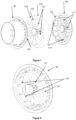
- FIG. 3 illustrates, schematically and in a non-limiting manner, an example of a stator grid 100 of an electric machine with a stator grid, a machine described at greater length in the patent applications FR 3 041 831 ( WO2017/050577 ) And FR 3 048 022 .
- the stator grid 100 comprises radial teeth 101 (also called “stator teeth”), and radial fluid passages 102 (for example, 12 radial passages and 12 radial teeth in the non-limiting example of the Figure 3 ). These radial passages 102 serve both as circulation galleries for the working fluid and both for mounting the coils.
- the stator teeth 101 extend from a central ring 103, continuous or discontinuous, for example with notches, to an external ring 104.
- the surfaces at the longitudinal ends of the internal 103 and external 104 rings as well as the surfaces at the longitudinal ends radial teeth 101 are planar and coplanar and thus form the surfaces 26.
- the radial passages are delimited by the two internal 103 and external 104 rings as well as by the radial teeth 101.
- FIG. 4 illustrates, schematically and in a non-limiting manner, a circumferential section of a stator grid assembly 100, of an aerodynamic appendage 85 according to one embodiment of the invention, upstream of the fluid inlet (for example of the air) in the stator grid 100, and an aerodynamic appendage 90 according to one embodiment of the invention, downstream of the fluid outlet of the stator grid 100.
- the first parts for guiding the flow of fluid circulation of the aerodynamic appendages 85 and 90 are not shown.
- the axis XX represents the longitudinal axis of the electric machine, common with the axis of the stator, the axis of the rotor and the axis of the aerodynamic appendages 85 and 90.
- This circumferential section makes it possible in particular to visualize the overall profile at the level of the assembly at the level of the stator teeth.
- This overall profile comprises a rounded profile 87, for example a semi-circle, on the aerodynamic appendage 85 upstream, the section, for example rectangular or of constant thickness, of the stator teeth 101 of the stator grid 100, and a tapered profile 92 , the thickness of which gradually decreases (ellipse of order 3 and more), on the aerodynamic appendage 90 downstream.
- the end of the tapered profile 92 can be rounded or pointed so as to improve the joining of flows coming from different adjacent circulation galleries.
- the tapered profile 92 on the aerodynamic appendage 90 located downstream has a variable longitudinal dimension (length) depending on the radial position.
- the aerodynamic appendage 85 upstream also has an ogive 80, placed in the center, coaxial with the stator and the stator grid 100.
- This ogive 80 extends from the stator grid 100, where it is substantially cylindrical and of greater radius at the rotor radius, in the longitudinal direction, in the direction opposite to the fluid circulation flow. Its end can be pointed, as on the figure 4 or rounded.
- the traffic flow which arrives first meets the ogive 80, by its tip or its rounded end.
- the circulation flow is then guided by the external wall of the warhead 80 towards the fluid circulation galleries, delimited by the radial teeth 101.
- the warhead 80 has, on the example of the figure 4 , openings 81 allowing the passage of fluid into the warhead 80 to cool the rotor and the air gap. This configuration is particularly relevant when the heat transfer fluid is free of aggressive chemical agents and solid particles which could damage the rotor and/or the air gap.
- the ogive 80 is preferably without openings 81. Thus, the fluid cannot enter the area of the air gap and thus the air gap and the rotor are protected.
- FIG 5 illustrates, schematically and in a non-limiting manner, an embodiment of the aerodynamic appendage 85 upstream (while the figure 4 is a circumferential cut at the level of the teeth) mounted on the stator grid 100.
- the aerodynamic appendage has, in addition to the aerodynamic profile 87 upstream of the teeth, a cylindrical wall 86 serving to guide the flow of fluid circulation at the interior of this wall.
- the fluid circulation flow thus passes completely in the conduit defined by the internal diameter of the cylindrical wall 86.
- This cylindrical wall 86 also makes it possible to isolate the windings from direct contact with the fluid.
- the aerodynamic appendage 85 can also include a central cone, coaxial with the stator.
- the warhead 80 may or may not include openings 81 for the passage of the fluid flow (air for example) towards the air gap and the rotor (not visible on the figure 5 ) and thus cool the rotor.
- the warhead is fixed with the aerodynamic profiles 87 covering the radial teeth 101. Thus, the warhead contributes to the rigidity of the assembly.
- an internal crown can be fitted as a replacement.
- the function of this internal crown is then to connect the aerodynamic profiles 87 covering the radial teeth 101 on their internal diameter in order to ensure the rigidity of the entire aerodynamic appendage 85.
- the aerodynamic appendage 85 has radial walls 89 covering the radial teeth, these radial walls 89 being located outside the space delimited by the cylindrical wall 86 and as an extension of the aerodynamic profile walls 87. Furthermore , the aerodynamic appendage 85 has radial walls 88 complementary to the radial walls 89 covering the radial teeth. These radial walls 88 serve to delimit the spaces of the coils (not shown) which surround the radial teeth. The radial walls 88 and 89 are held on their outer diameter by an outer ring 79. The outer ring bears, on one of these longitudinal ends, on the surface 26 of the stator grid 100. This end is therefore a flat surface to ensure optimal contact. The other end of this external ring 79 is also a flat surface, coplanar with the longitudinal end of the radial walls 89.
- the part of the aerodynamic appendage 85 delimited by the cylindrical wall 86 is subjected to a traffic flow which can thus damage it. It may be interesting to provide that this part of the aerodynamic appendage 85, comprising the cylindrical wall 86, the aerodynamic profile walls 87 covering the radial teeth 101, and the internal crown (not shown) or the ogive 80 when it is present, can be dismantled to be replaced if necessary.
- the part external to the cylindrical wall 86 may possibly be non-removable.
- the aerodynamic appendage 85 can be made up of two parts: a first removable part comprising the cylindrical wall 86, the internal crown or the ogive 80 when present and the aerodynamic profile walls 87 covering the radial teeth 101; a second non-removable part comprising the external crown 79 and the radial walls 88 and 89.
- connection areas have connection fillets or chamfers, so as to avoid any risk of disruption of fluid circulation.
- FIG. 6 illustrates, schematically and in a non-limiting manner, an embodiment of an aerodynamic appendage 90 downstream (while the Figure 4 is a circumferential cut at the level of the teeth) mounted on the stator grid 100.
- the aerodynamic appendage 90 has, in addition to the aerodynamic profile 92 downstream of the radial teeth 101, a cylindrical wall 93 serving to guide the flow of fluid leaving the fluid circulation galleries, delimited by the radial teeth 101, inside this cylindrical wall 93.
- the circulation flow leaving the fluid circulation galleries thus passes completely into the conduit defined by the internal diameter of the cylindrical wall 93 .
- the aerodynamic appendage 90 also includes an internal cylindrical wall 96 making it possible to ensure the connection and mechanical strength of the aerodynamic profile walls 92 between them.
- the aerodynamic appendage 90 has radial walls 95 covering the radial teeth, these radial walls 95 being located outside the space delimited by the cylindrical wall 93 and as an extension of the aerodynamic profile walls 92. Furthermore , the aerodynamic appendage 90 has radial walls 94 complementary to the radial walls 95 covering the radial teeth. These radial walls 94 serve to delimit the spaces of the coils (not shown) which surround the radial teeth.
- the aerodynamic appendage 90 comprises an external crown 97, for example cylindrical, the diameter of which is substantially equal to the diameter of the grid stator 100.
- the longitudinal ends of this external ring 97 are flat. On one side, it is in contact with the surface of the stator grid 100.
- the other flat surface end of the external ring 97 is coplanar with the longitudinal end of the radial walls 95.
- This ring makes it possible to maintain the assembly radial walls 92 and 95, in the extension of walls 92, and radial walls 94 between them.
- the mechanical strength of the aerodynamic appendage 90, as a whole, is ensured.
- the part of the aerodynamic appendage 90 delimited by the cylindrical wall 93 is subjected to a traffic flow which can thus damage it. It may be interesting to provide that this part of the aerodynamic appendage, comprising the cylindrical wall 93, and the aerodynamic profile 92 covering the radial teeth 101, and the internal cylindrical wall 96, can be dismantled to be replaced if necessary.
- the part external to the cylindrical wall 93 may possibly be non-removable.
- the aerodynamic appendage 90 can be made up of two parts: a first removable part comprising the cylindrical wall 93, the internal cylindrical wall 96 and the aerodynamic profile walls 92 covering the radial teeth 101; a second non-removable part comprising the external crown 97 and/or the radial walls 94 and 95.
- connection zones have connection fillets or chamfers, so as to avoid any risk of disruption of fluid circulation.
- FIG. 7 represents, schematically and in a non-limiting manner, an exploded view of an assembly, according to one embodiment of the invention, of the stator grid 100 and two aerodynamic appendages 85 and 90, located respectively upstream and downstream of the stator grid 100, in the direction of the fluid circulation flow.
- the two appendices correspond to those described in connection with the figures 5 and 6 .
- the mounting members 110 make it possible to mount the aerodynamic appendage 90 in the stator grid 100, these mounting members 110 engaging in the radial sails 102, in the external part, delimited by the external ring 104 and the stator teeth 101.
- the mounting member 110 comprises an extension of the radial walls 94, in the longitudinal direction extending from the outer end towards the inside, in the direction opposite to the direction of the flow, so that these radial walls 94 penetrate into the radial sails 102.
- the mounting member 110 also comprises a cylindrical wall portion 111, the radial wall 94 and the cylindrical wall 111 forming a section substantially in the shape of a "T", the cylindrical wall portion 111 extending the cylindrical wall 93, in meaning longitudinal, in the direction opposite to the flow, so as to penetrate the radial webs 102 of the stator grid 100.
- the junction between the radial wall 94 and the cylindrical wall 111, forming the T, is made at the level of the radial end internal of the radial wall 94 and approximately mid-circumferential length of the cylindrical wall portion 111.
- the number of mounting members 110 is equal to the number of radial sails 102 of the stator grid 100 (12 mounting members 110 in Figure 7 ).
- the mounting members 110 allow the positioning of the aerodynamic appendage 90 on the stator grid 100 and to avoid any relative rotation of these two parts, the relative rotation of these parts could hinder the flow of circulation of the fluid.
- the mounting members 110 are an integral part of the aerodynamic appendage 90.
- the mounting members 120 of the aerodynamic appendage 85 are substantially symmetrical to the mounting members 110 of the aerodynamic appendage 90 with respect to the median plane of the stator grid 100, a plane orthogonal to the longitudinal axis.
- FIG 8 represents, schematically and in a non-limiting manner, the aerodynamic appendage 90 of the figures 6 And 7 alone, unlike the Figure 6 which represents it mounted on the stator grid 100.
- the figure 8 makes it possible to visualize on the one hand the aerodynamic profile 92 and the external part 93 of the aerodynamic appendage, and on the other hand the mounting members 110 which penetrate into the stator grid 100 and which are not visible on the Figure 6 .
- FIG. 9 represents, schematically and in a non-limiting manner, the aerodynamic appendage 85 of the figures 5 And 7 alone, unlike the figure 5 which represents it mounted on the stator grid 100.
- the aerodynamic appendage 85 comprises aerodynamic profiles 87, an exterior part 86, an ogive 80 provided with openings 81.
- the mounting members 120 comprise radial walls 121 extending the radial walls 88, in the direction of the flow so as to penetrate the stator grid 100, the radial walls 121 being similar to the walls 94 of the mounting members 110, and portions of cylindrical walls 122, extending longitudinally the cylindrical wall 87 in the direction of the flow, so as to penetrate the stator grid, the portions of cylindrical walls 122 being similar to the portions of cylindrical walls 111 of the mounting members 110.
- mounting members 120 are similar to the mounting members 110, the radial walls 121 and portions of cylindrical walls 122 forming a section substantially in the shape of a "T", the junction between the radial wall 121 and the portion of cylindrical wall 122 is carried out at the level of the internal radial end of the radial wall 121 and at approximately mid-circumferential length of the cylindrical wall portion 122.
- the number of mounting members 120 is equal to the number of radial sails 102 of the stator grid 100 (12 mounting members 120 for example).
- the mounting members 120 allow the positioning of the aerodynamic appendage 85 on the stator grid 100 and to avoid any relative rotation of these two parts, the relative rotation of these parts could hinder the flow of circulation of the fluid.
- the mounting members 120 are an integral part of the aerodynamic appendage 85.
- FIG 10a represents, schematically and in a non-limiting manner, a section in a plane defined by the longitudinal axis XX of the electric machine (horizontal axis) and by a radial axis of a radial tooth 101 of an embodiment according to the invention .
- This figure shows the aerodynamic profile wall 87 of the upstream aerodynamic appendage 85, the stator tooth 101 and the aerodynamic profile wall 91 of the downstream aerodynamic appendage 90.
- each of these three parts has a constant length, along the longitudinal axis XX, depending on the radial position of the part considered.
- the longitudinal end surfaces of the airfoil wall 87 of the upstream aerodynamic appendage 85, of the stator tooth 101 and of the aerodynamic profile wall 91 of the downstream aerodynamic appendage 90 are all perpendicular to the XX axis.
- the aerodynamic profile wall 91 ends with a straight part, orthogonal to the axis XX and to the circulation flow of the fluid.
- FIG 10b represents, schematically and in a non-limiting manner, a section in a plane defined by the longitudinal axis XX of the electric machine (horizontal axis) and by a radial axis of a radial tooth 101, of an alternative embodiment according to invention.
- This figure shows the aerodynamic profile wall 87 of the upstream aerodynamic appendage 85, the stator tooth 101 and the aerodynamic profile wall 92 of the downstream aerodynamic appendage 90.
- the aerodynamic profile wall 87 of the appendage aerodynamic upstream 85 and the stator tooth 101 have a constant length depending on the radial position of the tooth and their longitudinal end surfaces are all perpendicular to the axis XX.
- the length of the aerodynamic profile wall 92 of the downstream aerodynamic appendage 90 depends on its radial position: the length is not constant but is variable as a function of the radial position
- the upstream longitudinal end surface according to the direction of the fluid circulation flow, the aerodynamic profile wall 92 is perpendicular to the axis XX.
- the longitudinal end surface downstream, in the direction of the fluid circulation flow, of the aerodynamic profile wall 92 is not perpendicular to the axis XX.
- the length of the aerodynamic profile wall 92 of the downstream aerodynamic appendage 90 decreases when its radial position increases.
- the length of the aerodynamic profile wall 92 of the downstream aerodynamic appendage 90 is greatest at its internal radius; the smallest length of the aerodynamic profile wall 92 of the downstream aerodynamic appendage 90 is located at its largest radius.
Description
La présente invention se rapporte à un dispositif de compression à assistance électrique d'un fluide de travail, tel qu'un fluide liquide ou un fluide gazeux.The present invention relates to an electrically assisted compression device for a working fluid, such as a liquid fluid or a gaseous fluid.
Elle concerne notamment un dispositif pour comprimer un fluide gazeux, ici de l'air, par un compresseur, seul ou associé à une turbine pour former un turbocompresseur, pour ensuite l'envoyer vers tous appareils et plus particulièrement à l'admission d'un moteur à combustion interne.It relates in particular to a device for compressing a gaseous fluid, here air, by a compressor, alone or associated with a turbine to form a turbocharger, to then send it to all devices and more particularly to the intake of a internal combustion engine.
En effet, comme cela est largement connu, la puissance délivrée par un moteur à combustion interne est dépendante de la quantité d'air introduite dans la chambre de combustion de ce moteur, quantité d'air qui est elle-même proportionnelle à la densité de cet air.Indeed, as is widely known, the power delivered by an internal combustion engine is dependent on the quantity of air introduced into the combustion chamber of this engine, a quantity of air which is itself proportional to the density of this air.
Ainsi, il est habituel d'augmenter cette quantité d'air au moyen d'une compression de l'air extérieur avant qu'il ne soit admis dans cette chambre de combustion lors d'un besoin d'une forte puissance. Cette opération, appelée suralimentation, peut être réalisée par tous moyens, tel qu'un compresseur seul entraîné électriquement par une machine électrique (compresseur électrifié), ou par un compresseur associé à une turbine et à une machine électrique pour former un turbocompresseur électrifié.Thus, it is usual to increase this quantity of air by means of compression of the outside air before it is admitted into this combustion chamber when high power is required. This operation, called supercharging, can be carried out by any means, such as a single compressor driven electrically by an electric machine (electrified compressor), or by a compressor associated with a turbine and an electric machine to form an electrified turbocharger.
Dans les deux cas précités, la machine électrique associée au compresseur peut être de plusieurs types.In the two aforementioned cases, the electrical machine associated with the compressor can be of several types.
L'un de ces types est une machine électrique à faible entrefer et bobinages proches du rotor qui permet un guidage optimal du flux magnétique et un rendement optimisé. Ce type de machine électrique présente l'avantage d'une certaine compacité, qui peut parfois devenir problématique pour son refroidissement et qui demande l'utilisation d'un système spécifique pour évacuer ses pertes thermiques.One of these types is an electric machine with a small air gap and windings close to the rotor which allows optimal guidance of the magnetic flux and optimized efficiency. This type of electric machine has the advantage of a certain compactness, which can sometimes become problematic for its cooling and which requires the use of a specific system to evacuate its thermal losses.
Afin de ne pas être intrusif sur l'entrée d'air du compresseur, ce type de machine électrique est classiquement positionné au dos du compresseur centrifuge dans le cas d'un compresseur électrifié, ou entre le compresseur et la turbine dans le cas d'un turbocompresseur électrifié, et cela malgré la présence d'un environnement thermique défavorable dans ce dernier cas, car proche de la turbine. Généralement, la liaison entre le compresseur, la turbine et la machine électrique est rigide. Ce type de machine peut aussi être positionné côté compresseur mais à une distance relativement éloignée de l'entrée d'air afin de ne pas perturber cette dernière. La liaison entre le compresseur et la machine est alors rigide ou réalisée à l'aide d'un accouplement mécanique ou magnétique.In order not to be intrusive on the air inlet of the compressor, this type of electric machine is conventionally positioned at the back of the centrifugal compressor in the case of an electrified compressor, or between the compressor and the turbine in the case of an electrified turbocharger, despite the presence of an unfavorable thermal environment in the latter case, because it is close to the turbine. Generally, the connection between the compressor, the turbine and the electrical machine is rigid. This type of machine can also be positioned on the compressor side but at a distance relatively far from the air inlet so as not to disturb the latter. The connection between the compressor and the machine is then rigid or made using a mechanical or magnetic coupling.
Ce type de systèmes est mieux décrit dans les brevets
Un autre type de machines est une machine électrique à fort entrefer (appelée machine à « Air Gap »), dont l'entrefer peut parfois mesurer plusieurs centimètres afin de laisser passer le fluide de travail dans cet entrefer permettant ainsi une intégration au plus proche des systèmes de compression, dans un environnement thermique nettement plus favorable.Another type of machine is an electric machine with a large air gap (called an “Air Gap” machine), whose air gap can sometimes measure several centimeters in order to allow the working fluid to pass through this air gap, thus allowing integration as close as possible to the compression systems, in a significantly more favorable thermal environment.
Cette disposition de machine électrique présente néanmoins le désavantage de perturber et limiter le passage du flux magnétique entre le rotor et le stator au travers du grand entrefer, ce qui contribue à limiter le rendement intrinsèque de la machine électrique ainsi que ses performances spécifiques (puissance massique et volumique).This arrangement of an electric machine nevertheless has the disadvantage of disrupting and limiting the passage of the magnetic flux between the rotor and the stator through the large air gap, which contributes to limiting the intrinsic efficiency of the electric machine as well as its specific performances (specific power and volume).
Ce type de machine électrique est notamment décrit dans les brevets
Enfin, un nouveau type de machine est apparu récemment. Il s'agit de la machine à grille statorique, qui est mieux décrit dans les demandes de brevets
Cette machine présente l'avantage d'offrir un meilleur compromis en termes de refroidissement et de performances électriques que les deux autres types de machines. En revanche, les faces planes des dents statoriques aux extrémités de la machine sont perpendiculaires à l'écoulement d'air et peuvent donc perturber le flux. L'impact sur l'écoulement de l'air engendre une baisse de performances du compresseur. Par ailleurs, modifier la forme des dents radiales pour améliorer l'écoulement d'air engendrerait un coût plus élevé de la machine. En effet, la réalisation du stator incluant ces dents étant un empilement de feuillards (plaques de fines épaisseurs) métalliques, pour modifier la forme des dents statoriques, il faudrait une géométrie spécifique sur chaque feuillard ou un assemblage particulier de feuillards, ce qui complexifierait à la fois la fabrication, impacterait négativement le coût du système final et la logistique, notamment pour repérer chacun des feuillards indépendamment.This machine has the advantage of offering a better compromise in terms of cooling and electrical performance than the other two types of machines. On the other hand, the flat faces of the stator teeth at the ends of the machine are perpendicular to the air flow and can therefore disrupt the flow. The impact on air flow causes a reduction in compressor performance. Furthermore, modifying the shape of the radial teeth to improve air flow would result in a higher cost of the machine. Indeed, the production of the stator including these teeth being a stack of metal strips (thin thickness plates), to modify the shape of the stator teeth, a specific geometry would be required on each strip or a particular assembly of strips, which would complicate both manufacturing and negatively impact the cost of the final system and logistics, in particular to identify each of the strips independently.
Pour remédier aux inconvénients précités, la présente invention concerne une machine électrique à grille statorique, comprenant un rotor et un stator qui comporte une multiplicité de passages radiaux disposés circonférentiellement le long du stator. Les passages radiaux sont délimités par des dents radiales et des générateurs de flux magnétique sont logés dans les passages radiaux. De plus, les passages radiaux comportent des galeries de circulation de fluide en regard des générateurs de flux magnétique. Pour améliorer le passage de fluide (par exemple de l'air) à travers la machine, la machine électrique comporte au moins un appendice aérodynamique, coaxial avec la machine électrique et agencé à une extrémité longitudinale de la machine électrique. Cet appendice aérodynamique comprend au moins deux parties : la première partie sert de guidage au fluide qui passe à travers les galeries de circulation ; la deuxième partie s'étend radialement le long des dents radiales et a, dans la direction axiale de la machine électrique, un profil aérodynamique pour guider le fluide.To remedy the aforementioned drawbacks, the present invention relates to an electric machine with a stator grid, comprising a rotor and a stator which comprises a multiplicity of radial passages arranged circumferentially along the stator. The radial passages are delimited by radial teeth and magnetic flux generators are housed in the radial passages. In addition, the radial passages include fluid circulation galleries opposite the magnetic flux generators. To improve the passage of fluid (for example air) through the machine, the electric machine comprises at least one aerodynamic appendage, coaxial with the electric machine and arranged at a longitudinal end of the electric machine. This aerodynamic appendage comprises at least two parts: the first part serves as a guide for the fluid which passes through the circulation galleries; the second part extends radially along the radial teeth and has, in the axial direction of the electric machine, an aerodynamic profile to guide the fluid.
L'invention concerne également un dispositif de compression équipé d'une telle machine électrique et un turbocompresseur électrifié avec ce type de machine.The invention also relates to a compression device equipped with such an electric machine and a turbocharger electrified with this type of machine.
Le dispositif selon l'invention concerne une machine électrique selon la revendication 1.The device according to the invention relates to an electrical machine according to claim 1.
De manière avantageuse, ledit appendice aérodynamique est fabriqué à partir d'un matériau à faible résistance thermique, de préférence un matériau polymère, préférentiellement un matériau polymère permettant la réalisation de formes complexes.Advantageously, said aerodynamic appendage is made from a material with low thermal resistance, preferably a polymer material, preferably a polymer material allowing the production of complex shapes.
De préférence, le fluide est de l'air.Preferably, the fluid is air.
De manière avantageuse, ledit appendice aérodynamique a un profil dissymétrique selon le plan médian dudit appendice aérodynamique.Advantageously, said aerodynamic appendage has an asymmetrical profile along the median plane of said aerodynamic appendage.
Selon une variante de l'invention, ledit appendice aérodynamique est réalisé par fabrication additive ou par moulage.According to a variant of the invention, said aerodynamic appendage is produced by additive manufacturing or by molding.
Selon un mode de réalisation de l'invention, ledit appendice aérodynamique est réalisé en au moins deux éléments, avec au moins un élément démontable.According to one embodiment of the invention, said aerodynamic appendage is made of at least two elements, with at least one removable element.
De manière avantageuse, le machine électrique comprend deux appendices aérodynamiques situés aux deux extrémités longitudinales de ladite machine électrique.Advantageously, the electric machine comprises two aerodynamic appendages located at the two longitudinal ends of said electric machine.
Préférentiellement, ladite deuxième partie dudit appendice aérodynamique, lorsque ledit appendice aérodynamique est positionné à l'extrémité longitudinale desdites dents radiales située à l'entrée dudit fluide dans lesdites galeries de circulation, a sensiblement un profil en demi-cercle dans une section orthogonale à la direction radiale desdites dents radiales.Preferably, said second part of said aerodynamic appendage, when said aerodynamic appendage is positioned at the longitudinal end of said radial teeth located at the entrance of said fluid into said circulation galleries, has substantially a semi-circle profile in a section orthogonal to the radial direction of said radial teeth.
De manière préférée, ledit appendice aérodynamique, positionné à l'extrémité longitudinale desdites dents radiales située à l'entrée dudit fluide dans lesdites galeries de circulation, comporte une ogive au centre, de préférence ladite ogive est de forme elliptique d'ordre au moins trois.Preferably, said aerodynamic appendage, positioned at the longitudinal end of said radial teeth located at the entrance of said fluid into said circulation galleries, comprises an ogive in the center, preferably said ogive is of elliptical shape of order at least three .
Avantageusement, ladite ogive comporte des ouvertures permettant un passage dudit fluide.Advantageously, said warhead comprises openings allowing said fluid to pass through.
Selon un mode de réalisation de l'invention, lesdites ouvertures de ladite ogive guident avantageusement le flux d'air dans l'entrefer pour minimiser les perturbations et la quantité d'air passant dans ledit entrefer.According to one embodiment of the invention, said openings of said warhead advantageously guide the air flow in the air gap to minimize disturbances and the quantity of air passing through said air gap.
De manière préférée, lesdites ouvertures de ladite ogive servent de protection contre des débris, la taille des ouvertures étant inférieure à l'épaisseur de l'entrefer.Preferably, said openings of said warhead serve as protection against debris, the size of the openings being less than the thickness of the air gap.
Selon une variante de l'invention, ladite deuxième partie dudit appendice aérodynamique, lorsque ledit appendice aérodynamique est positionné à l'extrémité longitudinale desdites dents radiales située à la sortie dudit fluide desdites galeries de circulation, est un profil dont l'épaisseur, dans une section perpendiculaire à la direction radiale desdites dents radiales, diminue longitudinalement, l'épaisseur la plus grande étant située au niveau de l'extrémité longitudinale desdites dents radiales.According to a variant of the invention, said second part of said aerodynamic appendage, when said aerodynamic appendage is positioned at the longitudinal end of said radial teeth located at the outlet of said fluid from said circulation galleries, is a profile whose thickness, in a section perpendicular to the radial direction of said radial teeth, decreases longitudinally, the greatest thickness being located at the longitudinal end of said radial teeth.
De manière préférée, ledit appendice aérodynamique positionné à l'extrémité longitudinale desdites dents radiales, située à la sortie dudit fluide desdites galeries de circulation, comporte une dimension longitudinale variable en fonction de sa position radiale, de préférence, la dimension longitudinale diminuant lorsque la position radiale augmente.Preferably, said aerodynamic appendage positioned at the longitudinal end of said radial teeth, located at the outlet of said fluid from said circulation galleries, has a variable longitudinal dimension as a function of its radial position, preferably, the longitudinal dimension decreasing when the position radial increases.
Selon une variante de l'invention, ledit appendice aérodynamique positionné à l'extrémité longitudinale desdites dents radiales, située en sortie dudit fluide desdites galeries de circulation, est équipé de volets aérodynamiques mobiles et d'un système de commande associé, lesdits volets aérodynamiques mobiles pour donner une direction avantageuse audit fluide en sortie de ladite machine électrique ou pour réguler le débit du fluide.According to a variant of the invention, said aerodynamic appendage positioned at the longitudinal end of said radial teeth, located at the outlet of said fluid from said circulation galleries, is equipped with movable aerodynamic flaps and an associated control system, said movable aerodynamic flaps to give an advantageous direction to said fluid at the outlet of said electrical machine or to regulate the flow of the fluid.
L'invention concerne également un dispositif de compression d'un fluide gazeux ou liquide comprenant un moyen de compression avec une admission dudit fluide à comprimer, une sortie dudit fluide comprimé, ledit moyen de compression dudit fluide étant porté par un arbre de compresseur et logé entre ladite admission et ladite sortie, et une machine électrique selon l'une des caractéristiques précédentes, ladite machine électrique étant positionnée en amont, selon le sens du flux de fluide, dudit moyen de compression.The invention also relates to a device for compressing a gaseous or liquid fluid comprising compression means with an inlet for said fluid to be compressed, an outlet for said compressed fluid, said means for compressing said fluid being carried by a compressor shaft and housed between said inlet and said outlet, and an electric machine according to one of the preceding characteristics, said electric machine being positioned upstream, in the direction of the fluid flow, of said compression means.
En outre, l'invention concerne aussi un dispositif de turbocompresseur électrifié comprenant un moyen de détente et un dispositif de compression, selon l'une des caractéristiques précédentes, ledit moyen de détente et ledit dispositif de compression étant fixés sur un même arbre de rotation, permettant une mise en rotation commune dudit moyen de détente et dudit dispositif de compression.Furthermore, the invention also relates to an electrified turbocharger device comprising an expansion means and a compression device, according to one of the preceding characteristics, said expansion means and said compression device being fixed on the same rotation shaft, allowing common rotation of said expansion means and said compression device.
D'autres caractéristiques et avantages du dispositif selon l'invention, apparaîtront à la lecture de la description ci-après d'exemples non limitatifs de réalisations, en se référant aux figures annexées et décrites ci-après.
- La
figure 1 illustre schématiquement l'agencement d'un dispositif de compression électrifié selon un mode de réalisation de l'invention. - La
figure 2 illustre schématiquement l'agencement d'un turbocompresseur électrifié selon un mode de réalisation de l'invention. - La
figure 3 illustre une vue en perspective de la grille statorique. - La
figure 4 illustre une coupe circonférentielle au niveau des dents statoriques d'une vue en perspective d'un mode de réalisation d'un assemblage, selon l'invention, de la grille statorique équipée de deux appendices aérodynamiques. - La
figure 5 illustre une vue en perspective d'un assemblage, selon un mode de réalisation de l'invention, de la grille statorique et de l'appendice aérodynamique en amont, au niveau de l'entrée du fluide dans la grille statorique. - La
figure 6 illustre une vue en perspective d'un assemblage, selon un mode de réalisation de l'invention, de la grille statorique et de l'appendice aérodynamique en aval, au niveau de la sortie de fluide de la grille statorique. - La
figure 7 représente une vue éclatée d'un mode de réalisation d'un assemblage, selon l'invention, de l'appendice aérodynamique en amont, au niveau de l'entrée du fluide dans la grille statorique, de la grille statorique elle-même et de l'appendice aérodynamique en aval, au niveau de la sortie de fluide de la grille statorique. - La
figure 8 représente une vue en perspective d'une variante de l'appendice aérodynamique situé en aval de la grille statorique, au niveau de la sortie de fluide de la grille statorique, selon un mode de réalisation de l'invention. - La
figure 9 représente une vue en perspective d'une variante de l'appendice aérodynamique situé en amont de la grille statorique, au niveau de l'entrée de fluide de la grille statorique, selon un mode de réalisation de l'invention. - La
figure 10a représente une variante d'un mode de réalisation selon l'invention, de coupe longitudinale au niveau des dents statoriques, avec un appendice aérodynamique, en sortie de la grille statorique, de longueur constante en fonction de la position radiale. - La
figure 10b représente une variante d'un mode de réalisation selon l'invention, de coupe longitudinale au niveau des dents statoriques, avec un appendice aérodynamique, en sortie de la grille statorique, de longueur variable en fonction de la position radiale.
- There
figure 1 schematically illustrates the arrangement of an electrified compression device according to one embodiment of the invention. - There
figure 2 schematically illustrates the arrangement of an electrified turbocharger according to one embodiment of the invention. - There
Figure 3 illustrates a perspective view of the stator grid. - There
figure 4 illustrates a circumferential section at the level of the stator teeth of a perspective view of an embodiment of an assembly, according to the invention, of the stator grid equipped with two aerodynamic appendages. - There
figure 5 illustrates a perspective view of an assembly, according to one embodiment of the invention, of the stator grid and the aerodynamic appendage upstream, at the level of the fluid entry into the stator grid. - There
Figure 6 illustrates a perspective view of an assembly, according to one embodiment of the invention, of the stator grid and the aerodynamic appendage downstream, at the level of the fluid outlet of the stator grid. - There
Figure 7 represents an exploded view of an embodiment of an assembly, according to the invention, of the aerodynamic appendage upstream, at the level of the fluid entry into the stator grid, of the stator grid itself and of the aerodynamic appendage downstream, at the level of the fluid outlet of the stator grid. - There
figure 8 represents a perspective view of a variant of the aerodynamic appendage located downstream of the stator grid, at the level of the fluid outlet of the stator grid, according to one embodiment of the invention. - There
Figure 9 represents a perspective view of a variant of the aerodynamic appendage located upstream of the stator grid, at the level of the fluid inlet of the stator grid, according to one embodiment of the invention. - There
figure 10a represents a variant of an embodiment according to the invention, of longitudinal section at the level of the stator teeth, with an aerodynamic appendage, at the outlet of the stator grid, of constant length depending on the radial position. - There
figure 10b represents a variant of an embodiment according to the invention, of longitudinal section at the level of the stator teeth, with an aerodynamic appendage, at the outlet of the stator grid, of variable length depending on the radial position.
L'invention concerne une machine électrique comprenant un rotor et un stator. Le stator comporte une multiplicité de passages radiaux disposés circonférentiellement le long du stator. Les passages radiaux sont délimités par des dents radiales et des générateurs de flux magnétique sont logés dans les passages radiaux. Les générateurs de flux magnétiques sont par exemple, des bobines. De plus, les passages radiaux comportent des galeries de circulation de fluide en regard des générateurs de flux magnétique.The invention relates to an electric machine comprising a rotor and a stator. The stator has a multiplicity of radial passages arranged circumferentially along the stator. The radial passages are delimited by radial teeth and magnetic flux generators are housed in the radial passages. Magnetic flux generators are, for example, coils. In addition, the radial passages include fluid circulation galleries opposite the magnetic flux generators.
Par ailleurs, la machine électrique comporte au moins un appendice aérodynamique, coaxial avec ladite machine électrique et agencé à une extrémité longitudinale de ladite machine électrique. Cet appendice aérodynamique comprend au moins une première partie de guidage de fluide passant à travers les galeries de circulation et au moins une deuxième partie s'étendant radialement le long d'au moins une desdites dents radiales et ayant, dans la direction axiale de ladite machine électrique, un profil aérodynamique pour guider le fluide. L'utilisation de cet appendice aérodynamique permet de mieux canaliser le flux de fluide, grâce à la première partie de guidage de l'appendice aérodynamique, d'une part et d'éviter les perturbations de l'écoulement aux passages des dents statoriques, grâce à la deuxième partie profilée de l'appendice aérodynamique, d'autre part.Furthermore, the electric machine comprises at least one aerodynamic appendage, coaxial with said electric machine and arranged at a longitudinal end of said electric machine. This aerodynamic appendage comprises at least a first part for guiding fluid passing through the circulation galleries and at least a second part extending radially along at least one of said radial teeth and having, in the axial direction of said machine electric, an aerodynamic profile to guide the fluid. The use of this aerodynamic appendage makes it possible to better channel the flow of fluid, thanks to the first guiding part of the aerodynamic appendage, on the one hand and to avoid disturbances in the flow at the passages of the stator teeth, thanks to to the second profiled part of the aerodynamic appendage, on the other hand.
Cette machine est, uniquement à titre d'exemple dans la suite de la description, une machine synchrone à une paire de pôles.This machine is, solely by way of example in the remainder of the description, a synchronous machine with a pair of poles.
Cela n'écarte en aucune façon toute autre machine électrique, comme des machines synchrones avec plus d'une paire de pôles, des machines asynchrones à rotor bobiné ou à cage d'écureuil et les machines à reluctance.This in no way precludes any other electrical machines, such as synchronous machines with more than one pair of poles, asynchronous machines with wound rotor or squirrel cage, and reluctance machines.
Selon un mode de réalisation, l'appendice aérodynamique peut être fabriqué à partir d'un matériau à faible résistance thermique, de préférence un matériau polymère. Ainsi, le refroidissement de la grille statorique est amélioré, la faible résistance thermique impliquant un matériau de bonne conductivité thermique. De préférence, le matériau polymère peut être compatible avec une machine de fabrication additive ou avec un procédé de moulage, pour réaliser des formes complexes,According to one embodiment, the aerodynamic appendage can be manufactured from a material with low thermal resistance, preferably a polymer material. Thus, the cooling of the stator grid is improved, the low thermal resistance implying a material of good thermal conductivity. Preferably, the polymer material can be compatible with an additive manufacturing machine or with a molding process, to produce complex shapes,
Selon une autre variante de l'invention, l'appendice aérodynamique peut avoir un profil dissymétrique selon son plan médian. Cette particularité a l'avantage de modifier la direction de l'écoulement par exemple, et peut présenter un réel intérêt par exemple pour orienter le flux en sortie, vers un prochain accessoire, comme un compresseur par exemple afin d'améliorer ses performances.According to another variant of the invention, the aerodynamic appendage may have an asymmetrical profile along its median plane. This particularity has the advantage of modifying the direction of the flow for example, and can be of real interest for example to direct the output flow, towards a next accessory, such as a compressor for example in order to improve its performance.
Préférentiellement, l'appendice aérodynamique peut être réalisé par fabrication additive ou par moulage. De cette manière, le coût de l'appendice aérodynamique peut être réduit. Le moulage est particulièrement intéressant pour des pièces réalisées en série car cette technique de fabrication permet une réalisation rapide et un coût réduit. La fabrication additive permet la réalisation de pièces complexes, notamment de pièces non réalisables par moulage.Preferably, the aerodynamic appendage can be produced by additive manufacturing or by molding. In this way, the cost of the aerodynamic appendage can be reduced. Molding is particularly interesting for parts produced in series because this manufacturing technique allows rapid production and reduced cost. Additive manufacturing allows the production of complex parts, particularly parts that cannot be produced by molding.
Selon une variante de réalisation de l'invention, l'appendice aérodynamique peut être réalisé en, au moins, deux éléments, avec au moins un élément démontable. En effet, le flux de fluide peut être chargé d'éléments fluides ou solides agressifs qui peuvent endommager l'appendice aérodynamique. Rendre démontable au moins la partie de l'appendice en contact avec le fluide, potentiellement chargé, permet de pouvoir le remplacer facilement et conserver les performances, électriques et thermiques, de la machine électrique tout en augmentant sa durée de vie. Une partie de l'appendice aérodynamique n'étant pas en contact avec le fluide, celle-ci peut être conservée sur toute la durée de vie de la machine électrique.According to a variant embodiment of the invention, the aerodynamic appendage can be made in at least two elements, with at least one removable element. Indeed, the fluid flow can be loaded with aggressive fluid or solid elements which can damage the aerodynamic appendage. Making at least the part of the appendix in contact with the fluid, potentially charged, removable allows it to be replaced easily and to maintain the electrical and thermal performance of the electrical machine while increasing its lifespan. As part of the aerodynamic appendage is not in contact with the fluid, it can be retained over the entire life of the electric machine.
De préférence, la machine électrique peut comprendre deux appendices aérodynamiques situés aux deux extrémités longitudinales de la machine électrique. Ainsi, l'écoulement de fluide est canalisé à l'entrée et à la sortie du fluide dans la grille statorique, ce qui permet d'améliorer les performances et le refroidissement de la machine électrique, de limiter les pertes de charge et d'optimiser les performances d'un composant qui se trouverait en sortie, comme un compresseur par exemple.Preferably, the electric machine may comprise two aerodynamic appendages located at the two longitudinal ends of the electric machine. Thus, the fluid flow is channeled at the entry and exit of the fluid in the stator grid, which makes it possible to improve the performance and cooling of the electric machine, to limit load losses and to optimize the performance of a component which would be at the output, such as a compressor for example.
Selon une variante de l'invention, la deuxième partie de l'appendice aérodynamique, lorsqu'il est positionné à l'extrémité longitudinale des dents radiales située à l'entrée du fluide dans les galeries de circulation, peut avoir sensiblement un profil en demi-cercle dans une section orthogonale à la direction radiale desdites dents radiales. Ce profil aérodynamique de section en demi-cercle permet de limiter le risque de perturbations de l'écoulement au niveau de l'entrée du fluide dans la grille statorique.According to a variant of the invention, the second part of the aerodynamic appendage, when positioned at the longitudinal end of the radial teeth located at the entry of the fluid into the circulation galleries, can have substantially a half-shaped profile. -circle in a section orthogonal to the radial direction of said radial teeth. This aerodynamic profile with a semi-circle section makes it possible to limit the risk of disturbances to the flow at the level of the fluid entry into the stator grid.
Selon une variante de l'invention, l'appendice aérodynamique, positionné à l'extrémité longitudinale des dents radiales située à l'entrée du fluide dans les galeries de circulation, peut comporter une ogive au centre. L'ogive a une forme de révolution avec un diamètre croissant dans la direction longitudinale et dans le sens du flux de circulation du fluide, de manière à diriger le flux progressivement. De préférence, l'ogive est de forme elliptique d'ordre au moins trois. L'ogive permet d'orienter le flux dans les galeries de circulation, en limitant au maximum les perturbations de l'écoulement dans cette zone. Cette caractéristique est particulièrement vérifiée lorsque l'ogive est de forme elliptique d'ordre au moins trois, dans la direction longitudinale. L'ogive a également l'avantage de protéger le rotor et l'entrefer du flux de circulation de fluide et des éventuels éléments solides qui pourraient dégrader le rotor ou l'entrefer et ainsi dégrader les performances de la machine électrique. L'ogive est coaxiale du rotor, de l'arbre de rotation et/ou du stator de la machine électrique. Préférentiellement, l'ogive, au niveau de son extrémité la plus proche de la grille statorique, a une forme extérieure sensiblement cylindrique et de préférence avec un diamètre supérieur à celui du diamètre du rotor.According to a variant of the invention, the aerodynamic appendage, positioned at the longitudinal end of the radial teeth located at the entry of the fluid into the circulation galleries, can include a warhead in the center. The warhead has a shape of revolution with an increasing diameter in the longitudinal direction and in the direction of the flow of circulation of the fluid, so as to direct the flow gradually. Preferably, the warhead is of elliptical shape of order at least three. The ogive makes it possible to direct the flow in the circulation galleries, limiting the disruption of the flow in this area as much as possible. This characteristic is particularly verified when the warhead is of elliptical shape of order at least three, in the longitudinal direction. The warhead also has the advantage of protecting the rotor and the air gap from the flow of fluid and any solid elements which could damage the rotor or the air gap and thus degrade the performance of the electrical machine. The warhead is coaxial with the rotor, the rotation shaft and/or the stator of the electric machine. Preferably, the warhead, at its end closest to the stator grid, has a substantially cylindrical exterior shape and preferably with a diameter greater than that of the diameter of the rotor.
Selon un variante de ce mode de réalisation, lorsque l'appendice aérodynamique comporte une ogive, l'ogive peut comporter des ouvertures permettant un passage de fluide dans l'entrefer. Préférentiellement, ce mode de réalisation peut être utilisé lorsque le fluide caloporteur ne comporte pas d'éléments agressifs chimiques ou mécaniques (particules solides par exemple) risquant de détériorer le rotor et/ou l'entrefer. Permettre un passage de fluide dans l'entrefer, par l'utilisation d'ouvertures dans l'ogive permet de mieux refroidir le rotor, et donc de maintenir les performances de la machine électrique, tout en minimisant les pertes de charge de l'écoulement complet. De préférence, ces ouvertures ont une taille inférieure à l'épaisseur de l'entrefer, de manière à empêcher à des débris de passer dans l'entrefer et de le boucher.According to a variant of this embodiment, when the aerodynamic appendage comprises a warhead, the warhead may include openings allowing the passage of fluid in the air gap. Preferably, this embodiment can be used when the heat transfer fluid does not contain aggressive chemical or mechanical elements (solid particles for example) risking damaging the rotor and/or the air gap. Allowing fluid to pass through the air gap, through the use of openings in the ogive, allows the rotor to be better cooled, and therefore maintain the performance of the electrical machine, while minimizing flow pressure losses. complete. Preferably, these openings have a size less than the thickness of the air gap, so as to prevent debris from passing into the air gap and blocking it.
De manière alternative, l'appendice aérodynamique, positionné à l'extrémité longitudinale des dents radiales située à l'entrée du fluide dans les galeries de circulation, peut comporter une couronne interne sous la forme d'un anneau interne ou d'un disque plein, en lieu et place de l'ogive décrite précédemment. Cette couronne interne permet de relier les parois de profil aérodynamique entre elles et ainsi de renforcer mécaniquement l'appendice aérodynamique.Alternatively, the aerodynamic appendage, positioned at the longitudinal end of the radial teeth located at the entry of the fluid into the circulation galleries, may include an internal crown in the form of an internal ring or a solid disc , in place of the warhead described previously. This internal crown makes it possible to connect the aerodynamic profile walls together and thus mechanically reinforce the aerodynamic appendage.
L'utilisation d'un disque plein pour la couronne interne permet d'éviter au fluide de pénétrer dans l'entrefer. Si ce fluide est chargé d'agents chimiques ou mécaniques (particules solides par exemple) agressifs, le disque plein permet de protéger le rotor et l'entrefer de ces agents.Using a solid disc for the internal ring prevents fluid from penetrating the air gap. If this fluid is loaded with aggressive chemical or mechanical agents (solid particles for example), the solid disc helps protect the rotor and the air gap from these agents.
Au contraire, l'utilisation d'un anneau interne pour la couronne interne, l'anneau interne étant caractérisé par un diamètre externe et un diamètre interne non nul, permet au fluide de pouvoir pénétrer dans l'entrefer. Cette particularité permet d'améliorer le refroidissement du rotor et donc d'améliorer les performances de la machine électrique. Cela est particulièrement intéressant lorsque le fluide est exempt d'agents chimiques ou mécaniques (particules solides par exemple) agressifs.On the contrary, the use of an internal ring for the internal ring, the internal ring being characterized by an external diameter and a non-zero internal diameter, allows the fluid to be able to penetrate into the air gap. This feature makes it possible to improve the cooling of the rotor and therefore improve the performance of the electric machine. This is particularly interesting when the fluid is free of aggressive chemical or mechanical agents (solid particles for example).
Selon une autre variante de l'invention, la deuxième partie de l'appendice aérodynamique, lorsqu'il est positionné à l'extrémité longitudinale des dents radiales situées à la sortie du fluide des galeries de circulation, peut être un profil dont l'épaisseur, dans une section perpendiculaire à la direction radiale des dents radiales, peut diminuer longitudinalement, l'épaisseur la plus grande étant située au niveau de l'extrémité longitudinale des dents radiales. Ce profil aérodynamique de section effilée dont l'épaisseur diminue progressivement permet de limiter le risque de perturbations de l'écoulement en sortie du fluide de la grille statorique. Ce profil peut notamment se terminer par une pointe afin de recoller les écoulements provenant de deux galeries de circulation adjacentes, en limitant au maximum les perturbations et les pertes de charge.According to another variant of the invention, the second part of the aerodynamic appendage, when positioned at the longitudinal end of the radial teeth located at the outlet of the fluid from the circulation galleries, can be a profile whose thickness , in a section perpendicular to the radial direction of the radial teeth, can decrease longitudinally, the greatest thickness being located at the level of the longitudinal end of the radial teeth. This aerodynamic profile with a tapered section whose thickness gradually decreases makes it possible to limit the risk of disturbances in the flow at the outlet of the fluid from the stator grid. This profile can in particular end with a point in order to join the flows coming from two adjacent circulation galleries, while limiting disturbances and pressure losses as much as possible.
De manière préférée, l'appendice aérodynamique positionné à l'extrémité longitudinale des dents radiales, situé à la sortie du fluide des galeries de circulation, peut comporter une dimension longitudinale variable en fonction de sa position radiale. De préférence, la dimension longitudinale peut diminuer lorsque la position radiale augmente. Ainsi, l'aérodynamisme en sortie des dents radiales est améliorée car le flux peut se recoller en limitant les perturbations aérodynamiques.Preferably, the aerodynamic appendage positioned at the longitudinal end of the radial teeth, located at the outlet of the fluid from the circulation galleries, can have a variable longitudinal dimension depending on its radial position. Preferably, the longitudinal dimension can decrease as the radial position increases. Thus, the aerodynamics at the exit of the radial teeth are improved because the flow can recover while limiting aerodynamic disturbances.
Selon une variante de l'invention, l'appendice aérodynamique positionné à l'extrémité longitudinale des dents radiales, situé en sortie du fluide des galeries de circulation, peut être équipé de volets mobiles et d'un système de commande associé, les volets mobiles permettant de modifier le profil aérodynamique en sortie de la machine électrique. Cette fonction permet d'optimiser la direction du flux de fluide, en fonction de la machine électrique, du compresseur et des performances attendues au système global.According to a variant of the invention, the aerodynamic appendage positioned at the longitudinal end of the radial teeth, located at the outlet of the fluid from the circulation galleries, can be equipped with movable flaps and an associated control system, the movable flaps making it possible to modify the aerodynamic profile at the outlet of the electric machine. This function makes it possible to optimize the direction of the fluid flow, depending on the electrical machine, the compressor and the expected performance of the overall system.
L'invention concerne également un dispositif de compression d'un fluide gazeux ou liquide comprenant un moyen de compression (compresseur par exemple) avec une admission du fluide à comprimer, une sortie du fluide comprimé. Le moyen de compression du fluide est porté par un arbre de compresseur et logé entre l'admission et la sortie. Le dispositif comporte également une machine électrique selon l'un des modes de réalisation décrits précédemment, la machine électrique étant positionnée en amont, selon le sens du flux de fluide, du moyen de compression. L'utilisation de la machine électrique décrite précédemment pour un compresseur électrifié permet d'améliorer les performances de refroidissement de la machine électrique, augmentant ainsi ses performances et sa durée de vie, tout en offrant au compresseur, un flux de circulation du fluide minimisant les pertes de charge au sein de la machine électrique, et limitant les perturbations aérodynamiques à l'entrée du compresseur, permettant d'améliorer les performances de compression.The invention also relates to a device for compressing a gaseous or liquid fluid comprising a compression means (compressor for example) with an inlet of the fluid to be compressed, an outlet of the compressed fluid. The fluid compression means is carried by a compressor shaft and housed between the inlet and outlet. The device also comprises an electric machine according to one of the embodiments described above, the electric machine being positioned upstream, in the direction of the fluid flow, of the compression means. The use of the electric machine described above for an electrified compressor makes it possible to improve the cooling performance of the electric machine, thus increasing its performance and its lifespan, while providing the compressor with a fluid circulation flow minimizing the load losses within the electrical machine, and limiting aerodynamic disturbances at the compressor inlet, making it possible to improve compression performance.
L'invention concerne également un dispositif de turbocompresseur électrifié comprenant un moyen de détente (turbine par exemple) et un dispositif de compression électrifié, tel que défini précédemment. Le moyen de détente et le dispositif de compression sont fixés sur un même arbre de rotation, permettant une mise en rotation commune du moyen de détente et du dispositif de compression. En utilisant le dispositif de compression électrifié défini précédemment, les performances de compression sont améliorées et donc les performances du turbocompresseur seront également supérieures, le débit de fluide à l'entrée de la turbine étant augmenté par l'accroissement de performance du compresseur.The invention also relates to an electrified turbocharger device comprising an expansion means (turbine for example) and an electrified compression device, as defined above. The expansion means and the compression device are fixed on the same rotation shaft, allowing common rotation of the expansion means and the compression device. By using the electrified compression device defined previously, the compression performance is improved and therefore the performance of the turbocharger will also be higher, the flow rate of fluid at the inlet of the turbine being increased by the increase in performance of the compressor.
Par ailleurs, le compresseur peut être équipé d'une recirculation, appelée « ported shroud », qui permet à une partie des gaz comprimés par le compresseur d'être rejetée en amont du compresseur. Cette recirculation d'une partie des gaz comprimés permet d'éviter le phénomène de pompage qui peut se produire dans certaines conditions de fonctionnement (faible débit, forte différence de pression entre l'entrée et la sortie du compresseur) et qui peut entraîner une inversion instationnaire de la direction du flux dans le compresseur. Lorsqu'il se produit, ce pompage peut entraîner des dommages très importants au niveau du compresseur.Furthermore, the compressor can be equipped with recirculation, called "ported shroud", which allows part of the gases compressed by the compressor to be rejected upstream of the compressor. This recirculation of part of the compressed gases makes it possible to avoid the pumping phenomenon which can occur under certain operating conditions (low flow rate, large pressure difference between the inlet and outlet of the compressor) and which can lead to inversion. unsteady flow direction in the compressor. When it occurs, this pumping can cause very significant damage to the compressor.
Dans le cas où le compresseur est équipé de « ported shroud », un bord de fuite pour lequel la longueur de la paroi de profil aérodynamique 92 de l'appendice aérodynamique aval 90 diminue lorsque sa position radiale augmente est particulièrement avantageux. En effet, la longueur réduite au niveau du diamètre extérieur permet de diminuer le sillage sur le rayon externe et empêche ainsi un fonctionnement intempestif du ported shroud lorsque cela n'est pas nécessaire, permettant ainsi d'améliorer le rendement du compresseur. Conserver une longueur plus grande sur le diamètre interne permet au contraire d'éviter une perturbation du sillage au niveau de l'entrée du compresseur.In the case where the compressor is equipped with "ported shroud", a trailing edge for which the length of the
La
Ce dispositif est en particulier utilisé en tant que compresseur d'un fluide contrôlé par une machine électrique, et sera dénommé dans la suite en tant que compresseur électrifié.This device is in particular used as a compressor of a fluid controlled by an electric machine, and will be referred to below as an electrified compressor.
Le compresseur 11, ici par exemple de type compresseur centrifuge à roue à ailettes, comprend un carter 12 avec une admission 14 de fluide gazeux, comme de l'air ou un mélange d'air (pouvant contenir des gaz d'échappement), et une sortie 16 de fluide comprimé.The
Ce carter 12 loge un moyen de compression sous la forme d'une roue de compresseur 18 placée entre l'admission et la sortie et qui est soumise à un mouvement de rotation sur un arbre 20.This
Cet arbre 20 est lié en rotation avec un rotor 22 d'une machine électrique 24 placée en regard de l'admission 14 et en amont de cette admission en considérant la veine de fluide gazeux Fa qui circule de la gauche vers la droite de la
Comme décrit ci-après, la machine électrique, qui est utilisée en tant que machine motrice, a la particularité d'avoir une configuration telle que le fluide gazeux traverse le stator de cette machine pour être amené à l'admission 14 du compresseur.As described below, the electric machine, which is used as a driving machine, has the particularity of having a configuration such that the gaseous fluid passes through the stator of this machine to be brought to the
Dans l'exemple de la
L'exemple de la
L'ensemble ainsi formé est plus connu sous le terme de turbocompresseur 46.The assembly thus formed is better known under the
Comme pour la
Le dispositif de détente 44 comprend une turbine avec un carter 50 portant une entrée 52 de fluide (de l'air chaud comprimé par exemple ou comme les gaz d'échappement d'un moteur à combustion interne), et une sortie 54 de fluide détendu. Une roue de turbine 56, ici une roue à ailettes, est placée dans le carter 50 entre l'entrée et la sortie en étant portée par un arbre 58 de roue de turbine. Cet arbre 58 est lié en rotation avec l'ensemble formé par le rotor 22 de la machine électrique et l'arbre 20 de roue de compresseur.The expansion device 44 comprises a turbine with a
Le rotor 22, l'arbre de roue de compresseur 20 et l'arbre 58 de roue de turbine forment ainsi un ensemble monobloc qui est supporté par un palier 40a.The
Pour cet exemple de la
Il est également possible d'entraîner le compresseur par la turbine et par la machine électrique utilisée en tant que moteur électrique, ce qui permet d'accroître les performances dynamique et statique du turbocompresseur, notamment d'augmenter le taux de compression pour un taux de détente donné et favoriser l'activation et la montée en régime du compresseur (réduction du temps de réponse du turbocompresseur).It is also possible to drive the compressor by the turbine and by the electric machine used as an electric motor, which makes it possible to increase the dynamic and static performance of the turbocharger, in particular to increase the compression ratio for a rate of given relaxation and promote the activation and increase in speed of the compressor (reduction of the response time of the turbocharger).
Il est à noter qu'un traitement surfacique du stator et du rotor rend cette machine compatible avec l'admission d'un fluide corrosif, tel que les gaz d'échappement d'un moteur qui peuvent être mélangés avec de l'air.It should be noted that a surface treatment of the stator and rotor makes this machine compatible with the admission of a corrosive fluid, such as the exhaust gases of an engine which can be mixed with air.
De plus, ce type de machine peut notamment être intégré assez simplement sur un système de turbocompresseur existant sans nécessiter de modifications profondes du système original.In addition, this type of machine can be integrated quite simply into an existing turbocharger system without requiring major modifications to the original system.
Dans ce type d'architecture, le rotor de la machine électrique peut notamment assurer la fonction de l'écrou de serrage côté compresseur.In this type of architecture, the rotor of the electric machine can in particular perform the function of the clamping nut on the compressor side.
La
La
L'appendice aérodynamique 85 en amont dispose également d'une ogive 80, placée au centre, coaxiale du stator et de la grille statorique 100. Cette ogive 80 s'étend depuis la grille statorique 100, où elle est sensiblement cylindrique et de rayon supérieur au rayon du rotor, dans la direction longitudinale, dans le sens opposé au flux de circulation du fluide. Son extrémité peut être pointue, comme sur la
L'ogive 80 dispose, sur l'exemple de la
Lorsque le fluide caloporteur est chargé d'agents chimiques agressifs ou de particules solides qui peuvent endommager le rotor ou l'entrefer, l'ogive 80 est préférentiellement sans ouvertures 81. Ainsi, le fluide ne peut pas entrer dans la zone de l'entrefer et ainsi l'entrefer et le rotor sont protégés.When the heat transfer fluid is loaded with aggressive chemical agents or solid particles which can damage the rotor or the air gap, the
La
L'appendice aérodynamique 85 peut également comprendre une ogive centrale, coaxiale du stator. L'ogive 80 peut, ou non, comprendre des ouvertures 81 pour le passage du flux de fluide (air par exemple) vers l'entrefer et le rotor (non visible sur la
Lorsqu'aucune ogive n'est utilisée, une couronne interne peut être mise en remplacement. La fonction de cette couronne interne est alors de relier les profils aérodynamiques 87 recouvrant les dents radiales 101 sur leur diamètre interne afin d'assurer la rigidité de l'ensemble de l'appendice aérodynamique 85.When no warhead is used, an internal crown can be fitted as a replacement. The function of this internal crown is then to connect the
A l'extérieur de cette paroi cylindrique 86, aucun flux ne circule. En revanche, l'appendice aérodynamique 85 dispose de parois radiales 89 recouvrant les dents radiales, ces parois radiales 89 étant situées à l'extérieur de l'espace délimité par la paroi cylindrique 86 et en prolongement des parois de profil aérodynamique 87. De plus, l'appendice aérodynamique 85 dispose de parois radiales 88 complémentaires aux parois radiales 89 recouvrant les dents radiales. Ces parois radiales 88 servent à délimiter les espaces des bobines (non représentées) qui entourent les dents radiales. Les parois radiales 88 et 89 sont maintenues sur leur diamètre extérieur par une couronne externe 79. La couronne externe vient en appui, sur une de ces extrémités longitudinales sur la surface 26 de la grille statorique 100. Cette extrémité est donc une surface plane pour assurer un contact optimal. L'autre extrémité de cette couronne externe 79 est également une surface plane, coplanaire de l'extrémité longitudinale des parois radiales 89.Outside of this
La partie de l'appendice aérodynamique 85 délimitée par la paroi cylindrique 86 est soumise à un flux de circulation qui peut ainsi l'endommager. Il peut être intéressant de prévoir que cette partie de l'appendice aérodynamique 85, comprenant la paroi cylindrique 86, les parois de profil aérodynamique 87 recouvrant les dents radiales 101, et la couronne interne (non représentée) ou l'ogive 80 lorsqu'elle est présente, puisse être démontable pour être remplacée si besoin.The part of the
La partie extérieure à la paroi cylindrique 86, peut éventuellement être non démontable. Ainsi, l'appendice aérodynamique 85 peut être constituée de deux parties : une première partie démontable comprenant la paroi cylindrique 86, la couronne interne ou l'ogive 80 lorsqu'elle est présente et les parois de profil aérodynamique 87 recouvrant les dents radiales 101 ; une seconde partie non démontable comprenant la couronne externe 79 et les parois radiales 88 et 89.The part external to the
Les zones de raccordements géométriques disposent de congé de raccordement ou de chanfreins, de manière à éviter tout risque de perturbations de circulation de fluide.The geometric connection areas have connection fillets or chamfers, so as to avoid any risk of disruption of fluid circulation.
La
L'appendice aérodynamique 90 comprend également une paroi cylindrique interne 96 permettant d'assurer la liaison et la tenue mécanique des parois de profil aérodynamique 92 entre-elles.The
A l'extérieur de cette paroi cylindrique 93, aucun flux ne circule. En revanche, l'appendice aérodynamique 90 dispose de parois radiales 95 recouvrant les dents radiales, ces parois radiales 95 étant situées à l'extérieur de l'espace délimité par la paroi cylindrique 93 et en prolongement des parois de profil aérodynamique 92. De plus, l'appendice aérodynamique 90 dispose de parois radiales 94 complémentaires aux parois radiales 95 recouvrant les dents radiales. Ces parois radiales 94 servent à délimiter les espaces des bobines (non représentées) qui entourent les dents radiales.Outside of this
Par ailleurs, l'appendice aérodynamique 90 comprend une couronne externe 97, par exemple cylindrique, dont le diamètre est sensiblement égal au diamètre de la grille statorique 100. Les extrémités longitudinales de cette couronne externe 97 sont planes. D'un côté, elle est en contact sur la surface de la grille statorique 100. L'autre extrémité de surface plane de la couronne externe 97 est coplanaire de l'extrémité longitudinale des parois radiales 95. Cette couronne permet de maintenir l'ensemble des parois radiales 92 et 95, dans le prolongement des parois 92, et des parois radiales 94 entre-elles. Ainsi, la résistance mécanique de l'appendice aérodynamique 90, dans son ensemble, est assurée.Furthermore, the
La partie de l'appendice aérodynamique 90 délimitée par la paroi cylindrique 93 est soumise à un flux de circulation qui peut ainsi l'endommager. Il peut être intéressant de prévoir que cette partie de l'appendice aérodynamique, comprenant la paroi cylindrique 93, et le profil aérodynamique 92 recouvrant les dents radiales 101, et la paroi cylindrique interne 96, puisse être démontable pour être remplacée si besoin.The part of the
La partie extérieure à la paroi cylindrique 93, peut éventuellement être non démontable. Ainsi, l'appendice aérodynamique 90 peut être constituée de deux parties : une première partie démontable comprenant la paroi cylindrique 93, la paroi cylindrique interne 96 et les parois de profil aérodynamique 92 recouvrant les dents radiales 101 ; une seconde partie non démontable comprenant la couronne externe 97 et/ou les parois radiales 94 et 95.The part external to the
On observe également que les zones de raccordements géométriques disposent de congés de raccordement ou de chanfreins, de manière à éviter tout risque de perturbations de circulation de fluide.We also observe that the geometric connection zones have connection fillets or chamfers, so as to avoid any risk of disruption of fluid circulation.
La
Ces deux appendices aérodynamiques 85 et 90 sont équipés d'organes de montage 110 et 120, intégrés directement aux appendices aérodynamiques 85 et 90. Les organes de montage 110 permettent de monter l'appendice aérodynamique 90 dans la grille statorique 100, ces organes de montage 110 s'engageant dans les voiles radiaux 102, dans la partie externe, délimitée par l'anneau externe 104 et les dents statoriques 101. L'organe de montage 110 comprend une prolongation des parois radiales 94, dans la direction longitudinale s'étendant de l'extrémité externe vers l'intérieur, dans le sens opposé à la direction du flux, de manière à ce que ces parois radiales 94 pénètrent dans les voiles radiaux 102.These two
L'organe de montage 110 comprend également une portion de paroi cylindrique 111, la paroi radiale 94 et la paroi cylindrique 111 formant une section sensiblement de forme d'un « T », la portion de paroi cylindrique 111 prolongeant la paroi cylindrique 93, dans le sens longitudinal, dans le sens opposé au flux, de manière à pénétrer dans les voiles radiaux 102 de la grille statorique 100. La jonction entre la paroi radiale 94 et la paroi cylindrique 111, formant le T, est réalisée au niveau de l'extrémité radiale interne de la paroi radiale 94 et à environ mi-longueur circonférentielle de la portion de paroi cylindrique 111. Le nombre d'organes de montage 110 est égal au nombre de voiles radiaux 102 de la grille statorique 100 (12 organes de montage 110 en
Les organes de montage 110 permettent le positionnement de l'appendice aérodynamique 90 sur la grille statorique 100 et d'éviter toute rotation relative de ces deux pièces, la rotation relative de ces pièces pourrait gêner le flux de circulation du fluide.The mounting
Les organes de montage 110 font partie intégrante de l'appendice aérodynamique 90.The mounting
Les organes de montage 120 de l'appendice aérodynamique 85 sont sensiblement symétriques aux organes de montage 110 de l'appendice aérodynamique 90 par rapport au plan médian de la grille statorique 100, plan orthogonal à l'axe longitudinal.The mounting
La
La
Les organes de montage 120 permettent le positionnement de l'appendice aérodynamique 85 sur la grille statorique 100 et d'éviter toute rotation relative de ces deux pièces, la rotation relative de ces pièces pourrait gêner le flux de circulation du fluide.The mounting
Les organes de montage 120 font partie intégrante de l'appendice aérodynamique 85.The mounting
La
Cette figure montre la paroi de profil aérodynamique 87 de l'appendice aérodynamique amont 85, la dent statorique 101 et la paroi de profil aérodynamique 91 de l'appendice aérodynamique aval 90. Dans cette configuration, chacune de ces trois pièces a une longueur constante, suivant l'axe longitudinal XX, en fonction de la position radiale de la pièce considérée. De plus, les surfaces d'extrémités longitudinales de la paroi de profil aérodynamique 87 de l'appendice aérodynamique amont 85, de la dent statorique 101 et de la paroi de profil aérodynamique 91 de l'appendice aérodynamique aval 90 sont toutes perpendiculaires à l'axe XX. Notamment, la paroi de profil aérodynamique 91, se termine par une partie droite, orthogonale à l'axe XX et au flux de circulation du fluide.This figure shows the
La
Cette figure montre la paroi de profil aérodynamique 87 de l'appendice aérodynamique amont 85, la dent statorique 101 et la paroi de profil aérodynamique 92 de l'appendice aérodynamique aval 90. Dans cette configuration, la paroi de profil aérodynamique 87 de l'appendice aérodynamique amont 85 et la dent statorique 101 ont une longueur constante en fonction de la position radiale de la dent et leurs surfaces d'extrémités longitudinales sont toutes perpendiculaires à l'axe XX. En revanche, la longueur de la paroi de profil aérodynamique 92 de l'appendice aérodynamique aval 90, dépend de sa position radiale : la longueur n'est pas constante mais est variable en fonction de la position radiale La surface d'extrémité longitudinale en amont, selon le sens du flux de circulation de fluide, de la paroi de profil aérodynamique 92 est perpendiculaire à l'axe XX. En revanche, la surface d'extrémité longitudinale en aval, selon le sens du flux de circulation de fluide, de la paroi de profil aérodynamique 92 n'est pas perpendiculaire à l'axe XX. Préférentiellement, la longueur de la paroi de profil aérodynamique 92 de l'appendice aérodynamique aval 90 diminue lorsque sa position radiale augmente. La longueur de la paroi de profil aérodynamique 92 de l'appendice aérodynamique aval 90 est la plus grande au niveau de son rayon interne ; la longueur la plus petite de la paroi de profil aérodynamique 92 de l'appendice aérodynamique aval 90 se trouve au niveau de son rayon le plus grand. Cette caractéristique permet d'améliorer la circulation du flux de circulation en sortie de la machine électrique en limitant ses perturbations et les pertes de charge. Cela est particulièrement intéressant lorsqu'un compresseur est situé juste en sortie de la machine électrique car ainsi, le flux de circulation de fluide entrant dans le compresseur permet un rendement du compresseur optimal.This figure shows the
Claims (17)
- Electric machine (24) comprising a rotor (22) and a stator (24) having a multiplicity of radial passages (102) disposed circumferentially along said stator (24), said radial passages (102) being delimited by radial teeth (101), magnetic flux generators housed in said radial passages (102), said radial passages (102) having fluid circulation galleries facing said magnetic flux generators, the electric machine (24) having at least one aerodynamic appendage (85, 90), said aerodynamic appendage (85, 90) being coaxial with said electric machine (24), and arranged at one longitudinal end of said electric machine (24), said aerodynamic appendage (85, 90) comprising at least one first part for guiding fluid passing through said circulation galleries and at least one second part, said second part extending radially along at least one of said radial teeth (101) and having, in the axial direction of said electric machine (24), an aerodynamic profile (87, 91, 92) for guiding the fluid, characterized in that said aerodynamic appendage (85, 90) comprises, in addition to the aerodynamic profile (87, 91, 92), a cylindrical wall (86, 93) for guiding the flow inside this wall (86, 93).
- Electric machine according to Claim 1, wherein said aerodynamic appendage (85, 90) is manufactured from a material with low thermal resistance, preferably a polymer material.
- Electric machine according to either of the preceding claims, for which the fluid is air.
- Electric machine according to one of the preceding claims, for which said aerodynamic appendage (85, 90) has a profile that is asymmetric along the median plane of said aerodynamic appendage (85, 90).
- Electric machine according to one of the preceding claims, for which said aerodynamic appendage (85, 90) is produced by additive manufacturing or by moulding.
- Electric machine according to one of the preceding claims, for which said aerodynamic appendage (85, 90) is made of at least two elements, with at least one removable element.
- Electric machine according to one of the preceding claims, comprising two aerodynamic appendages (85, 90) situated at the two longitudinal ends of said electric machine (24).
- Electric machine according to one of the preceding claims, for which said second part of said aerodynamic appendage (85, 90), when said aerodynamic appendage (85, 90) is positioned at the longitudinal end of said radial teeth (101) that is situated at the inlet of said fluid into said circulation galleries, has substantially a semicircular profile in a section orthogonal to the radial direction of said radial teeth (101).
- Electric machine according to one of the preceding claims, for which said aerodynamic appendage (85, 90), positioned at the longitudinal end of said radial teeth (101) that is situated at the inlet of said fluid into said circulation galleries, has an ogive at the centre, preferably said ogive (80) is of elliptical shape of order at least three.
- Electric machine according to Claim 9, for which said ogive (80) has openings (81) allowing passage of said fluid.
- Electric machine according to Claim 10, for which said openings (81) of said ogive (80) advantageously guide the air flow in the air gap.
- Electric machine according to either of Claims 10 and 11, for which the size of the openings (81) is smaller than the thickness of the air gap.
- Electric machine according to one of the preceding claims, for which said second part of said aerodynamic appendage (85, 90), when said aerodynamic appendage (85, 90) is positioned at the longitudinal end of said radial teeth (101) that is situated at the outlet of said fluid from said circulation galleries, is a profile of which the thickness, in a section perpendicular to the radial direction of said radial teeth (101), decreases longitudinally, the greatest thickness being situated at the longitudinal end of said radial teeth (101).
- Electric machine according to one of the preceding claims, for which said aerodynamic appendage (85, 90) positioned at the longitudinal end of said radial teeth (101) that is situated at the outlet of said fluid from said circulation galleries has a longitudinal dimension that is variable as a function of its radial position, the longitudinal dimension preferably decreasing when the radial position increases.
- Electric machine according to one of the preceding claims, for which said aerodynamic appendage (85, 90) positioned at the longitudinal end of said radial teeth (101) that is situated at the outlet of said fluid from said circulation galleries is equipped with mobile aerodynamic flaps and an associated control system, said mobile aerodynamic flaps fluid at the outlet of said electric machine.
- Device (10) for compressing a liquid or gaseous fluid, comprising a compression means (11) with an intake (14) for said fluid to be compressed, an outlet (16) for said compressed fluid, said means (11) for compressing said fluid being borne by a compressor shaft and housed between said intake (14) and said outlet (16), and an electric machine (24) according to one of the preceding claims, said electric machine (24) being positioned upstream, in the direction of the fluid flow, of said compression means (11).
- Electrified turbocompressor device (46), comprising an expansion means (44) and a compression device (10) according to Claim 16, said expansion means (44) and said compression device (10) being fastened to one and the same rotation shaft (20), allowing common rotation of said expansion means (44) and said compression device (10) .
Applications Claiming Priority (2)
| Application Number | Priority Date | Filing Date | Title |
|---|---|---|---|
| FR1851329A FR3078205B1 (en) | 2018-02-16 | 2018-02-16 | ELECTRIC MACHINE WITH STATOR GRID COMPRISING AERODYNAMIC APPENDICES |
| PCT/EP2019/051631 WO2019158330A1 (en) | 2018-02-16 | 2019-01-23 | Electric machine having a stator grating comprising aerodynamic appendages |
Publications (2)
| Publication Number | Publication Date |
|---|---|
| EP3753088A1 EP3753088A1 (en) | 2020-12-23 |
| EP3753088B1 true EP3753088B1 (en) | 2024-04-17 |
Family
ID=62816656
Family Applications (1)
| Application Number | Title | Priority Date | Filing Date |
|---|---|---|---|
| EP19700845.1A Active EP3753088B1 (en) | 2018-02-16 | 2019-01-23 | Electric machine having a stator grating comprising aerodynamic appendages |
Country Status (6)
| Country | Link |
|---|---|
| US (1) | US20200381963A1 (en) |
| EP (1) | EP3753088B1 (en) |
| JP (1) | JP2021514170A (en) |
| CN (1) | CN111742465A (en) |
| FR (1) | FR3078205B1 (en) |
| WO (1) | WO2019158330A1 (en) |
Family Cites Families (26)
| Publication number | Priority date | Publication date | Assignee | Title |
|---|---|---|---|---|
| US4904893A (en) * | 1988-10-27 | 1990-02-27 | Emerson Electric Co. | Stator end cap insulator assembly including end turn ventilation and lead wire tie down structure |
| US5870894A (en) | 1996-07-16 | 1999-02-16 | Turbodyne Systems, Inc. | Motor-assisted supercharging devices for internal combustion engines |
| US5906098A (en) | 1996-07-16 | 1999-05-25 | Turbodyne Systems, Inc. | Motor-generator assisted turbocharging systems for use with internal combustion engines and control method therefor |
| US6449950B1 (en) | 2000-09-12 | 2002-09-17 | Honeywell International Inc. | Rotor and bearing system for electrically assisted turbocharger |
| US7360361B2 (en) | 2005-04-09 | 2008-04-22 | Advanced Propulsion Technologies, Inc. | Turbocharger |
| CN101405480B (en) | 2006-03-23 | 2011-09-21 | 株式会社Ihi | High-speed rotating shaft for supercharger |
| WO2008020512A1 (en) | 2006-08-18 | 2008-02-21 | Ihi Corporation | Electric supercharger |
| ATE498060T1 (en) | 2007-05-24 | 2011-02-15 | Lindenmaier Gmbh | TURBOCHARGER |
| JP2009013966A (en) | 2007-07-09 | 2009-01-22 | Ihi Corp | Supercharger with electric motor |
| DE102007000372A1 (en) * | 2007-07-10 | 2009-01-15 | Hilti Aktiengesellschaft | Drive device for a hand tool |
| DE102007062540A1 (en) * | 2007-12-20 | 2009-06-25 | Sycotec Gmbh & Co. Kg | Electric motor or generator |
| US8179002B2 (en) * | 2011-03-31 | 2012-05-15 | General Electric Company | Axial cooled generator |
| US20130043745A1 (en) | 2011-08-16 | 2013-02-21 | Sheikh Nayyer Hussain | Synchronous reluctance motor for conducting media |
| US20130169074A1 (en) | 2011-12-31 | 2013-07-04 | Sheikh Nayyer Hussain | Synchronous relcutance motor for conducting media |
| IN2014DN06180A (en) | 2012-01-06 | 2015-10-23 | Borgwarner Inc | |
| EP2803822B1 (en) * | 2013-05-13 | 2019-12-04 | Safran Aero Boosters SA | Air-bleeding system of an axial turbomachine |
| US9494053B2 (en) * | 2013-09-23 | 2016-11-15 | Siemens Aktiengesellschaft | Diffuser with strut-induced vortex mixing |
| US20160252095A1 (en) * | 2013-10-24 | 2016-09-01 | Borgwarner Inc. | Axial compressor with a magnetic stepper or servo motor |
| DE102014210451A1 (en) * | 2014-06-03 | 2015-12-03 | Robert Bosch Gmbh | Turbocharger with electric machine |
| NL2013367B1 (en) * | 2014-08-26 | 2016-09-26 | Ihc Holland Ie Bv | Impeller blade with asymmetric thickness. |
| FR3041831B1 (en) | 2015-09-25 | 2019-04-19 | IFP Energies Nouvelles | ROTATING ELECTRIC MACHINE COMPRISING A ROTOR AND A STATOR FOR PASSING A FLUID. |
| FR3048022B1 (en) | 2016-02-19 | 2019-10-11 | IFP Energies Nouvelles | COMPRESSOR DEVICE WITH ELECTRICAL ASSISTANCE OF A WORKING FLUID, SUCH AS A LIQUID FLUID OR A GASEOUS FLUID, AND A TURBOCHARGER INCLUDING SUCH A COMPRESSION DEVICE. |
| FR3051516B1 (en) * | 2016-05-19 | 2019-12-20 | IFP Energies Nouvelles | ELECTRICALLY ASSISTED COMPRESSION DEVICE COMPRISING AT LEAST ONE AXIAL COMPRESSOR FOR A WORKING FLUID, SUCH AS A GAS FLUID |
| WO2018025035A1 (en) * | 2016-08-03 | 2018-02-08 | Intelligent Electric Motor Solutions Pty Ltd | Electric machines |
| DE102017207532A1 (en) * | 2017-05-04 | 2018-11-08 | Bosch Mahle Turbo Systems Gmbh & Co. Kg | Electric media splitting machine for a compressor and / or a turbine, turbocharger and / or turbine |
| FR3071369B1 (en) * | 2017-09-18 | 2023-09-01 | Ifp Energies Now | ELECTRIC MACHINE COMPRISING A STATOR PROVIDED WITH AN INTERNAL TUBULAR SLEEVE |
-
2018
- 2018-02-16 FR FR1851329A patent/FR3078205B1/en active Active
-
2019
- 2019-01-23 US US16/970,452 patent/US20200381963A1/en not_active Abandoned
- 2019-01-23 EP EP19700845.1A patent/EP3753088B1/en active Active
- 2019-01-23 JP JP2020543497A patent/JP2021514170A/en active Pending
- 2019-01-23 CN CN201980013730.6A patent/CN111742465A/en not_active Withdrawn
- 2019-01-23 WO PCT/EP2019/051631 patent/WO2019158330A1/en unknown
Also Published As
| Publication number | Publication date |
|---|---|
| FR3078205A1 (en) | 2019-08-23 |
| US20200381963A1 (en) | 2020-12-03 |
| EP3753088A1 (en) | 2020-12-23 |
| FR3078205B1 (en) | 2020-02-28 |
| JP2021514170A (en) | 2021-06-03 |
| CN111742465A (en) | 2020-10-02 |
| WO2019158330A1 (en) | 2019-08-22 |
Similar Documents
| Publication | Publication Date | Title |
|---|---|---|
| CA2228786C (en) | Ventilation system for platforms of moving vanes | |
| EP1413771B1 (en) | Casing, compressor, turbine and gas turbine engine having such casing | |
| FR3048022B1 (en) | COMPRESSOR DEVICE WITH ELECTRICAL ASSISTANCE OF A WORKING FLUID, SUCH AS A LIQUID FLUID OR A GASEOUS FLUID, AND A TURBOCHARGER INCLUDING SUCH A COMPRESSION DEVICE. | |
| EP3794217B1 (en) | Turbomachine stator element | |
| FR3016956A1 (en) | HEAT EXCHANGER OF A TURBOMACHINE | |
| FR2564896A1 (en) | GAS TURBINE ENGINE BLADE. | |
| FR2967222A1 (en) | PROTECTION AGAINST LEAK FLOW IN A GAS TURBINE COMPRESSOR | |
| EP3763023A1 (en) | Dual-flux electric machine | |
| WO2015036230A1 (en) | Multiphase pump impeller with means for amplifying and distributing gap flows | |
| EP3753088B1 (en) | Electric machine having a stator grating comprising aerodynamic appendages | |
| WO2021255383A1 (en) | Recovered-cycle aircraft turbomachine | |
| FR2549310A1 (en) | COMBINATION OF A FAN DIFFUSER AND A GAS COLLECTOR FOR COOLING SYSTEMS OF DYNAMOELECTRIC MACHINES | |
| FR3051516A1 (en) | ELECTRICALLY ASSISTED COMPRESSION DEVICE COMPRISING AT LEAST ONE AXIAL COMPRESSOR FOR A WORKING FLUID, SUCH AS A GASEOUS FLUID | |
| CA3100777A1 (en) | Turbomachine blading angular sector with seal between sectors | |
| WO2022029386A1 (en) | Multi-stage centrifugal compressor | |
| FR3071369A1 (en) | ELECTRIC MACHINE COMPRISING A STATOR HAVING AN INTERNAL TUBULAR SLEEVE | |
| FR3066533A1 (en) | SEALING ASSEMBLY FOR A TURBOMACHINE | |
| CA2848713C (en) | Double-volume volute for gas turbine | |
| WO2019122541A1 (en) | Turbine wheel | |
| BE1030020B1 (en) | TRIPLE-FLOW AXIAL TURBOMACHINE WITH DIVERGING HEAT EXCHANGER IN THE THIRD FLOW | |
| BE1030016B1 (en) | TRIPLE-FLOW AXIAL TURBOMACHINE WITH DIVERGING HEAT EXCHANGER IN THE THIRD FLOW | |
| FR3053386A1 (en) | TURBINE WHEEL | |
| BE1030018B1 (en) | TRIPLE-FLOW AXIAL TURBOMACHINE WITH DIVERGING HEAT EXCHANGER IN THE THIRD FLOW | |
| WO2023099527A1 (en) | Triple-flow axial turbomachine comprising a diverging heat exchanger in the third flow | |
| WO2020160877A1 (en) | Device for compressing a fluid driven by an electric machine with a rotor equipped with a solid cylindrical magnet |
Legal Events
| Date | Code | Title | Description |
|---|---|---|---|
| STAA | Information on the status of an ep patent application or granted ep patent |
Free format text: STATUS: UNKNOWN |
|
| STAA | Information on the status of an ep patent application or granted ep patent |
Free format text: STATUS: THE INTERNATIONAL PUBLICATION HAS BEEN MADE |
|
| PUAI | Public reference made under article 153(3) epc to a published international application that has entered the european phase |
Free format text: ORIGINAL CODE: 0009012 |
|
| STAA | Information on the status of an ep patent application or granted ep patent |
Free format text: STATUS: REQUEST FOR EXAMINATION WAS MADE |
|
| 17P | Request for examination filed |
Effective date: 20200916 |
|
| AK | Designated contracting states |
Kind code of ref document: A1 Designated state(s): AL AT BE BG CH CY CZ DE DK EE ES FI FR GB GR HR HU IE IS IT LI LT LU LV MC MK MT NL NO PL PT RO RS SE SI SK SM TR |
|
| AX | Request for extension of the european patent |
Extension state: BA ME |
|
| DAV | Request for validation of the european patent (deleted) | ||
| DAX | Request for extension of the european patent (deleted) | ||
| STAA | Information on the status of an ep patent application or granted ep patent |
Free format text: STATUS: EXAMINATION IS IN PROGRESS |
|
| 17Q | First examination report despatched |
Effective date: 20220202 |
|
| GRAP | Despatch of communication of intention to grant a patent |
Free format text: ORIGINAL CODE: EPIDOSNIGR1 |
|
| STAA | Information on the status of an ep patent application or granted ep patent |
Free format text: STATUS: GRANT OF PATENT IS INTENDED |
|
| RIC1 | Information provided on ipc code assigned before grant |
Ipc: H02K 9/04 20060101ALN20231101BHEP Ipc: F04D 29/42 20060101ALI20231101BHEP Ipc: H02K 3/24 20060101ALI20231101BHEP Ipc: H02K 3/50 20060101ALI20231101BHEP Ipc: H02K 3/52 20060101ALI20231101BHEP Ipc: H02K 5/12 20060101ALI20231101BHEP Ipc: H02K 7/14 20060101ALI20231101BHEP Ipc: H02K 5/20 20060101ALI20231101BHEP Ipc: F04D 25/06 20060101ALI20231101BHEP Ipc: H02K 1/20 20060101AFI20231101BHEP |
|
| INTG | Intention to grant announced |
Effective date: 20231117 |
|
| GRAS | Grant fee paid |
Free format text: ORIGINAL CODE: EPIDOSNIGR3 |
|
| GRAA | (expected) grant |
Free format text: ORIGINAL CODE: 0009210 |
|
| STAA | Information on the status of an ep patent application or granted ep patent |
Free format text: STATUS: THE PATENT HAS BEEN GRANTED |
|
| AK | Designated contracting states |
Kind code of ref document: B1 Designated state(s): AL AT BE BG CH CY CZ DE DK EE ES FI FR GB GR HR HU IE IS IT LI LT LU LV MC MK MT NL NO PL PT RO RS SE SI SK SM TR |
|
| REG | Reference to a national code |
Ref country code: GB Ref legal event code: FG4D Free format text: NOT ENGLISH |