EP3752854B1 - Compact test range for active optical target detectors - Google Patents
Compact test range for active optical target detectors Download PDFInfo
- Publication number
- EP3752854B1 EP3752854B1 EP18792627.4A EP18792627A EP3752854B1 EP 3752854 B1 EP3752854 B1 EP 3752854B1 EP 18792627 A EP18792627 A EP 18792627A EP 3752854 B1 EP3752854 B1 EP 3752854B1
- Authority
- EP
- European Patent Office
- Prior art keywords
- fiber
- light
- aperture
- fibers
- laser
- Prior art date
- Legal status (The legal status is an assumption and is not a legal conclusion. Google has not performed a legal analysis and makes no representation as to the accuracy of the status listed.)
- Active
Links
Images


Classifications
-
- G—PHYSICS
- G01—MEASURING; TESTING
- G01S—RADIO DIRECTION-FINDING; RADIO NAVIGATION; DETERMINING DISTANCE OR VELOCITY BY USE OF RADIO WAVES; LOCATING OR PRESENCE-DETECTING BY USE OF THE REFLECTION OR RERADIATION OF RADIO WAVES; ANALOGOUS ARRANGEMENTS USING OTHER WAVES
- G01S7/00—Details of systems according to groups G01S13/00, G01S15/00, G01S17/00
- G01S7/48—Details of systems according to groups G01S13/00, G01S15/00, G01S17/00 of systems according to group G01S17/00
- G01S7/497—Means for monitoring or calibrating
-
- G—PHYSICS
- G01—MEASURING; TESTING
- G01S—RADIO DIRECTION-FINDING; RADIO NAVIGATION; DETERMINING DISTANCE OR VELOCITY BY USE OF RADIO WAVES; LOCATING OR PRESENCE-DETECTING BY USE OF THE REFLECTION OR RERADIATION OF RADIO WAVES; ANALOGOUS ARRANGEMENTS USING OTHER WAVES
- G01S17/00—Systems using the reflection or reradiation of electromagnetic waves other than radio waves, e.g. lidar systems
- G01S17/02—Systems using the reflection of electromagnetic waves other than radio waves
- G01S17/06—Systems determining position data of a target
- G01S17/08—Systems determining position data of a target for measuring distance only
- G01S17/10—Systems determining position data of a target for measuring distance only using transmission of interrupted, pulse-modulated waves
-
- G—PHYSICS
- G01—MEASURING; TESTING
- G01S—RADIO DIRECTION-FINDING; RADIO NAVIGATION; DETERMINING DISTANCE OR VELOCITY BY USE OF RADIO WAVES; LOCATING OR PRESENCE-DETECTING BY USE OF THE REFLECTION OR RERADIATION OF RADIO WAVES; ANALOGOUS ARRANGEMENTS USING OTHER WAVES
- G01S7/00—Details of systems according to groups G01S13/00, G01S15/00, G01S17/00
- G01S7/48—Details of systems according to groups G01S13/00, G01S15/00, G01S17/00 of systems according to group G01S17/00
- G01S7/481—Constructional features, e.g. arrangements of optical elements
- G01S7/4818—Constructional features, e.g. arrangements of optical elements using optical fibres
-
- G—PHYSICS
- G02—OPTICS
- G02B—OPTICAL ELEMENTS, SYSTEMS OR APPARATUS
- G02B6/00—Light guides; Structural details of arrangements comprising light guides and other optical elements, e.g. couplings
- G02B6/24—Coupling light guides
- G02B6/42—Coupling light guides with opto-electronic elements
- G02B6/4298—Coupling light guides with opto-electronic elements coupling with non-coherent light sources and/or radiation detectors, e.g. lamps, incandescent bulbs, scintillation chambers
-
- G—PHYSICS
- G02—OPTICS
- G02F—OPTICAL DEVICES OR ARRANGEMENTS FOR THE CONTROL OF LIGHT BY MODIFICATION OF THE OPTICAL PROPERTIES OF THE MEDIA OF THE ELEMENTS INVOLVED THEREIN; NON-LINEAR OPTICS; FREQUENCY-CHANGING OF LIGHT; OPTICAL LOGIC ELEMENTS; OPTICAL ANALOGUE/DIGITAL CONVERTERS
- G02F1/00—Devices or arrangements for the control of the intensity, colour, phase, polarisation or direction of light arriving from an independent light source, e.g. switching, gating or modulating; Non-linear optics
- G02F1/01—Devices or arrangements for the control of the intensity, colour, phase, polarisation or direction of light arriving from an independent light source, e.g. switching, gating or modulating; Non-linear optics for the control of the intensity, phase, polarisation or colour
- G02F1/011—Devices or arrangements for the control of the intensity, colour, phase, polarisation or direction of light arriving from an independent light source, e.g. switching, gating or modulating; Non-linear optics for the control of the intensity, phase, polarisation or colour in optical waveguides, not otherwise provided for in this subclass
- G02F1/0115—Devices or arrangements for the control of the intensity, colour, phase, polarisation or direction of light arriving from an independent light source, e.g. switching, gating or modulating; Non-linear optics for the control of the intensity, phase, polarisation or colour in optical waveguides, not otherwise provided for in this subclass in optical fibres
-
- G—PHYSICS
- G01—MEASURING; TESTING
- G01S—RADIO DIRECTION-FINDING; RADIO NAVIGATION; DETERMINING DISTANCE OR VELOCITY BY USE OF RADIO WAVES; LOCATING OR PRESENCE-DETECTING BY USE OF THE REFLECTION OR RERADIATION OF RADIO WAVES; ANALOGOUS ARRANGEMENTS USING OTHER WAVES
- G01S7/00—Details of systems according to groups G01S13/00, G01S15/00, G01S17/00
- G01S7/48—Details of systems according to groups G01S13/00, G01S15/00, G01S17/00 of systems according to group G01S17/00
- G01S7/497—Means for monitoring or calibrating
- G01S7/4972—Alignment of sensor
-
- G—PHYSICS
- G02—OPTICS
- G02B—OPTICAL ELEMENTS, SYSTEMS OR APPARATUS
- G02B6/00—Light guides; Structural details of arrangements comprising light guides and other optical elements, e.g. couplings
- G02B6/24—Coupling light guides
- G02B6/42—Coupling light guides with opto-electronic elements
- G02B6/4201—Packages, e.g. shape, construction, internal or external details
- G02B6/4204—Packages, e.g. shape, construction, internal or external details the coupling comprising intermediate optical elements, e.g. lenses, holograms
- G02B6/4206—Optical features
Definitions
- the present disclosure is directed in general to test or calibration systems for optical target detectors and more particularly to reducing the space required for and the accuracy of such test or calibration systems.
- Optical target detectors may be tested and/or calibrated using a flat target of known reflectance at several distances.
- the space required can be sizable and costly, and accuracy may be influenced by spurious reflectance or emissions from background objects.
- RU 2 636 797 C1 discloses a method including the input of an optical probing pulse through a receiving optical system into a fiber-optic delay line of calibrated length and the output via a transmitting optical system to a photodetector of a verified device.
- the optical energy of the probing pulse is separated. Part of the energy through the optical fiber of the calibrated length is directed to the photodetector of the verified device, and the other part is sent to a closed fiber-optic delay line.
- a part of the optical energy of the pulse is separated and directed to the photodetector of the verified device.
- US 4 068 952 A discloses a test unit for a laser range finder comprising a laser transmitter and laser receiver, the laser range finder having a signal transmission path and a single signal reception path comprising: an optical waveguide comprised of a plurality of sequential sections including an input section, each section having ends; input optical means positioned to direct light energy in the signal transmission path to an input end of the input section; signal sampling means including a plurality of sampling structures each coupling the corresponding ends of sequential sections to provide gaps of a predetermined length for tapping a portion of the light energy from the optical waveguide; and superposition optical means for directing the sampled light energy to the single signal reception path.
- US 4 627 723 A discloses an optical range simulator device for testing the ranging function of a laser rangefinder that receives output pulses from the rangefinder and delivers these to an optical fibre delay line.
- the output of the delay line and the input of the fibre delay line are interconnected by an optical bridging means which collects at least a portion of each pulse delivered by the output of the delay line and recirculates that pulse portion to the input end of the delay line, the remaining portion of each pulse at the output end of the delay line being returned to the rangefinder so that for each output pulse received from the rangefinder the simulator device delivers a series of successively delayed return pulses to the rangefinder, these delayed return pulses being representative of ranges successively augmented by the range distance represented by the delay line.
- US 5 825 464 A discloses a calibration system and method including isotropically diffusing high-intensity light emitted from a detection apparatus, with the diffused light being coupled to at least one optical line, typically an optical fiber.
- the apparatus to be calibrated is a light detection and ranging (LIDAR) apparatus and the isotropic diffusion is achieved by means of an integrating sphere.
- the optical fiber includes a reflecting mechanism, such as Bragg gratings, at a fixed and known distance from the input end of the optical fiber.
- the reflecting mechanism simulates the presence of a remote object at the known distance.
- a frequency offset may be introduced to the light propagating through the optical fiber, thereby simulating a Doppler shift induced by a moving object.
- the simulations of the presence and movement of remote objects are used to calibrate the apparatus.
- CN 107 390 201 A discloses a wind measurement laser radar hard target calibration system.
- the system comprises a light source device, an optical signal transmit-receive device, a photoelectric signal processing device, a hollow optical fiber and a rotating disc.
- the light source device is used for generating a laser signal.
- the optical signal transmit-receive device is used for receiving the laser signal generated by the light source device and transmitting the laser signal to the hollow optical fiber.
- the laser signal is transmitted to the rotating disc through the hollow optical fiber, and a back scattering echo optical signal through the rotating disc is transmitted back through the hollow optical fiber and received by the optical signal transmit-receive device.
- the photoelectric signal processing device is used for converting the optical signal received by the optical signal transmit-receive device into an electric signal and performing data processing and analysis.
- the system has low requirement for the space condition and can perform testing in a small indoor space without restriction of weather or other environmental factors so as to be easy and convenient to implement; and hard target calibration testing of different distances of the laser radar system can be realized by changing the length of the optical fiber.
- US 4 189 233 A discloses a passive optical range simulator device which can be used to test the ranging function of an optical radar ranger system having parallel beams leaving and entering.
- An adapter member provides for mechanical coupling and optical alignment of the simulator device with the ranger system.
- a focusing lens transforms parallel beams entering and leaving the ranger system into focused beams entering and leaving one end of a coil of optical fiber having a mirror at its opposite end to act as an optical delay medium.
- a primary tilted-glass-element optical attenuator limits optical energy allowed to reach the optical fiber entrance face, while deflecting first surface reflection away from ranger system input.
- a removable attenuator assembly having oppositely-tilted flat glass elements at the fiber entrance face permits, by substitution, fine adjustment of beam attenuation.
- An X-Y-Z translation assembly for the fiber entrance face, together with a light source at the opposite end of the fiber, provides for proper alignment with the focused beams.
- US 4 552 454 A discloses a test system for a laser rangefinder having signal transmission and reception paths comprising a thick lens collimator which receives energy from a transmitter for input through an optical fiber.
- the fiber has a partial reflector and a full reflector to simulate sites of targets, and the reflected energy is transmitted back through collimator to a receiver. Partial reflection of energy is provided by gold placed on a surface of one of two aligned and spaced termini of fiber.
- the present disclosure provides a test equipment, comprising: multiple fiber bundles each having a length selected to correspond to a predetermined time-of-flight for light pulses to travel from a laser aperture of an electro-optic range-finding device to a target and back to a detector aperture of the range-finding device, wherein an input end of each of the fiber bundles is configured for being positioned proximate to the laser aperture and to receive a portion of light emitted through the laser aperture, wherein the input ends of the fiber bundles are positioned at different angular positions and are oriented toward a common point; an output end of each of the fiber bundles is configured for being positioned proximate to the detector aperture and to emit light from the respective fiber bundle through the detector aperture; and each of the fiber bundles comprises a plurality of fibers; fiber attenuators connected along the fibers of the fiber bundles, each fiber attenuator configured to attenuate an amplitude of light propagating through the respective fiber by an amount corresponding to a
- the present disclosure provides a method, comprising: operating an electro-optic range-finding device to emit light pulses through a laser aperture and receive light through a detector aperture; positioning multiple fiber bundles to carry a portion of light in the light pulses from the laser aperture to the detector aperture, the fiber bundles each having a length selected to correspond to a predetermined time-of-flight for the light pulses to travel from the laser aperture to the detector aperture, wherein an input end of each of the fiber bundles is positioned proximate to the laser aperture and is configured to receive a portion of light emitted through the laser aperture, wherein the input ends of the fiber bundles are positioned at different angular positions and are oriented toward a common point; an output end of each of the fiber bundles is positioned proximate to the detector aperture and is configured to emit light from the respective fiber bundle through the detector aperture; and each of the fiber bundles comprises a plurality of fibers; using each of multiple fiber attenuators connected along the fibers of the fiber bundles to
- the present disclosure provides an apparatus, comprising: a first fiber bundle having a first length selected such that time-of-flight for light pulses to travel from an input end of the first fiber bundle to an output end of the first fiber bundle corresponds to a time-of-flight for the light pulses to travel a first distance in open air, wherein the first fiber bundle comprises a plurality of first fibers; first fiber attenuators connected along the first fibers of the first fiber bundle and each configured to attenuate an amplitude of light propagating through the respective first fiber by an amount corresponding to reflection of light traveling in open air from a target of known reflectance at the first distance; a second fiber bundle having a second length selected such that time-of-flight for light pulses to travel from an input end of the second fiber bundle to an output end of the second fiber bundle corresponds to a time-of-flight for the light pulses to travel a second distance in open air, wherein the second fiber bundle comprises a plurality of second fibers; second fiber attenu
- Electro-optic (EO) devices such as active optical target detectors (AOTDs) may be employed to detect objects over a range of distances.
- AOTDs active optical target detectors
- a missile equipped with "near miss" detection in order to detonate munitions when the target is within a predetermined range despite the lack of a direct hit, may detect decreasing and then increasing distance to the target as well as whether the current range to the target is less than a maximum distance at which detonation might affect the target.
- AOTDs of that type often require a "Test Range” to test operability and/or to confirm or set the value of the detection threshold.
- AOTDs and similar devices may be tested and calibrated with a flat target of known reflectance at several distances.
- the AOTD is generally rotated around its longitudinal axis to scan the fan beam for each 90° quadrant (there are typically four transceivers per AOTD) across a narrow target.
- test ranges for the test/calibration system may take up a large amount of costly floor space, typically on the order of 40 feet ⁇ 40 feet.
- FIGURES 1 and 2 are comparative, high-level diagrams illustrating an electro-optic range-finding device under test and test/calibration system configurations respectively for one alternative to the present disclosure and for embodiments in accordance with the present disclosure. Although depicted in each of FIGURE 1 and 2 for purposes of explanation, the electro-optic range-finding device is used with, but does not form part of, the respective test/calibration system, and may be replaced with another electro-optic range-finding device of the same or different type.
- test/calibration system configurations of FIGURE 1 and 2 are illustrated for an electro-optic range-finding device having separate, spaced-apart laser and detector apertures (i.e., for which the target exhibits parallax), the test/calibration system of FIGURE 2 may be readily modified for use with an electro-optic range-finding device having a single, common laser and detector aperture,
- FIGURE 1 illustrates an electro-optic range-finding device under test and a test/calibration system configuration for one alternative to the present disclosure which does not fall within the claimed subject-matter.
- the test/calibration system 100 is positioned proximate to an AOTD under test that includes four transceivers, one per quadrant, within a housing 101, with each quadrant of the housing 101 including a laser aperture 102 through which a beam of laser pulses is emitted.
- the AOTD may be, for example, an active ranging device used for air-to-air determination of the distance to a target.
- a thin (almost planar) 90° fan beam of laser pulses is emitted through the laser aperture toward a target to illuminate a 90° quadrant and, if the target is at least partially within the plane of the fan beam, "paint" a line across that target.
- the laser aperture 102 may be covered by a material that is substantially transparent to the wavelength(s) of the laser beam pulses.
- a target 103 of predetermined size and having known reflectance for the wavelength(s) of the laser pulses is positioned within the plane of the fan beam at a predetermined distance from the laser aperture 102, to be irradiated by the portion 104 of the laser pulses. From the portion 104 of the fan beam of laser pulses that impinges on the target 103, some part is reflected (scattered) by the target 103 back in the direction of the housing 101 for the AOTD.
- Return signals 105 which comprise the portion of the impinging laser beam pulses reflected off the target 103 in the direction of the AOTD housing 101, are received through a detector aperture 106 in the housing 101 for the respective quadrant, and used for testing/calibration.
- the detector aperture 106 may be covered by a material that is substantially transparent to the wavelength(s) of the laser beam pulses.
- parallax separation 107 between the laser aperture 102 and the detector aperture 106 in each quadrant.
- the target 103 is positioned with a known three-dimensional orientation relative to the lines-of-sight from the laser aperture 102 and the detector aperture 106- e.g ., "normal" (in the sense of being perpendicular for two independent directions) to a line from the center point between the laser aperture 102 and the detector aperture 106. Due to the parallax separation 107, return signals 105 may differ when the target 103 is located at different positions relative to the laser aperture 102 and detector aperture 106, particularly for different distances (even with the same relative orientation).
- the target 103 may be positioned at different distances from the housing 101 during testing/calibration, to exploit the correlation between the target distance and the return angle of the reflected laser pulses at the detector aperture 106. Based on the maximum distance required for the testing/calibration to be acceptable and complete, a 40 feet ⁇ 40 feet test range is required, even when each transceiver within the AOTD is individually tested from one corner of the test range.
- FIGURE 2 illustrates an electro-optic range-finding device under test and a test/calibration system configuration according to embodiments of the present disclosure.
- the test/calibration system 200 is also positioned proximate to an AOTD under test that includes four transceivers, one per quadrant, within a housing 101, with each quadrant of the housing 101 including the laser aperture 102 and the detector aperture 106 as described above.
- glass fibers 201, 202 also known as "optical fibers" or "fiber optics" receive a portion of the 90° fan beam emitted through the laser aperture 102.
- receiving or "input” ends of the glass fibers 201, 202 are held in position proximate to the laser aperture 102 by a support (not shown in FIGURE 2 ), with the ends positioned in the fan beam to receive emitted laser pulses and with a positional mask 203 allowing flexible and robust selection of the portion of the fan beam received.
- emitting or "output” ends of the glass fibers 201, 202 are held in position proximate to the detector aperture 106 by the support, with the ends positioned to emit "reflected" light pulses into the detector aperture 106 and with a positional mask 204 allowing flexible and robust selection of the "reflected" light received by the AOTD receiver.
- the height and relative angle of the emitting ends of glass fibers 201, 202 corresponds to the target angle.
- the glass fibers 201, 202 have different lengths, to delay the laser pulses by amounts corresponding to different target distances. That is, it will take a longer amount of time for laser pulses to propagate along the entirety of the longer glass fiber 202, from input end to output end, than along the entirety of the shorter glass fiber 201, to correlate to the round-trip travel time for the different target distance.
- Glass fibers 201, 202 each include a fiber attenuator 205, 206 connected at some point along its respective length, to reduce the signal level of propagating laser pulses by an amount corresponding to the target distance and reflectance.
- the amplitude of laser pulses propagating along the longer glass fiber 202, from input end to output end, will be reduced more than the amplitude of laser pulses propagating along the shorter glass fiber 201, to correlate to the target distance.
- the amplitude of all pulses may also be reduced by an additional increment correlating to the target reflectance.
- the AOTD rotates relative to the "target" (in FIGURE 2 , the fibers) to scan the fiber input and output across each respective quadrant.
- the floor space required is reduced to less than 2 feet ⁇ 2 feet.
- the glass fibers 201, 202 and fiber attenuators 205, 206 may be selected so that the test/calibration system 200 behaves substantially similarly to the test/calibration system 100.
- the length of glass fibers 201, 202 may each be selected so that the time of propagation of laser pulses along that length is similar to the round-trip travel time to and from the target 103 for one of the test distances used with the test/calibration system 100 (with the difference in the time of transit for the light pulses through air and the medium of the glass fibers 201, 202 being negligible for the distances and corresponding fiber lengths involved).
- the delay between emitting a pulse and receiving a "reflected" pulse in the test/calibration system 200 may thus effectively match the corresponding delay in the test/calibration system 100.
- fiber attenuators 205, 206 may be selected to attenuate the laser pulses by an amount comparable to (a) reflection off the target 103 with known reflectance used with the test/calibration system 100, and (b) travel by the light pulses of a predetermined distance through open space.
- the angle of an axial center for the input ends of the glass fibers 201, 202 relative to the fan beam emitted by the laser and the angle of an axial center for the output ends of the glass fibers 201, 202 relative to the detector in a device under test by the test/calibration system 200 may each be set to correspond to a corresponding target location for the test/calibration system 100. With such a design, only nominal changes to the test/calibration software should be required.
- FIGURE 3 is a diagram schematically illustrating the placement of input ends for glass fibers in the test/configuration system of FIGURE 2 relative to a laser transmitter of an electro-optic range-finding device under test.
- the laser transmitter 300 for one quadrant in an AOTD includes a laser diode 301 with electrical connections to control circuitry (not shown) for controlling the laser diode 301 to emit pulses of light.
- the emitted light passes through collimating lens(es) 302 and, for the embodiment of FIGURES 2 and 3 , spreader lens(es) 304 forming a fan beam for each light pulse.
- the spreader lens(es) 304 may be omitted or replaced with other optical devices, such as polarizers, filters, or the like.
- the laser transmitter 300 is mounted within the housing 101 of the AOTD proximate to the laser aperture 102, to emit light through the laser aperture.
- the laser aperture 102 may be covered by a material (not shown in FIGURE 3 ) largely transparent to the laser light.
- the input ends 305a, 305b, and 305c of the glass fibers e.g., glass fibers 201, 202 in FIGURE 2
- the glass fibers are held proximate to the exterior surface of such transparent cover.
- proximate when used to describe the position of input ends of glass fibers to an EO device being tested/calibrated, means sufficient both to interpose a positional mask (e.g., positional masks 203, 204 in FIGURE 2 ) between the EO device and the nearest surface of the input ends facing the EO and to leave enough clearance between the transparent cover over the laser aperture and the nearest surfaces of the input ends (or the interposing positional mask) facing that transparent cover to allow rotation of the AOTD during testing. Otherwise, however, the distance is preferably predetermined and consistently reproducible during testing of different AOTDs using the test/calibration system 200.
- a positional mask e.g., positional masks 203, 204 in FIGURE 2
- the input ends 305a, 305b, and 305c of the glass fibers may be positioned at different angular positions relative to the spread of the emitted fan beam, all oriented toward a common point.
- the energy of light pulses from the laser transmitter is spread over approximately 90° to intersect the field of view at a constant range for all roll angles.
- FIGURE 3 is intended to be in the nature of a plan view for the fan beam of the laser transmitter. A side view of the same fan beam would be similar, but with much less spread. Nonetheless, multiple input ends of the glass fibers may likewise be positioned at different angular positions relative to the vertical spread of the emitted fan beam-that is, at different positions along the height of the AOTD-but similarly oriented toward the same common point as the input ends 305a, 305b, and 305c shown in FIGURE 3 . Such vertical distribution of the glass fiber input ends relative to the AOTD's height may be used for beam dissection.
- each input end depicted in FIGURE 3 may in in fact comprise a plurality of close-spaced glass fiber input ends. That is, each of glass fiber 201, 202 depicted in FIGURE 2 actually comprises a bundle of closely-spaced glass fibers, such that both the input ends and the output ends are likewise closely-spaced.
- fiber bundle or “bundle of fibers” comprises a plurality of fibers.
- FIGURE 4 diagrammatically illustrates three closely spaced glass fiber ends and an associated positional mask 401 of the type described above in connection with FIGURE 2 .
- the opaque, rectangular positional mask shown in cross-section in FIGURE 4 is disposed near the glass fiber ends, with an aperture that may be shifted into alignment with one of the fiber ends either to allow light from the AOTD to pass into the respective one of the glass fiber ends while blocking light from the AOTD from entering the remaining glass fiber ends (for input ends), or to allow light from the glass fiber to pass from the respective one of the glass fiber ends onto the AOTD while blocking light from the remaining glass fiber ends from reaching the AOTD (for output ends).
- the input end 305a depicted in FIGURE 3 may actually comprise the ends of three (or fewer, or more) glass fibers that are effectively multiplexed by shifting the associated positional mask so that the aperture is aligned with a selected one.
- the output ends of glass fibers 201, 202 in FIGURE 2 may comprise a plurality of close-spaced fiber ends with (optionally) an associated positional mask 401 of the type depicted in FIGURE 4 for effectively multiplexing light from the glass fibers.
- a positional mask associated with only one of either the input ends or the output ends of a closely-spaced bundle of glass fibers may be sufficient, or that coordinately-controlled positional masks associated with each of the input ends and the output ends may be employed.
- each mount 306 may be fixed or adjustable, and should hold the respective glass fiber end(s) within a predetermined spacing from and relative orientation to the laser aperture 102 for the AOTD being tested.
- the mounts 306 may be supported by a common frame and may be adjustable to hold the respective glass fiber end(s) at preset positions having the predetermined spacing from and relative orientation to a particular EO device being tested.
- a certain preset position for each of the mounts 306 would correspond to the fan beam AOTD previously described, while another preset position for each mount 306 would correspond to a different type of AOTD, such as a device using differently-shaped collimated light.
- the detector aperture 106 may also be covered by a material largely transparent to the laser light and, during testing/calibration, the output ends of the glass fibers 201, 202 are held proximate to the exterior surface of such transparent cover over the detector aperture.
- the description above regarding the glass fiber input ends, the laser aperture 102 and transparent cover, and the mounts 306 also applies to the glass fiber output ends, the detector aperture 106 and a transparent cover for that aperture, and mounts holding the glass fiber output ends.
- the output ends are instead positioned relative to the detector's field of view.
- the same mounts 306 may hold both the glass fiber input ends and the glass fiber output ends.
- the test/calibration system 100 also permits the possibility of background reflection (off surrounding objects) returning light from the laser aperture 102 to the detector aperture 106, as well as reflection off the target 103.
- the use of glass fibers 201, 202 in the test/calibration system 200 mitigates that possibility, particularly if at least the output ends of the glass fibers 201, 202 and the detector aperture 106 are at least partially enclosed by a shroud 402 such as is depicted in FIGURE 4 .
- the shroud 402 may be formed of an opaque, flexible material that is positioned to lightly contact (or not contact) the housing 101 around the detector aperture 106, without interfering with rotation of the AOTD during testing/calibration.
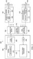
- FIGURE 5 is a high level block diagram for the electro-optic portions of an electro-optic range-finding device under test within a test/calibration system 200 according to embodiments of the present disclosure.
- the electro-optic system 500 may be entirely within the electro-optics of a device being tested/calibrated, except for an external power connection, and is used during testing of the electro-optic range-finding device but does not form part of the test/calibration system 200 (since it may be replaced by the electro-optic system of another device to be tested/calibrated).
- the electro-optic system 500 includes a transmitter assembly 501 including a laser diode 502 (together with any integrated synchronization control, temperature compensation circuit, etc.) and lens(es) 503, such as collimating and/or spreading lenses of the type described above.
- the transmitter assembly 501 emits pulses of light through the laser aperture 102 of the housing 101. Transmission of light pulses by the transmitter assembly 501 is based on signals from transmitter driver 504, which selectively drives four laser diodes, one for each quadrant.
- the transmitter driver 504 operates in response to pulse control circuit 505 within a processor 506.
- Processor 506 is a set of electrical circuits, preferably integrated in a single package, that are configured and optionally may be at least partially programmable to perform various signal processing on signals received at inputs to the processor 506 and control signal generation operations for producing timing and other control signals at outputs of the processor 506.
- processor 506 While any of a variety of commercial or custom processors may be used as processor 506, those skilled in the art will recognize that the term "processor,” when used herein (including in the claims submitted herewith or later presented) to reference processor 506, refers to a specific class of signal processing and control circuits commonly referred to in the relevant art as, variously, a "processor,” a “microprocessor,” a “controller,” a “microcontroller,” or a “field programmable gate array.”
- suitable commercial processors, or alternatively the design and (to the extent necessary) programming of a custom processor, to implement the processor 506 and perform the functions described herein is within the ordinary skill of technicians within the industry, when acting under the guidance of those having ordinary skill in the relevant art.
- Processor 506 preferably includes a digital signal processing (DSP) core 507, which receives digital values from on-chip analog-to-digital converter (ADC) 508.
- the digital values received by DSP core 507 are representative of the analog output sampled, periodically or under asynchronous control, from peak detector and/or multiplexer 509.
- the peak detector portion of peak detector and/or multiplexer 509 may, for example, be a circuit latching a peak analog value received.
- the multiplexer portion of peak detector and/or multiplexer 509 multiplexes between the outputs of receiver assemblies for each of the four quadrants.
- the receiver assembly 510 for the same quadrant containing transmitter assembly 501 thus provides one input to the peak detector and/or multiplexer 509.
- the receiver assembly 510 includes a detector 511 (e.g., a photodiode or the like, together with any integrated amplifier(s), temperature compensation circuit, signal conditioning circuit, etc.) and receiver optic(s) 512, which may include lenses, optical filter(s), polarizers, and the like.
- the receiver assembly 510 receives return of "reflected" light through the detector aperture 106 of the housing 101.
- Electro-optic system 500 also includes a battery and/or power input 513 for powering the remaining electrical components of the electro-optic system 500, with the power connections omitted from FIGURE 5 for clarity.
- Processor 506 includes a memory 514, which in the example shown is an erasable, electrically programmable read only memory (such as flash memory), that contains instructions executable by the DSP core 507, pulse control 505 and other programmable circuits within the processor 506.
- a portion of the program of machine-executable instructions within the memory 514 is a set of test/calibrate routines 515, which cause the pulse control 505 to trigger light pulses by the transmitter assembly 501 and cause the ADC 508 and DSP core 507 to process signals output by the receiver assembly responsive to return of "reflected" light.
- test/calibrate routines 515 for processor 506 when used with the test/calibration system 200 are very similar to the corresponding test and calibration software that would be used by the same processor when the device is operated with the test/calibration system 100.
- the time-of-flight and amplitude measured for the return of "reflected" light are used to confirm or adjust and set thresholds for the AOTD being operated with the test/calibration system 200 to use in determining that a target is within a predetermined range, and/or to determine whether the target is getting closer or further away from the AOTD.
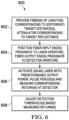
- FIGURE 6 is a high level flow diagram for test/calibration of an electro-optic range-finding device according to one embodiment of the present disclosure.
- the process may be employed with the test/calibration system configuration of FIGURE 2 and the optical range-finding system of FIGURE 5 , or with other optical range-finding systems.
- the process 600 begins with providing one or more fiber(s) with a length corresponding to a target distance used for testing/calibration, each with a fiber attenuator corresponding to a reflectance of a target used for testing/calibration and light propagation through open space over the target distance (step 602).
- multiple fibers of different lengths may be employed, as well as multiple, same-length fibers for each of multiple target distances.
- the fiber input end(s) are positioned proximate to the laser aperture for the device to be tested/calibrated, and the fiber output end(s) are positioned proximate to the detector aperture (step 604).
- distance and/or relative angle of the fiber ends may be used to simulate target distance or relative position.
- the laser of the device under test is then activated and, for appropriate beam shapes, scanned across the fiber input(s), with the return(s) from the fiber output(s) measured by the detector of the device under test (step 606). Based on the measured return(s), detection threshold(s) within the device under test are confirmed or adjusted as necessary (step 608).
- the process may be repeated iteratively for a single device under test, and repeated as necessary for different devices.
- the test/calibration system of FIGURE 2 replaces the open floor space area of alternative test ranges with an appropriate array of fibers.
- the smaller per-system dimensions allow the same space to be employed with increased AOTD testing/calibration capacity. Since light signals traverse the fibers at a speed less than the speed of light in free space, the length of the fibers is chosen to correspond to the round-trip travel time of light in free space reflecting off a target at a specified distance. Since some object or target detection devices use time of flight of an EO pulse in the open to detect distance, time of flight is preserved by using an appropriate length of fiber. The physical pulse length in the fiber is also shorter than in air, but can be compensated for (to the extent necessary).
- the fibers can be coiled to reduce linear distance, creating a compact test range. Typical floor space reduction would be from a square 40 feet on each side to a square of about 24 inches on each side.
- Location of multiple fibers along a line parallel to the AOTD axis is used for beam dissection, and location of the fiber inputs can be arranged to scan across a fan beam to provide diagnostics of beam height as the AOTD rotates.
- the location of the fiber outputs can be arranged to represent different target distances. Selectable combinations of fiber input and output can provide test set diagnostics for each AOTD.
Landscapes
- Physics & Mathematics (AREA)
- Engineering & Computer Science (AREA)
- General Physics & Mathematics (AREA)
- Computer Networks & Wireless Communication (AREA)
- Radar, Positioning & Navigation (AREA)
- Remote Sensing (AREA)
- Electromagnetism (AREA)
- Nonlinear Science (AREA)
- Optics & Photonics (AREA)
- Optical Radar Systems And Details Thereof (AREA)
Description
- The present disclosure is directed in general to test or calibration systems for optical target detectors and more particularly to reducing the space required for and the accuracy of such test or calibration systems.
- Optical target detectors may be tested and/or calibrated using a flat target of known reflectance at several distances. However, the space required can be sizable and costly, and accuracy may be influenced by spurious reflectance or emissions from background objects.
-
RU 2 636 797 C1 -
US 4 068 952 A discloses a test unit for a laser range finder comprising a laser transmitter and laser receiver, the laser range finder having a signal transmission path and a single signal reception path comprising: an optical waveguide comprised of a plurality of sequential sections including an input section, each section having ends; input optical means positioned to direct light energy in the signal transmission path to an input end of the input section; signal sampling means including a plurality of sampling structures each coupling the corresponding ends of sequential sections to provide gaps of a predetermined length for tapping a portion of the light energy from the optical waveguide; and superposition optical means for directing the sampled light energy to the single signal reception path. -
US 4 627 723 A discloses an optical range simulator device for testing the ranging function of a laser rangefinder that receives output pulses from the rangefinder and delivers these to an optical fibre delay line. The output of the delay line and the input of the fibre delay line are interconnected by an optical bridging means which collects at least a portion of each pulse delivered by the output of the delay line and recirculates that pulse portion to the input end of the delay line, the remaining portion of each pulse at the output end of the delay line being returned to the rangefinder so that for each output pulse received from the rangefinder the simulator device delivers a series of successively delayed return pulses to the rangefinder, these delayed return pulses being representative of ranges successively augmented by the range distance represented by the delay line. -
US 5 825 464 A discloses a calibration system and method including isotropically diffusing high-intensity light emitted from a detection apparatus, with the diffused light being coupled to at least one optical line, typically an optical fiber. In the preferred embodiment, the apparatus to be calibrated is a light detection and ranging (LIDAR) apparatus and the isotropic diffusion is achieved by means of an integrating sphere. For calibrating distance calculations, the optical fiber includes a reflecting mechanism, such as Bragg gratings, at a fixed and known distance from the input end of the optical fiber. The reflecting mechanism simulates the presence of a remote object at the known distance. For a velocity calculation, a frequency offset may be introduced to the light propagating through the optical fiber, thereby simulating a Doppler shift induced by a moving object. The simulations of the presence and movement of remote objects are used to calibrate the apparatus. -
CN 107 390 201 A -
US 4 189 233 A discloses a passive optical range simulator device which can be used to test the ranging function of an optical radar ranger system having parallel beams leaving and entering. An adapter member provides for mechanical coupling and optical alignment of the simulator device with the ranger system. A focusing lens transforms parallel beams entering and leaving the ranger system into focused beams entering and leaving one end of a coil of optical fiber having a mirror at its opposite end to act as an optical delay medium. A primary tilted-glass-element optical attenuator limits optical energy allowed to reach the optical fiber entrance face, while deflecting first surface reflection away from ranger system input. A removable attenuator assembly having oppositely-tilted flat glass elements at the fiber entrance face permits, by substitution, fine adjustment of beam attenuation. An X-Y-Z translation assembly for the fiber entrance face, together with a light source at the opposite end of the fiber, provides for proper alignment with the focused beams. -
US 4 552 454 A discloses a test system for a laser rangefinder having signal transmission and reception paths comprising a thick lens collimator which receives energy from a transmitter for input through an optical fiber. The fiber has a partial reflector and a full reflector to simulate sites of targets, and the reflected energy is transmitted back through collimator to a receiver. Partial reflection of energy is provided by gold placed on a surface of one of two aligned and spaced termini of fiber. - In a first aspect, the present disclosure provides a test equipment, comprising: multiple fiber bundles each having a length selected to correspond to a predetermined time-of-flight for light pulses to travel from a laser aperture of an electro-optic range-finding device to a target and back to a detector aperture of the range-finding device, wherein an input end of each of the fiber bundles is configured for being positioned proximate to the laser aperture and to receive a portion of light emitted through the laser aperture, wherein the input ends of the fiber bundles are positioned at different angular positions and are oriented toward a common point; an output end of each of the fiber bundles is configured for being positioned proximate to the detector aperture and to emit light from the respective fiber bundle through the detector aperture; and each of the fiber bundles comprises a plurality of fibers; fiber attenuators connected along the fibers of the fiber bundles, each fiber attenuator configured to attenuate an amplitude of light propagating through the respective fiber by an amount corresponding to a target of known reflectance and distance; and a positional mask configured to be positioned between the input end of a specified one of the fiber bundles and the laser aperture of the range-finding device, the positional mask including an aperture that is configured to be shifted into alignment with one of the fiber ends and that allows light from the laser aperture to enter one of the fibers of the specified fiber bundle while blocking light from the laser aperture from entering one or more remaining fibers of the specified fiber bundle.
- In a second aspect, the present disclosure provides a method, comprising: operating an electro-optic range-finding device to emit light pulses through a laser aperture and receive light through a detector aperture; positioning multiple fiber bundles to carry a portion of light in the light pulses from the laser aperture to the detector aperture, the fiber bundles each having a length selected to correspond to a predetermined time-of-flight for the light pulses to travel from the laser aperture to the detector aperture, wherein an input end of each of the fiber bundles is positioned proximate to the laser aperture and is configured to receive a portion of light emitted through the laser aperture, wherein the input ends of the fiber bundles are positioned at different angular positions and are oriented toward a common point; an output end of each of the fiber bundles is positioned proximate to the detector aperture and is configured to emit light from the respective fiber bundle through the detector aperture; and each of the fiber bundles comprises a plurality of fibers; using each of multiple fiber attenuators connected along the fibers of the fiber bundles to attenuate an amplitude of light propagating through the respective fiber by an amount corresponding to a target of known reflectance and distance; and using a positional mask positioned between the input end of a specified one of the fiber bundles and the laser aperture of the range-finding device, the positional mask including an aperture that is shifted into alignment with one of the fiber ends and that allows light from the laser aperture to enter one of the fibers of the specified fiber bundle while blocking light from the laser aperture from entering one or more remaining fibers of the specified fiber bundle.
- In a third aspect, the present disclosure provides an apparatus, comprising: a first fiber bundle having a first length selected such that time-of-flight for light pulses to travel from an input end of the first fiber bundle to an output end of the first fiber bundle corresponds to a time-of-flight for the light pulses to travel a first distance in open air, wherein the first fiber bundle comprises a plurality of first fibers; first fiber attenuators connected along the first fibers of the first fiber bundle and each configured to attenuate an amplitude of light propagating through the respective first fiber by an amount corresponding to reflection of light traveling in open air from a target of known reflectance at the first distance; a second fiber bundle having a second length selected such that time-of-flight for light pulses to travel from an input end of the second fiber bundle to an output end of the second fiber bundle corresponds to a time-of-flight for the light pulses to travel a second distance in open air, wherein the second fiber bundle comprises a plurality of second fibers; second fiber attenuators connected along the second fibers of the second fiber bundle and each configured to attenuate an amplitude of light propagating through the respective second fiber by an amount corresponding to reflection of light traveling in open air from the target of known reflectance at the second distance; and a positional mask disposed at the input end of the first fiber bundle, the positional mask including an aperture that is configured to be shifted into alignment with one of the fiber ends and that allows light from a laser aperture to enter one of the first fibers of the first fiber bundle while blocking light from the laser aperture from entering one or more remaining fibers of the first fiber bundle, wherein the first and second fiber bundles are coiled to reduce a linear distance over which the first and second fiber bundles extend, and wherein the input ends of the first and second fiber bundles are positioned at different angular positions and are oriented toward a common point.
- For a more complete understanding of the present disclosure and its advantages, reference is now made to the following description taken in conjunction with the accompanying drawings, in which like reference numerals represent like parts:
-
FIGURES 1 and 2 are comparative, high-level diagrams illustrating an electro-optic range-finding device under test and test/calibration system configurations respectively for one alternative to the present disclosure and for embodiments in accordance with the present disclosure; -
FIGURE 3 is a diagram schematically illustrating the placement of input ends for glass fibers in the test/configuration system ofFIGURE 2 relative to a laser transmitter of an electro-optic range-finding device under test; -
FIGURE 4 is a diagram schematically illustrating multiple glass fiber ends with an associated positional mask and optional shroud used for either input or output ends of the glass fibers in the test/configuration system ofFIGURE 2 ; -
FIGURE 5 is a high level block diagram for the electro-optic portions of an electro-optic range-finding device under test within a test/calibration system according to embodiments of the present disclosure; and -
FIGURE 6 is a high level flow diagram for test/calibration of an electro-optic range-finding device according to one embodiment of the present disclosure. - Electro-optic (EO) devices such as active optical target detectors (AOTDs) may be employed to detect objects over a range of distances. For example, a missile equipped with "near miss" detection, in order to detonate munitions when the target is within a predetermined range despite the lack of a direct hit, may detect decreasing and then increasing distance to the target as well as whether the current range to the target is less than a maximum distance at which detonation might affect the target. AOTDs of that type often require a "Test Range" to test operability and/or to confirm or set the value of the detection threshold. As a result, AOTDs and similar devices may be tested and calibrated with a flat target of known reflectance at several distances. During this process, the AOTD is generally rotated around its longitudinal axis to scan the fan beam for each 90° quadrant (there are typically four transceivers per AOTD) across a narrow target. Given the target distances, however, test ranges for the test/calibration system may take up a large amount of costly floor space, typically on the order of 40 feet × 40 feet.
-
FIGURES 1 and 2 are comparative, high-level diagrams illustrating an electro-optic range-finding device under test and test/calibration system configurations respectively for one alternative to the present disclosure and for embodiments in accordance with the present disclosure. Although depicted in each ofFIGURE 1 and 2 for purposes of explanation, the electro-optic range-finding device is used with, but does not form part of, the respective test/calibration system, and may be replaced with another electro-optic range-finding device of the same or different type. In addition, while the test/calibration system configurations ofFIGURE 1 and 2 are illustrated for an electro-optic range-finding device having separate, spaced-apart laser and detector apertures (i.e., for which the target exhibits parallax), the test/calibration system ofFIGURE 2 may be readily modified for use with an electro-optic range-finding device having a single, common laser and detector aperture, -
FIGURE 1 illustrates an electro-optic range-finding device under test and a test/calibration system configuration for one alternative to the present disclosure which does not fall within the claimed subject-matter. InFIGURE 1 , the test/calibration system 100 is positioned proximate to an AOTD under test that includes four transceivers, one per quadrant, within ahousing 101, with each quadrant of thehousing 101 including alaser aperture 102 through which a beam of laser pulses is emitted. The AOTD may be, for example, an active ranging device used for air-to-air determination of the distance to a target. Typically, for that application, a thin (almost planar) 90° fan beam of laser pulses is emitted through the laser aperture toward a target to illuminate a 90° quadrant and, if the target is at least partially within the plane of the fan beam, "paint" a line across that target. Thelaser aperture 102 may be covered by a material that is substantially transparent to the wavelength(s) of the laser beam pulses. - Within the test/
calibration system 100, atarget 103 of predetermined size and having known reflectance for the wavelength(s) of the laser pulses is positioned within the plane of the fan beam at a predetermined distance from thelaser aperture 102, to be irradiated by theportion 104 of the laser pulses. From theportion 104 of the fan beam of laser pulses that impinges on thetarget 103, some part is reflected (scattered) by thetarget 103 back in the direction of thehousing 101 for the AOTD.Return signals 105, which comprise the portion of the impinging laser beam pulses reflected off thetarget 103 in the direction of the AOTDhousing 101, are received through adetector aperture 106 in thehousing 101 for the respective quadrant, and used for testing/calibration. As with thelaser aperture 102, thedetector aperture 106 may be covered by a material that is substantially transparent to the wavelength(s) of the laser beam pulses. - As apparent, there exists some
parallax separation 107 between thelaser aperture 102 and thedetector aperture 106 in each quadrant. Thetarget 103 is positioned with a known three-dimensional orientation relative to the lines-of-sight from thelaser aperture 102 and the detector aperture 106-e.g., "normal" (in the sense of being perpendicular for two independent directions) to a line from the center point between thelaser aperture 102 and thedetector aperture 106. Due to theparallax separation 107, return signals 105 may differ when thetarget 103 is located at different positions relative to thelaser aperture 102 anddetector aperture 106, particularly for different distances (even with the same relative orientation). Accordingly, thetarget 103 may be positioned at different distances from thehousing 101 during testing/calibration, to exploit the correlation between the target distance and the return angle of the reflected laser pulses at thedetector aperture 106. Based on the maximum distance required for the testing/calibration to be acceptable and complete, a 40 feet × 40 feet test range is required, even when each transceiver within the AOTD is individually tested from one corner of the test range. -
FIGURE 2 illustrates an electro-optic range-finding device under test and a test/calibration system configuration according to embodiments of the present disclosure. InFIGURE 2 , the test/calibration system 200 is also positioned proximate to an AOTD under test that includes four transceivers, one per quadrant, within ahousing 101, with each quadrant of thehousing 101 including thelaser aperture 102 and thedetector aperture 106 as described above. In test/calibration system 200, however,glass fibers 201, 202 (also known as "optical fibers" or "fiber optics") receive a portion of the 90° fan beam emitted through thelaser aperture 102. First, receiving or "input" ends of theglass fibers laser aperture 102 by a support (not shown inFIGURE 2 ), with the ends positioned in the fan beam to receive emitted laser pulses and with apositional mask 203 allowing flexible and robust selection of the portion of the fan beam received. Second, emitting or "output" ends of theglass fibers detector aperture 106 by the support, with the ends positioned to emit "reflected" light pulses into thedetector aperture 106 and with apositional mask 204 allowing flexible and robust selection of the "reflected" light received by the AOTD receiver. The height and relative angle of the emitting ends ofglass fibers - The
glass fibers longer glass fiber 202, from input end to output end, than along the entirety of theshorter glass fiber 201, to correlate to the round-trip travel time for the different target distance.Glass fibers fiber attenuator longer glass fiber 202, from input end to output end, will be reduced more than the amplitude of laser pulses propagating along theshorter glass fiber 201, to correlate to the target distance. The amplitude of all pulses may also be reduced by an additional increment correlating to the target reflectance. Similar to operation with the test/calibration system ofFIGURE 1 , the AOTD rotates relative to the "target" (inFIGURE 2 , the fibers) to scan the fiber input and output across each respective quadrant. For the system ofFIGURE 2 , replacing direct light paths and a target with optical fibers and attenuators, the floor space required is reduced to less than 2 feet × 2 feet. - By selection of characteristics for the
glass fibers fiber attenuators calibration system 200 may be reduced or minimized. Theglass fibers fiber attenuators calibration system 200 behaves substantially similarly to the test/calibration system 100. As noted above, the length ofglass fibers target 103 for one of the test distances used with the test/calibration system 100 (with the difference in the time of transit for the light pulses through air and the medium of theglass fibers calibration system 200 may thus effectively match the corresponding delay in the test/calibration system 100. As also noted above,fiber attenuators target 103 with known reflectance used with the test/calibration system 100, and (b) travel by the light pulses of a predetermined distance through open space. In addition, the angle of an axial center for the input ends of theglass fibers glass fibers calibration system 200 may each be set to correspond to a corresponding target location for the test/calibration system 100. With such a design, only nominal changes to the test/calibration software should be required. -
FIGURE 3 is a diagram schematically illustrating the placement of input ends for glass fibers in the test/configuration system ofFIGURE 2 relative to a laser transmitter of an electro-optic range-finding device under test. Thelaser transmitter 300 for one quadrant in an AOTD includes alaser diode 301 with electrical connections to control circuitry (not shown) for controlling thelaser diode 301 to emit pulses of light. The emitted light passes through collimating lens(es) 302 and, for the embodiment ofFIGURES 2 and3 , spreader lens(es) 304 forming a fan beam for each light pulse. In other embodiments with EO devices employing substantially collimated cylindrical ("pencil-beam") or conical emitted light, the spreader lens(es) 304 may be omitted or replaced with other optical devices, such as polarizers, filters, or the like. - The
laser transmitter 300 is mounted within thehousing 101 of the AOTD proximate to thelaser aperture 102, to emit light through the laser aperture. As described above, thelaser aperture 102 may be covered by a material (not shown inFIGURE 3 ) largely transparent to the laser light. During testing/calibration, the input ends 305a, 305b, and 305c of the glass fibers (e.g.,glass fibers FIGURE 2 ) are held proximate to the exterior surface of such transparent cover. As used herein, the term "proximate," when used to describe the position of input ends of glass fibers to an EO device being tested/calibrated, means sufficient both to interpose a positional mask (e.g.,positional masks FIGURE 2 ) between the EO device and the nearest surface of the input ends facing the EO and to leave enough clearance between the transparent cover over the laser aperture and the nearest surfaces of the input ends (or the interposing positional mask) facing that transparent cover to allow rotation of the AOTD during testing. Otherwise, however, the distance is preferably predetermined and consistently reproducible during testing of different AOTDs using the test/calibration system 200. It should be noted that the apparent discrepancy between the twoglass fibers FIGURE 2 and the three input ends 305a, 305b, and 305c of the glass fibers depicted inFIGURE 3 is deliberate, to emphasize that the number ofglass fibers - As shown in
FIGURE 3 , the input ends 305a, 305b, and 305c of the glass fibers may be positioned at different angular positions relative to the spread of the emitted fan beam, all oriented toward a common point. Generally, the energy of light pulses from the laser transmitter is spread over approximately 90° to intersect the field of view at a constant range for all roll angles. For such fan beams, it may be beneficial to distribute the input ends 305a, 305b, and 305c of the glass fibers at different angular positions relative to the fan beam's centerline and ±45° edges-that is, at different positions surrounding part of the AOTD's circumferential perimeter. This allows the test/calibration system 200 to effectively scan across the fan beam to provide diagnostics of beam characteristics as the AOTD rotates. In that respect, is should be noted thatFIGURE 3 is intended to be in the nature of a plan view for the fan beam of the laser transmitter. A side view of the same fan beam would be similar, but with much less spread. Nonetheless, multiple input ends of the glass fibers may likewise be positioned at different angular positions relative to the vertical spread of the emitted fan beam-that is, at different positions along the height of the AOTD-but similarly oriented toward the same common point as the input ends 305a, 305b, and 305c shown inFIGURE 3 . Such vertical distribution of the glass fiber input ends relative to the AOTD's height may be used for beam dissection. - While a distribution of single input ends 305a, 305b, and 305c is illustrated in
FIGURE 3 , those skilled in the art will recognize that each input end depicted inFIGURE 3 may in in fact comprise a plurality of close-spaced glass fiber input ends. That is, each ofglass fiber FIGURE 2 actually comprises a bundle of closely-spaced glass fibers, such that both the input ends and the output ends are likewise closely-spaced. As used herein, "fiber bundle" or "bundle of fibers" comprises a plurality of fibers. As used herein, "closely-spaced," when used to describe glass fiber ends, means having a spacing that results in negligible changes in received or emitted light, such that the closely-spaced glass fiber ends may be treated as receiving or emitting the same light, and in contrast to deliberate spacing of the glass fiber ends at different locations along the perimeter or height of the fan beam as previously described. For example,FIGURE 4 diagrammatically illustrates three closely spaced glass fiber ends and an associatedpositional mask 401 of the type described above in connection withFIGURE 2 . The opaque, rectangular positional mask shown in cross-section inFIGURE 4 is disposed near the glass fiber ends, with an aperture that may be shifted into alignment with one of the fiber ends either to allow light from the AOTD to pass into the respective one of the glass fiber ends while blocking light from the AOTD from entering the remaining glass fiber ends (for input ends), or to allow light from the glass fiber to pass from the respective one of the glass fiber ends onto the AOTD while blocking light from the remaining glass fiber ends from reaching the AOTD (for output ends). - Thus, for example, the
input end 305a depicted inFIGURE 3 may actually comprise the ends of three (or fewer, or more) glass fibers that are effectively multiplexed by shifting the associated positional mask so that the aperture is aligned with a selected one. Likewise, the output ends ofglass fibers FIGURE 2 may comprise a plurality of close-spaced fiber ends with (optionally) an associatedpositional mask 401 of the type depicted inFIGURE 4 for effectively multiplexing light from the glass fibers. It should be noted that a positional mask associated with only one of either the input ends or the output ends of a closely-spaced bundle of glass fibers may be sufficient, or that coordinately-controlled positional masks associated with each of the input ends and the output ends may be employed. - Referring back to
FIGURE 3 , the input ends 305a, 305b, and 305c (and optional associated positional mask) are each held in position relative to the transparent cover over thelaser aperture 102 for an AOTD being tested/calibrated bymounts 306. Eachmount 306 may be fixed or adjustable, and should hold the respective glass fiber end(s) within a predetermined spacing from and relative orientation to thelaser aperture 102 for the AOTD being tested. In some embodiments, themounts 306 may be supported by a common frame and may be adjustable to hold the respective glass fiber end(s) at preset positions having the predetermined spacing from and relative orientation to a particular EO device being tested. Thus, for example, a certain preset position for each of themounts 306 would correspond to the fan beam AOTD previously described, while another preset position for eachmount 306 would correspond to a different type of AOTD, such as a device using differently-shaped collimated light. - Referring once again to
FIGURE 2 , thedetector aperture 106 may also be covered by a material largely transparent to the laser light and, during testing/calibration, the output ends of theglass fibers laser aperture 102 and transparent cover, and themounts 306 also applies to the glass fiber output ends, thedetector aperture 106 and a transparent cover for that aperture, and mounts holding the glass fiber output ends. Rather than positioning input ends relative to a fan beam, as described in connection withFIGURE 3 , the output ends are instead positioned relative to the detector's field of view. Therefore, to avoid unnecessary duplication, and for simplicity and clarity, the description above regarding the input ends of theglass fibers FIGURE 2 will not be repeated for the output ends. Those skilled in the art will recognize that, for testing/calibration of an electro-optic range-finding device having a single, common laser and detector aperture, thesame mounts 306 may hold both the glass fiber input ends and the glass fiber output ends. - The test/
calibration system 100 also permits the possibility of background reflection (off surrounding objects) returning light from thelaser aperture 102 to thedetector aperture 106, as well as reflection off thetarget 103. The use ofglass fibers calibration system 200 mitigates that possibility, particularly if at least the output ends of theglass fibers detector aperture 106 are at least partially enclosed by ashroud 402 such as is depicted inFIGURE 4 . Theshroud 402 may be formed of an opaque, flexible material that is positioned to lightly contact (or not contact) thehousing 101 around thedetector aperture 106, without interfering with rotation of the AOTD during testing/calibration. -
FIGURE 5 is a high level block diagram for the electro-optic portions of an electro-optic range-finding device under test within a test/calibration system 200 according to embodiments of the present disclosure. The electro-optic system 500 may be entirely within the electro-optics of a device being tested/calibrated, except for an external power connection, and is used during testing of the electro-optic range-finding device but does not form part of the test/calibration system 200 (since it may be replaced by the electro-optic system of another device to be tested/calibrated). The electro-optic system 500 includes atransmitter assembly 501 including a laser diode 502 (together with any integrated synchronization control, temperature compensation circuit, etc.) and lens(es) 503, such as collimating and/or spreading lenses of the type described above. Thetransmitter assembly 501 emits pulses of light through thelaser aperture 102 of thehousing 101. Transmission of light pulses by thetransmitter assembly 501 is based on signals fromtransmitter driver 504, which selectively drives four laser diodes, one for each quadrant. Thetransmitter driver 504 operates in response topulse control circuit 505 within aprocessor 506. -
Processor 506 is a set of electrical circuits, preferably integrated in a single package, that are configured and optionally may be at least partially programmable to perform various signal processing on signals received at inputs to theprocessor 506 and control signal generation operations for producing timing and other control signals at outputs of theprocessor 506. While any of a variety of commercial or custom processors may be used asprocessor 506, those skilled in the art will recognize that the term "processor," when used herein (including in the claims submitted herewith or later presented) toreference processor 506, refers to a specific class of signal processing and control circuits commonly referred to in the relevant art as, variously, a "processor," a "microprocessor," a "controller," a "microcontroller," or a "field programmable gate array." The selection and programming of suitable commercial processors, or alternatively the design and (to the extent necessary) programming of a custom processor, to implement theprocessor 506 and perform the functions described herein is within the ordinary skill of technicians within the industry, when acting under the guidance of those having ordinary skill in the relevant art. -
Processor 506 preferably includes a digital signal processing (DSP)core 507, which receives digital values from on-chip analog-to-digital converter (ADC) 508. The digital values received byDSP core 507 are representative of the analog output sampled, periodically or under asynchronous control, from peak detector and/ormultiplexer 509. The peak detector portion of peak detector and/ormultiplexer 509 may, for example, be a circuit latching a peak analog value received. The multiplexer portion of peak detector and/ormultiplexer 509 multiplexes between the outputs of receiver assemblies for each of the four quadrants. Thereceiver assembly 510 for the same quadrant containingtransmitter assembly 501 thus provides one input to the peak detector and/ormultiplexer 509. - The
receiver assembly 510 includes a detector 511 (e.g., a photodiode or the like, together with any integrated amplifier(s), temperature compensation circuit, signal conditioning circuit, etc.) and receiver optic(s) 512, which may include lenses, optical filter(s), polarizers, and the like. Thereceiver assembly 510 receives return of "reflected" light through thedetector aperture 106 of thehousing 101. - Electro-
optic system 500 also includes a battery and/orpower input 513 for powering the remaining electrical components of the electro-optic system 500, with the power connections omitted fromFIGURE 5 for clarity. -
Processor 506 includes amemory 514, which in the example shown is an erasable, electrically programmable read only memory (such as flash memory), that contains instructions executable by theDSP core 507,pulse control 505 and other programmable circuits within theprocessor 506. A portion of the program of machine-executable instructions within thememory 514 is a set of test/calibrateroutines 515, which cause thepulse control 505 to trigger light pulses by thetransmitter assembly 501 and cause theADC 508 andDSP core 507 to process signals output by the receiver assembly responsive to return of "reflected" light. When the electro-optic system 500 is used in connection with the test/calibration system 200, the return is actually light propagated alongglass fibers positional masks laser aperture 102 anddetector aperture 106. As a result, the test/calibrateroutines 515 forprocessor 506 when used with the test/calibration system 200 are very similar to the corresponding test and calibration software that would be used by the same processor when the device is operated with the test/calibration system 100. That is, the time-of-flight and amplitude measured for the return of "reflected" light are used to confirm or adjust and set thresholds for the AOTD being operated with the test/calibration system 200 to use in determining that a target is within a predetermined range, and/or to determine whether the target is getting closer or further away from the AOTD. -
FIGURE 6 is a high level flow diagram for test/calibration of an electro-optic range-finding device according to one embodiment of the present disclosure. The process may be employed with the test/calibration system configuration ofFIGURE 2 and the optical range-finding system ofFIGURE 5 , or with other optical range-finding systems. Theprocess 600 begins with providing one or more fiber(s) with a length corresponding to a target distance used for testing/calibration, each with a fiber attenuator corresponding to a reflectance of a target used for testing/calibration and light propagation through open space over the target distance (step 602). As discussed above, multiple fibers of different lengths may be employed, as well as multiple, same-length fibers for each of multiple target distances. The fiber input end(s) are positioned proximate to the laser aperture for the device to be tested/calibrated, and the fiber output end(s) are positioned proximate to the detector aperture (step 604). As discussed above, distance and/or relative angle of the fiber ends may be used to simulate target distance or relative position. The laser of the device under test is then activated and, for appropriate beam shapes, scanned across the fiber input(s), with the return(s) from the fiber output(s) measured by the detector of the device under test (step 606). Based on the measured return(s), detection threshold(s) within the device under test are confirmed or adjusted as necessary (step 608). The process may be repeated iteratively for a single device under test, and repeated as necessary for different devices. - Providing a more compact test range of the type depicted in
FIGURE 2 with adequate propagation of test signals meets a long-felt need in EO device testing and/or calibration. As discussed, current ranges operate in the open air requiring large spaces. With the use of optical fiber in place of open air paths as disclosed, coiling the fiber can greatly reduce the space required. - The test/calibration system of
FIGURE 2 replaces the open floor space area of alternative test ranges with an appropriate array of fibers. The smaller per-system dimensions allow the same space to be employed with increased AOTD testing/calibration capacity. Since light signals traverse the fibers at a speed less than the speed of light in free space, the length of the fibers is chosen to correspond to the round-trip travel time of light in free space reflecting off a target at a specified distance. Since some object or target detection devices use time of flight of an EO pulse in the open to detect distance, time of flight is preserved by using an appropriate length of fiber. The physical pulse length in the fiber is also shorter than in air, but can be compensated for (to the extent necessary). - The fibers can be coiled to reduce linear distance, creating a compact test range. Typical floor space reduction would be from a square 40 feet on each side to a square of about 24 inches on each side. Location of multiple fibers along a line parallel to the AOTD axis is used for beam dissection, and location of the fiber inputs can be arranged to scan across a fan beam to provide diagnostics of beam height as the AOTD rotates. The location of the fiber outputs can be arranged to represent different target distances. Selectable combinations of fiber input and output can provide test set diagnostics for each AOTD.
Claims (15)
- A test equipment (100), comprising:multiple fiber bundles (201, 202, 305a-c) each having a length selected to correspond to a predetermined time-of-flight for light pulses to travel from a laser aperture (102) of an electro-optic range-finding device to a target and back to a detector aperture (106) of the range-finding device, whereinan input end of each of the fiber bundles is configured for being positioned proximate to the laser aperture and to receive a portion of light emitted through the laser aperture, wherein the input ends of the fiber bundles are positioned at different angular positions and are oriented toward a common point;an output end of each of the fiber bundles is configured for being positioned proximate to the detector aperture and to emit light from the respective fiber bundle through the detector aperture; andeach of the fiber bundles comprises a plurality of fibers;fiber attenuators (205, 206) connected along the fibers of the fiber bundles, each fiber attenuator configured to attenuate an amplitude of light propagating through the respective fiber by an amount corresponding to a target of known reflectance and distance; anda positional mask (203, 401) configured to be positioned between the input end of a specified one of the fiber bundles and the laser aperture of the range-finding device, the positional mask including an aperture that is configured to be shifted into alignment with one of the fiber ends and that allows light from the laser aperture to enter one of the fibers of the specified fiber bundle while blocking light from the laser aperture from entering one or more remaining fibers of the specified fiber bundle.
- The test equipment according to Claim 1, wherein the fiber bundles are each coiled to reduce a linear distance over which the fiber bundles extend.
- The test equipment according to Claim 1, wherein the fiber bundles comprise:a first fiber bundle (201) having a first length corresponding to a first time-of-flight for light pulses; anda second fiber bundle (202) having a second length corresponding to a second time-of-flight for light pulses.
- The test equipment according to Claim 3, wherein:the fiber attenuators (205) connected along the fibers of the first fiber bundle are each configured to attenuate an amplitude of light pulses within the respective fiber by at least an amount corresponding to the first time-of-flight for light pulses propagating a first distance in open air; andthe fiber attenuators (206) connected along the fibers of the second fiber bundle are each configured to attenuate an amplitude of light pulses within the respective fiber by at least an amount corresponding to the second time-of-flight for light pulses propagating a second distance in open air.
- The test equipment according to Claim 1, wherein the input ends of the fiber bundles are distributed at spaced-apart points along a cross-section of the light emitted through the laser aperture.
- The test equipment according to Claim 1, wherein the test equipment further comprises:a second positional mask (204) configured to be positioned between the output end of the specified one of the fiber bundles and the detector aperture of the range-finding device, the second positional mask including an aperture that allows light from one of the fibers of the specified fiber bundle to enter the detector aperture while blocking light from one or more remaining fibers of the specified fiber bundle from entering the detector aperture; andpreferably, wherein at least one of:the positional mask is configured to multiplex light from the laser aperture to the fibers; orthe second positional mask is configured to multiplex light from the fibers to the detector aperture.
- A method, comprising:operating an electro-optic range-finding device to emit light pulses through a laser aperture (102) and receive light through a detector aperture (106);positioning (602) multiple fiber bundles (201, 202, 305a-c) to carry a portion of light in the light pulses from the laser aperture to the detector aperture, the fiber bundles each having a length selected to correspond to a predetermined time-of-flight for the light pulses to travel from the laser aperture to the detector aperture, whereinan input end of each of the fiber bundles is positioned (604) proximate to the laser aperture and is configured to receive a portion of light emitted through the laser aperture, wherein the input ends of the fiber bundles are positioned at different angular positions and are oriented toward a common point;an output end of each of the fiber bundles is positioned (604) proximate to the detector aperture and is configured to emit light from the respective fiber bundle through the detector aperture; andeach of the fiber bundles comprises a plurality of fibers;using each of multiple fiber attenuators (205, 206) connected along the fibers of the fiber bundles to attenuate an amplitude of light propagating through the respective fiber by an amount corresponding to a target of known reflectance and distance; andusing a positional mask (203, 401) positioned between the input end of a specified one of the fiber bundles and the laser aperture of the range-finding device, the positional mask including an aperture that is shifted into alignment with one of the fiber ends and that allows light from the laser aperture to enter one of the fibers of the specified fiber bundle while blocking light from the laser aperture from entering one or more remaining fibers of the specified fiber bundle.
- The method according to Claim 7, further comprising:
coiling the fiber bundles to reduce a linear distance over which the fiber bundles extend. - The method according to Claim 7, wherein the fiber bundles comprise:a first fiber bundle (201) having a first length corresponding to a first time-of-flight for light pulses; anda second fiber bundle (202) having a second length corresponding to a second time-of-flight for light pulses.
- The method according to Claim 9, wherein:the fiber attenuators (205) connected along the fibers of the first fiber bundle each attenuate an amplitude of light pulses within the respective fiber by at least an amount corresponding to the first time-of-flight for light pulses propagating a first distance in open air; andthe fiber attenuators (206) connected along the fibers of the second fiber bundle each attenuate an amplitude of light pulses within the respective fiber by at least an amount corresponding to the second time-of-flight for light pulses propagating a second distance in open air.
- The method according to Claim 7, wherein:
the input ends of the fiber bundles are distributed at spaced-apart points along a cross-section of the light emitted through the laser aperture. - The method according to Claim 7, further comprising:using a second positional mask (204) positioned between the output end of the specified one of the fiber bundles and the detector aperture of the range-finding device, the second positional mask including an aperture that allows light from one of the fibers of the specified fiber bundle to enter the detector aperture while blocking light from one or more remaining fibers of the specified fiber bundle from entering the detector aperture; andpreferably, wherein at least one of:the positional mask multiplexes light from the laser aperture to the fibers; orthe second positional mask multiplexes light from the fibers to the detector aperture.
- An apparatus, comprising:a first fiber bundle (201) having a first length selected such that time-of-flight for light pulses to travel from an input end of the first fiber bundle to an output end of the first fiber bundle corresponds to a time-of-flight for the light pulses to travel a first distance in open air, wherein the first fiber bundle comprises a plurality of first fibers;first fiber attenuators (205) connected along the first fibers of the first fiber bundle and each configured to attenuate an amplitude of light propagating through the respective first fiber by an amount corresponding to reflection of light traveling in open air from a target of known reflectance at the first distance;a second fiber bundle (202) having a second length selected such that time-of-flight for light pulses to travel from an input end of the second fiber bundle to an output end of the second fiber bundle corresponds to a time-of-flight for the light pulses to travel a second distance in open air, wherein the second fiber bundle comprises a plurality of second fibers;second fiber attenuators (206) connected along the second fibers of the second fiber bundle and each configured to attenuate an amplitude of light propagating through the respective second fiber by an amount corresponding to reflection of light traveling in open air from the target of known reflectance at the second distance; anda positional mask (203, 401) disposed at the input end of the first fiber bundle, the positional mask including an aperture that is configured to be shifted into alignment with one of the fiber ends and that allows light from a laser aperture to enter one of the first fibers of the first fiber bundle while blocking light from the laser aperture from entering one or more remaining first fibers of the first fiber bundle,wherein the first and second fiber bundles are coiled to reduce a linear distance over which the first and second fiber bundles extend, andwherein the input ends of the first and second fiber bundles are positioned at different angular positions and are oriented toward a common point.
- A system comprising the apparatus according to Claim 13, wherein the system further comprises:
an electro-optic range-finding device (500) having the laser aperture and a detector aperture, wherein the input end of each of the first and second fiber bundles is positioned proximate to the laser aperture and is configured to receive a portion of light emitted through the laser aperture, and wherein the output end of each of the first and second fiber bundles is positioned proximate to the detector aperture and is configured to emit light from the respective fiber bundle through the detector aperture, wherein the electro-optic range-finding device further comprises:a light transmitter assembly (501) configured to emit the light pulses through the laser aperture;a light receiver assembly (510) configured to receive light through the detector aperture; anda processor (506) configured to calibrate the electro-optic range-finding device based on light received through the detector aperture from the first and second fiber bundles based on light emitted through the laser aperture into the first and second fiber bundles. - The system according to Claim 14, wherein the input end of each of the fiber bundles, positioned proximate to the laser aperture, and the output end of each of the fiber bundles, positioned proximate to the detector aperture, are positioned proximate to separate, spaced-apart laser and detector apertures of the electro-optic range-finding device.
Applications Claiming Priority (2)
| Application Number | Priority Date | Filing Date | Title |
|---|---|---|---|
| US15/896,256 US10564269B2 (en) | 2018-02-14 | 2018-02-14 | Compact test range for active optical target detectors |
| PCT/US2018/053239 WO2019160582A1 (en) | 2018-02-14 | 2018-09-27 | Compact test range for active optical target detectors |
Publications (2)
| Publication Number | Publication Date |
|---|---|
| EP3752854A1 EP3752854A1 (en) | 2020-12-23 |
| EP3752854B1 true EP3752854B1 (en) | 2024-06-12 |
Family
ID=63963425
Family Applications (1)
| Application Number | Title | Priority Date | Filing Date |
|---|---|---|---|
| EP18792627.4A Active EP3752854B1 (en) | 2018-02-14 | 2018-09-27 | Compact test range for active optical target detectors |
Country Status (3)
| Country | Link |
|---|---|
| US (1) | US10564269B2 (en) |
| EP (1) | EP3752854B1 (en) |
| WO (1) | WO2019160582A1 (en) |
Families Citing this family (5)
| Publication number | Priority date | Publication date | Assignee | Title |
|---|---|---|---|---|
| CN112924979B (en) * | 2019-11-20 | 2024-03-01 | 北京小米移动软件有限公司 | Multi-path light testing equipment of TOF module, depth error measuring method and system |
| EP3825725A1 (en) * | 2019-11-21 | 2021-05-26 | Robert Bosch GmbH | Distance testing arrangement for a lidar system, lidar system arrangement, and apparatus |
| JP7417859B2 (en) * | 2020-03-19 | 2024-01-19 | 株式会社リコー | Distance correction information calculation method, distance measuring device, moving object and stereo camera device |
| US12105225B2 (en) * | 2020-04-17 | 2024-10-01 | Velodyne Lidar Usa, Inc. | Systems and methods for calibrating a LiDAR device |
| WO2022033681A1 (en) * | 2020-08-13 | 2022-02-17 | Huawei Technologies Co., Ltd. | Arrangement for detecting depth measurement errors |
Family Cites Families (12)
| Publication number | Priority date | Publication date | Assignee | Title |
|---|---|---|---|---|
| US4068952A (en) | 1976-07-23 | 1978-01-17 | Hughes Aircraft Company | Range testing system having simulated optical targets |
| US4189233A (en) | 1977-03-07 | 1980-02-19 | Westinghouse Electric Corp. | Passive optical range simulator device |
| US4552454A (en) | 1983-02-08 | 1985-11-12 | Hughes Aircraft Company | System and method for detecting a plurality of targets |
| GB2141891B (en) | 1983-05-19 | 1986-09-10 | Barr & Stroud Ltd | Optical range simulator devices |
| US4624567A (en) * | 1984-04-11 | 1986-11-25 | Wehr Corporation | Fluid particle sensor |
| US5825464A (en) | 1997-01-03 | 1998-10-20 | Lockheed Corp | Calibration system and method for lidar systems |
| JP2001281091A (en) * | 2000-03-29 | 2001-10-10 | Ando Electric Co Ltd | Method of inspecting multi-core optical fiber, apparatus for executing the same method and optical attenuator element |
| US8417069B2 (en) * | 2009-06-30 | 2013-04-09 | Verizon Patent And Licensing Inc. | Multi dimension high security communication over multi mode fiber waveguide |
| US20160161683A1 (en) * | 2014-04-10 | 2016-06-09 | Angelica Simone Joseph | Dynamic range alignment tolerant optical coupling for fiber optic communications |
| RU2636797C1 (en) | 2017-01-19 | 2017-11-28 | Общество с ограниченной ответственностью "Научно-производственное предприятие "Лазерные системы" | Method of monitoring and verification of meteorological lidar equipment of cloud-range detector type and device for its implementation |
| CN107390201B (en) | 2017-05-31 | 2019-02-12 | 南京牧镭激光科技有限公司 | Wind Lidar Hard Target Calibration System |
| DE102017111957B4 (en) * | 2017-05-31 | 2019-05-16 | Bundesrepublik Deutschland, Vertreten Durch Das Bundesministerium Für Wirtschaft Und Energie, Dieses Vertreten Durch Den Präsidenten Der Physikalisch-Technischen Bundesanstalt | Phantom for testing a time-resolved diffuse optical spectroscopic measuring device, in particular a tissue oximeter, and method for testing a device for time-resolved diffuse optical spectroscopy on tissue |
-
2018
- 2018-02-14 US US15/896,256 patent/US10564269B2/en active Active
- 2018-09-27 WO PCT/US2018/053239 patent/WO2019160582A1/en not_active Ceased
- 2018-09-27 EP EP18792627.4A patent/EP3752854B1/en active Active
Also Published As
| Publication number | Publication date |
|---|---|
| EP3752854A1 (en) | 2020-12-23 |
| US10564269B2 (en) | 2020-02-18 |
| US20190250258A1 (en) | 2019-08-15 |
| WO2019160582A1 (en) | 2019-08-22 |
Similar Documents
| Publication | Publication Date | Title |
|---|---|---|
| US7064817B1 (en) | Method to determine and adjust the alignment of the transmitter and receiver fields of view of a LIDAR system | |
| US8368876B1 (en) | Calibration system and method for imaging flash LIDAR systems | |
| CN114578381B (en) | A lidar system | |
| US10732287B2 (en) | LIDAR based on MEMS | |
| CN110196420B (en) | Echo simulation device and method of lidar | |
| CN109597050B (en) | Laser radar | |
| US5825464A (en) | Calibration system and method for lidar systems | |
| US10564269B2 (en) | Compact test range for active optical target detectors | |
| US4121890A (en) | Laser rangefinder tester | |
| JP2022506031A (en) | Methods and systems for retroreflector mapping | |
| KR101882481B1 (en) | System for simultaneously executing optical alignment and performance of common optical system | |
| CN102243301A (en) | Detection device for laser rangefinder | |
| EP3936890B1 (en) | Lidar target simulator, lidar testing system as well as method of testing a lidar device | |
| CN108931783B (en) | A device and method for measuring the performance of a laser ranging system with high precision | |
| EP1589678B1 (en) | Optical antenna | |
| CN111198363A (en) | Ranging devices with high signal dynamics and matching reference optical paths | |
| JP2022522832A (en) | Systems and methods for real-time LIDAR distance calibration | |
| CN112204427A (en) | Distance measuring device and mobile platform | |
| AU623430B2 (en) | Measurement system for scattering of light | |
| GB2141891A (en) | Optical range simulator devices | |
| CN109387824A (en) | A kind of laser range finder transmitting-receiving plain shaft parallelism measurement method | |
| RU2335728C1 (en) | Optical-electronic search and tracking system | |
| CN114846354B (en) | LIDAR system calibration | |
| GB1572148A (en) | Passive optical range simulator device | |
| US8102515B2 (en) | Measuring device |
Legal Events
| Date | Code | Title | Description |
|---|---|---|---|
| STAA | Information on the status of an ep patent application or granted ep patent |
Free format text: STATUS: UNKNOWN |
|
| STAA | Information on the status of an ep patent application or granted ep patent |
Free format text: STATUS: THE INTERNATIONAL PUBLICATION HAS BEEN MADE |
|
| PUAI | Public reference made under article 153(3) epc to a published international application that has entered the european phase |
Free format text: ORIGINAL CODE: 0009012 |
|
| STAA | Information on the status of an ep patent application or granted ep patent |
Free format text: STATUS: REQUEST FOR EXAMINATION WAS MADE |
|
| 17P | Request for examination filed |
Effective date: 20200824 |
|
| AK | Designated contracting states |
Kind code of ref document: A1 Designated state(s): AL AT BE BG CH CY CZ DE DK EE ES FI FR GB GR HR HU IE IS IT LI LT LU LV MC MK MT NL NO PL PT RO RS SE SI SK SM TR |
|
| AX | Request for extension of the european patent |
Extension state: BA ME |
|
| DAV | Request for validation of the european patent (deleted) | ||
| DAX | Request for extension of the european patent (deleted) | ||
| STAA | Information on the status of an ep patent application or granted ep patent |
Free format text: STATUS: EXAMINATION IS IN PROGRESS |
|
| RIC1 | Information provided on ipc code assigned before grant |
Ipc: G02F 1/01 20060101ALI20220223BHEP Ipc: G01S 17/10 20200101ALI20220223BHEP Ipc: G01S 7/481 20060101ALI20220223BHEP Ipc: G01S 7/497 20060101AFI20220223BHEP |
|
| 17Q | First examination report despatched |
Effective date: 20220318 |
|
| GRAP | Despatch of communication of intention to grant a patent |
Free format text: ORIGINAL CODE: EPIDOSNIGR1 |
|
| STAA | Information on the status of an ep patent application or granted ep patent |
Free format text: STATUS: GRANT OF PATENT IS INTENDED |
|
| INTG | Intention to grant announced |
Effective date: 20240202 |
|
| GRAS | Grant fee paid |
Free format text: ORIGINAL CODE: EPIDOSNIGR3 |
|
| GRAA | (expected) grant |
Free format text: ORIGINAL CODE: 0009210 |
|
| STAA | Information on the status of an ep patent application or granted ep patent |
Free format text: STATUS: THE PATENT HAS BEEN GRANTED |
|
| AK | Designated contracting states |
Kind code of ref document: B1 Designated state(s): AL AT BE BG CH CY CZ DE DK EE ES FI FR GB GR HR HU IE IS IT LI LT LU LV MC MK MT NL NO PL PT RO RS SE SI SK SM TR |
|
| REG | Reference to a national code |
Ref country code: GB Ref legal event code: FG4D |
|
| REG | Reference to a national code |
Ref country code: CH Ref legal event code: EP |
|
| REG | Reference to a national code |
Ref country code: IE Ref legal event code: FG4D |
|
| REG | Reference to a national code |
Ref country code: DE Ref legal event code: R096 Ref document number: 602018070558 Country of ref document: DE |
|
| PG25 | Lapsed in a contracting state [announced via postgrant information from national office to epo] |
Ref country code: BG Free format text: LAPSE BECAUSE OF FAILURE TO SUBMIT A TRANSLATION OF THE DESCRIPTION OR TO PAY THE FEE WITHIN THE PRESCRIBED TIME-LIMIT Effective date: 20240612 |
|
| PG25 | Lapsed in a contracting state [announced via postgrant information from national office to epo] |
Ref country code: HR Free format text: LAPSE BECAUSE OF FAILURE TO SUBMIT A TRANSLATION OF THE DESCRIPTION OR TO PAY THE FEE WITHIN THE PRESCRIBED TIME-LIMIT Effective date: 20240612 Ref country code: FI Free format text: LAPSE BECAUSE OF FAILURE TO SUBMIT A TRANSLATION OF THE DESCRIPTION OR TO PAY THE FEE WITHIN THE PRESCRIBED TIME-LIMIT Effective date: 20240612 |
|
| REG | Reference to a national code |
Ref country code: LT Ref legal event code: MG9D |
|
| PG25 | Lapsed in a contracting state [announced via postgrant information from national office to epo] |
Ref country code: GR Free format text: LAPSE BECAUSE OF FAILURE TO SUBMIT A TRANSLATION OF THE DESCRIPTION OR TO PAY THE FEE WITHIN THE PRESCRIBED TIME-LIMIT Effective date: 20240913 |
|
| REG | Reference to a national code |
Ref country code: NL Ref legal event code: MP Effective date: 20240612 |
|
| PG25 | Lapsed in a contracting state [announced via postgrant information from national office to epo] |
Ref country code: ES Free format text: LAPSE BECAUSE OF FAILURE TO SUBMIT A TRANSLATION OF THE DESCRIPTION OR TO PAY THE FEE WITHIN THE PRESCRIBED TIME-LIMIT Effective date: 20240612 |
|
| PG25 | Lapsed in a contracting state [announced via postgrant information from national office to epo] |
Ref country code: LV Free format text: LAPSE BECAUSE OF FAILURE TO SUBMIT A TRANSLATION OF THE DESCRIPTION OR TO PAY THE FEE WITHIN THE PRESCRIBED TIME-LIMIT Effective date: 20240612 |
|
| PG25 | Lapsed in a contracting state [announced via postgrant information from national office to epo] |
Ref country code: NO Free format text: LAPSE BECAUSE OF FAILURE TO SUBMIT A TRANSLATION OF THE DESCRIPTION OR TO PAY THE FEE WITHIN THE PRESCRIBED TIME-LIMIT Effective date: 20240912 Ref country code: LV Free format text: LAPSE BECAUSE OF FAILURE TO SUBMIT A TRANSLATION OF THE DESCRIPTION OR TO PAY THE FEE WITHIN THE PRESCRIBED TIME-LIMIT Effective date: 20240612 Ref country code: HR Free format text: LAPSE BECAUSE OF FAILURE TO SUBMIT A TRANSLATION OF THE DESCRIPTION OR TO PAY THE FEE WITHIN THE PRESCRIBED TIME-LIMIT Effective date: 20240612 Ref country code: GR Free format text: LAPSE BECAUSE OF FAILURE TO SUBMIT A TRANSLATION OF THE DESCRIPTION OR TO PAY THE FEE WITHIN THE PRESCRIBED TIME-LIMIT Effective date: 20240913 Ref country code: FI Free format text: LAPSE BECAUSE OF FAILURE TO SUBMIT A TRANSLATION OF THE DESCRIPTION OR TO PAY THE FEE WITHIN THE PRESCRIBED TIME-LIMIT Effective date: 20240612 Ref country code: ES Free format text: LAPSE BECAUSE OF FAILURE TO SUBMIT A TRANSLATION OF THE DESCRIPTION OR TO PAY THE FEE WITHIN THE PRESCRIBED TIME-LIMIT Effective date: 20240612 Ref country code: BG Free format text: LAPSE BECAUSE OF FAILURE TO SUBMIT A TRANSLATION OF THE DESCRIPTION OR TO PAY THE FEE WITHIN THE PRESCRIBED TIME-LIMIT Effective date: 20240612 Ref country code: RS Free format text: LAPSE BECAUSE OF FAILURE TO SUBMIT A TRANSLATION OF THE DESCRIPTION OR TO PAY THE FEE WITHIN THE PRESCRIBED TIME-LIMIT Effective date: 20240912 |
|
| PG25 | Lapsed in a contracting state [announced via postgrant information from national office to epo] |
Ref country code: NL Free format text: LAPSE BECAUSE OF FAILURE TO SUBMIT A TRANSLATION OF THE DESCRIPTION OR TO PAY THE FEE WITHIN THE PRESCRIBED TIME-LIMIT Effective date: 20240612 |
|
| REG | Reference to a national code |
Ref country code: AT Ref legal event code: MK05 Ref document number: 1694718 Country of ref document: AT Kind code of ref document: T Effective date: 20240612 |
|
| PG25 | Lapsed in a contracting state [announced via postgrant information from national office to epo] |
Ref country code: NL Free format text: LAPSE BECAUSE OF FAILURE TO SUBMIT A TRANSLATION OF THE DESCRIPTION OR TO PAY THE FEE WITHIN THE PRESCRIBED TIME-LIMIT Effective date: 20240612 |
|
| PG25 | Lapsed in a contracting state [announced via postgrant information from national office to epo] |
Ref country code: PT Free format text: LAPSE BECAUSE OF FAILURE TO SUBMIT A TRANSLATION OF THE DESCRIPTION OR TO PAY THE FEE WITHIN THE PRESCRIBED TIME-LIMIT Effective date: 20241014 |
|
| PG25 | Lapsed in a contracting state [announced via postgrant information from national office to epo] |
Ref country code: PT Free format text: LAPSE BECAUSE OF FAILURE TO SUBMIT A TRANSLATION OF THE DESCRIPTION OR TO PAY THE FEE WITHIN THE PRESCRIBED TIME-LIMIT Effective date: 20241014 |
|
| PG25 | Lapsed in a contracting state [announced via postgrant information from national office to epo] |
Ref country code: PL Free format text: LAPSE BECAUSE OF FAILURE TO SUBMIT A TRANSLATION OF THE DESCRIPTION OR TO PAY THE FEE WITHIN THE PRESCRIBED TIME-LIMIT Effective date: 20240612 |
|
| PG25 | Lapsed in a contracting state [announced via postgrant information from national office to epo] |
Ref country code: EE Free format text: LAPSE BECAUSE OF FAILURE TO SUBMIT A TRANSLATION OF THE DESCRIPTION OR TO PAY THE FEE WITHIN THE PRESCRIBED TIME-LIMIT Effective date: 20240612 |
|
| PG25 | Lapsed in a contracting state [announced via postgrant information from national office to epo] |
Ref country code: AT Free format text: LAPSE BECAUSE OF FAILURE TO SUBMIT A TRANSLATION OF THE DESCRIPTION OR TO PAY THE FEE WITHIN THE PRESCRIBED TIME-LIMIT Effective date: 20240612 Ref country code: IS Free format text: LAPSE BECAUSE OF FAILURE TO SUBMIT A TRANSLATION OF THE DESCRIPTION OR TO PAY THE FEE WITHIN THE PRESCRIBED TIME-LIMIT Effective date: 20241012 |
|
| PG25 | Lapsed in a contracting state [announced via postgrant information from national office to epo] |
Ref country code: CZ Free format text: LAPSE BECAUSE OF FAILURE TO SUBMIT A TRANSLATION OF THE DESCRIPTION OR TO PAY THE FEE WITHIN THE PRESCRIBED TIME-LIMIT Effective date: 20240612 |
|
| PG25 | Lapsed in a contracting state [announced via postgrant information from national office to epo] |
Ref country code: RO Free format text: LAPSE BECAUSE OF FAILURE TO SUBMIT A TRANSLATION OF THE DESCRIPTION OR TO PAY THE FEE WITHIN THE PRESCRIBED TIME-LIMIT Effective date: 20240612 Ref country code: SK Free format text: LAPSE BECAUSE OF FAILURE TO SUBMIT A TRANSLATION OF THE DESCRIPTION OR TO PAY THE FEE WITHIN THE PRESCRIBED TIME-LIMIT Effective date: 20240612 |
|
| PG25 | Lapsed in a contracting state [announced via postgrant information from national office to epo] |
Ref country code: SM Free format text: LAPSE BECAUSE OF FAILURE TO SUBMIT A TRANSLATION OF THE DESCRIPTION OR TO PAY THE FEE WITHIN THE PRESCRIBED TIME-LIMIT Effective date: 20240612 |
|
| PG25 | Lapsed in a contracting state [announced via postgrant information from national office to epo] |
Ref country code: SM Free format text: LAPSE BECAUSE OF FAILURE TO SUBMIT A TRANSLATION OF THE DESCRIPTION OR TO PAY THE FEE WITHIN THE PRESCRIBED TIME-LIMIT Effective date: 20240612 Ref country code: SK Free format text: LAPSE BECAUSE OF FAILURE TO SUBMIT A TRANSLATION OF THE DESCRIPTION OR TO PAY THE FEE WITHIN THE PRESCRIBED TIME-LIMIT Effective date: 20240612 Ref country code: RO Free format text: LAPSE BECAUSE OF FAILURE TO SUBMIT A TRANSLATION OF THE DESCRIPTION OR TO PAY THE FEE WITHIN THE PRESCRIBED TIME-LIMIT Effective date: 20240612 Ref country code: PL Free format text: LAPSE BECAUSE OF FAILURE TO SUBMIT A TRANSLATION OF THE DESCRIPTION OR TO PAY THE FEE WITHIN THE PRESCRIBED TIME-LIMIT Effective date: 20240612 Ref country code: IS Free format text: LAPSE BECAUSE OF FAILURE TO SUBMIT A TRANSLATION OF THE DESCRIPTION OR TO PAY THE FEE WITHIN THE PRESCRIBED TIME-LIMIT Effective date: 20241012 Ref country code: EE Free format text: LAPSE BECAUSE OF FAILURE TO SUBMIT A TRANSLATION OF THE DESCRIPTION OR TO PAY THE FEE WITHIN THE PRESCRIBED TIME-LIMIT Effective date: 20240612 Ref country code: CZ Free format text: LAPSE BECAUSE OF FAILURE TO SUBMIT A TRANSLATION OF THE DESCRIPTION OR TO PAY THE FEE WITHIN THE PRESCRIBED TIME-LIMIT Effective date: 20240612 Ref country code: AT Free format text: LAPSE BECAUSE OF FAILURE TO SUBMIT A TRANSLATION OF THE DESCRIPTION OR TO PAY THE FEE WITHIN THE PRESCRIBED TIME-LIMIT Effective date: 20240612 |
|
| PG25 | Lapsed in a contracting state [announced via postgrant information from national office to epo] |
Ref country code: IT Free format text: LAPSE BECAUSE OF FAILURE TO SUBMIT A TRANSLATION OF THE DESCRIPTION OR TO PAY THE FEE WITHIN THE PRESCRIBED TIME-LIMIT Effective date: 20240612 |
|
| REG | Reference to a national code |
Ref country code: DE Ref legal event code: R097 Ref document number: 602018070558 Country of ref document: DE |
|
| PG25 | Lapsed in a contracting state [announced via postgrant information from national office to epo] |
Ref country code: DK Free format text: LAPSE BECAUSE OF FAILURE TO SUBMIT A TRANSLATION OF THE DESCRIPTION OR TO PAY THE FEE WITHIN THE PRESCRIBED TIME-LIMIT Effective date: 20240612 |
|
| PLBE | No opposition filed within time limit |
Free format text: ORIGINAL CODE: 0009261 |
|
| STAA | Information on the status of an ep patent application or granted ep patent |
Free format text: STATUS: NO OPPOSITION FILED WITHIN TIME LIMIT |
|
| PG25 | Lapsed in a contracting state [announced via postgrant information from national office to epo] |
Ref country code: MC Free format text: LAPSE BECAUSE OF FAILURE TO SUBMIT A TRANSLATION OF THE DESCRIPTION OR TO PAY THE FEE WITHIN THE PRESCRIBED TIME-LIMIT Effective date: 20240612 |
|
| REG | Reference to a national code |
Ref country code: CH Ref legal event code: PL |
|
| PG25 | Lapsed in a contracting state [announced via postgrant information from national office to epo] |
Ref country code: LU Free format text: LAPSE BECAUSE OF NON-PAYMENT OF DUE FEES Effective date: 20240927 |
|
| 26N | No opposition filed |
Effective date: 20250313 |
|
| REG | Reference to a national code |
Ref country code: BE Ref legal event code: MM Effective date: 20240930 |
|
| PG25 | Lapsed in a contracting state [announced via postgrant information from national office to epo] |
Ref country code: BE Free format text: LAPSE BECAUSE OF NON-PAYMENT OF DUE FEES Effective date: 20240930 |
|
| PG25 | Lapsed in a contracting state [announced via postgrant information from national office to epo] |
Ref country code: CH Free format text: LAPSE BECAUSE OF NON-PAYMENT OF DUE FEES Effective date: 20240930 |
|
| PG25 | Lapsed in a contracting state [announced via postgrant information from national office to epo] |
Ref country code: IE Free format text: LAPSE BECAUSE OF NON-PAYMENT OF DUE FEES Effective date: 20240927 |
|
| PG25 | Lapsed in a contracting state [announced via postgrant information from national office to epo] |
Ref country code: SE Free format text: LAPSE BECAUSE OF FAILURE TO SUBMIT A TRANSLATION OF THE DESCRIPTION OR TO PAY THE FEE WITHIN THE PRESCRIBED TIME-LIMIT Effective date: 20240612 |
|
| PGFP | Annual fee paid to national office [announced via postgrant information from national office to epo] |
Ref country code: DE Payment date: 20250820 Year of fee payment: 8 |
|
| PGFP | Annual fee paid to national office [announced via postgrant information from national office to epo] |
Ref country code: GB Payment date: 20250822 Year of fee payment: 8 |
|
| PGFP | Annual fee paid to national office [announced via postgrant information from national office to epo] |
Ref country code: FR Payment date: 20250820 Year of fee payment: 8 |
|
| PG25 | Lapsed in a contracting state [announced via postgrant information from national office to epo] |
Ref country code: CY Free format text: LAPSE BECAUSE OF FAILURE TO SUBMIT A TRANSLATION OF THE DESCRIPTION OR TO PAY THE FEE WITHIN THE PRESCRIBED TIME-LIMIT; INVALID AB INITIO Effective date: 20180927 |
|
| PG25 | Lapsed in a contracting state [announced via postgrant information from national office to epo] |
Ref country code: HU Free format text: LAPSE BECAUSE OF FAILURE TO SUBMIT A TRANSLATION OF THE DESCRIPTION OR TO PAY THE FEE WITHIN THE PRESCRIBED TIME-LIMIT; INVALID AB INITIO Effective date: 20180927 |