EP3751806B1 - Dynamischer gemeinsamer schutz unter verwendung redundanter netzwerkpfade - Google Patents
Dynamischer gemeinsamer schutz unter verwendung redundanter netzwerkpfade Download PDFInfo
- Publication number
- EP3751806B1 EP3751806B1 EP20174807.6A EP20174807A EP3751806B1 EP 3751806 B1 EP3751806 B1 EP 3751806B1 EP 20174807 A EP20174807 A EP 20174807A EP 3751806 B1 EP3751806 B1 EP 3751806B1
- Authority
- EP
- European Patent Office
- Prior art keywords
- packets
- queue
- failure
- time interval
- mesh network
- Prior art date
- Legal status (The legal status is an assumption and is not a legal conclusion. Google has not performed a legal analysis and makes no representation as to the accuracy of the status listed.)
- Active
Links
Images




Classifications
-
- G—PHYSICS
- G06—COMPUTING OR CALCULATING; COUNTING
- G06F—ELECTRIC DIGITAL DATA PROCESSING
- G06F11/00—Error detection; Error correction; Monitoring
- G06F11/07—Responding to the occurrence of a fault, e.g. fault tolerance
- G06F11/16—Error detection or correction of the data by redundancy in hardware
- G06F11/20—Error detection or correction of the data by redundancy in hardware using active fault-masking, e.g. by switching out faulty elements or by switching in spare elements
- G06F11/2002—Error detection or correction of the data by redundancy in hardware using active fault-masking, e.g. by switching out faulty elements or by switching in spare elements where interconnections or communication control functionality are redundant
- G06F11/2007—Error detection or correction of the data by redundancy in hardware using active fault-masking, e.g. by switching out faulty elements or by switching in spare elements where interconnections or communication control functionality are redundant using redundant communication media
-
- H—ELECTRICITY
- H04—ELECTRIC COMMUNICATION TECHNIQUE
- H04L—TRANSMISSION OF DIGITAL INFORMATION, e.g. TELEGRAPHIC COMMUNICATION
- H04L43/00—Arrangements for monitoring or testing data switching networks
- H04L43/08—Monitoring or testing based on specific metrics, e.g. QoS, energy consumption or environmental parameters
- H04L43/0852—Delays
- H04L43/0858—One way delays
-
- H—ELECTRICITY
- H04—ELECTRIC COMMUNICATION TECHNIQUE
- H04L—TRANSMISSION OF DIGITAL INFORMATION, e.g. TELEGRAPHIC COMMUNICATION
- H04L45/00—Routing or path finding of packets in data switching networks
- H04L45/22—Alternate routing
-
- H—ELECTRICITY
- H04—ELECTRIC COMMUNICATION TECHNIQUE
- H04L—TRANSMISSION OF DIGITAL INFORMATION, e.g. TELEGRAPHIC COMMUNICATION
- H04L45/00—Routing or path finding of packets in data switching networks
- H04L45/28—Routing or path finding of packets in data switching networks using route fault recovery
-
- H—ELECTRICITY
- H04—ELECTRIC COMMUNICATION TECHNIQUE
- H04L—TRANSMISSION OF DIGITAL INFORMATION, e.g. TELEGRAPHIC COMMUNICATION
- H04L47/00—Traffic control in data switching networks
- H04L47/10—Flow control; Congestion control
- H04L47/32—Flow control; Congestion control by discarding or delaying data units, e.g. packets or frames
-
- H—ELECTRICITY
- H04—ELECTRIC COMMUNICATION TECHNIQUE
- H04L—TRANSMISSION OF DIGITAL INFORMATION, e.g. TELEGRAPHIC COMMUNICATION
- H04L49/00—Packet switching elements
- H04L49/90—Buffering arrangements
-
- H—ELECTRICITY
- H04—ELECTRIC COMMUNICATION TECHNIQUE
- H04W—WIRELESS COMMUNICATION NETWORKS
- H04W84/00—Network topologies
- H04W84/18—Self-organising networks, e.g. ad-hoc networks or sensor networks
Definitions
- Upcoming generations of communication systems such as Fifth Generation (5G) communication systems and Industry 4.0, are expected to enable applications such as virtual reality, augmented reality, reliable remote operation of machines, factory automation, network-assisted control of traffic and self-driving vehicles, and the cellular "Internet of Things (IoT)" that supports internetworking of physical devices such as appliances, vehicles, buildings, and other items that are embedded with electronics, software, sensors, actuators, and network connectivity that enable the devices to collect and exchange data over the Internet.
- IoT Internet of Things
- a third key feature of 5G communication systems is network slicing, which permits operators to allocate resources of all types (network, CPU, storage) to a given service, without interfering with other services provided by the system.
- US2009/116397A1 discloses a device for detecting and storing initial network conditions, and for implementing an impairment to a network at a later time to reproduce the initial network conditions.
- an apparatus includes insertion circuitry configured to selectively delay first packets prior to insertion in a mesh network by a first time interval based on whether a failure has been detected in the mesh network, the first time interval corresponding to a maximum failure detection time interval for the mesh network.
- the apparatus also includes reception circuitry configured to selectively delay second packets received from the mesh network by a second time interval depending on whether the failure has been detected.
- Some embodiments of the apparatus include a first queue configured to store the first packets and a second queue configured to store copies of the first packets that are received from the first queue, wherein the second queue is configured to delay the copies of the first packets by the first time interval.
- Some embodiments of the apparatus include a transmitter configured to transmit the first packets into the mesh network, wherein the insertion circuitry is configured to selectively provide the first packets from the first queue or the copies of the first packets from the second queue to the transmitter based on whether the failure is detected in the mesh network.
- the insertion circuitry is configured to provide the first packets from the first queue to the transmitter when the failure has not been detected and to provide the copies of the first packets from the second queue to the transmitter in response to detecting the failure in the mesh network.
- the reception circuitry is configured to de-queue the second packets from the third queue after the second time interval if the failure has not been detected and after a third time interval in response to detecting the failure in the mesh network.
- the second time interval is equal to a maximum latency for the mesh network minus a sum of the maximum failure detection time interval and the propagation time along the third path.
- the third time interval is equal to the maximum latency minus a sum of the maximum failure detection time interval and the propagation time along the fourth path.
- a method includes selectively delaying first packets prior to insertion in a mesh network by a first time interval based on whether a failure has been detected in the mesh network.
- the first time interval corresponds to a maximum failure detection time interval for the mesh network.
- the method also includes selectively delaying second packets received from the mesh network by a second time interval depending on whether the failure has been detected.
- Some embodiments of the method include storing the first packets in a first queue and storing copies of the first packets that are received from the first queue in a second queue.
- the second queue is configured to delay the copies of the first packets by the first time interval.
- Some embodiments of the method include selectively providing the first packets from the first queue or the second queue to a transmitter based on whether the failure is detected in the mesh network and transmitting, from the transmitter, the first packets or the copies of the first packets into the mesh network.
- selectively providing the first packets from the first queue or the second queue includes providing the first packets from the first queue to the transmitter when the failure has not been detected and providing the copies of the first packets from the second queue to the transmitter in response to detecting the failure in the mesh network.
- transmitting the first packets includes transmitting the first packets along a first path if the failure has not been detected and transmitting the copies of the first packets along a second path in response to detecting the failure.
- Some embodiments of the method include receiving the second packets via a third path if the failure has not been detected and via a fourth path in response to detecting the failure and storing the second packets in a third queue.
- Some embodiments of the method include de-queuing the second packets from the third queue after the second time interval if the failure has not been detected and after a third time interval in response to detecting the failure in the mesh network.
- the second time interval is equal to a maximum latency for the mesh network minus a sum of the maximum failure detection time interval and the propagation time along the third path.
- the third time interval is equal to the maximum latency minus a sum of the maximum failure detection time interval and the propagation time along the fourth path.
- an apparatus includes at least one processor and at least one memory including computer program code.
- the at least one memory and the computer program code are configured to, with the at least one processor, cause the apparatus at least to perform selectively delaying first packets prior to insertion in a mesh network by a first time interval based on whether a failure has been detected in the mesh network.
- the first time interval corresponds to a maximum failure detection time interval for the mesh network.
- the at least one memory and the computer program code are also configured to, with the at least one processor, cause the apparatus at least to perform selectively delaying second packets received from the mesh network by a second time interval depending on whether the failure has been detected.
- the second time interval is equal to a maximum latency for the mesh network minus a sum of the maximum failure detection time interval and a propagation time along a working path.
- Conventional communication systems use point-to-point communication (e.g . common public radio interface, CPRI) to transfer data between a core network and a signal processing unit (e.g ., through the "backhaul” network) and between the signal processing unit and a base station (e.g ., through the "fronthaul” network).
- CPRI common public radio interface
- packets that include in-phase quadrature (IQ) samples of baseband signals are transported between radio equipment (RE) and a radio equipment controller (REC) in a C-RAN using CPRI over Ethernet.
- IQ in-phase quadrature
- REC radio equipment controller
- a conventional communication system uses statistical multiplexing to transfer the data, e.g ., packets configured for CPRI over Ethernet.
- fronthaul networks in a C-RAN and other networks used in Industry 4.0 are implemented as transport networks in a mesh topology that supports multiple pathways through a set of nodes that convey packets between a source node and a destination node.
- a working path through a mesh network is represented by a subset of the nodes and the links that connect the source and destination node via the subset.
- Each link in the working path is separately protected by one or more preconfigured backup paths that traverse the mesh network from the source node to the destination node via other subsets of the nodes. Packets switch from the working path to a backup path in response to a failure of a link in the working path.
- Shared protection of the working path through the mesh network by one or more backup paths is a cost-efficient approach to providing resiliency in the mesh network.
- shared protection introduces nondeterministic latency for packets transmitted via the mesh network.
- the length of the backup path depends on the link that failed in the working path so the latency that is added to the packets that are traversing the backup path differs depending on which link failed.
- deterministic latency is not ensured and the latency of the mesh network is not guaranteed to remain below the maximum latency requirements in the event of a link failure.
- link failures are not detected instantaneously and packets are lost during the failure discovery time because the source node continues to send packets along the failed working path until the failure is discovered.
- FIGs. 1-6 illustrate embodiments of a mesh network including nodes that preserve deterministic latency without packet loss in the event of a link failure by delaying packets prior to insertion in the mesh network by a first time interval corresponding to a maximum failure detection time interval for the mesh network.
- a source node includes a first queue that stores packets received at the source node. The first queue can provide the packets to a transmitter and a second queue that is configured to hold the packets for the first time interval. Thus, if a first packet leaves the first queue at a first time, the first packet would leave the second queue at a second time that is equal to the first time plus the first time interval.
- An insertion server selectively provides packets for transmission from the first queue or the second queue based on whether a failure is detected in the mesh network.
- the insertion server provides packets from the first queue to the transmitter when no failure has been detected and provides packets from the second queue to the transmitter in response to detecting a failure in the mesh network.
- the transmitter transmits the packets along the working path if no failure has been detected and along a backup path in response to detecting a failure in the mesh network.
- Packets received at a destination node are delayed by different time intervals depending on whether a failure has been detected, e.g., whether the working path or the backup path is used to convey the packets. Packets received via the working path are delayed for a second time interval corresponding to a maximum latency for the mesh network minus a sum of a maximum failure detection time interval and a propagation time along the working path. In response to detecting a failure, the packets received via the backup path are delayed for a third time interval corresponding to the maximum latency minus a sum of the maximum failure detection time interval and a propagation time along the backup path that is selected based on the detected failure.
- Some embodiments of the destination node include a second server and a third queue that selectively delay the received packets for the second time interval or the third time interval depending on whether a failure has been detected.
- the second server de-queues the received packets from the third queue after the second time interval if no failure has been detected and de-queues the received packets from the third queue after the third time interval if a failure has been detected.
- FIG. 1 is a block diagram of a communication system 100 that implements dynamic shared protection using redundant network paths according to some embodiments.
- the communication system 100 includes a Cloud Radio Access Network (C-RAN) that implements one or more cloud servers 110 to perform signal processing associated with one or more base stations 115, 120.
- the cloud server 110 implements a radio equipment controller (REC) and the base stations 115, 120 implement the radio equipment (RE).
- REC radio equipment controller
- RE radio equipment
- Some embodiments of the C-RAN satisfy latency requirements to support round trip time budgets in the range of 200 to 500 microseconds ( ⁇ s).
- the base stations 115, 120 provide wireless connectivity within corresponding geographic areas or cells. In the illustrated embodiment, the base station 115 provides wireless connectivity to the user equipment 125, 130 over corresponding air interfaces 135, 140.
- the cloud server 110 in the C-RAN 105 is connected to the base stations 115, 120 via a fronthaul network 145.
- Some embodiments of the fronthaul network 145 implement point-to-point communication using a common public radio interface (CPRI) to transfer data between the cloud server 110 and the base stations 115, 120.
- CPRI common public radio interface
- packets that include in-phase quadrature (IQ) samples of baseband signals are transported between the RE implemented in the base station 115 and the REC in the cloud server 110 using CPRI over Ethernet.
- the fronthaul network 145 is implemented as a mesh network formed of a plurality of interconnected nodes (not shown in FIG. 1 in the interest of clarity) that provide multiple redundant paths from a source node to a destination node.
- the source node can receive packets from the cloud server 110 and the destination node provides the packets to the base station 115.
- the nodes include insertion circuitry that selectively delays packets prior to insertion in the mesh network by a first time interval corresponding to a maximum failure detection time interval for the mesh network. The selection is based on whether a failure has been detected in the mesh network.
- the nodes also include reception circuitry configured to selectively delay second packets received from the mesh network by a second time interval or a third time interval depending on whether the failure has been detected.
- FIG. 2 is a block diagram of a mesh network 200 that provides redundant network paths according to some embodiments.
- the mesh network 200 is implemented in some embodiments of the fronthaul network 145 shown in FIG. 1 .
- the mesh network 200 includes a set of nodes 201, 202, 203, 204, 205, 206, 207, which are referred to as "the nodes 201-207."
- Incoming packets are received at the source node 201, as indicated by the arrow 210.
- the incoming packets 210 are received from some embodiments of the cloud server 110 shown in FIG. 1 .
- Outgoing packets are provided from the destination node 207, as indicated by the arrow 215.
- the outgoing packets 215 are provided to some embodiments of the base station 115 shown in FIG. 1 .
- the mesh network 200 is preconfigured to route the incoming packets 210 along a working path that includes the nodes 201-204, which are connected by the links 220, 221, 222 (collectively referred to herein as "the links 220-222").
- the mesh network 200 is preconfigured based on information provided by an operator or a server, such as the cloud server 110 shown in FIG. 1 .
- the working path transports packets in one or more deterministic flows, i.e., flows that have "zero" jitter and only include physical jitter, between the source node 201 and the destination node 204.
- the mesh network 200 is also preconfigured with one or more backup paths that use different subsets of the nodes 201-207 and their corresponding links to provide alternate/redundant pathways through the mesh network 200.
- the backup paths convey packets in response to failure of one of the links 220-222 in the working path.
- FIG. 3 is a block diagram of a set 300 of backup paths for the mesh network 200 shown in FIG. 2 that are used in the event of a link failure in the working path according to some embodiments.
- the set 300 includes a first backup path in a first configuration 301 of the mesh network 200, a second backup path in a second configuration 302 of the mesh network 200, and a third backup path in a third configuration 303 of the mesh network 200.
- the nodes in the configuration 301-303 correspond to the nodes 201-207 in the mesh network 200 shown in FIG. 2 , although reference numerals for the nodes 201-207 are not shown in FIG. 3 in the interest of clarity.
- the first backup path in the first configuration 301 includes a link 305 that connects the node 201 and the node 205 and a link 310 that connects the node 205 and the node 204.
- the second backup path in the second configuration 302 includes a link 315 that connects the node 201 and the node 205, a link 320 that connects the node 205 and the node 206, a link 325 that connects the node 206 and the node 207, and a link 330 that connects the node 207 and the node 204.
- the third backup path in the third configuration 303 includes a link 335 that connects the node 201 and the node 206, a link 340 that connects the node 206 and the node 207, and a link 345 that connects the node 207 and the node 204.
- One of the backup paths in one of the configurations 301-303 is selected to carry packets in response to failure of one of the links 220-222 in the working path.
- Switching from the working path to a backup path introduces latency into the packet transmission through the mesh network 200.
- the latency includes a time interval that is needed to detect the link failure and the propagation time along the backup path that is selected to convey packets in the event of the link failure.
- the maximum detection time interval and the worst case propagation time along a backup path are determined by characteristics of the mesh network 200 such as the size of the mesh network 200 or the round trip times through the mesh network 200.
- the maximum detection time interval for detection by a fast control plane is estimated as being approximately equal to a round trip time (RTT) through the mesh network 200.
- the worst case propagation time is equal to a maximum of the propagation times along the working path and the backup paths.
- the worst case propagation time is estimated as half of the RTT through the mesh network 200.
- Packets are also lost when a link in the working path fails. For example, if the link 221 in the working path shown in FIG. 2 fails, then packets that were in-flight from the source node 201 to the node 202 and packets that were in-flight from the node 202 to the node 203 are likely to be lost.
- the latency in the mesh network 200 is kept below a maximum latency and packet loss is prevented by selectively delaying packets at the source node 201 and the destination node 204 based on whether a link failure has been detected. Delays at the source node 201 are determined based on the maximum failure detection time interval for the mesh network 200 and delays at the destination node 204 are determined based on propagation times along the working path and one or more of the backup paths.
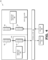
- FIG. 4 is a block diagram of a node 400 that selectively delays packets to support dynamic shared protection along redundant network paths according to some embodiments.
- the node 400 is implemented in some embodiments of the fronthaul network 145 shown in FIG. 1 and the nodes 201-207 in the mesh network 200 shown in FIG. 2 .
- the node 400 includes a data link layer 405 that performs node-to-node data transfer including error detection and correction.
- the node 400 also includes a physical layer 410 that converts digital bits received from the data link layer 405 into electrical, radio, or optical signals for transmission by a transmitter 415.
- the physical layer 410 also converts electrical, radio, or optical signals provided by a receiver 420 into digital bits for processing in the data link layer 405.
- the node 400 includes a client queue 425 that receives and holds packets that are to be transmitted by the node 400.
- the packets are received from an external network or another node in the mesh network that includes the node 400.
- the node 400 also includes an input queue 430 that receives packets from the client queue 425 and delays the packets by a time interval that corresponds to a maximum detection time interval for the mesh network.
- the input queue 430 can be dimensioned to store client traffic received by a time interval equal to a maximum failure detection time for the mesh network.
- Some embodiments of the client queue 425 and the input queue 430 are implemented as first-in-first-out (FIFO) queues.
- Insertion circuitry 435 in the node 400 de-queues packets from the client queue 425.
- One copy of the de-queued packet is provided to the physical layer 410 for transmission via the transmitter 415 via path 438 and another copy of the de-queued packet is provided to the input queue 430.
- the insertion circuitry 435 de-queues packets from the input queue 430 and provides the de-queued packets to the physical layer 410 for transmission via the transmitter 415 in response to detection of a link failure in the mesh network that includes the node 400.
- Some embodiments of the insertion circuitry 435 de-queues a packet from the head of the client queue 425 and sends this packet directly to the physical layer 410.
- the insertion circuitry 435 also provides a copy of the packet to the input queue 430 and adds a fixed latency to each packet that corresponds to the maximum failure detection time.In response to detecting a link failure, the insertion circuitry 435 routes all client packets to the input queue 430 and serves packets from a head of the input queue 430 ( e.g., in FIFO order) without any latency.
- the node 400 On the reception side, the node 400 includes an output queue 440 that receives packets from the physical layer 410 in response to the receiver 420 receiving the packets from an external node or another node in the mesh network.
- the node 400 also includes a client queue 445 that receives packets from the output queue 440.
- Some embodiments of the output queue 440 and the client queue 445 are implemented as FIFO queues.
- Reception circuitry 450 selectively delays packets in the output queue 440 before providing the packets to the client queue 445. Some embodiments of the reception circuitry 450 delay packets by a time interval that is determined based on a maximum propagation delay along a working path as long as no link failure has been detected.
- the reception circuitry 450 delays packets by a time interval that is determined based on a maximum propagation delay along one or more backup paths.
- the reception circuitry 450 de-queues the packets from a head-of-line of the output queue 440 ( e.g., in FIFO order) by adding a fixed latency to each packet. If no link failure has been detected in the mesh networks 200, the fixed latency is equal to a maximum latency for the mesh network 200 minus a sum of the maximum failure detection time and the propagation time for the working path.
- the reception circuitry 450 In response to detecting a link failure into mesh network 200, the reception circuitry 450 changes the fixed latency to a time interval that is equal to the maximum latency minus a sum of the maximum failure detection time and the propagation time for the backup path that is used in the event of the link failure.
- the reception circuitry 450 provides the de-queued packets from the output queue 440 to the client queue 445 after the selected delay time interval.
- Delaying the packets in the queues 425, 430, 440, 445 as discussed herein prevents packet loss in the mesh network during a transition from a working path to a backup path in the event of a link failure. For example, if a link failure is detected in the mesh network 200 at a time t 0 , a backup path k is used to convey packets from the source node to the destination node. The inter-arrival time interval between subsequent arrivals of claim packets is constant and equal to ⁇ p . The last packet that is guaranteed to have been successfully received at the destination node arrived at the insertion circuitry 435 at a time: t 0 ⁇ T fail detection ⁇ ⁇ p
- T fail detection the maximum failure detection time is referred to as T fail detection .
- P - 1 the first packet that is potentially lost due to the link failure arrived at the insertion circuitry 435 at a time: t 0 ⁇ T fail detection
- This packet is referred to as P 0 and the copy of the packet P 0 that is stored in the input queue 430 is provided to the physical layer 410 for transmission.
- the packet P 0 is the head-of-line packet at the input queue 430 since the input queue 430 delays packets by the maximum failure detection time. Arrival and departure times of the packets P -1 , P 0 are summarized in Table 1.
- the input queue 430 and the insertion circuitry 435 delay packets by the time interval: T fail detection
- the packets P -1 , P 0 depart from the reception circuitry in the destination node in sequence, separated by a time interval ⁇ p , with a latency that is equal to T max,latency No packets are lost from the deterministic flow during the switch from the working path to the backup path.
- Delaying the packets in the queues 425, 430, 440, 445 as discussed herein also maintains latency below a maximum latency during the transition from the working path to the backup path.
- Table 2 illustrates the network latencies during nominal operation (without a link failure) and in the event of a failure of the link k.
- the source node receives a packet in a first queue such as the client queue 425 shown in FIG. 4 .
- the source node provides (at block 510) a copy of the packets to a second queue such as the input queue 430 shown in FIG. 4 .
- the packet is selectively forwarded from the first queue or the second queue depending on whether a link failure has been detected in the mesh network.
- insertion circuitry in the node determines whether a link failure has been detected. If not, the method 500 flows to block 520. If a link failure has been detected, the method 500 flows to block 525.
- the packet is provided from the first queue to the physical layer substantially without delay or substantially immediately.
- a transmitter transmits information representative of the packet via a working path through the mesh network.
- the insertion circuitry provides the packet from the second queue to the physical layer in response to detecting the link failure.
- the packet is delayed in the second queue by a time interval corresponding to a maximum failure detection time interval for the mesh network.
- the transmitter transmits information representative of the packet via a backup path through the mesh network.
- FIG. 6 is a flow diagram of a method 600 of selectively delaying packets that are received by a node into a mesh network according to some embodiments.
- the method 600 is implemented in a destination node such as the destination nodes in some embodiments of the fronthaul network 145 shown in FIG. 1 , the nodes 201-207 shown in FIG. 2 , and the node 400 shown in FIG. 4 .
- the destination node receives a packet and stores the packet in the first queue.
- the destination node determines whether a link failure is detected in the mesh network. If not, in which case the packet is received via a working path through the mesh network, the method 600 flows to block 615 and the packet is delayed in the first queue for a time interval that is determined based on a propagation time interval for the working path, as discussed herein. If a link failure has been detected, in which case the packet is received via a backup path through the mesh network, the mesh networks 600 flows to block 620 and the packet is delayed in the first queue for a time interval that is determined based on a propagation time interval for the backup path, as discussed herein. The delayed packets are de-queued from the first queue and provided (at block 625) to a second queue after the appropriate delay time interval.
- certain aspects of the techniques described above may implemented by one or more processors of a processing system executing software.
- the software comprises one or more sets of executable instructions stored or otherwise tangibly embodied on a non-transitory computer readable storage medium.
- the software can include the instructions and certain data that, when executed by the one or more processors, manipulate the one or more processors to perform one or more aspects of the techniques described above.
- the non-transitory computer readable storage medium can include, for example, a magnetic or optical disk storage device, solid state storage devices such as Flash memory, a cache, random access memory (RAM) or other non-volatile memory device or devices, and the like.
- the executable instructions stored on the non-transitory computer readable storage medium may be in source code, assembly language code, object code, or other instruction format that is interpreted or otherwise executable by one or more processors.
- a computer readable storage medium may include any storage medium, or combination of storage media, accessible by a computer system during use to provide instructions and/or data to the computer system.
- Such storage media can include, but is not limited to, optical media (e.g., compact disc (CD), digital versatile disc (DVD), Blu-Ray disc), magnetic media (e.g., floppy disc , magnetic tape, or magnetic hard drive), volatile memory (e.g., random access memory (RAM) or cache), non-volatile memory (e.g., read-only memory (ROM) or Flash memory), or microelectromechanical systems (MEMS)-based storage media.
- optical media e.g., compact disc (CD), digital versatile disc (DVD), Blu-Ray disc
- magnetic media e.g., floppy disc , magnetic tape, or magnetic hard drive
- volatile memory e.g., random access memory (RAM) or cache
- non-volatile memory e.g., read-only memory (ROM) or Flash memory
- MEMS microelect
- circuitry may refer to one or more or all of the following:
- circuitry also covers an implementation of merely a hardware circuit or processor (or multiple processors) or portion of a hardware circuit or processor and its (or their) accompanying software and/or firmware.
- circuitry also covers, for example and if applicable to the particular claim element, a baseband integrated circuit or processor integrated circuit for a mobile device or a similar integrated circuit in a server, a cellular network device, or other computing or network device.
Landscapes
- Engineering & Computer Science (AREA)
- Computer Networks & Wireless Communication (AREA)
- Signal Processing (AREA)
- Theoretical Computer Science (AREA)
- Quality & Reliability (AREA)
- Physics & Mathematics (AREA)
- General Engineering & Computer Science (AREA)
- General Physics & Mathematics (AREA)
- Environmental & Geological Engineering (AREA)
- Data Exchanges In Wide-Area Networks (AREA)
Claims (15)
- Vorrichtung (400), die Folgendes umfasst:eine Übergabeschaltung (435), die dazu ausgelegt ist, erste Pakete vor der Übergabe an ein Maschennetzwerk (200) darauf basierend, ob im Maschennetzwerk (200) ein Fehler detektiert wurde, selektiv um ein erstes Zeitintervall zu verzögern, wobei das erste Zeitintervall einem maximalen Fehlerdetektionszeitintervall für das Maschennetzwerk (200) entspricht; undeine Empfangsschaltung (450), die dazu ausgelegt ist, vom Maschennetzwerk (200) empfangene zweite Pakete in Abhängigkeit davon, ob der Fehler detektiert wurde, selektiv um ein zweites Zeitintervall zu verzögern.
- Vorrichtung (400) nach Anspruch 1, die ferner Folgendes umfasst:eine erste Warteschlange (425), die dazu ausgelegt ist, die ersten Pakete zu speichern; undeine zweite Warteschlange (430), die dazu ausgelegt ist, Kopien der ersten Pakete, die von der ersten Warteschlange (425) empfangen werden, zu speichern, wobei die zweite Warteschlange (430) dazu ausgelegt ist, die Kopien der ersten Pakete um das erste Zeitintervall zu verzögern.
- Vorrichtung (400) nach Anspruch 2, die ferner Folgendes umfasst:
einen Sender (415), der dazu ausgelegt ist, die ersten Pakete zum Maschennetzwerk (200) zu übertragen, wobei die Übergabeschaltung (435) dazu ausgelegt ist, darauf basierend, ob der Fehler im Maschennetzwerk (200) detektiert wurde, dem Sender (415) die ersten Pakete aus der ersten Warteschlange (425) oder die Kopien der ersten Pakete aus der zweiten Warteschlange (430) bereitzustellen. - Vorrichtung (400) nach Anspruch 3, wobei die Übergabeschaltung (435) dazu ausgelegt ist, dem Sender (415) die ersten Pakete aus der ersten Warteschlange (425) bereitzustellen, wenn der Fehler nicht detektiert wurde, und dem Sender (415) in Reaktion auf das Detektieren des Fehlers im Maschennetzwerk (200) die Kopien der ersten Pakete aus der zweiten Warteschlange (430) bereitzustellen.
- Vorrichtung (400) nach Anspruch 4, wobei der Sender (415) dazu ausgelegt ist, die ersten Pakete entlang eines ersten Pfades zu übertragen, wenn der Fehler nicht detektiert wurde, und wobei der Sender (415) dazu ausgelegt ist, in Reaktion auf das Detektieren des Fehlers die ersten Pakete entlang eines zweiten Pfades zu übertragen.
- Vorrichtung (400) nach Anspruch 3, die ferner Folgendes umfasst:
eine dritte Warteschlange (440), die, wenn der Fehler nicht detektiert wurde, dazu ausgelegt ist, die zweiten Pakete via einen dritten Pfad und in Reaktion auf das Detektieren des Fehlers via einen vierten Pfad zu empfangen. - Vorrichtung (400) nach Anspruch 6, wobei die Empfangsschaltung (450), wenn der Fehler nicht detektiert wurde, dazu ausgelegt ist, die zweiten Pakete nach dem zweiten Zeitintervall und in Reaktion auf das Detektieren des Fehlers im Maschennetzwerk (200) nach einem dritten Zeitintervall aus der dritten Warteschlange (440) zu entfernen.
- Vorrichtung (400) nach Anspruch 7, wobei das zweite Zeitintervall auf Basis einer Laufzeit entlang des dritten Pfades bestimmt wird und das dritte Zeitintervall auf Basis einer Laufzeit entlang des vierten Pfades bestimmt wird.
- Vorrichtung (400) nach Anspruch 8, wobei das zweite Zeitintervall gleich einer maximalen Latenz für das Maschennetzwerk (200) minus einer Summe des maximalen Fehlerdetektionszeitintervalls und der Laufzeit entlang des dritten Pfades ist, und wobei das dritte Zeitintervall gleich der maximalen Latenz minus einer Summe des maximalen Fehlerdetektionszeitintervalls und der Laufzeit entlang des vierten Pfades ist.
- Verfahren, das Folgendes umfasst:selektives Verzögern von ersten Paketen vor der Übergabe an ein Maschennetzwerk (200) um ein erstes Zeitintervall darauf basierend, ob im Maschennetzwerk (200) ein Fehler detektiert wurde, wobei das erste Zeitintervall einem maximalen Fehlerdetektionszeitintervall für das Maschennetzwerk (200) entspricht; undselektives Verzögern von vom Maschennetzwerk (200) empfangenen zweiten Paketen um ein zweites Zeitintervall in Abhängigkeit davon, ob der Fehler detektiert wurde.
- Verfahren nach Anspruch 10, das ferner Folgendes umfasst:Speichern der ersten Pakete in einer ersten Warteschlange (425); undSpeichern von Kopien der ersten Pakete, die von der ersten Warteschlange (425) empfangen werden, in einer zweiten Warteschlange (430), wobei die zweite Warteschlange (430) dazu ausgelegt ist, die Kopien der ersten Pakete um das erste Zeitintervall zu verzögern.
- Verfahren nach Anspruch 11, das ferner Folgendes umfasst:selektives Bereitstellen der ersten Pakete aus der ersten Warteschlange (425) oder der zweiten Warteschlange (430) für einen Sender (415) darauf basierend, ob der Fehler im Maschennetzwerk (200) detektiert wurde; undÜbertragen der ersten Pakete oder der Kopien der ersten Pakete durch den Sender (415) zum Maschennetzwerk (200).
- Verfahren nach Anspruch 12, wobei das selektive Bereitstellen der ersten Pakete aus der ersten Warteschlange (425) oder der zweiten Warteschlange (430) das Bereitstellen der ersten Pakete aus der ersten Warteschlange (425) für den Sender (415), wenn der Fehler nicht detektiert wurde, und das Bereitstellen der Kopien der ersten Pakete aus der zweiten Warteschlange (430) für den Sender (415) in Reaktion auf das Detektieren des Fehlers im Maschennetzwerk (200) umfasst.
- Verfahren nach Anspruch 13, wobei das Übertragen der ersten Pakete das Übertragen der ersten Pakete entlang eines ersten Pfades, wenn der Fehler nicht detektiert wurde, und das Übertragen der Kopien der ersten Pakete entlang eines zweiten Pfades in Reaktion auf das Detektieren des Fehlers umfasst.
- Verfahren nach Anspruch 12, das ferner Folgendes umfasst:Empfangen der zweiten Pakete via einen dritten Pfad, wenn der Fehler nicht detektiert wurde, und via einen vierten Pfad in Reaktion auf das Detektieren des Fehlers; undSpeichern der zweiten Pakete in einer dritten Warteschlange (440) .
Applications Claiming Priority (1)
| Application Number | Priority Date | Filing Date | Title |
|---|---|---|---|
| US16/432,783 US10972382B2 (en) | 2019-06-05 | 2019-06-05 | Dynamic shared protection using redundant network paths |
Publications (2)
| Publication Number | Publication Date |
|---|---|
| EP3751806A1 EP3751806A1 (de) | 2020-12-16 |
| EP3751806B1 true EP3751806B1 (de) | 2023-06-07 |
Family
ID=70738281
Family Applications (1)
| Application Number | Title | Priority Date | Filing Date |
|---|---|---|---|
| EP20174807.6A Active EP3751806B1 (de) | 2019-06-05 | 2020-05-14 | Dynamischer gemeinsamer schutz unter verwendung redundanter netzwerkpfade |
Country Status (2)
| Country | Link |
|---|---|
| US (1) | US10972382B2 (de) |
| EP (1) | EP3751806B1 (de) |
Families Citing this family (7)
| Publication number | Priority date | Publication date | Assignee | Title |
|---|---|---|---|---|
| US20230087755A1 (en) * | 2020-03-02 | 2023-03-23 | Nippon Telegraph And Telephone Corporation | Communication system, transmitter, receiver, and communication method and program |
| US11606840B2 (en) * | 2020-03-06 | 2023-03-14 | Hewlett Packard Enterprise Development Lp | Connecting access point to mesh network |
| CN113727220B (zh) * | 2020-05-26 | 2023-04-11 | 华为技术有限公司 | 业务资源预配置方法、设备和系统 |
| US11552872B2 (en) * | 2020-11-23 | 2023-01-10 | Verizon Patent And Licensing Inc. | Systems and methods for automated remote network performance monitoring |
| US12452166B2 (en) * | 2021-10-25 | 2025-10-21 | Ruckus Ip Holdings Llc | Preventing an inter-chassis-link loop using a selective forwarding delay |
| US20260032076A1 (en) * | 2024-07-27 | 2026-01-29 | Avago Technologies International Sales Pte. Limited | Network traffic management system and method for managing packet latency |
| DE102024207952A1 (de) * | 2024-08-21 | 2026-02-26 | Siemens Mobility GmbH | Gemeinsames Ethernet-Netzwerk für verschiedenartige Verfügbarkeitsanforderungen |
Family Cites Families (10)
| Publication number | Priority date | Publication date | Assignee | Title |
|---|---|---|---|---|
| US7660235B2 (en) | 2003-03-20 | 2010-02-09 | Alcatel-Lucent Usa Inc. | Low latency shared data path allocation |
| US7451340B2 (en) * | 2003-03-31 | 2008-11-11 | Lucent Technologies Inc. | Connection set-up extension for restoration path establishment in mesh networks |
| CN101065966A (zh) * | 2004-10-27 | 2007-10-31 | Eg技术有限公司 | 用于从远程位置在有损网络上实时传递视频的网络体系结构 |
| US7606143B2 (en) * | 2007-02-28 | 2009-10-20 | Embarq Corporation | System and method for advanced fail-over for packet label swapping |
| US8027267B2 (en) | 2007-11-06 | 2011-09-27 | Avaya Inc | Network condition capture and reproduction |
| US8891357B2 (en) | 2012-08-31 | 2014-11-18 | Cisco Technology, Inc. | Switching to a protection path without causing packet reordering |
| EP2712099B1 (de) * | 2012-09-19 | 2015-04-01 | Alcatel Lucent | Verfahren zur Verwaltung und Erhaltung einer genauen Zeitverteilung in einem Netzwerk bei Auftreten eines Fehlers |
| JP6650242B2 (ja) * | 2015-10-16 | 2020-02-19 | 日立オートモティブシステムズ株式会社 | 自動運転システム、自動運転制御方法、データecuおよび自動運転ecu |
| US11006331B2 (en) * | 2017-03-24 | 2021-05-11 | Htc Corporation | Device and method of handling pre-allocated uplink grant |
| GB2568315B (en) * | 2017-11-14 | 2020-06-17 | Cambium Networks Ltd | Fault Tolerant Transmission for a Wireless Link |
-
2019
- 2019-06-05 US US16/432,783 patent/US10972382B2/en active Active
-
2020
- 2020-05-14 EP EP20174807.6A patent/EP3751806B1/de active Active
Also Published As
| Publication number | Publication date |
|---|---|
| US10972382B2 (en) | 2021-04-06 |
| EP3751806A1 (de) | 2020-12-16 |
| US20200389386A1 (en) | 2020-12-10 |
Similar Documents
| Publication | Publication Date | Title |
|---|---|---|
| EP3751806B1 (de) | Dynamischer gemeinsamer schutz unter verwendung redundanter netzwerkpfade | |
| US9842013B2 (en) | Dynamic adaptive approach for failure detection of node in a cluster | |
| US11895024B2 (en) | Method, device and computer readable medium for delivering data-plane packets by using separate transport service VNFC | |
| US10439920B2 (en) | Network performance monitoring | |
| GB2574875A (en) | Route selection and QoS support in a wireless access network | |
| EP3977692B1 (de) | Vermeidung von jitter in einem kommunikationssystem | |
| US9560174B2 (en) | Network routing overlay | |
| US11757747B2 (en) | Preventing traffic outages during address resolution protocol (ARP) storms | |
| CN113132043A (zh) | 跨网络运输客户端定时信息 | |
| US9467243B2 (en) | Packet relay device and packet transmission device | |
| CN112543128B (zh) | 用于指示维护模式操作的双向转发检测控制分组 | |
| US8644326B2 (en) | Queue processing method | |
| US12058601B2 (en) | Electronic packet switching based on traffic properties | |
| US20190037536A1 (en) | Point-to-point radio apparatus, mobile backhaul system, and communication control method | |
| EP3886365B1 (de) | Detektion von multihoming-fehlkonfiguration | |
| JP2024519639A (ja) | Integrated Access and Backhaulネットワークにおけるバックホールリンク問題 | |
| EP4412162A1 (de) | Durch steuerungsebene eingeleitete umschaltung für eine teilnehmergruppe | |
| JP6468566B2 (ja) | データ伝送制御システム及び方法、並びに、データ伝送制御プログラム | |
| JP6237111B2 (ja) | 無線通信システム、無線通信方法、基地局、中継装置、及び、移動局 | |
| JP6425290B2 (ja) | 情報送信方法、無線機器コントローラ、無線機器、及び基地局 | |
| US20250063002A1 (en) | Communication system, communication apparatus, communication method, and non-transitory computer-readable medium storing communication program | |
| US20240214907A1 (en) | Communication system, communication control method, and non-transitory computer readable storage medium |
Legal Events
| Date | Code | Title | Description |
|---|---|---|---|
| PUAI | Public reference made under article 153(3) epc to a published international application that has entered the european phase |
Free format text: ORIGINAL CODE: 0009012 |
|
| STAA | Information on the status of an ep patent application or granted ep patent |
Free format text: STATUS: THE APPLICATION HAS BEEN PUBLISHED |
|
| AK | Designated contracting states |
Kind code of ref document: A1 Designated state(s): AL AT BE BG CH CY CZ DE DK EE ES FI FR GB GR HR HU IE IS IT LI LT LU LV MC MK MT NL NO PL PT RO RS SE SI SK SM TR |
|
| AX | Request for extension of the european patent |
Extension state: BA ME |
|
| STAA | Information on the status of an ep patent application or granted ep patent |
Free format text: STATUS: REQUEST FOR EXAMINATION WAS MADE |
|
| 17P | Request for examination filed |
Effective date: 20210616 |
|
| RBV | Designated contracting states (corrected) |
Designated state(s): AL AT BE BG CH CY CZ DE DK EE ES FI FR GB GR HR HU IE IS IT LI LT LU LV MC MK MT NL NO PL PT RO RS SE SI SK SM TR |
|
| REG | Reference to a national code |
Ref country code: DE Ref legal event code: R079 Ref document number: 602020011547 Country of ref document: DE Free format text: PREVIOUS MAIN CLASS: H04L0012823000 Ipc: H04L0047320000 |
|
| RIC1 | Information provided on ipc code assigned before grant |
Ipc: G06F 11/20 20060101ALI20221104BHEP Ipc: H04L 45/28 20220101ALI20221104BHEP Ipc: H04L 45/00 20220101ALI20221104BHEP Ipc: H04L 47/32 20220101AFI20221104BHEP |
|
| GRAP | Despatch of communication of intention to grant a patent |
Free format text: ORIGINAL CODE: EPIDOSNIGR1 |
|
| STAA | Information on the status of an ep patent application or granted ep patent |
Free format text: STATUS: GRANT OF PATENT IS INTENDED |
|
| INTG | Intention to grant announced |
Effective date: 20221220 |
|
| GRAS | Grant fee paid |
Free format text: ORIGINAL CODE: EPIDOSNIGR3 |
|
| GRAA | (expected) grant |
Free format text: ORIGINAL CODE: 0009210 |
|
| STAA | Information on the status of an ep patent application or granted ep patent |
Free format text: STATUS: THE PATENT HAS BEEN GRANTED |
|
| AK | Designated contracting states |
Kind code of ref document: B1 Designated state(s): AL AT BE BG CH CY CZ DE DK EE ES FI FR GB GR HR HU IE IS IT LI LT LU LV MC MK MT NL NO PL PT RO RS SE SI SK SM TR |
|
| REG | Reference to a national code |
Ref country code: GB Ref legal event code: FG4D |
|
| REG | Reference to a national code |
Ref country code: CH Ref legal event code: EP Ref country code: AT Ref legal event code: REF Ref document number: 1578126 Country of ref document: AT Kind code of ref document: T Effective date: 20230615 Ref country code: DE Ref legal event code: R096 Ref document number: 602020011547 Country of ref document: DE |
|
| REG | Reference to a national code |
Ref country code: LT Ref legal event code: MG9D |
|
| REG | Reference to a national code |
Ref country code: NL Ref legal event code: MP Effective date: 20230607 |
|
| PG25 | Lapsed in a contracting state [announced via postgrant information from national office to epo] |
Ref country code: SE Free format text: LAPSE BECAUSE OF FAILURE TO SUBMIT A TRANSLATION OF THE DESCRIPTION OR TO PAY THE FEE WITHIN THE PRESCRIBED TIME-LIMIT Effective date: 20230607 Ref country code: NO Free format text: LAPSE BECAUSE OF FAILURE TO SUBMIT A TRANSLATION OF THE DESCRIPTION OR TO PAY THE FEE WITHIN THE PRESCRIBED TIME-LIMIT Effective date: 20230907 Ref country code: ES Free format text: LAPSE BECAUSE OF FAILURE TO SUBMIT A TRANSLATION OF THE DESCRIPTION OR TO PAY THE FEE WITHIN THE PRESCRIBED TIME-LIMIT Effective date: 20230607 |
|
| REG | Reference to a national code |
Ref country code: AT Ref legal event code: MK05 Ref document number: 1578126 Country of ref document: AT Kind code of ref document: T Effective date: 20230607 |
|
| PG25 | Lapsed in a contracting state [announced via postgrant information from national office to epo] |
Ref country code: RS Free format text: LAPSE BECAUSE OF FAILURE TO SUBMIT A TRANSLATION OF THE DESCRIPTION OR TO PAY THE FEE WITHIN THE PRESCRIBED TIME-LIMIT Effective date: 20230607 Ref country code: NL Free format text: LAPSE BECAUSE OF FAILURE TO SUBMIT A TRANSLATION OF THE DESCRIPTION OR TO PAY THE FEE WITHIN THE PRESCRIBED TIME-LIMIT Effective date: 20230607 Ref country code: LV Free format text: LAPSE BECAUSE OF FAILURE TO SUBMIT A TRANSLATION OF THE DESCRIPTION OR TO PAY THE FEE WITHIN THE PRESCRIBED TIME-LIMIT Effective date: 20230607 Ref country code: LT Free format text: LAPSE BECAUSE OF FAILURE TO SUBMIT A TRANSLATION OF THE DESCRIPTION OR TO PAY THE FEE WITHIN THE PRESCRIBED TIME-LIMIT Effective date: 20230607 Ref country code: HR Free format text: LAPSE BECAUSE OF FAILURE TO SUBMIT A TRANSLATION OF THE DESCRIPTION OR TO PAY THE FEE WITHIN THE PRESCRIBED TIME-LIMIT Effective date: 20230607 Ref country code: GR Free format text: LAPSE BECAUSE OF FAILURE TO SUBMIT A TRANSLATION OF THE DESCRIPTION OR TO PAY THE FEE WITHIN THE PRESCRIBED TIME-LIMIT Effective date: 20230908 |
|
| PG25 | Lapsed in a contracting state [announced via postgrant information from national office to epo] |
Ref country code: FI Free format text: LAPSE BECAUSE OF FAILURE TO SUBMIT A TRANSLATION OF THE DESCRIPTION OR TO PAY THE FEE WITHIN THE PRESCRIBED TIME-LIMIT Effective date: 20230607 |
|
| PG25 | Lapsed in a contracting state [announced via postgrant information from national office to epo] |
Ref country code: SK Free format text: LAPSE BECAUSE OF FAILURE TO SUBMIT A TRANSLATION OF THE DESCRIPTION OR TO PAY THE FEE WITHIN THE PRESCRIBED TIME-LIMIT Effective date: 20230607 |
|
| PG25 | Lapsed in a contracting state [announced via postgrant information from national office to epo] |
Ref country code: IS Free format text: LAPSE BECAUSE OF FAILURE TO SUBMIT A TRANSLATION OF THE DESCRIPTION OR TO PAY THE FEE WITHIN THE PRESCRIBED TIME-LIMIT Effective date: 20231007 |
|
| PG25 | Lapsed in a contracting state [announced via postgrant information from national office to epo] |
Ref country code: SM Free format text: LAPSE BECAUSE OF FAILURE TO SUBMIT A TRANSLATION OF THE DESCRIPTION OR TO PAY THE FEE WITHIN THE PRESCRIBED TIME-LIMIT Effective date: 20230607 Ref country code: SK Free format text: LAPSE BECAUSE OF FAILURE TO SUBMIT A TRANSLATION OF THE DESCRIPTION OR TO PAY THE FEE WITHIN THE PRESCRIBED TIME-LIMIT Effective date: 20230607 Ref country code: RO Free format text: LAPSE BECAUSE OF FAILURE TO SUBMIT A TRANSLATION OF THE DESCRIPTION OR TO PAY THE FEE WITHIN THE PRESCRIBED TIME-LIMIT Effective date: 20230607 Ref country code: PT Free format text: LAPSE BECAUSE OF FAILURE TO SUBMIT A TRANSLATION OF THE DESCRIPTION OR TO PAY THE FEE WITHIN THE PRESCRIBED TIME-LIMIT Effective date: 20231009 Ref country code: IS Free format text: LAPSE BECAUSE OF FAILURE TO SUBMIT A TRANSLATION OF THE DESCRIPTION OR TO PAY THE FEE WITHIN THE PRESCRIBED TIME-LIMIT Effective date: 20231007 Ref country code: EE Free format text: LAPSE BECAUSE OF FAILURE TO SUBMIT A TRANSLATION OF THE DESCRIPTION OR TO PAY THE FEE WITHIN THE PRESCRIBED TIME-LIMIT Effective date: 20230607 Ref country code: CZ Free format text: LAPSE BECAUSE OF FAILURE TO SUBMIT A TRANSLATION OF THE DESCRIPTION OR TO PAY THE FEE WITHIN THE PRESCRIBED TIME-LIMIT Effective date: 20230607 Ref country code: AT Free format text: LAPSE BECAUSE OF FAILURE TO SUBMIT A TRANSLATION OF THE DESCRIPTION OR TO PAY THE FEE WITHIN THE PRESCRIBED TIME-LIMIT Effective date: 20230607 |
|
| PG25 | Lapsed in a contracting state [announced via postgrant information from national office to epo] |
Ref country code: PL Free format text: LAPSE BECAUSE OF FAILURE TO SUBMIT A TRANSLATION OF THE DESCRIPTION OR TO PAY THE FEE WITHIN THE PRESCRIBED TIME-LIMIT Effective date: 20230607 |
|
| REG | Reference to a national code |
Ref country code: DE Ref legal event code: R097 Ref document number: 602020011547 Country of ref document: DE |
|
| PLBE | No opposition filed within time limit |
Free format text: ORIGINAL CODE: 0009261 |
|
| STAA | Information on the status of an ep patent application or granted ep patent |
Free format text: STATUS: NO OPPOSITION FILED WITHIN TIME LIMIT |
|
| PG25 | Lapsed in a contracting state [announced via postgrant information from national office to epo] |
Ref country code: DK Free format text: LAPSE BECAUSE OF FAILURE TO SUBMIT A TRANSLATION OF THE DESCRIPTION OR TO PAY THE FEE WITHIN THE PRESCRIBED TIME-LIMIT Effective date: 20230607 |
|
| PG25 | Lapsed in a contracting state [announced via postgrant information from national office to epo] |
Ref country code: SI Free format text: LAPSE BECAUSE OF FAILURE TO SUBMIT A TRANSLATION OF THE DESCRIPTION OR TO PAY THE FEE WITHIN THE PRESCRIBED TIME-LIMIT Effective date: 20230607 |
|
| 26N | No opposition filed |
Effective date: 20240308 |
|
| PG25 | Lapsed in a contracting state [announced via postgrant information from national office to epo] |
Ref country code: SI Free format text: LAPSE BECAUSE OF FAILURE TO SUBMIT A TRANSLATION OF THE DESCRIPTION OR TO PAY THE FEE WITHIN THE PRESCRIBED TIME-LIMIT Effective date: 20230607 Ref country code: IT Free format text: LAPSE BECAUSE OF FAILURE TO SUBMIT A TRANSLATION OF THE DESCRIPTION OR TO PAY THE FEE WITHIN THE PRESCRIBED TIME-LIMIT Effective date: 20230607 |
|
| PG25 | Lapsed in a contracting state [announced via postgrant information from national office to epo] |
Ref country code: BG Free format text: LAPSE BECAUSE OF FAILURE TO SUBMIT A TRANSLATION OF THE DESCRIPTION OR TO PAY THE FEE WITHIN THE PRESCRIBED TIME-LIMIT Effective date: 20230607 |
|
| PG25 | Lapsed in a contracting state [announced via postgrant information from national office to epo] |
Ref country code: BG Free format text: LAPSE BECAUSE OF FAILURE TO SUBMIT A TRANSLATION OF THE DESCRIPTION OR TO PAY THE FEE WITHIN THE PRESCRIBED TIME-LIMIT Effective date: 20230607 |
|
| REG | Reference to a national code |
Ref country code: CH Ref legal event code: PL |
|
| PG25 | Lapsed in a contracting state [announced via postgrant information from national office to epo] |
Ref country code: MC Free format text: LAPSE BECAUSE OF FAILURE TO SUBMIT A TRANSLATION OF THE DESCRIPTION OR TO PAY THE FEE WITHIN THE PRESCRIBED TIME-LIMIT Effective date: 20230607 |
|
| PG25 | Lapsed in a contracting state [announced via postgrant information from national office to epo] |
Ref country code: LU Free format text: LAPSE BECAUSE OF NON-PAYMENT OF DUE FEES Effective date: 20240514 |
|
| PG25 | Lapsed in a contracting state [announced via postgrant information from national office to epo] |
Ref country code: MC Free format text: LAPSE BECAUSE OF FAILURE TO SUBMIT A TRANSLATION OF THE DESCRIPTION OR TO PAY THE FEE WITHIN THE PRESCRIBED TIME-LIMIT Effective date: 20230607 Ref country code: LU Free format text: LAPSE BECAUSE OF NON-PAYMENT OF DUE FEES Effective date: 20240514 Ref country code: CH Free format text: LAPSE BECAUSE OF NON-PAYMENT OF DUE FEES Effective date: 20240531 |
|
| REG | Reference to a national code |
Ref country code: BE Ref legal event code: MM Effective date: 20240531 |
|
| PG25 | Lapsed in a contracting state [announced via postgrant information from national office to epo] |
Ref country code: IE Free format text: LAPSE BECAUSE OF NON-PAYMENT OF DUE FEES Effective date: 20240514 |
|
| PG25 | Lapsed in a contracting state [announced via postgrant information from national office to epo] |
Ref country code: BE Free format text: LAPSE BECAUSE OF NON-PAYMENT OF DUE FEES Effective date: 20240531 |
|
| PG25 | Lapsed in a contracting state [announced via postgrant information from national office to epo] |
Ref country code: FR Free format text: LAPSE BECAUSE OF NON-PAYMENT OF DUE FEES Effective date: 20240531 |
|
| PGFP | Annual fee paid to national office [announced via postgrant information from national office to epo] |
Ref country code: DE Payment date: 20250402 Year of fee payment: 6 |
|
| PGFP | Annual fee paid to national office [announced via postgrant information from national office to epo] |
Ref country code: GB Payment date: 20250401 Year of fee payment: 6 |
|
| PG25 | Lapsed in a contracting state [announced via postgrant information from national office to epo] |
Ref country code: CY Free format text: LAPSE BECAUSE OF FAILURE TO SUBMIT A TRANSLATION OF THE DESCRIPTION OR TO PAY THE FEE WITHIN THE PRESCRIBED TIME-LIMIT; INVALID AB INITIO Effective date: 20200514 |
|
| PG25 | Lapsed in a contracting state [announced via postgrant information from national office to epo] |
Ref country code: HU Free format text: LAPSE BECAUSE OF FAILURE TO SUBMIT A TRANSLATION OF THE DESCRIPTION OR TO PAY THE FEE WITHIN THE PRESCRIBED TIME-LIMIT; INVALID AB INITIO Effective date: 20200514 |