EP3751729B1 - Champ solaire avec centrale solaire de référence pour une gestion améliorée - Google Patents
Champ solaire avec centrale solaire de référence pour une gestion améliorée Download PDFInfo
- Publication number
- EP3751729B1 EP3751729B1 EP20179934.3A EP20179934A EP3751729B1 EP 3751729 B1 EP3751729 B1 EP 3751729B1 EP 20179934 A EP20179934 A EP 20179934A EP 3751729 B1 EP3751729 B1 EP 3751729B1
- Authority
- EP
- European Patent Office
- Prior art keywords
- solar
- orientation
- modules
- cor
- module
- Prior art date
- Legal status (The legal status is an assumption and is not a legal conclusion. Google has not performed a legal analysis and makes no representation as to the accuracy of the status listed.)
- Active
Links
Images
Classifications
-
- H—ELECTRICITY
- H02—GENERATION; CONVERSION OR DISTRIBUTION OF ELECTRIC POWER
- H02S—GENERATION OF ELECTRIC POWER BY CONVERSION OF INFRARED RADIATION, VISIBLE LIGHT OR ULTRAVIOLET LIGHT, e.g. USING PHOTOVOLTAIC [PV] MODULES
- H02S20/00—Supporting structures for PV modules
- H02S20/30—Supporting structures being movable or adjustable, e.g. for angle adjustment
- H02S20/32—Supporting structures being movable or adjustable, e.g. for angle adjustment specially adapted for solar tracking
-
- F—MECHANICAL ENGINEERING; LIGHTING; HEATING; WEAPONS; BLASTING
- F24—HEATING; RANGES; VENTILATING
- F24S—SOLAR HEAT COLLECTORS; SOLAR HEAT SYSTEMS
- F24S50/00—Arrangements for controlling solar heat collectors
- F24S50/20—Arrangements for controlling solar heat collectors for tracking
-
- G—PHYSICS
- G05—CONTROLLING; REGULATING
- G05D—SYSTEMS FOR CONTROLLING OR REGULATING NON-ELECTRIC VARIABLES
- G05D3/00—Control of position or direction
- G05D3/10—Control of position or direction without using feedback
- G05D3/105—Solar tracker
-
- F—MECHANICAL ENGINEERING; LIGHTING; HEATING; WEAPONS; BLASTING
- F24—HEATING; RANGES; VENTILATING
- F24S—SOLAR HEAT COLLECTORS; SOLAR HEAT SYSTEMS
- F24S50/00—Arrangements for controlling solar heat collectors
- F24S50/20—Arrangements for controlling solar heat collectors for tracking
- F24S2050/25—Calibration means; Methods for initial positioning of solar concentrators or solar receivers
-
- F—MECHANICAL ENGINEERING; LIGHTING; HEATING; WEAPONS; BLASTING
- F24—HEATING; RANGES; VENTILATING
- F24S—SOLAR HEAT COLLECTORS; SOLAR HEAT SYSTEMS
- F24S30/00—Arrangements for moving or orienting solar heat collector modules
- F24S30/40—Arrangements for moving or orienting solar heat collector modules for rotary movement
- F24S30/42—Arrangements for moving or orienting solar heat collector modules for rotary movement with only one rotation axis
- F24S30/425—Horizontal axis
-
- Y—GENERAL TAGGING OF NEW TECHNOLOGICAL DEVELOPMENTS; GENERAL TAGGING OF CROSS-SECTIONAL TECHNOLOGIES SPANNING OVER SEVERAL SECTIONS OF THE IPC; TECHNICAL SUBJECTS COVERED BY FORMER USPC CROSS-REFERENCE ART COLLECTIONS [XRACs] AND DIGESTS
- Y02—TECHNOLOGIES OR APPLICATIONS FOR MITIGATION OR ADAPTATION AGAINST CLIMATE CHANGE
- Y02B—CLIMATE CHANGE MITIGATION TECHNOLOGIES RELATED TO BUILDINGS, e.g. HOUSING, HOUSE APPLIANCES OR RELATED END-USER APPLICATIONS
- Y02B10/00—Integration of renewable energy sources in buildings
- Y02B10/10—Photovoltaic [PV]
-
- Y—GENERAL TAGGING OF NEW TECHNOLOGICAL DEVELOPMENTS; GENERAL TAGGING OF CROSS-SECTIONAL TECHNOLOGIES SPANNING OVER SEVERAL SECTIONS OF THE IPC; TECHNICAL SUBJECTS COVERED BY FORMER USPC CROSS-REFERENCE ART COLLECTIONS [XRACs] AND DIGESTS
- Y02—TECHNOLOGIES OR APPLICATIONS FOR MITIGATION OR ADAPTATION AGAINST CLIMATE CHANGE
- Y02E—REDUCTION OF GREENHOUSE GAS [GHG] EMISSIONS, RELATED TO ENERGY GENERATION, TRANSMISSION OR DISTRIBUTION
- Y02E10/00—Energy generation through renewable energy sources
- Y02E10/40—Solar thermal energy, e.g. solar towers
- Y02E10/47—Mountings or tracking
-
- Y—GENERAL TAGGING OF NEW TECHNOLOGICAL DEVELOPMENTS; GENERAL TAGGING OF CROSS-SECTIONAL TECHNOLOGIES SPANNING OVER SEVERAL SECTIONS OF THE IPC; TECHNICAL SUBJECTS COVERED BY FORMER USPC CROSS-REFERENCE ART COLLECTIONS [XRACs] AND DIGESTS
- Y02—TECHNOLOGIES OR APPLICATIONS FOR MITIGATION OR ADAPTATION AGAINST CLIMATE CHANGE
- Y02E—REDUCTION OF GREENHOUSE GAS [GHG] EMISSIONS, RELATED TO ENERGY GENERATION, TRANSMISSION OR DISTRIBUTION
- Y02E10/00—Energy generation through renewable energy sources
- Y02E10/50—Photovoltaic [PV] energy
Definitions
- the present invention relates to a solar field comprising a plurality of solar modules distributed in several parallel rows, as well as to a method for managing such a solar field.
- each solar module comprises at least one solar collector, in particular of the photovoltaic panel type, carried by a single-axis solar tracker, where each solar tracker is controlled in rotation around a main axis. by means of an actuator for a rotation of the solar module making it possible to follow the sun during its elevation and its descent from east to west.
- the invention therefore relates to the field of solar fields comprising solar trackers, otherwise known as tracker support systems or "solar tracker”, distributed in parallel rows and supporting solar collectors, where the solar trackers are of the single-axis type, that is that is to say, orientable according to a single principal axis, for a rotation making it possible to follow the sun during its elevation and its descent from east to west.
- solar trackers otherwise known as tracker support systems or "solar tracker”
- the solar trackers are of the single-axis type, that is that is to say, orientable according to a single principal axis, for a rotation making it possible to follow the sun during its elevation and its descent from east to west.
- a main axis generally extends horizontally and substantially parallel to the ground on which the solar tracker is anchored.
- the solar trackers are aligned, with their main axes substantially coincident, generally in a north-south direction.
- This common orientation setpoint is generally established on the basis of an astronomical calculation of the position of the sun, for real-time positioning opposite the sun, possibly with phases of horizontal flattening of the solar collectors, at the start and end of the day.
- This common orientation instruction depends in particular on the date, because the position of the sun varies from one day to another over the seasons.
- Diffuse solar radiation occurs when direct solar radiation scatters through clouds and atmospheric particles. Diffuse solar radiation results from the diffraction of light by clouds and various molecules suspended in the atmosphere. Diffuse solar radiation therefore does not necessarily follow the direction defined by the sun towards the observation point on the surface of the Earth. Consequently, in cloudy conditions, it may be preferable, in order to obtain maximum efficiency with regard to these conditions, to orient the solar trackers or modules on a so-called indirect or diffuse orientation which does not necessarily correspond to the direction of the solar radiation. direct.
- the solar collector can be of the double-sided type, that is to say with a productive upper face facing the sun and an equally productive lower face facing the ground.
- the lower face receives the solar radiation reflected by the ground, generally called albedo.
- albedo it may be preferable, in order to obtain maximum efficiency, to orient the solar trackers or modules on a so-called indirect orientation which does not necessarily correspond to the direction of the direct solar radiation.
- US 2013/056614 A1 describes a solar array comprising a plurality of solar trackers having drive units configured to independently calibrate each solar tracker multiple times per day.
- GB 2 467 197 A discloses a plurality of solar modules distributed in several parallel rows, each solar module comprising at least one solar collector, in particular of the photovoltaic panel type, carried by a single-axis solar tracker, where each solar tracker is controlled in rotation around a main axis at the means of an actuator for rotation of the solar module making it possible to follow the sun during its elevation and its descent from east to west, said solar field further comprising a unit for controlling the angular orientation of the solar modules, said control unit being connected to the actuators to control the angular orientation of the solar modules by applying an orientation instruction common to all the solar modules
- the present invention aims to solve these drawbacks by proposing a solar field, and an associated management method, which make it possible to enslave the solar modules on a common orientation setpoint which will take into account, at least partially, the diffuse radiation and/or albedo
- the reference solar power plant will make it possible to test an initial orientation setpoint (for example a direct solar radiation monitoring setpoint) and at least one secondary reference orientation setpoint (advantageously several secondary reference orientation setpoints ) offset angularly with respect to the initial orientation setpoint by an offset angle.
- an initial orientation setpoint for example a direct solar radiation monitoring setpoint
- at least one secondary reference orientation setpoint for example several secondary reference orientation setpoints
- an offset angle shift may prove to offer better production of solar energy
- the reference solar power plant will make it possible to note that a secondary reference orientation setpoint associated with an offset angle is to be preferred, and therefore the unit of control will implement an offset angle shift for all solar modules, except solar modules reference lenses. The more secondary reference solar modules there are, the more it will be possible to test different offset angles.
- This solution is particularly simple and inexpensive to implement, while providing an improvement in the overall solar energy production of the solar field, because it directly takes into account the solar energy production for one or more offset angles. around the initial orientation instruction.
- the reference solar power plant comprises several secondary reference solar modules each associated with a dedicated offset angle.
- the reference solar power plant comprises a number N of secondary reference solar modules associated with positive offset angles and a number M of secondary reference solar modules associated with negative offset angles, where N and M are integers.
- At least one difference between two neighboring offset angles is less than 3 degrees in absolute value; one of these two offset angles being able to correspond to the zero offset angle of the central reference solar module.
- the angular offset between the orientation setpoints of at least two neighboring reference solar modules does not exceed 3 degrees, which is sufficient to test different offset angles.
- the solar field comprises, at the input of the control unit, a unit for calculating the initial orientation instruction as a function of an astronomical calculation of the position of the sun.
- the calculation unit prefferably configured to calculate the initial orientation setpoint as a function of at least one of the following parameters: minimum and maximum orientations accessible for the solar trackers, shading of the solar modules of a row on the solar modules of an adjacent row.
- control unit is shaped to control the angular orientation of the solar modules, with the exception of the reference solar modules, by applying as common orientation setpoint the secondary orientation setpoint applied to a secondary reference solar module exhibiting the greatest solar energy production value, only if this secondary reference solar module exhibits the greatest solar energy production value during a predefined waiting period.
- each change of orientation solicits at least one actuator (generally an electric motor), generating electrical consumption and wear of the mechanical components requested by the change of orientation (bearings, rotating guide elements, etc.) .
- This electrical consumption and this wear will not necessarily be offset by the productivity gains obtained by sticking to the secondary orientation instructions.
- the method implements the control of the angular orientation of the solar modules, with the exception of the reference solar modules, by applying as common orientation setpoint said secondary reference orientation setpoint, only if this secondary reference solar module has the greatest production value of solar energy for a preset waiting time.
- the present invention also relates to the characteristic according to which the initial orientation instruction is calculated according to an astronomical calculation of the position of the sun.
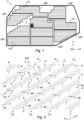
- FIG 1 illustrates a solar field 1 in accordance with the invention, comprising several groups GR of several rows 10 of solar modules (these solar modules not being illustrated on the figure 1 and visible on the figure 2 ), these groups GR and these rows 10 being distributed and dimensioned according to the morphology of the terrain which hosts the solar field 1.
- the solar field 1 also comprises a reference solar power station 2 described later.
- each row 10 comprises several solar modules 3 aligned in the north-south direction and arranged side by side within the row 10.
- Each solar tracker 3 is controlled in rotation around its main axis A by means of an actuator (not shown) for rotation of the solar module 3 making it possible to follow the sun during its elevation and its descent from east to west.
- This actuator can be specific to each solar module 3, or can be shared between several solar modules 3, for example within the same row 10, or even two or more rows 10.
- Each solar module 3 further comprises at least one solar collector 5, and in particular one or more photovoltaic panels, supported by or mounted on the mobile structure of the solar tracker 4.
- the solar collectors are photovoltaic panels 5 .
- the axis of rotation A is substantially horizontal and directed in the north-south direction.
- the photovoltaic panel(s) 5 are horizontal, extending along a horizontal plane defined by a longitudinal axis X (parallel to the main axis A) along the north-south direction and by a transverse axis Y along the east-west direction, orthogonal to a vertical Z axis.
- the angular orientation, otherwise called angle of inclination, of a solar module 3 corresponds to the angle of the normal to (x) photovoltaic panel(s) 5 with respect to the vertical axis Z taken in a horizontal plane (X, Y).
- this angular orientation is 0 degrees.
- the solar field 1 further comprises a calculation unit 6 able to calculate an initial orientation instruction COI according to an astronomical calculation of the position of the sun.
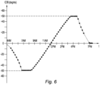
- FIG. 6 illustrates an example of variation of the initial orientation instruction COI as a function of time t, on a given date, over a hourly amplitude of a day taken between 4 o'clock in the morning (4 AM) and seven o'clock in the evening (7 PM). It should be noted that this variation presents stages at - 50 degrees in the morning and at + 50 degrees in the afternoon, corresponding to the maximum and minimum orientations of the solar module 3, because the rotation of the solar module 3 is limited for mechanical reasons. .
- This initial orientation setpoint COI can also be calculated according to other parameters, such as for example an optimization taking into account the shading phenomena of the solar modules 3 of a row 10 on the solar modules 3 of a row 10 adjacent.
- the solar field 1 also comprises a control unit 7 capable of controlling the angular orientation of the solar modules 3 of the rows 10 of the groups GR, this control unit 7 being connected to the actuators of these solar modules 3 to control their angular orientations in applying a common COC orientation instruction to all these solar modules 3.
- This control unit 7 is connected at the input to the calculation unit 6 in order to receive as input data the initial orientation instruction COI and is connected at the output to these solar modules 3 (and more specifically to their actuators) in order to to output the common orientation instruction COC which will be applied to all the solar modules 3.
- This control unit 7 is also connected to the reference solar power plant 2 to establish this common orientation setpoint COC according to the initial orientation setpoint COI and also according to a response from this reference solar power plant 2.
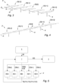
- the reference solar power plant 2 comprises several reference solar modules 20(i) (i relative integer), including a central reference solar module 20(0) and several secondary reference solar modules 20(j) (j relative integer not no).
- the reference solar power plant 2 comprises two pairs of secondary reference solar modules, namely a first pair of secondary reference solar modules 21(+1), 21(-1), and a second pair of secondary reference solar modules 21 (+2), 21 (-2).
- the reference solar modules 20(i) are of the same type as the solar modules 3 described previously, but they may optionally have different dimensions.
- the reference solar modules 20(i) thus comprise a follower support 4 mobile in rotation along an axis main A and supporting at least one solar collector 5 of the same technology as the solar collectors 5 of the solar modules 3.
- these reference solar modules 20(i) can for example be aligned orthogonally to their main axes A of rotation (as visible on the picture 3 ), or be aligned along their main axes A of rotation.
- control unit 7 controls the angular orientation of the central reference solar module 20(0) so that it follows the curve of the initial orientation instruction COI.
- control unit 7 controls the angular orientation of each secondary reference solar module 20(j) so that it follows the curve of the initial orientation instruction COI shifted by the offset angle OFF (j) dedicated to the secondary reference solar module 20(j).
- a secondary reference module 21(+1) (respectively 21(+ 2)) is associated with a positive offset angle OFF(+1) (respectively OFF(+2)) and the other secondary reference module 21(-1) (respectively 21(-2)) is associated with a offset angle OFF(-1) (respectively OFF(-2)) negative.
- OFF(-1) and OFF(+1) are equal in absolute value.
- the positive offset angle (+Ak) and the negative offset angle (-Ak) of each pair of secondary reference solar modules 20(+k), 20(-k) are equal in value absolute.
- the offset angles of smallest absolute value that is to say the offset angles OFF(+1) and OFF(-1), are less than or equal to 3 degrees in absolute value.
- A1 ⁇ 3 degrees.
- the difference between two neighboring offset angles is less than or equal to 3 degrees in absolute value.
- the number of secondary reference solar modules 21(j) and the choice of their offset angles OFF(j) depends in particular on the host site of the solar field 1 (configuration, environment such as presence hills, mountains, bodies of water, etc.) and solar collector technology 5.
- control unit 7 controls the angular orientation of the solar modules 3 by applying as common orientation setpoint the reference orientation setpoint COR(i) associated with the reference solar module 20(i) having the greatest solar energy production value P(i).
- the control unit 7 implements the controlling the angular orientation of the solar modules 3 by applying as common orientation setpoint COC said secondary reference orientation setpoint COR(j), only if this secondary reference solar module 20(j) has the greatest value of production of solar energy P(j) for a predefined waiting period DAT.
- the reference solar power plant 2 makes it possible to detect that an angle of offset OFF(j) applied with respect to the COI initial orientation instruction, will provide an increase in the production of solar energy, and the control unit 7 will report this offset angle OFF(j) to all of the solar modules 3 in order to increase the electrical production of the solar field 1.
- the reference solar power plant comprises several secondary reference solar modules (20(j)) each associated with a dedicated offset angle (OFF(j)).
- the reference solar power plant (2) comprises a number N of secondary reference solar modules (20(j)) associated with positive offset angles (OFF(j)) and a number M of solar modules secondary reference (20(j)) associated with negative offset OFF(j) angles, where N and M are integers.
- the difference (PA) between two neighboring offset angles (OFF(i)) is less than or equal to 3 degrees in absolute value.
- the solar field (1) comprises at the input of the control unit (7), a calculation unit (6) of the initial orientation setpoint (COI) according to an astronomical calculation of the position of the sun.
- COI initial orientation setpoint
- the calculation unit (6) is shaped to calculate the initial orientation setpoint (COI) as a function of at least one of the following parameters: minimum and maximum orientations accessible for the solar trackers, shading of the solar modules of one row on the solar modules of an adjacent row.
- COI initial orientation setpoint
- control unit (7) is shaped to control the angular orientation of the solar modules (3), with the exception of the reference solar modules (20(i)), by applying as a setpoint common orientation (COC) the secondary orientation setpoint (COR(j)) applied to a secondary reference solar module (20(j)) having the highest solar energy production value (P(j)), only if this secondary reference solar module (20(j)) has the highest solar energy production value (P(j)) during a predefined waiting time (DAT).
- COC setpoint common orientation
- COR(j) secondary orientation setpoint
- the method implements the control of the angular orientation of the solar modules (3), with the exception of the reference solar modules (20(i)), by applying as common orientation instruction (COC) said secondary reference orientation setpoint (COR(j)), only if this secondary reference solar module (20(j)) has the highest solar energy production value (P(j)) during a predefined waiting time.
- COC common orientation instruction
- the initial orientation instruction (COI) is calculated according to an astronomical calculation of the position of the sun.
Landscapes
- Engineering & Computer Science (AREA)
- Life Sciences & Earth Sciences (AREA)
- Sustainable Development (AREA)
- Physics & Mathematics (AREA)
- Chemical & Material Sciences (AREA)
- Thermal Sciences (AREA)
- Sustainable Energy (AREA)
- Combustion & Propulsion (AREA)
- Mechanical Engineering (AREA)
- General Engineering & Computer Science (AREA)
- General Physics & Mathematics (AREA)
- Automation & Control Theory (AREA)
- Photovoltaic Devices (AREA)
- Control Of Electrical Variables (AREA)
Priority Applications (1)
| Application Number | Priority Date | Filing Date | Title |
|---|---|---|---|
| EP23181375.9A EP4242550B1 (fr) | 2016-01-04 | 2016-12-27 | Champ solaire avec centrale solaire de référence pour une gestion améliorée |
Applications Claiming Priority (3)
| Application Number | Priority Date | Filing Date | Title |
|---|---|---|---|
| FR1650014A FR3046509B1 (fr) | 2016-01-04 | 2016-01-04 | Champ solaire avec centrale solaire de reference pour une gestion amelioree |
| PCT/FR2016/053672 WO2017118796A1 (fr) | 2016-01-04 | 2016-12-27 | Champ solaire avec centrale solaire de référence pour une gestion améliorée |
| EP16829292.8A EP3400648B1 (fr) | 2016-01-04 | 2016-12-27 | Champ solaire avec centrale solaire de référence pour une gestion améliorée |
Related Parent Applications (1)
| Application Number | Title | Priority Date | Filing Date |
|---|---|---|---|
| EP16829292.8A Division EP3400648B1 (fr) | 2016-01-04 | 2016-12-27 | Champ solaire avec centrale solaire de référence pour une gestion améliorée |
Related Child Applications (1)
| Application Number | Title | Priority Date | Filing Date |
|---|---|---|---|
| EP23181375.9A Division EP4242550B1 (fr) | 2016-01-04 | 2016-12-27 | Champ solaire avec centrale solaire de référence pour une gestion améliorée |
Publications (3)
| Publication Number | Publication Date |
|---|---|
| EP3751729A1 EP3751729A1 (fr) | 2020-12-16 |
| EP3751729C0 EP3751729C0 (fr) | 2023-06-28 |
| EP3751729B1 true EP3751729B1 (fr) | 2023-06-28 |
Family
ID=56084155
Family Applications (3)
| Application Number | Title | Priority Date | Filing Date |
|---|---|---|---|
| EP20179934.3A Active EP3751729B1 (fr) | 2016-01-04 | 2016-12-27 | Champ solaire avec centrale solaire de référence pour une gestion améliorée |
| EP16829292.8A Active EP3400648B1 (fr) | 2016-01-04 | 2016-12-27 | Champ solaire avec centrale solaire de référence pour une gestion améliorée |
| EP23181375.9A Active EP4242550B1 (fr) | 2016-01-04 | 2016-12-27 | Champ solaire avec centrale solaire de référence pour une gestion améliorée |
Family Applications After (2)
| Application Number | Title | Priority Date | Filing Date |
|---|---|---|---|
| EP16829292.8A Active EP3400648B1 (fr) | 2016-01-04 | 2016-12-27 | Champ solaire avec centrale solaire de référence pour une gestion améliorée |
| EP23181375.9A Active EP4242550B1 (fr) | 2016-01-04 | 2016-12-27 | Champ solaire avec centrale solaire de référence pour une gestion améliorée |
Country Status (13)
| Country | Link |
|---|---|
| US (5) | US10892704B2 (pl) |
| EP (3) | EP3751729B1 (pl) |
| CN (2) | CN109104898B (pl) |
| AU (3) | AU2016384444B2 (pl) |
| BR (1) | BR112018013240B1 (pl) |
| CL (1) | CL2018001802A1 (pl) |
| ES (3) | ES2955249T3 (pl) |
| FR (1) | FR3046509B1 (pl) |
| MA (1) | MA42755B1 (pl) |
| MX (1) | MX385028B (pl) |
| PL (1) | PL4242550T3 (pl) |
| PT (1) | PT3400648T (pl) |
| WO (1) | WO2017118796A1 (pl) |
Families Citing this family (6)
| Publication number | Priority date | Publication date | Assignee | Title |
|---|---|---|---|---|
| US11139775B1 (en) | 2020-07-14 | 2021-10-05 | FTC Solar, Inc. | Systems and methods for terrain based backtracking for solar trackers |
| US11108353B1 (en) | 2020-07-14 | 2021-08-31 | FTC Solar, Inc. | Systems and methods for array level terrain based backtracking |
| US11522491B2 (en) | 2020-08-26 | 2022-12-06 | FTC Solar, Inc. | Systems and methods for adaptive range of motion for solar trackers |
| US10935992B1 (en) | 2020-09-16 | 2021-03-02 | FTC Solar, Inc. | Systems and methods for solar trackers with diffuse light tracking |
| CN113761654B (zh) * | 2021-08-18 | 2023-09-19 | 上海卫星工程研究所 | 火星环绕器地火转移过程太阳翼自主偏置控制方法及系统 |
| DE102021134122A1 (de) * | 2021-12-21 | 2023-06-22 | Rwe Renewables Gmbh | Bodenbasiertes Photovoltaiksystem |
Family Cites Families (17)
| Publication number | Priority date | Publication date | Assignee | Title |
|---|---|---|---|---|
| US4013885A (en) | 1976-01-08 | 1977-03-22 | Sanders Associates, Inc. | Solar energy sun tracker |
| CN101405546A (zh) * | 2006-03-13 | 2009-04-08 | 绿色伏特公司 | 跟踪的太阳能系统 |
| US20080295883A1 (en) | 2007-05-30 | 2008-12-04 | Varisolar Inc. | Adaptive solar concentrator system |
| US7795568B2 (en) * | 2008-10-24 | 2010-09-14 | Emcore Solar Power, Inc. | Solar tracking for terrestrial solar arrays |
| US20100000517A1 (en) | 2008-07-03 | 2010-01-07 | Greenfield Solar Corp. | Sun position tracking |
| US20110083718A1 (en) | 2008-07-29 | 2011-04-14 | Wichner Brian D | Solar panels for receiving scattered light |
| GB2467197B (en) * | 2008-10-24 | 2011-04-13 | Emcore Solar Power Inc | Solar tracking for terrestrial solar arrays |
| CN102780421A (zh) * | 2011-05-10 | 2012-11-14 | 安徽天柱绿色能源科技有限公司 | 一种能减少占地面积增加发电量的跟踪式光伏发电装置 |
| CN102354222A (zh) * | 2011-08-08 | 2012-02-15 | 上海聚恒太阳能有限公司 | 一种双轴太阳能光伏阵列发电系统的无阴影跟踪方法 |
| US20130042901A1 (en) | 2011-08-19 | 2013-02-21 | Du Pont Apollo Limited | Solar tracking system and method of the same |
| US9459139B2 (en) * | 2011-09-06 | 2016-10-04 | Morgan Solar Inc. | Photovoltaic generating system with control unit for controlling output power conversion and actuation of photovoltaic tracker units |
| US20140014157A1 (en) * | 2012-07-15 | 2014-01-16 | Tsung Chieh LEE | Solar tracking system using cross-divider shade board and sensor solar panels |
| KR20140079046A (ko) * | 2012-12-18 | 2014-06-26 | 에스케이하이닉스 주식회사 | 차동 증폭 회로 |
| JP2015223040A (ja) * | 2014-05-23 | 2015-12-10 | 住友電気工業株式会社 | 集光型太陽光発電システム、これに用いる半導体集積回路、追尾ずれの検出プログラム及び追尾ずれの補正プログラム、並びに、追尾ずれの検出方法及び追尾ずれの補正方法 |
| FR3037133B1 (fr) * | 2015-06-03 | 2017-06-23 | Optimum Tracker | Procede de pilotage predictif de l’orientation d’un suiveur solaire |
| EP3359887A1 (en) * | 2015-10-05 | 2018-08-15 | The Regents Of The University Of Michigan | Solar tracking system |
| US20180054156A1 (en) * | 2016-08-16 | 2018-02-22 | Roger F. Lokey | Solar Tracker System for Large Utility Scale Solar Capacity |
-
2016
- 2016-01-04 FR FR1650014A patent/FR3046509B1/fr active Active
- 2016-12-27 PT PT168292928T patent/PT3400648T/pt unknown
- 2016-12-27 WO PCT/FR2016/053672 patent/WO2017118796A1/fr not_active Ceased
- 2016-12-27 AU AU2016384444A patent/AU2016384444B2/en active Active
- 2016-12-27 MA MA42755A patent/MA42755B1/fr unknown
- 2016-12-27 EP EP20179934.3A patent/EP3751729B1/fr active Active
- 2016-12-27 MX MX2018008222A patent/MX385028B/es unknown
- 2016-12-27 ES ES20179934T patent/ES2955249T3/es active Active
- 2016-12-27 EP EP16829292.8A patent/EP3400648B1/fr active Active
- 2016-12-27 BR BR112018013240-3A patent/BR112018013240B1/pt active IP Right Grant
- 2016-12-27 EP EP23181375.9A patent/EP4242550B1/fr active Active
- 2016-12-27 PL PL23181375.9T patent/PL4242550T3/pl unknown
- 2016-12-27 ES ES23181375T patent/ES3000810T3/es active Active
- 2016-12-27 CN CN201680083147.9A patent/CN109104898B/zh active Active
- 2016-12-27 ES ES16829292T patent/ES2810936T3/es active Active
- 2016-12-27 US US16/067,939 patent/US10892704B2/en active Active
- 2016-12-27 CN CN201911377206.5A patent/CN111478651B/zh active Active
-
2018
- 2018-06-29 CL CL2018001802A patent/CL2018001802A1/es unknown
-
2021
- 2021-01-12 US US17/147,233 patent/US11296647B2/en active Active
- 2021-12-13 AU AU2021286249A patent/AU2021286249B2/en active Active
-
2022
- 2022-03-18 US US17/698,815 patent/US11558009B2/en active Active
-
2023
- 2023-01-11 US US18/095,795 patent/US11901857B2/en active Active
-
2024
- 2024-01-17 US US18/415,294 patent/US12166452B2/en active Active
- 2024-01-31 AU AU2024200584A patent/AU2024200584A1/en not_active Abandoned
Also Published As
Similar Documents
| Publication | Publication Date | Title |
|---|---|---|
| EP3400648B1 (fr) | Champ solaire avec centrale solaire de référence pour une gestion améliorée | |
| EP3892938B1 (fr) | Procédé de pilotage prédictif de l'orientation d'un suiveur solaire | |
| EP3657294B1 (fr) | Procédé de pilotage de l'orientation d'un suiveur solaire basé sur des modèles cartographiques | |
| RU2715901C1 (ru) | Установка слежения за солнцем и способ ее ориентации | |
| FR2995745A1 (fr) | Module recepteur solaire pour centrale solaire a concentration photovoltaique (cpv). | |
| US20180269825A1 (en) | Solar module arrangement and method of assembling a solar module arrangement | |
| JP2025524424A (ja) | 農業又は牧畜使用のための土地における設置のための光起電力ソーラーパネルのシステム、及びこのシステムを使用するエネルギー生産方法 | |
| FR3108811A3 (fr) | Suiveur solaire | |
| WO2017006337A2 (en) | Method to maximize the energy yield of photovoltaic modules and system thereof |
Legal Events
| Date | Code | Title | Description |
|---|---|---|---|
| PUAI | Public reference made under article 153(3) epc to a published international application that has entered the european phase |
Free format text: ORIGINAL CODE: 0009012 |
|
| STAA | Information on the status of an ep patent application or granted ep patent |
Free format text: STATUS: THE APPLICATION HAS BEEN PUBLISHED |
|
| AC | Divisional application: reference to earlier application |
Ref document number: 3400648 Country of ref document: EP Kind code of ref document: P |
|
| AK | Designated contracting states |
Kind code of ref document: A1 Designated state(s): AL AT BE BG CH CY CZ DE DK EE ES FI FR GB GR HR HU IE IS IT LI LT LU LV MC MK MT NL NO PL PT RO RS SE SI SK SM TR |
|
| STAA | Information on the status of an ep patent application or granted ep patent |
Free format text: STATUS: REQUEST FOR EXAMINATION WAS MADE |
|
| 17P | Request for examination filed |
Effective date: 20210611 |
|
| RBV | Designated contracting states (corrected) |
Designated state(s): AL AT BE BG CH CY CZ DE DK EE ES FI FR GB GR HR HU IE IS IT LI LT LU LV MC MK MT NL NO PL PT RO RS SE SI SK SM TR |
|
| GRAP | Despatch of communication of intention to grant a patent |
Free format text: ORIGINAL CODE: EPIDOSNIGR1 |
|
| STAA | Information on the status of an ep patent application or granted ep patent |
Free format text: STATUS: GRANT OF PATENT IS INTENDED |
|
| RAP3 | Party data changed (applicant data changed or rights of an application transferred) |
Owner name: NEXTRACKER LLC |
|
| INTG | Intention to grant announced |
Effective date: 20230216 |
|
| GRAS | Grant fee paid |
Free format text: ORIGINAL CODE: EPIDOSNIGR3 |
|
| GRAA | (expected) grant |
Free format text: ORIGINAL CODE: 0009210 |
|
| STAA | Information on the status of an ep patent application or granted ep patent |
Free format text: STATUS: THE PATENT HAS BEEN GRANTED |
|
| AC | Divisional application: reference to earlier application |
Ref document number: 3400648 Country of ref document: EP Kind code of ref document: P |
|
| AK | Designated contracting states |
Kind code of ref document: B1 Designated state(s): AL AT BE BG CH CY CZ DE DK EE ES FI FR GB GR HR HU IE IS IT LI LT LU LV MC MK MT NL NO PL PT RO RS SE SI SK SM TR |
|
| REG | Reference to a national code |
Ref country code: CH Ref legal event code: EP |
|
| REG | Reference to a national code |
Ref country code: AT Ref legal event code: REF Ref document number: 1583636 Country of ref document: AT Kind code of ref document: T Effective date: 20230715 |
|
| REG | Reference to a national code |
Ref country code: IE Ref legal event code: FG4D Free format text: LANGUAGE OF EP DOCUMENT: FRENCH |
|
| REG | Reference to a national code |
Ref country code: DE Ref legal event code: R096 Ref document number: 602016080741 Country of ref document: DE |
|
| U01 | Request for unitary effect filed |
Effective date: 20230724 |
|
| U07 | Unitary effect registered |
Designated state(s): AT BE BG DE DK EE FI FR IT LT LU LV MT NL PT SE SI Effective date: 20230727 |
|
| REG | Reference to a national code |
Ref country code: LT Ref legal event code: MG9D |
|
| PG25 | Lapsed in a contracting state [announced via postgrant information from national office to epo] |
Ref country code: NO Free format text: LAPSE BECAUSE OF FAILURE TO SUBMIT A TRANSLATION OF THE DESCRIPTION OR TO PAY THE FEE WITHIN THE PRESCRIBED TIME-LIMIT Effective date: 20230928 |
|
| REG | Reference to a national code |
Ref country code: ES Ref legal event code: FG2A Ref document number: 2955249 Country of ref document: ES Kind code of ref document: T3 Effective date: 20231129 |
|
| PG25 | Lapsed in a contracting state [announced via postgrant information from national office to epo] |
Ref country code: RS Free format text: LAPSE BECAUSE OF FAILURE TO SUBMIT A TRANSLATION OF THE DESCRIPTION OR TO PAY THE FEE WITHIN THE PRESCRIBED TIME-LIMIT Effective date: 20230628 Ref country code: HR Free format text: LAPSE BECAUSE OF FAILURE TO SUBMIT A TRANSLATION OF THE DESCRIPTION OR TO PAY THE FEE WITHIN THE PRESCRIBED TIME-LIMIT Effective date: 20230628 Ref country code: GR Free format text: LAPSE BECAUSE OF FAILURE TO SUBMIT A TRANSLATION OF THE DESCRIPTION OR TO PAY THE FEE WITHIN THE PRESCRIBED TIME-LIMIT Effective date: 20230929 |
|
| PG25 | Lapsed in a contracting state [announced via postgrant information from national office to epo] |
Ref country code: SK Free format text: LAPSE BECAUSE OF FAILURE TO SUBMIT A TRANSLATION OF THE DESCRIPTION OR TO PAY THE FEE WITHIN THE PRESCRIBED TIME-LIMIT Effective date: 20230628 |
|
| PG25 | Lapsed in a contracting state [announced via postgrant information from national office to epo] |
Ref country code: IS Free format text: LAPSE BECAUSE OF FAILURE TO SUBMIT A TRANSLATION OF THE DESCRIPTION OR TO PAY THE FEE WITHIN THE PRESCRIBED TIME-LIMIT Effective date: 20231028 |
|
| PG25 | Lapsed in a contracting state [announced via postgrant information from national office to epo] |
Ref country code: SM Free format text: LAPSE BECAUSE OF FAILURE TO SUBMIT A TRANSLATION OF THE DESCRIPTION OR TO PAY THE FEE WITHIN THE PRESCRIBED TIME-LIMIT Effective date: 20230628 Ref country code: SK Free format text: LAPSE BECAUSE OF FAILURE TO SUBMIT A TRANSLATION OF THE DESCRIPTION OR TO PAY THE FEE WITHIN THE PRESCRIBED TIME-LIMIT Effective date: 20230628 Ref country code: RO Free format text: LAPSE BECAUSE OF FAILURE TO SUBMIT A TRANSLATION OF THE DESCRIPTION OR TO PAY THE FEE WITHIN THE PRESCRIBED TIME-LIMIT Effective date: 20230628 Ref country code: IS Free format text: LAPSE BECAUSE OF FAILURE TO SUBMIT A TRANSLATION OF THE DESCRIPTION OR TO PAY THE FEE WITHIN THE PRESCRIBED TIME-LIMIT Effective date: 20231028 Ref country code: CZ Free format text: LAPSE BECAUSE OF FAILURE TO SUBMIT A TRANSLATION OF THE DESCRIPTION OR TO PAY THE FEE WITHIN THE PRESCRIBED TIME-LIMIT Effective date: 20230628 |
|
| U20 | Renewal fee for the european patent with unitary effect paid |
Year of fee payment: 8 Effective date: 20231227 |
|
| PG25 | Lapsed in a contracting state [announced via postgrant information from national office to epo] |
Ref country code: PL Free format text: LAPSE BECAUSE OF FAILURE TO SUBMIT A TRANSLATION OF THE DESCRIPTION OR TO PAY THE FEE WITHIN THE PRESCRIBED TIME-LIMIT Effective date: 20230628 |
|
| REG | Reference to a national code |
Ref country code: DE Ref legal event code: R097 Ref document number: 602016080741 Country of ref document: DE |
|
| PLBE | No opposition filed within time limit |
Free format text: ORIGINAL CODE: 0009261 |
|
| STAA | Information on the status of an ep patent application or granted ep patent |
Free format text: STATUS: NO OPPOSITION FILED WITHIN TIME LIMIT |
|
| 26N | No opposition filed |
Effective date: 20240402 |
|
| REG | Reference to a national code |
Ref country code: CH Ref legal event code: PL |
|
| PG25 | Lapsed in a contracting state [announced via postgrant information from national office to epo] |
Ref country code: MC Free format text: LAPSE BECAUSE OF FAILURE TO SUBMIT A TRANSLATION OF THE DESCRIPTION OR TO PAY THE FEE WITHIN THE PRESCRIBED TIME-LIMIT Effective date: 20230628 |
|
| PG25 | Lapsed in a contracting state [announced via postgrant information from national office to epo] |
Ref country code: MC Free format text: LAPSE BECAUSE OF FAILURE TO SUBMIT A TRANSLATION OF THE DESCRIPTION OR TO PAY THE FEE WITHIN THE PRESCRIBED TIME-LIMIT Effective date: 20230628 |
|
| REG | Reference to a national code |
Ref country code: IE Ref legal event code: MM4A |
|
| PG25 | Lapsed in a contracting state [announced via postgrant information from national office to epo] |
Ref country code: IE Free format text: LAPSE BECAUSE OF NON-PAYMENT OF DUE FEES Effective date: 20231227 |
|
| PG25 | Lapsed in a contracting state [announced via postgrant information from national office to epo] |
Ref country code: CH Free format text: LAPSE BECAUSE OF NON-PAYMENT OF DUE FEES Effective date: 20231231 |
|
| PG25 | Lapsed in a contracting state [announced via postgrant information from national office to epo] |
Ref country code: IE Free format text: LAPSE BECAUSE OF NON-PAYMENT OF DUE FEES Effective date: 20231227 Ref country code: CH Free format text: LAPSE BECAUSE OF NON-PAYMENT OF DUE FEES Effective date: 20231231 |
|
| U20 | Renewal fee for the european patent with unitary effect paid |
Year of fee payment: 9 Effective date: 20241227 |
|
| PG25 | Lapsed in a contracting state [announced via postgrant information from national office to epo] |
Ref country code: CY Free format text: LAPSE BECAUSE OF FAILURE TO SUBMIT A TRANSLATION OF THE DESCRIPTION OR TO PAY THE FEE WITHIN THE PRESCRIBED TIME-LIMIT; INVALID AB INITIO Effective date: 20161227 |
|
| PG25 | Lapsed in a contracting state [announced via postgrant information from national office to epo] |
Ref country code: HU Free format text: LAPSE BECAUSE OF FAILURE TO SUBMIT A TRANSLATION OF THE DESCRIPTION OR TO PAY THE FEE WITHIN THE PRESCRIBED TIME-LIMIT; INVALID AB INITIO Effective date: 20161227 |
|
| PGFP | Annual fee paid to national office [announced via postgrant information from national office to epo] |
Ref country code: GB Payment date: 20251223 Year of fee payment: 10 |
|
| PGFP | Annual fee paid to national office [announced via postgrant information from national office to epo] |
Ref country code: TR Payment date: 20251210 Year of fee payment: 10 |
|
| U20 | Renewal fee for the european patent with unitary effect paid |
Year of fee payment: 10 Effective date: 20251223 |
|
| U1H | Name or address of the proprietor changed after the registration of the unitary effect |
Owner name: NEXTPOWER LLC; US |
|
| PGFP | Annual fee paid to national office [announced via postgrant information from national office to epo] |
Ref country code: ES Payment date: 20260102 Year of fee payment: 10 |