EP3751726B1 - Apparatus for the provision of ac power - Google Patents
Apparatus for the provision of ac power Download PDFInfo
- Publication number
- EP3751726B1 EP3751726B1 EP20188074.7A EP20188074A EP3751726B1 EP 3751726 B1 EP3751726 B1 EP 3751726B1 EP 20188074 A EP20188074 A EP 20188074A EP 3751726 B1 EP3751726 B1 EP 3751726B1
- Authority
- EP
- European Patent Office
- Prior art keywords
- battery
- control logic
- units
- power
- interchangeable
- Prior art date
- Legal status (The legal status is an assumption and is not a legal conclusion. Google has not performed a legal analysis and makes no representation as to the accuracy of the status listed.)
- Active
Links
- 230000001360 synchronised effect Effects 0.000 claims description 10
- 210000004027 cell Anatomy 0.000 description 78
- 239000002826 coolant Substances 0.000 description 42
- 208000037820 vascular cognitive impairment Diseases 0.000 description 30
- 230000008878 coupling Effects 0.000 description 29
- 238000010168 coupling process Methods 0.000 description 29
- 238000005859 coupling reaction Methods 0.000 description 29
- 238000004804 winding Methods 0.000 description 23
- 238000000034 method Methods 0.000 description 19
- 238000004146 energy storage Methods 0.000 description 17
- 238000001816 cooling Methods 0.000 description 16
- 230000008859 change Effects 0.000 description 9
- 230000006870 function Effects 0.000 description 8
- 238000009434 installation Methods 0.000 description 8
- 210000000352 storage cell Anatomy 0.000 description 8
- 238000004891 communication Methods 0.000 description 4
- 230000005669 field effect Effects 0.000 description 4
- 239000000446 fuel Substances 0.000 description 4
- 230000006698 induction Effects 0.000 description 4
- 230000001788 irregular Effects 0.000 description 4
- 230000003287 optical effect Effects 0.000 description 4
- 230000008901 benefit Effects 0.000 description 3
- UFHFLCQGNIYNRP-UHFFFAOYSA-N Hydrogen Chemical compound [H][H] UFHFLCQGNIYNRP-UHFFFAOYSA-N 0.000 description 1
- 238000013459 approach Methods 0.000 description 1
- 230000000712 assembly Effects 0.000 description 1
- 238000000429 assembly Methods 0.000 description 1
- 238000004590 computer program Methods 0.000 description 1
- 125000004122 cyclic group Chemical group 0.000 description 1
- 230000001419 dependent effect Effects 0.000 description 1
- 238000013461 design Methods 0.000 description 1
- 238000010586 diagram Methods 0.000 description 1
- 230000000694 effects Effects 0.000 description 1
- 239000007789 gas Substances 0.000 description 1
- 230000017525 heat dissipation Effects 0.000 description 1
- 239000001257 hydrogen Substances 0.000 description 1
- 229910052739 hydrogen Inorganic materials 0.000 description 1
- 238000005259 measurement Methods 0.000 description 1
- 230000001404 mediated effect Effects 0.000 description 1
- 229910044991 metal oxide Inorganic materials 0.000 description 1
- 150000004706 metal oxides Chemical class 0.000 description 1
- 230000008569 process Effects 0.000 description 1
- 238000012545 processing Methods 0.000 description 1
- 230000000630 rising effect Effects 0.000 description 1
- 239000004065 semiconductor Substances 0.000 description 1
- 230000035939 shock Effects 0.000 description 1
- 238000012546 transfer Methods 0.000 description 1
- 230000001960 triggered effect Effects 0.000 description 1
- XLYOFNOQVPJJNP-UHFFFAOYSA-N water Substances O XLYOFNOQVPJJNP-UHFFFAOYSA-N 0.000 description 1
Images


Classifications
-
- B—PERFORMING OPERATIONS; TRANSPORTING
- B60—VEHICLES IN GENERAL
- B60L—PROPULSION OF ELECTRICALLY-PROPELLED VEHICLES; SUPPLYING ELECTRIC POWER FOR AUXILIARY EQUIPMENT OF ELECTRICALLY-PROPELLED VEHICLES; ELECTRODYNAMIC BRAKE SYSTEMS FOR VEHICLES IN GENERAL; MAGNETIC SUSPENSION OR LEVITATION FOR VEHICLES; MONITORING OPERATING VARIABLES OF ELECTRICALLY-PROPELLED VEHICLES; ELECTRIC SAFETY DEVICES FOR ELECTRICALLY-PROPELLED VEHICLES
- B60L3/00—Electric devices on electrically-propelled vehicles for safety purposes; Monitoring operating variables, e.g. speed, deceleration or energy consumption
- B60L3/12—Recording operating variables ; Monitoring of operating variables
-
- H—ELECTRICITY
- H02—GENERATION; CONVERSION OR DISTRIBUTION OF ELECTRIC POWER
- H02P—CONTROL OR REGULATION OF ELECTRIC MOTORS, ELECTRIC GENERATORS OR DYNAMO-ELECTRIC CONVERTERS; CONTROLLING TRANSFORMERS, REACTORS OR CHOKE COILS
- H02P27/00—Arrangements or methods for the control of AC motors characterised by the kind of supply voltage
- H02P27/04—Arrangements or methods for the control of AC motors characterised by the kind of supply voltage using variable-frequency supply voltage, e.g. inverter or converter supply voltage
- H02P27/06—Arrangements or methods for the control of AC motors characterised by the kind of supply voltage using variable-frequency supply voltage, e.g. inverter or converter supply voltage using dc to ac converters or inverters
- H02P27/08—Arrangements or methods for the control of AC motors characterised by the kind of supply voltage using variable-frequency supply voltage, e.g. inverter or converter supply voltage using dc to ac converters or inverters with pulse width modulation
-
- H—ELECTRICITY
- H02—GENERATION; CONVERSION OR DISTRIBUTION OF ELECTRIC POWER
- H02P—CONTROL OR REGULATION OF ELECTRIC MOTORS, ELECTRIC GENERATORS OR DYNAMO-ELECTRIC CONVERTERS; CONTROLLING TRANSFORMERS, REACTORS OR CHOKE COILS
- H02P27/00—Arrangements or methods for the control of AC motors characterised by the kind of supply voltage
- H02P27/04—Arrangements or methods for the control of AC motors characterised by the kind of supply voltage using variable-frequency supply voltage, e.g. inverter or converter supply voltage
- H02P27/06—Arrangements or methods for the control of AC motors characterised by the kind of supply voltage using variable-frequency supply voltage, e.g. inverter or converter supply voltage using dc to ac converters or inverters
-
- B—PERFORMING OPERATIONS; TRANSPORTING
- B60—VEHICLES IN GENERAL
- B60L—PROPULSION OF ELECTRICALLY-PROPELLED VEHICLES; SUPPLYING ELECTRIC POWER FOR AUXILIARY EQUIPMENT OF ELECTRICALLY-PROPELLED VEHICLES; ELECTRODYNAMIC BRAKE SYSTEMS FOR VEHICLES IN GENERAL; MAGNETIC SUSPENSION OR LEVITATION FOR VEHICLES; MONITORING OPERATING VARIABLES OF ELECTRICALLY-PROPELLED VEHICLES; ELECTRIC SAFETY DEVICES FOR ELECTRICALLY-PROPELLED VEHICLES
- B60L15/00—Methods, circuits, or devices for controlling the traction-motor speed of electrically-propelled vehicles
- B60L15/007—Physical arrangements or structures of drive train converters specially adapted for the propulsion motors of electric vehicles
-
- B—PERFORMING OPERATIONS; TRANSPORTING
- B60—VEHICLES IN GENERAL
- B60L—PROPULSION OF ELECTRICALLY-PROPELLED VEHICLES; SUPPLYING ELECTRIC POWER FOR AUXILIARY EQUIPMENT OF ELECTRICALLY-PROPELLED VEHICLES; ELECTRODYNAMIC BRAKE SYSTEMS FOR VEHICLES IN GENERAL; MAGNETIC SUSPENSION OR LEVITATION FOR VEHICLES; MONITORING OPERATING VARIABLES OF ELECTRICALLY-PROPELLED VEHICLES; ELECTRIC SAFETY DEVICES FOR ELECTRICALLY-PROPELLED VEHICLES
- B60L50/00—Electric propulsion with power supplied within the vehicle
- B60L50/30—Electric propulsion with power supplied within the vehicle using propulsion power stored mechanically, e.g. in fly-wheels
-
- B—PERFORMING OPERATIONS; TRANSPORTING
- B60—VEHICLES IN GENERAL
- B60L—PROPULSION OF ELECTRICALLY-PROPELLED VEHICLES; SUPPLYING ELECTRIC POWER FOR AUXILIARY EQUIPMENT OF ELECTRICALLY-PROPELLED VEHICLES; ELECTRODYNAMIC BRAKE SYSTEMS FOR VEHICLES IN GENERAL; MAGNETIC SUSPENSION OR LEVITATION FOR VEHICLES; MONITORING OPERATING VARIABLES OF ELECTRICALLY-PROPELLED VEHICLES; ELECTRIC SAFETY DEVICES FOR ELECTRICALLY-PROPELLED VEHICLES
- B60L50/00—Electric propulsion with power supplied within the vehicle
- B60L50/50—Electric propulsion with power supplied within the vehicle using propulsion power supplied by batteries or fuel cells
- B60L50/60—Electric propulsion with power supplied within the vehicle using propulsion power supplied by batteries or fuel cells using power supplied by batteries
- B60L50/64—Constructional details of batteries specially adapted for electric vehicles
-
- B—PERFORMING OPERATIONS; TRANSPORTING
- B60—VEHICLES IN GENERAL
- B60L—PROPULSION OF ELECTRICALLY-PROPELLED VEHICLES; SUPPLYING ELECTRIC POWER FOR AUXILIARY EQUIPMENT OF ELECTRICALLY-PROPELLED VEHICLES; ELECTRODYNAMIC BRAKE SYSTEMS FOR VEHICLES IN GENERAL; MAGNETIC SUSPENSION OR LEVITATION FOR VEHICLES; MONITORING OPERATING VARIABLES OF ELECTRICALLY-PROPELLED VEHICLES; ELECTRIC SAFETY DEVICES FOR ELECTRICALLY-PROPELLED VEHICLES
- B60L53/00—Methods of charging batteries, specially adapted for electric vehicles; Charging stations or on-board charging equipment therefor; Exchange of energy storage elements in electric vehicles
- B60L53/20—Methods of charging batteries, specially adapted for electric vehicles; Charging stations or on-board charging equipment therefor; Exchange of energy storage elements in electric vehicles characterised by converters located in the vehicle
- B60L53/22—Constructional details or arrangements of charging converters specially adapted for charging electric vehicles
-
- B—PERFORMING OPERATIONS; TRANSPORTING
- B60—VEHICLES IN GENERAL
- B60L—PROPULSION OF ELECTRICALLY-PROPELLED VEHICLES; SUPPLYING ELECTRIC POWER FOR AUXILIARY EQUIPMENT OF ELECTRICALLY-PROPELLED VEHICLES; ELECTRODYNAMIC BRAKE SYSTEMS FOR VEHICLES IN GENERAL; MAGNETIC SUSPENSION OR LEVITATION FOR VEHICLES; MONITORING OPERATING VARIABLES OF ELECTRICALLY-PROPELLED VEHICLES; ELECTRIC SAFETY DEVICES FOR ELECTRICALLY-PROPELLED VEHICLES
- B60L53/00—Methods of charging batteries, specially adapted for electric vehicles; Charging stations or on-board charging equipment therefor; Exchange of energy storage elements in electric vehicles
- B60L53/80—Exchanging energy storage elements, e.g. removable batteries
-
- B—PERFORMING OPERATIONS; TRANSPORTING
- B60—VEHICLES IN GENERAL
- B60L—PROPULSION OF ELECTRICALLY-PROPELLED VEHICLES; SUPPLYING ELECTRIC POWER FOR AUXILIARY EQUIPMENT OF ELECTRICALLY-PROPELLED VEHICLES; ELECTRODYNAMIC BRAKE SYSTEMS FOR VEHICLES IN GENERAL; MAGNETIC SUSPENSION OR LEVITATION FOR VEHICLES; MONITORING OPERATING VARIABLES OF ELECTRICALLY-PROPELLED VEHICLES; ELECTRIC SAFETY DEVICES FOR ELECTRICALLY-PROPELLED VEHICLES
- B60L58/00—Methods or circuit arrangements for monitoring or controlling batteries or fuel cells, specially adapted for electric vehicles
- B60L58/10—Methods or circuit arrangements for monitoring or controlling batteries or fuel cells, specially adapted for electric vehicles for monitoring or controlling batteries
- B60L58/18—Methods or circuit arrangements for monitoring or controlling batteries or fuel cells, specially adapted for electric vehicles for monitoring or controlling batteries of two or more battery modules
- B60L58/22—Balancing the charge of battery modules
-
- B—PERFORMING OPERATIONS; TRANSPORTING
- B60—VEHICLES IN GENERAL
- B60L—PROPULSION OF ELECTRICALLY-PROPELLED VEHICLES; SUPPLYING ELECTRIC POWER FOR AUXILIARY EQUIPMENT OF ELECTRICALLY-PROPELLED VEHICLES; ELECTRODYNAMIC BRAKE SYSTEMS FOR VEHICLES IN GENERAL; MAGNETIC SUSPENSION OR LEVITATION FOR VEHICLES; MONITORING OPERATING VARIABLES OF ELECTRICALLY-PROPELLED VEHICLES; ELECTRIC SAFETY DEVICES FOR ELECTRICALLY-PROPELLED VEHICLES
- B60L2240/00—Control parameters of input or output; Target parameters
- B60L2240/40—Drive Train control parameters
- B60L2240/54—Drive Train control parameters related to batteries
- B60L2240/547—Voltage
-
- H—ELECTRICITY
- H02—GENERATION; CONVERSION OR DISTRIBUTION OF ELECTRIC POWER
- H02J—CIRCUIT ARRANGEMENTS OR SYSTEMS FOR SUPPLYING OR DISTRIBUTING ELECTRIC POWER; SYSTEMS FOR STORING ELECTRIC ENERGY
- H02J2207/00—Indexing scheme relating to details of circuit arrangements for charging or depolarising batteries or for supplying loads from batteries
- H02J2207/20—Charging or discharging characterised by the power electronics converter
-
- Y—GENERAL TAGGING OF NEW TECHNOLOGICAL DEVELOPMENTS; GENERAL TAGGING OF CROSS-SECTIONAL TECHNOLOGIES SPANNING OVER SEVERAL SECTIONS OF THE IPC; TECHNICAL SUBJECTS COVERED BY FORMER USPC CROSS-REFERENCE ART COLLECTIONS [XRACs] AND DIGESTS
- Y02—TECHNOLOGIES OR APPLICATIONS FOR MITIGATION OR ADAPTATION AGAINST CLIMATE CHANGE
- Y02T—CLIMATE CHANGE MITIGATION TECHNOLOGIES RELATED TO TRANSPORTATION
- Y02T10/00—Road transport of goods or passengers
- Y02T10/60—Other road transportation technologies with climate change mitigation effect
- Y02T10/64—Electric machine technologies in electromobility
-
- Y—GENERAL TAGGING OF NEW TECHNOLOGICAL DEVELOPMENTS; GENERAL TAGGING OF CROSS-SECTIONAL TECHNOLOGIES SPANNING OVER SEVERAL SECTIONS OF THE IPC; TECHNICAL SUBJECTS COVERED BY FORMER USPC CROSS-REFERENCE ART COLLECTIONS [XRACs] AND DIGESTS
- Y02—TECHNOLOGIES OR APPLICATIONS FOR MITIGATION OR ADAPTATION AGAINST CLIMATE CHANGE
- Y02T—CLIMATE CHANGE MITIGATION TECHNOLOGIES RELATED TO TRANSPORTATION
- Y02T10/00—Road transport of goods or passengers
- Y02T10/60—Other road transportation technologies with climate change mitigation effect
- Y02T10/70—Energy storage systems for electromobility, e.g. batteries
-
- Y—GENERAL TAGGING OF NEW TECHNOLOGICAL DEVELOPMENTS; GENERAL TAGGING OF CROSS-SECTIONAL TECHNOLOGIES SPANNING OVER SEVERAL SECTIONS OF THE IPC; TECHNICAL SUBJECTS COVERED BY FORMER USPC CROSS-REFERENCE ART COLLECTIONS [XRACs] AND DIGESTS
- Y02—TECHNOLOGIES OR APPLICATIONS FOR MITIGATION OR ADAPTATION AGAINST CLIMATE CHANGE
- Y02T—CLIMATE CHANGE MITIGATION TECHNOLOGIES RELATED TO TRANSPORTATION
- Y02T10/00—Road transport of goods or passengers
- Y02T10/60—Other road transportation technologies with climate change mitigation effect
- Y02T10/7072—Electromobility specific charging systems or methods for batteries, ultracapacitors, supercapacitors or double-layer capacitors
-
- Y—GENERAL TAGGING OF NEW TECHNOLOGICAL DEVELOPMENTS; GENERAL TAGGING OF CROSS-SECTIONAL TECHNOLOGIES SPANNING OVER SEVERAL SECTIONS OF THE IPC; TECHNICAL SUBJECTS COVERED BY FORMER USPC CROSS-REFERENCE ART COLLECTIONS [XRACs] AND DIGESTS
- Y02—TECHNOLOGIES OR APPLICATIONS FOR MITIGATION OR ADAPTATION AGAINST CLIMATE CHANGE
- Y02T—CLIMATE CHANGE MITIGATION TECHNOLOGIES RELATED TO TRANSPORTATION
- Y02T90/00—Enabling technologies or technologies with a potential or indirect contribution to GHG emissions mitigation
- Y02T90/10—Technologies relating to charging of electric vehicles
- Y02T90/14—Plug-in electric vehicles
Landscapes
- Engineering & Computer Science (AREA)
- Power Engineering (AREA)
- Transportation (AREA)
- Mechanical Engineering (AREA)
- Life Sciences & Earth Sciences (AREA)
- Sustainable Development (AREA)
- Sustainable Energy (AREA)
- Charge And Discharge Circuits For Batteries Or The Like (AREA)
- Inverter Devices (AREA)
- Electric Propulsion And Braking For Vehicles (AREA)
Description
- The present disclosure relates to methods and apparatus for the provision of alternating current, AC, power from stored direct current, DC, energy such as may be provided by batteries, fuel cells and other DC energy storage apparatus.
- Batteries are used in a variety of applications, from powering electric machines to storing energy. In many such applications, such as for powering electric machines, there is a need for high energy density to enable compact batteries to handle a large power demand. The drive for miniaturisation of products and the need for extended battery life represent significant challenges in this respect. Large quantities of energy need to be stored in ever smaller volume. The same is true of other DC energy storage apparatus such as fuel cells.
- High performance batteries may require careful handling to protect them from mechanical shock and may also benefit from careful electrical management. To improve battery performance and extend battery life of such batteries the level of charge may need to be carefully balanced between cells. This may require knowledge of individual cell voltages and/or states of charge and other localised measurement of battery parameters. High performance batteries therefore tend increasingly to require sophisticated battery management systems. These may add significant cost, so there is a trend toward providing large numbers of cells in as small a space as possible (to increase energy density), and managing the cells with a single battery management system. This has been thought to increase energy density and it reduces cost. As an added advantage, this may simplify the connections and sensing communications between the battery cells and the BMS. This may enable a single BMS to balance large numbers of cells accurately, thereby prolonging battery life, and it may do so without adding unduly to the volume occupied by the battery cells themselves.
-
US 2014/0077731 A1 describes a battery pack for an electrically driven automobile that includes plural battery banks and a battery management unit that detects current flows, voltages and temperatures. It also describes an inverter that converts the DC power of the battery pack to a 3-phase AC power, and outputs the power to a motor. -
US 2015/044520 A1 describes an energy storage system including energy supply branches connected in parallel. Each energy supply branch is coupled between an output connection and an equipotential frame, and includes a plurality of series-connected energy storage modules. Each energy storage module includes an energy storage cell module having at least one energy storage cell and a coupling device having coupling elements configured to selectively connect or bridge the energy storage cell module in a respective energy supply branch. - An inverter may be used to convert DC into AC and vice-versa. Such inverters need to be precisely controlled, both to promote efficiency and to give high speed performance. Particularly in electric motor applications, the output of an inverter may need to offer sub-microsecond timing accuracy across multiple AC phases. In traction motor applications, such as in hybrid and electric vehicles, and in generator systems each phase leg of the inverter may need to be rated for very high currents. Accordingly, the cost of the inverter itself may rise. As with battery management systems, the need for precise control and the need to reduce component cost has led people to believe that the provision of a single inverter bridge with multiple inverter legs (one for each phase of the desired AC) is a cost efficient and compact way to provide inverter functionality. The general prejudice in the art therefore has been that the provision of a multi-phase inverter in a single discrete separate unit, and a single battery management system which controls operation of large number of high performance battery cells to supply power to that single unit aids miniaturisation, improves battery life and reduces cost.
- The present disclosure however offers a different approach which contradicts these prejudices and goes against conventional thinking in the art. Aspects and examples of the present disclosure are set out in the appended claims.
- According to the invention there is provided a control logic for controlling AC power as specified in
Claim 1. - According to an embodiment a of the invention there is provided an apparatus as specified in Claim 14.
- Preferred embodiments of the invention are set out in the claims dependent on
Claim 1, the description and the drawings. - A specific description of some embodiments is provided, by way of non-limiting example only, with reference to the accompanying drawings, in which:
-
Fig. 1 shows a schematic of an example unit for installation in a complex product; -
Fig. 2 shows a schematic of an example system comprising a plurality of units such as those shown inFig. 1 coupled in series to operate an electric machine; -
Fig. 3 shows a flowchart illustrating the steps of operating a unit, such as the unit shown inFig. 1 ; -
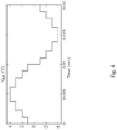
Fig. 4 shows an example output from a system comprising a plurality of units such as those shown inFig. 1 coupled in series; -
Fig. 5 shows a schematic of another example unit for installation in a complex product; -
Fig. 6 shows a schematic of another example unit for installation in a complex product; -
Fig. 7 shows an example apparatus for charging a plurality of batteries; -
Fig. 8 shows an example complex product comprising a plurality of units, such as those shown inFigs. 1 ,5 and6 , arranged to provide a string cell inverter; and -
Fig. 9 shows a cooling circuit for routing cooling around a plurality of units such as those shown inFig. 6 . - The present disclosure has a number of interrelated applications. Some of these are summarised below.
-
Fig. 1 illustrates some embodiments of the present disclosure which provide aunit 100 for installation in a complex product. Each unit may comprise DC energy storage, such as a battery of energy storage cells which may be managed by a battery management system. These units may also comprise an inverter for providing an AC output from the unit. The output of a plurality of theseunits 100 may be coupled together, for example in series, for example to act as a string cell inverter to provide AC energy. Each of the units may be interchangeable in the sense that any one of theunits 100 may be replaced by another similar such unit. Each such unit may be provided in a separate housing to aid its installation into a complex product. The complex product may comprise a plurality of separate compartments, which may be of different and/or irregular shapes. The units, 100 may be installed into these separate compartments and connected together. Although the total space occupied by the battery and inverter as a whole may increase, such embodiments may permit the complex product as a whole to be reduced in size by the more efficient use of space. - The complex product may also comprise a compartment for an electric machine, and the electric machine may require an AC power supply. The electric machine may comprise a multi-phase AC electric motor, such as a traction motor, and may be provided as a part of the product. It will be appreciated in the context of the present disclosure that a "complex product" may be any apparatus which comprises components assembled together. Those components may be made and sold separately, for example as spare parts, or as components to be assembled together to provide the full working product. In some complex products, some components may not be visible during normal use. For example: electric and hybrid vehicles, generators, industrial scale energy storage units, engines, vacuum cleaners, hand dryers, drones, robots and autonomous vehicles all provide examples of complex products, but of course there are others too.
- The present disclosure also provides a
control logic control logic - In some embodiments illustrated by
Fig. 1 , eachunit 100 comprises a housing carrying an AC output. A battery, a battery management system and an inverter are provided in the housing. The inverter comprises a plurality of voltage controlled impedances, VCls, for providing a power supply to the AC output based on energy from the battery. In some embodiments the housing carries a timing signal input configured to receive a timing signal from outside the housing. In such embodiments the timing signal input is coupled to control the impedances of the VCls so that changes in the impedances of the VCls are synchronised with the timing signal. - As illustrated in
Fig. 5 , in some embodiments of the disclosure, the battery management system also comprises at least oneVCI 25. The housing carries a DC input for coupling to a DC power supply outside the housing. A controller is provided in the housing and is configured to operate at least one VCI of the inverter and the at least one VCI of the battery management system using the DC power supply. -
Fig. 1 andFig. 2 illustrate embodiments of the present disclosure which may include control logic for controlling a string cell inverter. The string cell inverter may comprise a plurality of interchangeable units such as those described above, which may be arranged in series to provide the functionality of a string cell inverter. In some embodiments, the control logic is configured to receive signals comprising information based on at least one of battery data and demand for power, and control the AC output of each respective interchangeable unit of the string cell inverter based on the at least one of battery data and demand for power. In some embodiments the string cell inverter is coupled to a multi-phase AC electric motor, and the control logic is configured to send signals to each of the interchangeable units based on the desired torque of the multi-phase AC electric motor to control the output of AC power from each of the interchangeable units. - Some embodiments of the disclosure provide an
apparatus 500 comprising aconnection 505 for coupling a plurality of sets ofmulti-phase windings 300 to a multi-phaseAC power coupling 510, such as shown inFig. 7 . The multi-phase AC power coupling may be a multi-phase AC power supply, for example a power network such as the National Grid. Themulti-phase windings 300 may be induction windings. Themulti-phase windings 300 may be provided by the electric machine described above and in more detail below, such as an electric motor. Theconnection 505 is arranged so that each set of multi-phase windings is couplable to a respective corresponding phase of theAC power coupling 510. Each phase of each set 300 is couplable to a respectivecorresponding inverter 9, and eachinverter 9 is couplable to a respectivecorresponding battery 3 so that at least one separate battery-inverter pair is couplable by theconnection 505 to the respective corresponding phase of theAC power coupling 510 via the corresponding phase of itsset 300. Such embodiments of the disclosure may allow effective charging ofbatteries 3 from an AC power source by using the sets ofmulti-phase windings 300 as low-pass filters. Each battery-inverter pair may be provided by one of theinterchangeable units 100 described above and in more detail below. - Some embodiments of the disclosure provide an
electric vehicle 700, as shown inFig. 8 . Theelectric vehicle 700 comprises a plurality ofbatteries 3 each comprising at least one energy storage cell, a multi-phase ACelectric motor 300, and a plurality of string cell inverters. Each respective string cell inverter comprises a plurality ofinverter units 100 arranged to be coupled to control the output of the plurality ofbatteries 3 to a respective phase of the ACelectric motor 300. - Some embodiments of the disclosure provide a method of installing an inverter into a complex product comprising an electric machine requiring an AC power supply, and wherein the complex product comprises a plurality of separate compartments. The complex product may be the electric vehicle, as shown in
Fig. 8 . The electric machine may be the electric machine described above and in more detail below, such as an electric motor. The method comprises distributing a plurality ofinverter units 100 around the plurality of separate compartments of the complex product, and coupling the plurality of inverter units together for providing power to the electric machine. - Some embodiments of the disclosure provide a plurality of interchangeable units arranged to provide a string cell inverter for powering an electric machine. The interchangeable units may be the units described above and described in more detail below. The electric machine may be the electric machine described above and in more detail below, such as an electric motor. Each interchangeable unit comprises a housing carrying an AC output, a battery comprising at least one battery cell, a battery management system configured to control charge supplied to and/or from the at least one battery cell of a battery, and a respective inverter. Each interchangeable unit is configured to be coupled in series via its AC output so as to provide a string cell inverter for supplying AC power from the battery. The apparatus comprises a cooling circuit configured to route coolant via each of the plurality of interchangeable units.
- Some embodiments of the disclosure also provide a method of installing an inverter into a complex product comprising an electric machine requiring an AC power supply. The complex product may be the
electric vehicle 700 shown inFig. 8 . The electric machine may be the electric machine described above and in more detail below, such as an electric motor. Each inverter comprises a housing carrying an AC output, an inverter for supplying AC power via the AC output. The housing carries a coolant inlet port and a coolant outlet port. The method comprises coupling the AC output of each inverter together to the electric machine, and coupling the coolant inlet port and the coolant outlet port of each inverter together to provide a cooling circuit to route coolant via each of the plurality of inverters. - Examples of the present disclosure allow AC power to be delivered to and/or from a plurality of batteries in a more efficient and controlled way. Because each of the units comprises a battery, a battery management system and an inverter in a common housing, each of the units may be interchangeable and easily swapped in or out. Furthermore, because a plurality of units may be coupled together, the power rating of the components of each unit, and in particular the power rating of the inverter and the VCls of each unit, may be lower thus allowing cheaper components to be used. The units can also be distributed among compartments of the complex product around the complex product to make more efficient use of space and distribute weight more evenly.
- To put these embodiments into context, the following disclosure introduces example apparatus in which they may be used. These apparatus happens to employ example configurations, and these are advantageous, but other configurations may also be used.
-
Fig. 1 shows anexample unit 100 for installation in a complex product comprising an electric machine requiring an AC power supply. In the example shown inFig. 1 , theunit 100 comprises ahousing 1 carrying anAC output 11. In some examples thehousing 1 is a closed container which may be sealed, and may comprise ports for various connections (as described in more detail below) to the components inside thehousing 1. Thehousing 1 may be regularly shaped or irregular in shape. Inside thehousing 1 is abattery 3 comprising five battery cells and acontroller 5, although in other examples (such as shown inFig. 6 ) acontroller 5 is not required. Thecontroller 5 may be provided by control logic. Thecontroller 5 is coupled to a battery management system 7 and aninverter 9. - The
inverter 9 comprises four voltage controlled impedances, VCls, 13 arranged in an H-bridge. The VCls each comprise two main connections and a control connection. A voltage applied to the control connection can control the impedance of a conduction path between the two main connections. The H-bridge may be provided as part of an integrated circuit. - In the example shown in
Fig. 1 , the H-bridge comprises foursuch VCIs 13 arranged to provide two inverter legs - each leg of the H-bridge comprises two VCls. In each leg, a first main connection of each VCI is coupled to a different one of two DC energy supply rails, and the second main connection of each VCI is coupled to the other VCI of that leg and to the AC output of the inverter. TheAC output 11 is thus provided between the legs of the H-bridge between the VCls 13 - theAC output 11 may comprise one terminal coupled to one leg of the H-bridge, and another terminal coupled to the other leg of the H-bridge. - In the example shown in
Fig. 1 , thehousing 1 also carries atiming signal input 15 coupled to thecontroller 5. Thetiming signal input 15 is couplable to aremote device 19, such as thecontroller 5 of anothersimilar unit 100. In the example shown inFig. 1 , thehousing 1 also carries aDC input 17 for coupling to a DC power supply from outside thehousing 1, although in other examples (such as shown inFig. 6 described in more detail below) theDC input 17 is not required. - The battery cells of the
battery 3 are coupled to the battery management system 7. The battery management system 7 may comprise VCls arranged to allow electrical power from the battery cells to be dissipated to balance the cells (not shown inFigure 1 , but givenreference number 25 inFigure 5 ). In the example shown, theinverter 9 and battery management system 7 are integrated onto a single printed circuit board and share the same single integrated microcontroller, although in other examples theinverter 9 and battery management system 7 may be provided by two separate microcontrollers and/or may be provided on separate printed circuit boards. In some examples theVCls 13 of theinverter 9 may be provided on a separate printed circuit board to the battery management system 7 to aid in heat dissipation from theVCls 13. - The
housing 1 is configured to encapsulate theunit 100 for installation into the complex product. For example, thehousing 1 is configured to protect theinverter 9,battery 3 and battery management system 7 from water ingress. - The
unit 100 is configured so that a plurality ofunits 100 can be coupled together to provide the AC power supply for the electric machine. For example, theAC output 11 may comprise two terminals. The first terminal of theAC output 11 of afirst unit 100 may be configured to couple to asecond unit 100, and the second terminal to and athird unit 100. Additionally or alternatively, the first terminal of theAC output 11 of afirst unit 100 may be configured to couple to an electric machine and the second terminal to asecond unit 100. - The battery management system 7 is configured to balance a state of charge of each of the cells of the
battery 3. For example, the battery management system is configured to control charge supplied to and/or from the battery cells of thebattery 3. For example, the battery management system 7 may be configured to control the current to a cell of thebattery 3 based on the voltage of that cell. For example, if the voltage of a cell reaches a selected threshold, the current supplied to that cell may be restricted to limit the charge supplied to that cell. This may be done by modulating the impedance of aVCI 25 coupled in parallel with the cell which is to be controlled. For example, if theVCI 25 impedance is dropped, current may discharge from the cell through theVCI 25. Additionally or alternatively, the battery management system 7 may be configured to move charge from one cell of abattery 3 to another cell of thesame battery 3, and/or to cells ofbatteries 3 ofother units 100. In some examples the determination of whether to move charge from thebattery 3 of oneunit 100 to thebattery 3 of another unit may be made bycontrol logic 19. - The
inverter 9 is configured to provide a power supply to theAC output 11 based on energy from thebattery 3 by controlling theVCls 13. As described above, theVCIs 13 forming the H-bridge are operable to control the flow of current through them, for example they may act as switches. Accordingly, theVCls 13 may be switched between a conducting and non-conducting state by the application of a control voltage as described below. - By adjusting the impedance of the
VCls 13 the output of the H-bridge (and hence the AC output 11) can be switched from one direction (polarity) to the opposite direction. In addition, by appropriate control of theVCls 13 it can be seen fromFig. 1 that the AC output voltage can also be set to zero. - The
timing signal input 15 is configured to receive a timing signal from theremote device 19 outside thehousing 1. Thetiming signal input 15 is coupled to control the impedances of theVCIs 13 of theinverter 9 so that changes in the impedances of theVCls 13 can be synchronised with the timing signal, for example so that the impedances of theVCls 13 change in phase with the timing signal. This coupling may be direct, or it may be mediated by thecontroller 5. - Adjusting the impedance of a
VCI 13 may comprise adjusting the control voltage of theVCls 13. The control voltage may be obtained from a DC power supply, for example viaDC input 17, and operated by thecontroller 5 to control theVCls 13. This may enable theVCIs 13 to be operated in synchrony with a timing signal received via the timing signal input. For example the control voltage applied to the VCls may be synchronised to the timing signal - for example, the timing signal may comprise a series of pulses, and thecontroller 5 may apply a series of corresponding pulses of the control voltage to theVCls 13. These control pulses may be synchronised to the timing signal - e.g. each control pulse may be triggered by a rising or falling edge of that timing signal. - The
timing signal input 15 may also be operable to act as a communications interface, for example to send information such as battery data to theremote device 19. - In the example shown in
Fig. 1 thecontroller 5 is configured to control at least one of the plurality ofVCls 13 of theinverter 9 based on the timing signal received via thetiming signal input 15, although in other embodiments (such as shown inFig. 6 ) thecontroller 5 and/or theDC input 17 is not essential and theunit 100 may operate without acontroller 5 or aDC input 17 and with thetiming signal input 15 coupled to provide a control voltage which itself controls the impedances of theinverter VCIs 13. - In the example shown in
Fig.1 , thecontroller 5 is configured to operate theVCIs 13 of theinverter 9 based on the timing signal using the DC power supply received via theDC input 17. In the example shown inFig. 1 , the battery management system 7 is configured to control the at least one VCI of the battery management system 7 using the DC power supply, for example the battery management system 7 is configured to balance charge between the plurality of battery cells of thebattery 3 by operating the at least one VCI of the battery management system 7 using the DC power supply. For example, the at least one VCI of the battery management system 7 may be operated to divert charge, such as current, away from a cell, for example to a resistor or to another cell or anotherbattery 3. - In the example shown in
Fig. 1 , thecontroller 5 is configured to send signals to aremote device 19 based on at least one of: a temperature of the battery management system 7; a temperature of thebattery 3; the temperature of theinverter 9; a current supplied to and/or from thebattery 3; and a voltage of thebattery 3. - In the example shown, the timing signal is sent from the
remote device 19 that receives the signals sent by thecontroller 5. Theremote device 19 may, for example, be acontrol logic 19, as described in more detail below. -
Fig. 2 shows one way to couple a set ofunits 100 such as those shown inFig. 1 . Eachunit 100 is configured to couple to anotherunit 100 to provide a string cell inverter, as shown inFig. 2 . Each of theunits 100 may be interchangeable in the sense that any one of theunits 100 may be replaced by another - eachunit 100 provides similar, for example the same, functionality. In some examples, eachunit 100 may be identical. TheAC output 11 of eachunit 100 is configured to be couplable to at least one of anotherunit 100 and anelectric machine 300, for example as shown inFig. 2 and as described above. - In the example shown in
Fig. 2 , theelectric machine 300 comprises a multi-phase ACelectric motor 300. In the example shown, fourunits 100 are coupled together in series via their AC outputs 11 to form a string ofunits 100, although of course more orless units 100 may be coupled in this way. The string ofunits 100 may act to provide a string cell inverter (also known as a chain cell inverter). For example, a plurality ofunits 100 may be coupled in series and/or in parallel. Coupling theunits 100 in parallel may increase the current output of the string ofunits 100. - in the example shown in
Fig. 2 , a separate string of units 100 (for example a set of series coupled units 100) is coupled to each phase of the multi-phaseelectric motor 300. Because theelectric motor 300 shown inFig. 2 is a three phase motor, three strings are provided, one for each phase of theelectric motor 300. At the back of the string, an output of thelast unit 100 of each string is coupled to theAC output 11 of oneunit 100 of each of the other strings, so that each string is coupled to a reference voltage. - A single
remote device 19, such as acontrol logic 19, is configured to communicate with each of theunits 100, for example via thetiming signal input 15, to receive signals comprising information based on at least one of battery data of eachinterchangeable unit 100, and demand for power of a string cell inverter. Thecontrol logic 19 is configured to process the received signals and may be configured to store data based on the received signals in a memory. - Additionally or alternatively, the
control logic 19 may be configured to receive a demand for power from elsewhere, for example the demand for power may be controlled by a user operating the complex product. In some examples the demand for power may be proportional to a depression of a trigger or pedal, such as a gas pedal in a vehicle. In some examples the demand for power may be a demand for torque, for example a demand for torque of an electric motor. - In the example shown in
Fig. 2 , thecontrol logic 19 is configured to send a timing signal to control operation of each respectiveinterchangeable unit 100. Thecontrol logic 19 is configured to determine the phase timing of theAC output 11 of each respectiveinterchangeable unit 100 to meet the demand for power. - An example flowchart illustrating the steps of operating a
unit 100 of a string shown inFig. 2 is shown inFig. 3 . In operation, thecontrol logic 19 receives 501 information based on at least one of battery data of eachinterchangeable unit 100, a desired torque, and a demand for power of a string cell inverter. Thecontrol logic 19 makes adetermination 503 based on this information to determine the phase timing of theAC output 11 of each respectiveinterchangeable unit 100. For example, thecontrol logic 19 may make adetermination 503 based on the battery data or the demand for power, or a combination of both. Additionally or alternatively, thecontrol logic 19 may make adetermination 503 based on a desired torque output of an electric motor. - The
control logic 19 sends 505 the timing signal to controloperation 509 of each respectiveinterchangeable unit 100. The timing signal received by arespective unit 100 may be unique to thatunit 100, and/or unique to that string, for example a separate timing signal may be sent for each string corresponding to a separate phase of theelectric motor 300. In some examples thecontrol logic 19 sends 505 the timing signal directly to eachinterchangeable unit 100, for example in parallel, and in other examples thecontrol logic 19 sends the timing signal to a plurality ofunits 100 in series, for example to theunits 100 of a string in series, so that all theunits 100 of the string receive the same timing signal from thecontrol logic 19. The timing signal may comprise information unique to eachunit 100, so that if the timing signal is sent to a plurality ofunits 100 in series in a string, eachindividual unit 100 may still be operated independently of theother units 100 in that string. - The timing signal is received 507 by the
timing signal input 15 of eachrespective unit 100 and causes changes in impedances of theVCls 13 of theinverter 9 to be synchronised with the timing signal. By changing the impedance of theVCls 13 of theinverter 9, the power output of thatrespective unit 100 can be adjusted. For example, by adjusting the impedance of two of theVCls 13 of the H-bridge of theinverter 9 at a time, the AC output of aunit 100 can be switched from, for example, -1V to 0V and +1V. Additionally or alternatively, pulse width modulation, PWM, may be used, to further alter the output of thatunit 100. -
Fig. 4 shows an example output of a string ofunits 100, such as that shown inFig. 2 , for powering one of the phases of theelectric motor 300.Fig. 4 shows the voltage output of a string ofunits 100 as a function of time. Each step change in the voltage output represents at least one impedance of theVCls 13 of theinverter 9 of one of theinterchangeable units 100 changing. Because there are fourindividual units 100 in a string inFig. 2 , and each unit can provide an output of + 1V, 0V and -1V, there are four steps up to +4V and four steps down to -4V from 0V. In this way, the steps up and down can be used to provide an AC output from a DC source (for example a battery), for example by approximating the characteristic sinusoidal waveform of an AC supply. The voltage output from eachunit 100 is staggered with respect to the AC output from theother units 100 of the same string so that a series of steps up and down over time is produced. Providingmore units 100 per string may allow smaller steps up and down and therefore an improved AC output that more closely follows a desired sinusoidal waveform. Pulse width modulation, PWM, may also be used to provide smaller steps up and down. - The impedance of the
VCls 13 of eachunit 100 is synchronised to the timing signal. For example, the impedance of theVCls 13 may be synchronised to change state in sync with the timing signal. The timing signal may be a repeating/cyclical signal. The impedance of theVCls 13 may be synchronised to every cycle of the timing signal, to a selected number of cycles of the timing signal, or as a function of the timing signal. The timing signal may therefore be at a frequency greater or less than that of theAC output 11 of aunit 100 and/or a string ofunits 100. For example, a timing signal may be provided for every step change in Voltage indicated inFig. 4 - in other words, a change in impedance of aVCI 13 of one of theunits 100 may be matched to the frequency of the timing signal. In other examples, a change in impedance of aVCI 13 of aunit 100 may occur as a function of the timing signal - for example, the impedance of aVCI 13 may change after a selected delay following receipt of the timing signal. - The voltage controlled impedances described herein may comprise transistors such as insulated gate bipolar transistors, IGBTs, field effect transistors, FETs, such as junction field effect transistors, JFETS, insulated gate field effect transistors, IGFETS, metal oxide semiconductor field effect transistors, MOSFETs, and any other type of transistor. The VCls may be operated as switches. Electromechanical switches such as relays may be used, for example in some low-speed high-voltage applications. In some examples the H-bridge may be provided by a relay, such as a double pole double throw relay. In some examples a double pole double throw relay may be used in combination with a VCI. IGBTs and similar type VCls may be used in the inverter whereas FETs may be used by the battery management system.
- In some examples, the timing signal may at least partially define at least one of a frequency and a phase of the power supply to the
AC output 11 of aunit 100. For example, the impedance of theVCls 13 may be synchronised to the timing signal so that the frequency of the power supply provided by the AC outputs 11 of astring cell inverter 9 is matched to the frequency of the timing signal. - As noted above, the timing signal may be unique to that
unit 100, or unique to a string ofunits 100. For example, the timing signal of one string ofunits 100 may be out of phase with the timing signal of another string ofunits 100, to provide a multi-phase AC power supply. - In some examples the timing signal may comprise a clock signal and a data signal. For example, the
control logic 19 may send a clock signal (for example a cyclic or repeating signal), and additionally send a data signal comprising information about when the impedances of theVCls 13 of aparticular unit 100 should be controlled with respect to the clock signal. For example, the same clock signal may be sent to allunits 100 with the data signal comprising information about when the impedances of theVCls 13 of eachunit 100 should change with respect to the clock signal. In some examples thecontrol logic 19 may send the timing signal and clock signal as separate signals, and, for example, at separate times or at the same time. Splitting the timing signal into a data signal and a clock signal may reduce the bandwidth of the timing signal. - The
control logic 19 may be configured to stagger the output of each of therespective units 100 of a string with respect to each other. In some examples aseparate control logic 19 is provided for each string ofunits 100. In some examples, thecontrol logic 19 is configured to control theAC output 11 of each respectiveinterchangeable unit 100 of a string cell inverter based on the at least one of battery data and demand for power, or a combination of both. In other examples, thecontrol logic 19 is configured to send signals to each of theinterchangeable units 100 based on the desired torque of the multi-phase ACelectric motor 300 to control the output of AC power from each of theinterchangeable units 100. - The battery data may comprise at least one of: an energy state of the
battery 3; a state of charge of thebattery 3; a voltage of thebattery 3; a current output of thebattery 3; the capacity of thebattery 3; a temperature of thebattery 3. The demand for power may be determined based on a desired torque of the ACelectric motor 300. The battery data may be stored in thecontrol logic 19, for example in a memory of thecontrol logic 19. The battery data may be periodically updated, for example the battery data may be updated when a change in the battery data reaches or passes a selected threshold. - In some examples, the
control logic 19 is configured to control theAC output 11 of a first one of theinterchangeable units 100 based on the battery data of a second one of theinterchangeable units 100. For example, thecontrol logic 19 may be configured to increase or decrease the AC output of oneinterchangeable unit 100 based on the battery data of anotherinterchangeable unit 100 so as to meet the demand for power. In some examples, thecontrol logic 19 is configured to balance the energy stored acrossinterchangeable units 100, for example acrossinterchangeable units 100 of the same string. - In some examples, the
control logic 19 may be configured so that the determination made atdetermination step 503 ofFig. 3 comprises determining the demand placed on thepower output 11 of each respectiveinterchangeable unit 100 so that the sum of the AC power outputs 11 of theinterchangeable units 100 meets the demand for power. In some examples, thecontrol logic 19 is configured to determine the demand placed on thepower output 11 of aninterchangeable unit 100 based on that interchangeable unit's battery state of charge. For example, thecontrol logic 19 may make a determination that a unit's battery state of charge is low. Thecontrol logic 19 may therefore adjust the timing signal sent to each of therespective units 100 of a string so that the power demand placed on thatparticular unit 100 is reduced, and the power demand on aunit 100 with a greater battery state of charge may be increased to match the power demand for that string. - In some examples, the
control logic 19 may be configured to determine the demand placed on thepower output 11 of each respectiveinterchangeable unit 100 based on other battery data, such as an energy state of thebattery 3, a state of charge of thebattery 3, a voltage of thebattery 3, a current output of thebattery 3, the capacity of thebattery 3, and a temperature of thebattery 3. Thecontrol logic 19 may use the battery data in combination with the demand for power, for example from a string as a whole, or from a plurality of strings, to determine the demand placed on thepower output 11 of each respectiveinterchangeable unit 100. For example, if the temperature of abattery 3 of a selectedunit 100 is indicated to be high or low, for example outside a selected range, then thecontrol logic 19 may be configured to place a lower power demand on thatunit 100 to avoid damaging the battery, or to place a lower power demand on a string containing thatunit 100. A similar consideration may be made if the temperature of theinverter 9 or battery management system 7 is too high or too low. - The
control logic 19 may further be configured to not draw any power at all from a unit where the temperature is outside a second selected range. If alower power demand 100 is placed on aparticular unit 100, thecontrol logic 19 may be configured to meet the power demand by demanding more power from anotherunit 100. Additionally or alternatively, if alower power demand 100 is placed on aparticular unit 100, thecontrol logic 19 may be configured to provide a lower total power output, for example the power output from a string may be reduced. Limiting the total power output in this way may prevent damage to any of theunits 100. - With reference to the drawings in general, it will be appreciated that schematic functional block diagrams are used to indicate functionality of systems and apparatus described herein. It will be appreciated however that the functionality need not be divided in this way, and should not be taken to imply any particular structure of hardware other than that described and claimed below. The function of one or more of the elements shown in the drawings may be further subdivided, and/or distributed throughout apparatus of the disclosure. In some embodiments the function of one or more elements shown in the drawings may be integrated into a single functional unit. For example the function of the battery management system 7, the
controller 5 and theinverter 9 comprising theVCls 13, may be integrated into a single functional unit, such as a single integrated microcontroller. - In some examples, such as shown in
Fig. 5 , thehousing 1 does not comprise atiming signal input 15. In such examples thecontroller 5 may control the timing of changes in impedance of theVCls 13 of theinverter 9. For example, thecontroller 5 may be pre-programmed with a timing sequence for controlling the impedances of theVCls 13 of theinverter 9. If theunits 100 ofFig. 5 are coupled to provide a string cell inverter, then eachunit 100 of that string may be pre-programmed with a different timing sequence. - In some examples, for example as shown in
Fig. 6 , thehousing 1 carries acoolant inlet port 21 and acoolant outlet port 23. Thecoolant inlet port 21 and thecoolant outlet port 23 may be coupled via a cooling circuit in thehousing 1 configured to route coolant into thehousing 1, via at least one of theinverter 9 and thebattery 3, and out of thehousing 1. A plurality ofunits 100 may be coupled together so that thecoolant ports unit 100 are coupled to thecoolant ports other units 100 to provide a cooling circuit around the plurality ofunits 100. For example, theunits 100 providing a string of a string cell inverter may be coupled together to provide a cooling circuit for that string. - In some examples, the
control logic 19 may be thecontroller 5 of anotherinterchangeable unit 100. This avoids the need for providing a separate unit for thecontrol logic 19. - In some examples, the battery cells of the
battery 3 may be replaced with other forms of energy storage cells or other DC energy storage, for example fuel cells such as Hydrogen fuel cells. Thebattery 3 may comprise a plurality of battery cells, such as five battery cells as shown inFigs. 1 ,5 and6 , or more or less battery cells, for example only one battery cell. - In some examples, each of the
units 100 of a string ofunits 100 may be configured to operate in a positive or negative mode. For example, a family ofunits 100 may be configured to operate in a positive or negative mode. For example, a family ofunits 100 may be configured to provide a positive output, such as + 1V, and a family ofunits 100 may be configured to provide a negative output, such as -1V. In this way, each family produces half of a wave cycle of an AC output. - The three phase system shown in
Fig. 2 can be expanded to make a nine phase system. - Each
unit 100 of the nine phase system may use a single set of electronics comprising theinverter 9, thebattery management system 5 andbattery 3. Each of theunits 100 of a string can be made to fit in a compact space so that they can distributed around a complex product such as a car more easily. For example, thehousing 1 of theunits 100 may be adapted to fit in different compartments of the complex product, for example thehousing 1 may be configured to have an irregular shape. - Embodiments of the disclosure may also provide safety features such as redundancy for a system. For example, if all of the
units 100 of a string are switched to short circuit their AC outputs 11, the highest voltage in a string would only by the voltage of abattery 3 of aunit 100. If abattery 3 fails then there is redundancy as the string ofunits 100 can continue to operate with N-1units 100 working. If abattery 3 fails open circuit, the design of the H-bridge means thatVCls 13 of theinverter 9 are set to give zero output voltage and the string continues to operate with N-1units 100 working. - Providing a string cell inverter using a plurality of
units 100 described above may also offer additional advantages. For example, a typical voltage of theAC output 11 of one of theunits 100 is 60V (this may be obtained by coupling a plurality of battery cells of lower voltage together in series - for example the voltage of a battery cell may be 3.6V, 3.9V or 4V, and 12 or 14 battery cells, for example, may be coupled in series). If aunit 100 in a string ofsuch units 100 that are coupled in series fails, the maximum output of that string is only the voltage of one of the units, for example 60V. This compares to 300 to 600V in a standard inverter system commonly used in electric vehicles. Furthermore, because theVCls 13 of eachinverter 9 switch at a lower voltage than conventional inverters used in similar applications, the switching efficiency is improved due to lower voltage harmonics. Lossy emissions, for example from theVCls 13, are also reduced due to the lower switching voltage. - Use of a plurality of
units 100 coupled in series to provide a string also allows theVCls 13 of theinverter 9 of eachunit 100 to switch at a fundamental output frequency which is much lower than a typical pulse width modulation frequency conventionally used for inverters in similar applications. The pulse width modulation frequency may correspond to, or be a function of, the frequency of the timing signal. Reducing the frequency at which switching of theVCIs 13 occurs at reduces power losses from theVCIs 13. - Other embodiments of the disclosure provide a complex product comprising an electric machine requiring an AC power supply. The complex product comprises a plurality of
units 100 such as those described above in relation toFigs. 1 ,5 and6 , wherein each of theunits 100 are interchangeable with one another. The plurality ofinterchangeable units 100 may be distributed amongst different compartments of the complex product. The complex product may be an electric vehicle. - Some embodiments of the disclosure relate to a method for the provision of AC power, for example performed by the
control logic 19 discussed above. Theinterchangeable units 100 may be theinterchangeable units 100 discussed above in relation toFigs. 1 ,5 and6 . The method comprises receiving 501 information based on at least one of: battery data of aninterchangeable unit 100; a desired torque; and a demand for power, for example of aunit 100 and/or of a string ofunits 100 arranged to provide a string cell inverter. The method further comprises determining 503 based on this information the phase timing of anAC output 11 of each respectiveinterchangeable unit 100; and sending 505 a timing signal to controloperation 509 of each respectiveinterchangeable unit 100. -
Fig. 7 shows anexample apparatus 500. The apparatus comprises aconnection 505 for coupling a plurality ofsets 300 of multi-phase windings to a multi-phaseAC power coupling 510. Each set 300 of multi-phase windings may comprise motor windings. For example, each set 300 of multi-phase windings may be anelectric machine 300, for example an electric motor such as that described above, for example a three phase electric motor. The multi-phaseAC power coupling 510 may be an AC source, such as a multi-phase AC power supply, for example a power network such as the National Grid. - The
apparatus 500 is arranged so that each set 300 of windings is coupled to a respective corresponding phase of theAC power coupling 510. Each phase of each set 300 of windings is coupled to a respectivecorresponding inverter 9, and eachinverter 9 is coupled to a respectivecorresponding battery 3 so that at least one separate battery-inverter pair is couplable by the connection to the respective corresponding phase of theAC power coupling 510 via the corresponding phase of itsset 300. The battery-inverter pair may be provided by aninterchangeable unit 100, such as theinterchangeable units 100 described above. The apparatus may further comprisecontrol logic 19, such as thecontrol logic 19 described above, coupled to each of theinverters 9. - The
inverters 9 are configured to be operated to provide DC power to eachrespective battery 3 from the multi-phaseAC power coupling 510. Theinverters 9 may be configured to balance the current supplied to each phase of eachset 300. For example, theinverters 9 may be configured to balance the current supplied to each phase of each set 300 by selecting the currents supplied to each phase of each set 300 so that the sum torque on the motor windings of aset 300 is zero. - The
inverters 9 may be configured to select the current supplied to each phase of aset 300 based on battery data. The battery data may comprise at least one of a temperature of a battery management system 7, a temperature of abattery 3, a temperature of theinverter 9, a current supplied to and/or from abattery 3, and energy level of abattery 3, a state of charge of abattery 3, and a voltage of abattery 3. For example, theinverters 9 may be configured to select the current supplied to each phase of aset 300 based on an energy storage state of the mostdepleted battery 3 coupled to theset 300. - If the apparatus comprises
control logic 19, thecontrol logic 19 may be configured to determine a characteristic of eachbattery 3, the characteristic comprising at least one of a temperature of thebattery 3, a state of charge of thebattery 3 and a voltage of thebattery 3. Thecontrol logic 19 may be configured to determine a desired recharge current for eachbattery 3 based on the determined characteristic. - The apparatus described above in relation to
Fig. 7 may be used in a method to transfer energy between theAC power coupling 510 and a plurality ofbatteries 3. The method comprises providing aconnection 505 for coupling a plurality of sets ofmulti-phase windings 300 to a multi-phaseAC power coupling 510. The method may comprise operating theinverters 9 to provide DC power to eachrespective battery 3. Additionally or alternatively, the method may comprise operating theinverters 9 to deliver AC power to theAC power coupling 510, for example from thebatteries 3. This may be desirable, for example, to sell power back to a grid as part of a "feed-in" tariff, for example. The operation of theinverters 9 may be performed bycontrol logic 19. - In some examples, operating the
inverters 9 comprises operating theinverters 9 to balance the current supplied to each phase of eachset 300. In examples where the windings comprise motor windings, operating theinverters 9 to balance the current supplied to each phase of each set 300 comprises selecting the currents so that the sum torque on the motor windings of aset 300 is zero, for example so that the motor is stationary during charging of thebatteries 3. - In some examples the
inverters 9 coupled to a particular set are coupled between a reference voltage and each corresponding phase, for example as shown inFig. 2 and as described above. The reference voltage may be an earth. Balancing the current may comprise balancing the voltages across theinverters 9 coupled to theparticular set 300. - In some examples, operating the
inverters 9 to provide DC power to each respective battery comprises determining a characteristic of eachbattery 3, the characteristic comprising at least one of a temperature of thebattery 3, a state of charge of thebattery 3 and a voltage of thebattery 3. Operating theinverters 9 may comprise determining the desired recharge current for eachbattery 3 based on the determined characteristic. In some examples where the multi-phase windings are motor windings, balancing the current supplied to each phase of each set 300 of multi-phase windings comprises balancing the current so that the sum torque on each multi-phase AC electric motor is zero. -
Fig. 7 shows an exampleelectric vehicle 700. Theelectric vehicle 700 may comprise a plurality ofunits 100 arranged to provide a string cell inverter, for example such as described above in relation toFig. 2 . - The
electric vehicle 700 shown inFig. 7 comprises a plurality ofbatteries 3 each comprising at least one energy storage cell, a multi-phase ACelectric motor 300, and a plurality of string cell inverters. Each string cell inverter comprises a plurality ofunits 100, for example such as theunits 100 described above, arranged in series. For example, eachunit 100 may comprisehousing 1 carrying atiming signal input 11. Inside thehousing 1 there may be abattery 3, a battery management system 7, acontroller 5 and aninverter 9 comprisingVCls 13. A battery management system 7 comprising at least oneVCI 25 may also be housed inside thehousing 1 of eachunit 100. - Each string of
units 100 is coupled to a respective phase of the multi-phaseelectric motor 300. Theelectric motor 300 is coupled to adrivetrain 707 coupled to thewheels 703 of the electric vehicle. - In some examples, the
electric vehicle 700 comprises a plurality of separate compartments distributed around theelectric vehicle 700. Theunits 100 of each string may be housed in the plurality of separate compartments, for example oneunit 100 may be housed per compartment, or a plurality ofunits 100 may be housed in a single compartment. The shape of thehousing 1 of eachunit 100 may be adapted to fit in the compartments of theelectric vehicle 700. In some examples, theunits 100 are interchangeable. In some examplesrespective batteries 3 are held inseparate units 100. Theunits 100 may be coupled to controllogic 19, such as thecontrol logic 19 described above. Thecontrol logic 19 may be configured to control operation of each of theunits 100 in a manner similar to that described above in relation toFigs. 2 and3 . For example, thecontrol logic 19 may be configured to control operation ofVCls 13 of theinverter 9 using a timing signal. - Each respective string is arranged to be coupled to control the output of the plurality of
batteries 3 to a respective phase of the ACelectric motor 300. In the example shown inFig. 8 , each respective string ofunits 100 is configured to control a respective phase of the AC electric motor. - In embodiments where a battery management system 7 is present, the battery management system may be configured to control charge supplied to and/or from an energy storage cell of the
battery 3, for example using at least one batterymanagement system VCI 25 in a manner such as that described above. - To operate the
electric vehicle 700, thecontrol logic 19 may control the plurality ofunits 100 forming a string in a manner such as that described above in relation toFigs. 2 and3 . For example, thecontrol logic 19 may provide a timing signal to control operation of theVCls 13 of eachunit 100. Thecontrol logic 19 may make a determination of a demand for power from eachunit 100 based on a desired torque of theelectric motor 300, for example by operation of a switch or pedal by a user. - As described above, a plurality of
units 100 may be arranged to provide a string cell inverter. A string ofunits 100 may be arranged to provide a string cell inverter for each phase of a multi-phase electric machine such as an electric motor. The string cell inverter may be referred to as an inverter. The inverter may be installed into a complex product such as the electric vehicle described above in relation toFig. 8 . Theelectric vehicle 700 may comprise a plurality of separate compartments distributed around the footprint of theelectric vehicle 700. The plurality of separate compartments of the complex product may be irregular in shape. Each of theunits 100 may be identical in shape and/or function, and therefore may be interchangeable. - The method of installation may comprise distributing a plurality of
inverter units 100 around the plurality of separate compartments of thecomplex product 700. The method may further comprise coupling the plurality ofinverter units 100 together for providing power to the electric machine. - For example, the plurality of
inverter units 100 may be coupled together in at least one of series (as shown inFig. 8 ) and parallel. In some examples, a string ofunits 100 may compriseunits 100 coupled in series and in parallel, for example to increase the current output from a string. - Coupling the plurality of inverter units together may comprise coupling the
inverter units 100 together to provide a multi-phase string cell inverter for powering theelectric machine 300. -
Fig. 6 shows aninterchangeable unit 100 that may be arranged to provide a string cell inverter for powering anelectric machine 300, such as shown inFigs. 2 and8 . Theinterchangeable units 100 may comprise the features of any of theinterchangeable units 100 described above. Eachinterchangeable unit 100 comprises ahousing 1 carrying anAC output 11, abattery 3 in the housing comprising at least one battery cell, a battery management system 7 in thehousing 1, and arespective inverter 9 in thehousing 1. Thehousing 1 may also carry atiming signal input 15 coupled to controllogic 19, such as described above in relation toFig. 1 . - The
housing 1 of each respectiveinterchangeable unit 100 carries acoolant inlet port 21 and acoolant outlet port 23. Between thecoolant inlet port 21 and thecoolant outlet port 23 is a coolant circuit inside thehousing 1. The coolant circuit may route coolant via components of theunit 100 in thehousing 1, such as thebattery 3, the battery management system 7, including a batterymanagement system VCI 25 and/or theinverter 9, including theinverter VCIs 13. Thecoolant inlet port 21 and thecoolant outlet port 23 may be coupled to thecoolant inlet 21 andcoolant outlet ports 23 of otherrespective units 100 via a cooling circuit outside theunits 100, as shown inFig. 9 . For example, the cooling circuit may route coolant around different compartments of a complex product such as anelectric vehicle 700 described above and as shown inFig. 8 . - The cooling circuit may route coolant via a plurality of
units 100 in series and/or in parallel. In the example shown inFig. 9 , the coolant circuit routes coolant via fourunits 100 in series. Thecoolant outlet port 23 of oneunit 100 feeds thecoolant inlet port 21 of anotherunit 100. In the example shown inFig. 9 there are two cooling circuits, one for each string ofunits 100. The coolant circuit may be coupled to a heat sink to dissipate heat, such as aradiator 600 as illustrated inFig. 9 . The heat sink may comprise a pump. The heat sink and/or the pump may be coupled to control logic 19 (not illustrated inFig. 9 ). - Each
interchangeable unit 100 is configured to be coupled in series via itsAC output 11 so as to provide a string cell inverter for supplying AC power from thebattery 3, such as described above in relation toFig. 2 . The cooling circuit is configured to route coolant via each of the plurality ofinterchangeable units 100. The cooling circuit is configured to route coolant from outside thehousing 1 of each respectiveinterchangeable unit 100, via both thebattery 3 and theinverter 9 inside thehousing 1, and back outside thehousing 1. - In use, the cooling circuit is operated, for example using a pump, to pump coolant around the plurality of
interchangeable units 100. The pump may be part of the heat sink, such as theradiator 600 illustrated inFig. 9 . Operation of the pump may be controlled by thecontrol logic 19. The rate of flow of coolant may be based on at least one of battery data, a demand for power and a demand for torque, for example the rate of flow of coolant may be based on the power demand placed on aunit 100, or on a plurality ofunits 100 such as a string ofunits 100. For example, thecontrol logic 19 may make a determination of the flow rate based on at least one of battery data, a demand for power and a demand for torque. For example, thecontrol logic 19 may determine that the rate of flow of coolant increases in proportion to the power demand of a string ofunits 100 shown inFig. 2 . - In operation, as illustrated in
Fig. 9 , the cooling circuit routes coolant from oneunit 100 to the next 100, and routes the coolant from outside thehousing 1, around components of theunit 100 such as thebattery 3, aVCI 25 of the battery management system 7 and theinverter 9VCls 13, and back out of thehousing 1. The cooling circuit may then route that coolant in series to anotherunit 100, or back to a coolant reservoir and/or a radiator such as theradiator 600 shown inFig. 9 to dissipate heat transferred to the coolant. - As described above in relation to
Fig. 7 , theapparatus 500 shown inFig. 7 may be used to charge a plurality ofbatteries 3. Also described herein is another method for charging a plurality ofbatteries 3. The method may comprise coupling each of a plurality of sets ofmulti-phase induction windings 300 to a respective phase of a multi-phaseAC power supply 510. Each phase of each set of multi-phase AC induction windings 300 is coupled to a respective phase of theAC power supply 510 and to a respective at least oneinverter 9. Each at least oneinverter 9 is coupled to a respective at least onebattery 3, for example to form a battery-inverter pair. The method comprises operating each respective at least oneinverter 9 coupled to each phase of each set ofmulti-phase induction windings 300 to provide DC power to each respective at least onebattery 3. Also described herein is an apparatus for controlling an AC electric motor. The apparatus comprises a plurality of inverters having AC outputs arranged in series to provide a string cell inverter. The string cell inverter is configured to couple to the AC electric motor. The apparatus also comprises control logic, which may act as a master controller. The control logic is configured to control each of the inverters. The control logic is configured to control operation of each inverter of the string cell inverter based on a desired torque output of the AC electric motor. Each inverter may carried in a separate housing. - The plurality of inverters may be provided by a plurality of interchangeable units, each interchangeable unit comprising a battery inside a housing comprising at least one battery cell, and a battery management system inside the housing for controlling charge supplied to and/or from the at least one battery cell of the battery. Each interchangeable unit may carry a communication interface configured to send and receive signals to the master controller. Each interchangeable unit may carry a controller in the housing configured to control the AC power supply of each inverter based on a timing signal received from the master controller via the communication interface. One of the interchangeable units may be configured to provide the functionality of the control logic acting as the master controller.
- In some examples, one or more memory elements can store data and/or program instructions used to implement the operations described herein. Embodiments of the disclosure provide tangible, non-transitory storage media comprising program instructions operable to program a processor to perform any one or more of the methods described and/or claimed herein and/or to provide data processing apparatus as described and/or claimed herein.
- The
control logic control logic
Claims (14)
- A control logic (19) for controlling AC power supplied to each phase of a multi-phase AC electric motor (300) from a plurality of interchangeable units (100);wherein each interchangeable unit (100) comprises:an AC output (11);a battery (3) comprising at least one battery cell; andan inverter (9) for supplying AC power to the AC output (11) based on energy from the battery (3), characterized in that each interchangeable unit (100) comprises a battery management system (7) configured to control charge supplied to and/or from the at least one battery cell of a battery (3); andwherein the control logic is configured to send signals to each of the interchangeable units (100) based on the desired torque of the multi-phase AC electric motor (300) to control the output of AC power from each of the interchangeable units (100).
- The control logic (19) of claim 1 wherein the control logic is configured to send balancing signals to each of the interchangeable units (100) to balance the energy stored across the plurality of interchangeable units (100).
- The control logic (19) of claim 1 or 2 wherein the control logic is configured to receive signals comprising information based on at least one of battery data of each interchangeable unit (100), and demand for power of the string cell inverter; and
wherein the control logic is configured to control the AC output (11) of each respective interchangeable unit (100) of the string cell inverter based on the at least one of battery data and demand for power. - The control logic (19) of any of the previous claims wherein the control logic is configured to control the AC output (11) of a first one of the interchangeable units (100) based on the battery data of a second one of the interchangeable units (100).
- The control logic (19) of any of the previous claims wherein the control logic is configured to increase or decrease the AC output (11) of one interchangeable unit (100) based on the battery data of another interchangeable unit so as to meet the demand for power.
- The control logic (19) of any of the previous claims wherein the control logic is configured to determine the phase timing of an AC output (11) of each respective interchangeable unit (100) to meet the demand for power.
- The control logic (19) of any of the previous claims wherein the control logic is configured to determine the demand placed on the power output of an interchangeable unit (100) based on that interchangeable unit's battery state of charge.
- The control logic (19) of any of the previous claims wherein the control logic is configured to determine the demand placed on the power output of each respective interchangeable unit (100) so that the sum of the AC power outputs of the interchangeable units (100) meets the demand for power.
- The control logic (19) of any of the previous claims wherein controlling the output of an interchangeable unit (100) comprises using pulse width modulation.
- The control logic (19) of any of the previous claims wherein the battery data comprises at least one of: a state of charge of the battery (3); a voltage of the battery (3); a current output of the battery (3); the capacity of the battery (3); a temperature of the battery (3).
- The control logic (19) of any of the previous claims wherein the string cell inverter is configured to provide power to an AC electric motor (300) and wherein the demand for power is determined based on a desired torque of the AC electric motor (300).
- The control logic (19) of any of the previous claims wherein the control logic is configured to send signals to each of the interchangeable units (100) based on battery data from at least one of the interchangeable units (100).
- The control logic (19) of any of the previous claims wherein the inverter (9) comprises a plurality of VCls (13) for providing a power supply to the AC output (11), and wherein the control logic is configured to send signals to each of the interchangeable units (100) in the form of a timing signal to control the impedances of the VCls (13) so that changes in the impedances of the VCls (13) are synchronised with the timing signal.
- Apparatus comprising components assembled together, the apparatus comprising an electric machine requiring an AC power supply comprising the control logic (19) of any of claims 1 to 13.
Applications Claiming Priority (3)
| Application Number | Priority Date | Filing Date | Title |
|---|---|---|---|
| GB1609123.3A GB2550601B (en) | 2016-05-24 | 2016-05-24 | Methods and apparatus for the provision of AC power |
| EP17727669.8A EP3465906B1 (en) | 2016-05-24 | 2017-05-23 | Methods and apparatus for the provision of ac power |
| PCT/GB2017/051443 WO2017203236A1 (en) | 2016-05-24 | 2017-05-23 | Methods and apparatus for the provision of ac power |
Related Parent Applications (2)
| Application Number | Title | Priority Date | Filing Date |
|---|---|---|---|
| EP17727669.8A Division EP3465906B1 (en) | 2016-05-24 | 2017-05-23 | Methods and apparatus for the provision of ac power |
| EP17727669.8A Division-Into EP3465906B1 (en) | 2016-05-24 | 2017-05-23 | Methods and apparatus for the provision of ac power |
Publications (2)
| Publication Number | Publication Date |
|---|---|
| EP3751726A1 EP3751726A1 (en) | 2020-12-16 |
| EP3751726B1 true EP3751726B1 (en) | 2024-01-31 |
Family
ID=56369885
Family Applications (3)
| Application Number | Title | Priority Date | Filing Date |
|---|---|---|---|
| EP20188074.7A Active EP3751726B1 (en) | 2016-05-24 | 2017-05-23 | Apparatus for the provision of ac power |
| EP20188079.6A Active EP3751727B1 (en) | 2016-05-24 | 2017-05-23 | Methods and apparatus for the provision of ac power |
| EP17727669.8A Active EP3465906B1 (en) | 2016-05-24 | 2017-05-23 | Methods and apparatus for the provision of ac power |
Family Applications After (2)
| Application Number | Title | Priority Date | Filing Date |
|---|---|---|---|
| EP20188079.6A Active EP3751727B1 (en) | 2016-05-24 | 2017-05-23 | Methods and apparatus for the provision of ac power |
| EP17727669.8A Active EP3465906B1 (en) | 2016-05-24 | 2017-05-23 | Methods and apparatus for the provision of ac power |
Country Status (4)
| Country | Link |
|---|---|
| US (1) | US10985686B2 (en) |
| EP (3) | EP3751726B1 (en) |
| GB (1) | GB2550601B (en) |
| WO (1) | WO2017203236A1 (en) |
Families Citing this family (8)
| Publication number | Priority date | Publication date | Assignee | Title |
|---|---|---|---|---|
| US11820218B2 (en) * | 2016-08-10 | 2023-11-21 | Briggs & Stratton, Llc | User-scalable power unit including removable battery packs |
| DE102018202589A1 (en) * | 2018-02-21 | 2019-08-22 | Audi Ag | Battery for an electrically driven motor vehicle and charging device for charging a battery of an electrically driven motor vehicle |
| US11084393B2 (en) * | 2018-08-21 | 2021-08-10 | Ford Global Technologies, Llc | Vehicle microgrid plug and play power outlet panel |
| KR102333914B1 (en) * | 2019-08-16 | 2021-12-13 | 최창준 | Power Line Communication with Polarity switching |
| CN111098744B (en) * | 2019-12-31 | 2021-02-02 | 上海钧正网络科技有限公司 | Site vehicle processing method, system, terminal and readable storage medium |
| CN112044799A (en) * | 2020-08-20 | 2020-12-08 | 博众精工科技股份有限公司 | Method and system for judging surface cleanliness of battery replacement station |
| TWI811759B (en) * | 2021-08-10 | 2023-08-11 | 凱納股份有限公司 | Intelligent energy module of electrically assisted bicycle |
| US11831251B2 (en) * | 2021-12-03 | 2023-11-28 | Abb Schweiz Ag | Voltage rate-of-change control for wide-bandgap-based inverter circuits for driving electric motors |
Citations (1)
| Publication number | Priority date | Publication date | Assignee | Title |
|---|---|---|---|---|
| US20150044520A1 (en) * | 2012-03-29 | 2015-02-12 | Robert Bosch Gmbh | Method for Heating Energy Storage Cells of an Energy Storage System, and Heatable Energy Storage System |
Family Cites Families (20)
| Publication number | Priority date | Publication date | Assignee | Title |
|---|---|---|---|---|
| US3701001A (en) * | 1971-10-12 | 1972-10-24 | Gen Motors Corp | Three-phase inverter control circuit |
| US3697843A (en) * | 1971-11-30 | 1972-10-10 | Gen Motors Corp | Three-phase inverter control circuit |
| US4204268A (en) * | 1978-08-02 | 1980-05-20 | United Technologies Corporation | Auxiliary commutation circuit for an inverter |
| JPH07108095B2 (en) * | 1984-01-20 | 1995-11-15 | 株式会社日立製作所 | Inverter device and control method thereof |
| US5272615A (en) * | 1992-05-01 | 1993-12-21 | Wert Harry E | Digital controlled inverter and method |
| JP2003086157A (en) * | 2001-09-11 | 2003-03-20 | Matsushita Electric Ind Co Ltd | On-vehicular type portable power unit |
| US8872474B2 (en) | 2006-02-09 | 2014-10-28 | Karl F. Scheucher | Fail safe serviceable high voltage battery pack |
| JP5469813B2 (en) * | 2008-01-29 | 2014-04-16 | 株式会社日立製作所 | Battery system for vehicles |
| KR100999263B1 (en) * | 2008-05-27 | 2010-12-07 | 기아자동차주식회사 | Case structure of integrated package module for hybrid vehicle |
| CN102105319A (en) * | 2008-06-27 | 2011-06-22 | 普罗特拉公司 | Vehicle battery systems and methods |
| DE102010026608A1 (en) * | 2010-07-09 | 2012-01-12 | Magna Steyr Fahrzeugtechnik Ag & Co. Kg | Device for attaching power supply modules to electric appliance of electric car, has alternating current (AC)-direct current (DC) converters whose AC and DC sides are coupled to device-side coils and electric appliance respectively |
| US20130181519A1 (en) * | 2010-10-01 | 2013-07-18 | Woog-Young Lee | Power conversion system for energy storage system and controlling method of the same |
| US9461488B2 (en) * | 2011-06-09 | 2016-10-04 | Henry Shum | Battery with integrated power inverter |
| KR101283892B1 (en) * | 2011-12-07 | 2013-07-08 | 기아자동차주식회사 | Dc-dc converter control system for green car and method thereof |
| JP5955714B2 (en) | 2012-09-18 | 2016-07-20 | 株式会社東芝 | Battery pack and electric vehicle |
| KR20140096600A (en) | 2013-01-28 | 2014-08-06 | 삼성에스디아이 주식회사 | Battery Pack and method for cell balancing thereof |
| DE102013208583A1 (en) * | 2013-05-08 | 2014-11-13 | Robert Bosch Gmbh | Drive battery for the n-phase operation of an electric motor and a drive system and a method for operating the drive system |
| US9878631B2 (en) * | 2014-02-25 | 2018-01-30 | Elwha Llc | System and method for predictive control of an energy storage system for a vehicle |
| CN104953675B (en) * | 2015-07-14 | 2018-05-04 | 北京友信宏科电子科技有限公司 | Energy management equipment, electric-control system and electric-control method, electric automobile |
| CN105437995B (en) * | 2015-12-07 | 2018-05-22 | 北京友信宏科电子科技有限公司 | Module intelligent measurement and recognition methods, multichannel verification method for fault-tolerant communication |
-
2016
- 2016-05-24 GB GB1609123.3A patent/GB2550601B/en active Active
-
2017
- 2017-05-23 US US16/304,194 patent/US10985686B2/en active Active
- 2017-05-23 WO PCT/GB2017/051443 patent/WO2017203236A1/en unknown
- 2017-05-23 EP EP20188074.7A patent/EP3751726B1/en active Active
- 2017-05-23 EP EP20188079.6A patent/EP3751727B1/en active Active
- 2017-05-23 EP EP17727669.8A patent/EP3465906B1/en active Active
Patent Citations (1)
| Publication number | Priority date | Publication date | Assignee | Title |
|---|---|---|---|---|
| US20150044520A1 (en) * | 2012-03-29 | 2015-02-12 | Robert Bosch Gmbh | Method for Heating Energy Storage Cells of an Energy Storage System, and Heatable Energy Storage System |
Also Published As
| Publication number | Publication date |
|---|---|
| GB2550601A (en) | 2017-11-29 |
| EP3751727B1 (en) | 2024-04-24 |
| EP3751727A1 (en) | 2020-12-16 |
| GB2550601B (en) | 2019-06-12 |
| WO2017203236A1 (en) | 2017-11-30 |
| EP3751726A1 (en) | 2020-12-16 |
| EP3465906B1 (en) | 2020-11-25 |
| US10985686B2 (en) | 2021-04-20 |
| EP3465906A1 (en) | 2019-04-10 |
| GB201609123D0 (en) | 2016-07-06 |
| US20190214932A1 (en) | 2019-07-11 |
Similar Documents
| Publication | Publication Date | Title |
|---|---|---|
| EP3751726B1 (en) | Apparatus for the provision of ac power | |
| KR101877610B1 (en) | Battery system with battery control | |
| US10784698B2 (en) | Modulation index improvement by intelligent battery | |
| JP6215200B2 (en) | Multistage fast charging system | |
| JP6346887B2 (en) | Battery charge balance | |
| CN110949154B (en) | Charging device | |
| CN103109415A (en) | Power supply system, and method for charging at least one power cell used as an energy store for an intermediate dc circuit in a power supply system | |
| US11159114B2 (en) | Electronic transmission system | |
| US9774275B2 (en) | Systems and methods for space vector pulse width modulation switching using boot-strap charging circuits | |
| US20160118922A1 (en) | Drive battery for in-phase operation of an electric motor, drive system and a method for operating the drive system | |
| JP2020005389A (en) | Power supply system | |
| WO2014118678A2 (en) | An energy system for an electric vehicle | |
| JP2015511478A (en) | Vehicle, battery, and method for controlling battery | |
| Momayyezan et al. | A load-sharing strategy for the state of charge balancing between the battery modules of integrated reconfigurable converter | |
| CN103109449A (en) | Systems for charging an energy store, and method for operating the charging systems | |
| US10985626B2 (en) | Electric machine supplied at low voltage and associated multicellular power train | |
| KR20200020363A (en) | Inverter system for vehicle | |
| De Simone et al. | Modular multilevel converters for battery electric vehicles: variable dc voltage control to optimize battery lifetime | |
| US10389352B1 (en) | Gate loop differential mode choke for parallel power device switching current balance | |
| Despesse et al. | Battery Monitoring System using switching battery cells | |
| GB2575527A (en) | Methods and apparatus for the provision of AC power | |
| Tresca et al. | A Reconfigurable Cascaded Multilevel Converter for EV Powertrain | |
| Wu et al. | A novel CHB multilevel converter for PMSM drives with energy feedback system | |
| CN114274844A (en) | Heating control method and system for power battery of motor and electric vehicle | |
| CN114590173A (en) | Battery energy processing device, control method thereof and vehicle |
Legal Events
| Date | Code | Title | Description |
|---|---|---|---|
| PUAI | Public reference made under article 153(3) epc to a published international application that has entered the european phase |
Free format text: ORIGINAL CODE: 0009012 |
|
| STAA | Information on the status of an ep patent application or granted ep patent |
Free format text: STATUS: THE APPLICATION HAS BEEN PUBLISHED |
|
| AC | Divisional application: reference to earlier application |
Ref document number: 3465906 Country of ref document: EP Kind code of ref document: P |
|
| AK | Designated contracting states |
Kind code of ref document: A1 Designated state(s): AL AT BE BG CH CY CZ DE DK EE ES FI FR GB GR HR HU IE IS IT LI LT LU LV MC MK MT NL NO PL PT RO RS SE SI SK SM TR |
|
| STAA | Information on the status of an ep patent application or granted ep patent |
Free format text: STATUS: REQUEST FOR EXAMINATION WAS MADE |
|
| 17P | Request for examination filed |
Effective date: 20210616 |
|
| RBV | Designated contracting states (corrected) |
Designated state(s): AL AT BE BG CH CY CZ DE DK EE ES FI FR GB GR HR HU IE IS IT LI LT LU LV MC MK MT NL NO PL PT RO RS SE SI SK SM TR |
|
| RAP1 | Party data changed (applicant data changed or rights of an application transferred) |
Owner name: TURNTIDE DRIVES LIMITED |
|
| STAA | Information on the status of an ep patent application or granted ep patent |
Free format text: STATUS: EXAMINATION IS IN PROGRESS |
|
| 17Q | First examination report despatched |
Effective date: 20220622 |
|
| GRAP | Despatch of communication of intention to grant a patent |
Free format text: ORIGINAL CODE: EPIDOSNIGR1 |
|
| STAA | Information on the status of an ep patent application or granted ep patent |
Free format text: STATUS: GRANT OF PATENT IS INTENDED |
|
| INTG | Intention to grant announced |
Effective date: 20230822 |
|
| GRAS | Grant fee paid |
Free format text: ORIGINAL CODE: EPIDOSNIGR3 |
|
| GRAA | (expected) grant |
Free format text: ORIGINAL CODE: 0009210 |
|
| STAA | Information on the status of an ep patent application or granted ep patent |
Free format text: STATUS: THE PATENT HAS BEEN GRANTED |
|
| AC | Divisional application: reference to earlier application |
Ref document number: 3465906 Country of ref document: EP Kind code of ref document: P |
|
| AK | Designated contracting states |
Kind code of ref document: B1 Designated state(s): AL AT BE BG CH CY CZ DE DK EE ES FI FR GB GR HR HU IE IS IT LI LT LU LV MC MK MT NL NO PL PT RO RS SE SI SK SM TR |
|
| REG | Reference to a national code |
Ref country code: GB Ref legal event code: FG4D Ref country code: CH Ref legal event code: EP |
|
| REG | Reference to a national code |
Ref country code: DE Ref legal event code: R096 Ref document number: 602017078928 Country of ref document: DE |
|
| REG | Reference to a national code |
Ref country code: IE Ref legal event code: FG4D |