EP3751722A1 - System and method for variable dc bus voltage coupled to inverters - Google Patents
System and method for variable dc bus voltage coupled to inverters Download PDFInfo
- Publication number
- EP3751722A1 EP3751722A1 EP20178881.7A EP20178881A EP3751722A1 EP 3751722 A1 EP3751722 A1 EP 3751722A1 EP 20178881 A EP20178881 A EP 20178881A EP 3751722 A1 EP3751722 A1 EP 3751722A1
- Authority
- EP
- European Patent Office
- Prior art keywords
- voltage
- variable
- bus
- inverter
- command
- Prior art date
- Legal status (The legal status is an assumption and is not a legal conclusion. Google has not performed a legal analysis and makes no representation as to the accuracy of the status listed.)
- Granted
Links
Images





Classifications
-
- H—ELECTRICITY
- H02—GENERATION; CONVERSION OR DISTRIBUTION OF ELECTRIC POWER
- H02M—APPARATUS FOR CONVERSION BETWEEN AC AND AC, BETWEEN AC AND DC, OR BETWEEN DC AND DC, AND FOR USE WITH MAINS OR SIMILAR POWER SUPPLY SYSTEMS; CONVERSION OF DC OR AC INPUT POWER INTO SURGE OUTPUT POWER; CONTROL OR REGULATION THEREOF
- H02M7/00—Conversion of AC power input into DC power output; Conversion of DC power input into AC power output
- H02M7/42—Conversion of DC power input into AC power output without possibility of reversal
- H02M7/44—Conversion of DC power input into AC power output without possibility of reversal by static converters
- H02M7/48—Conversion of DC power input into AC power output without possibility of reversal by static converters using discharge tubes with control electrode or semiconductor devices with control electrode
-
- H—ELECTRICITY
- H02—GENERATION; CONVERSION OR DISTRIBUTION OF ELECTRIC POWER
- H02P—CONTROL OR REGULATION OF ELECTRIC MOTORS, ELECTRIC GENERATORS OR DYNAMO-ELECTRIC CONVERTERS; CONTROLLING TRANSFORMERS, REACTORS OR CHOKE COILS
- H02P5/00—Arrangements specially adapted for regulating or controlling the speed or torque of two or more electric motors
- H02P5/74—Arrangements specially adapted for regulating or controlling the speed or torque of two or more electric motors controlling two or more AC dynamo-electric motors
-
- H—ELECTRICITY
- H02—GENERATION; CONVERSION OR DISTRIBUTION OF ELECTRIC POWER
- H02M—APPARATUS FOR CONVERSION BETWEEN AC AND AC, BETWEEN AC AND DC, OR BETWEEN DC AND DC, AND FOR USE WITH MAINS OR SIMILAR POWER SUPPLY SYSTEMS; CONVERSION OF DC OR AC INPUT POWER INTO SURGE OUTPUT POWER; CONTROL OR REGULATION THEREOF
- H02M7/00—Conversion of AC power input into DC power output; Conversion of DC power input into AC power output
- H02M7/42—Conversion of DC power input into AC power output without possibility of reversal
- H02M7/44—Conversion of DC power input into AC power output without possibility of reversal by static converters
- H02M7/48—Conversion of DC power input into AC power output without possibility of reversal by static converters using discharge tubes with control electrode or semiconductor devices with control electrode
- H02M7/4826—Conversion of DC power input into AC power output without possibility of reversal by static converters using discharge tubes with control electrode or semiconductor devices with control electrode operating from a resonant DC source, i.e. the DC input voltage varies periodically, e.g. resonant DC-link inverters
-
- H—ELECTRICITY
- H02—GENERATION; CONVERSION OR DISTRIBUTION OF ELECTRIC POWER
- H02M—APPARATUS FOR CONVERSION BETWEEN AC AND AC, BETWEEN AC AND DC, OR BETWEEN DC AND DC, AND FOR USE WITH MAINS OR SIMILAR POWER SUPPLY SYSTEMS; CONVERSION OF DC OR AC INPUT POWER INTO SURGE OUTPUT POWER; CONTROL OR REGULATION THEREOF
- H02M7/00—Conversion of AC power input into DC power output; Conversion of DC power input into AC power output
- H02M7/42—Conversion of DC power input into AC power output without possibility of reversal
- H02M7/44—Conversion of DC power input into AC power output without possibility of reversal by static converters
- H02M7/48—Conversion of DC power input into AC power output without possibility of reversal by static converters using discharge tubes with control electrode or semiconductor devices with control electrode
- H02M7/493—Conversion of DC power input into AC power output without possibility of reversal by static converters using discharge tubes with control electrode or semiconductor devices with control electrode the static converters being arranged for operation in parallel
-
- H—ELECTRICITY
- H02—GENERATION; CONVERSION OR DISTRIBUTION OF ELECTRIC POWER
- H02P—CONTROL OR REGULATION OF ELECTRIC MOTORS, ELECTRIC GENERATORS OR DYNAMO-ELECTRIC CONVERTERS; CONTROLLING TRANSFORMERS, REACTORS OR CHOKE COILS
- H02P21/00—Arrangements or methods for the control of electric machines by vector control, e.g. by control of field orientation
- H02P21/0003—Control strategies in general, e.g. linear type, e.g. P, PI, PID, using robust control
-
- H—ELECTRICITY
- H02—GENERATION; CONVERSION OR DISTRIBUTION OF ELECTRIC POWER
- H02P—CONTROL OR REGULATION OF ELECTRIC MOTORS, ELECTRIC GENERATORS OR DYNAMO-ELECTRIC CONVERTERS; CONTROLLING TRANSFORMERS, REACTORS OR CHOKE COILS
- H02P21/00—Arrangements or methods for the control of electric machines by vector control, e.g. by control of field orientation
- H02P21/0003—Control strategies in general, e.g. linear type, e.g. P, PI, PID, using robust control
- H02P21/0025—Control strategies in general, e.g. linear type, e.g. P, PI, PID, using robust control implementing a off line learning phase to determine and store useful data for on-line control
-
- H—ELECTRICITY
- H02—GENERATION; CONVERSION OR DISTRIBUTION OF ELECTRIC POWER
- H02P—CONTROL OR REGULATION OF ELECTRIC MOTORS, ELECTRIC GENERATORS OR DYNAMO-ELECTRIC CONVERTERS; CONTROLLING TRANSFORMERS, REACTORS OR CHOKE COILS
- H02P27/00—Arrangements or methods for the control of AC motors characterised by the kind of supply voltage
- H02P27/04—Arrangements or methods for the control of AC motors characterised by the kind of supply voltage using variable-frequency supply voltage, e.g. inverter or converter supply voltage
- H02P27/06—Arrangements or methods for the control of AC motors characterised by the kind of supply voltage using variable-frequency supply voltage, e.g. inverter or converter supply voltage using DC to AC converters or inverters
-
- H—ELECTRICITY
- H02—GENERATION; CONVERSION OR DISTRIBUTION OF ELECTRIC POWER
- H02P—CONTROL OR REGULATION OF ELECTRIC MOTORS, ELECTRIC GENERATORS OR DYNAMO-ELECTRIC CONVERTERS; CONTROLLING TRANSFORMERS, REACTORS OR CHOKE COILS
- H02P6/00—Arrangements for controlling synchronous motors or other dynamo-electric motors using electronic commutation dependent on the rotor position; Electronic commutators therefor
- H02P6/28—Arrangements for controlling current
-
- H—ELECTRICITY
- H02—GENERATION; CONVERSION OR DISTRIBUTION OF ELECTRIC POWER
- H02M—APPARATUS FOR CONVERSION BETWEEN AC AND AC, BETWEEN AC AND DC, OR BETWEEN DC AND DC, AND FOR USE WITH MAINS OR SIMILAR POWER SUPPLY SYSTEMS; CONVERSION OF DC OR AC INPUT POWER INTO SURGE OUTPUT POWER; CONTROL OR REGULATION THEREOF
- H02M1/00—Details of apparatus for conversion
- H02M1/0003—Details of control, feedback or regulation circuits
- H02M1/0006—Arrangements for supplying an adequate voltage to the control circuit of converters
-
- H—ELECTRICITY
- H02—GENERATION; CONVERSION OR DISTRIBUTION OF ELECTRIC POWER
- H02M—APPARATUS FOR CONVERSION BETWEEN AC AND AC, BETWEEN AC AND DC, OR BETWEEN DC AND DC, AND FOR USE WITH MAINS OR SIMILAR POWER SUPPLY SYSTEMS; CONVERSION OF DC OR AC INPUT POWER INTO SURGE OUTPUT POWER; CONTROL OR REGULATION THEREOF
- H02M1/00—Details of apparatus for conversion
- H02M1/0043—Converters switched with a phase shift, i.e. interleaved
-
- H—ELECTRICITY
- H02—GENERATION; CONVERSION OR DISTRIBUTION OF ELECTRIC POWER
- H02M—APPARATUS FOR CONVERSION BETWEEN AC AND AC, BETWEEN AC AND DC, OR BETWEEN DC AND DC, AND FOR USE WITH MAINS OR SIMILAR POWER SUPPLY SYSTEMS; CONVERSION OF DC OR AC INPUT POWER INTO SURGE OUTPUT POWER; CONTROL OR REGULATION THEREOF
- H02M1/00—Details of apparatus for conversion
- H02M1/0067—Converter structures employing plural converter units, other than for parallel operation of the units on a single load
- H02M1/008—Plural converter units for generating at two or more independent and non-parallel outputs, e.g. systems with plural point of load switching regulators
-
- H—ELECTRICITY
- H02—GENERATION; CONVERSION OR DISTRIBUTION OF ELECTRIC POWER
- H02M—APPARATUS FOR CONVERSION BETWEEN AC AND AC, BETWEEN AC AND DC, OR BETWEEN DC AND DC, AND FOR USE WITH MAINS OR SIMILAR POWER SUPPLY SYSTEMS; CONVERSION OF DC OR AC INPUT POWER INTO SURGE OUTPUT POWER; CONTROL OR REGULATION THEREOF
- H02M1/00—Details of apparatus for conversion
- H02M1/14—Arrangements for reducing ripples from DC input or output
- H02M1/143—Arrangements for reducing ripples from DC input or output using compensating arrangements
-
- H—ELECTRICITY
- H02—GENERATION; CONVERSION OR DISTRIBUTION OF ELECTRIC POWER
- H02P—CONTROL OR REGULATION OF ELECTRIC MOTORS, ELECTRIC GENERATORS OR DYNAMO-ELECTRIC CONVERTERS; CONTROLLING TRANSFORMERS, REACTORS OR CHOKE COILS
- H02P21/00—Arrangements or methods for the control of electric machines by vector control, e.g. by control of field orientation
- H02P21/14—Estimation or adaptation of machine parameters, e.g. flux, current or voltage
Definitions
- This disclosure relates to a system and method for variable direct current (DC) bus voltage coupled to inverters.
- DC direct current
- the DC bus voltage is fixed at a voltage level that can determine the available alternating current (AC) output of an inverter to provide an electric motor or other load. If the DC bus voltage level is designed at a higher level than required, the capacitor that is coupled to the DC bus and the switches of the inverter may experience increased thermal stress; hence, reduced longevity. Therefore, there is need for a system and method for variable DC bus voltage coupled to inverters, where the system and method is well suited for reducing thermal stress of the DC bus capacitor or the switches within one or more inverters.
- a method and system is configured to control a first inverter and a second inverter that are coupled to variable DC voltage bus.
- the inverter inputs of the first and second inverters are coupled to a variable direct current (DC) voltage bus and the inverter outputs are connected to a first variable load and a second variable load.
- a sensor e.g., voltage sensor
- a first electronic data processor is configured to determine a first torque command and/or first speed command comprising a first direct-axis current/voltage command and a first quadrature-axis current/voltage command based on the first variable load of a first electric machine.
- a second electronic data processor is configured to determine a second torque command and/or second speed command comprising a second direct-axis current/voltage command and a second quadrature-axis current/voltage command based on the second variable load of a second electric machine.
- a voltage command estimator is configured to estimate a minimum required (e.g., target) variable DC bus voltage based on the first direct-axis current/voltage command, the first quadrature-axis current/voltage command, the second direct-axis current/voltage command, and the second quadrature-axis current/voltage command for a respective time interval.
- a minimum required (e.g., target) variable DC bus voltage based on the first direct-axis current/voltage command, the first quadrature-axis current/voltage command, the second direct-axis current/voltage command, and the second quadrature-axis current/voltage command for a respective time interval.
- the voltage command estimator is configured to provide the estimated minimum required variable DC bus voltage (e.g., command estimator determines a greater of the variable DC bus voltage required by a first variable load of the first machine or the second variable load of a second machine) to a voltage regulator to adjust the observed voltage level of the variable DC voltage bus to the estimated minimum required (e.g., target) variable DC bus voltage to maintain the operation, as commanded by the voltage/current commands, of the first electric machine under the first variable load and the second electric machine under the second variable load at the time interval.
- the estimated minimum required variable DC bus voltage e.g., command estimator determines a greater of the variable DC bus voltage required by a first variable load of the first machine or the second variable load of a second machine
- FIG. 1 is a block diagram of one embodiment of a system 11 for variable direct current (DC) bus voltage coupled to inverters.
- the first electric machine 12 is coupled to a first inverter 14 that is powered by a variable DC bus (e.g., observable at DC bus terminals 30).
- a second electric machine 112 is coupled to a second inverter 114 that is powered by the variable DC bus.
- a voltage regulator 34 is coupled to the DC bus terminals 30.
- the voltage regulator 34 is configured to regulate the voltage level of the variable DC bus based on a command estimator 36 (e.g., V DC voltage command estimator).
- a method and system 11 is configured to control a first inverter 14 and a second inverter 114 that are coupled to a variable DC voltage bus or DC bus terminals 30.
- the inverter inputs of the first inverter 14 and second inverter 114 are coupled to a variable direct current (DC) voltage bus at DC bus terminals 30 and the inverter outputs are connected to a first variable load (e.g., first electric machine 12) and a second variable load (e.g., second electric machine 112).
- a sensor 32 e.g., voltage sensor
- a first electronic data processor 24 is configured to determine a first torque command and/or first speed command comprising a first direct-axis current/voltage command and a first quadrature-axis current/voltage command based on the first variable load of a first electric machine 12.
- a second electronic data processor 124 is configured to determine a second torque command and/or second speed command comprising a second direct-axis current/voltage command and a second quadrature-axis current/voltage command based on the second variable load of a second electric machine 112.
- the first inverter 14 operates to control the first electric machine 12 in one or more of the following modes: voltage control mode, a torque control mode, a sensorless position mode, a phase shift control mode, a triangular waveform control mode, a trapezoidal waveform control mode, or a space-vector-pulse-width-modulation control mode.
- the first inverter 14 operates or controls the first electric machine 12 in the voltage control mode
- the second inverter 114 operates or controls the second electric machine 112 in the torque control mode.
- a sensorless position mode means that the electric motor is not associated with an encoder, resolver or magnetic field sensor and a magnet embedded in a rotor shaft of the electric motor to estimate rotor position, rotor rotational velocity or torque of the electric motor. Instead, a machine state estimator and control module (16, 116) detects or estimates (e.g., from signal feedback from phase outputs) the rotor position, rotor velocity and/or torque of the electric machine or electric motor (12, 112).
- the electric motor or electric machine may be associated with an encoder, resolver, a magnetic field sensor and a magnet embedded in a rotor shaft of the electric motor, or another machine sensor to detect or estimate rotor position, rotor rotational velocity or torque of the electric machine, where the output of the machine sensor is coupled to a respective inverter or a machine state estimator and control module (16, 116).
- a voltage command estimator 36 is configured to estimate a minimum required variable DC bus voltage based on the first direct-axis current/voltage command, the first quadrature-axis current/voltage command, the second direct-axis current/voltage command, and the second quadrature-axis current/voltage command for a respective time interval.
- the voltage command estimator 36 is configured to provide the estimated minimum required variable DC bus voltage (e.g., command estimator determines a greater of the variable DC bus voltage required by a first variable load of the first machine or the second variable load of a second machine) to a voltage regulator 34 to adjust the observed voltage level of the variable DC voltage bus to the estimated minimum required variable DC bus voltage to maintain the operation, as commanded by the voltage/current commands, of the first electric machine 12 under the first variable load and the second electric machine 112 under the second variable load at the time interval.
- the estimated minimum required variable DC bus voltage e.g., command estimator determines a greater of the variable DC bus voltage required by a first variable load of the first machine or the second variable load of a second machine
- a first module 10 comprises a first inverter 14 coupled to a first electric machine 12, which may be controlled to operate in a primary control mode (e.g., voltage control mode) and in a power generating mode of the first electric machine 12.
- a second module 110 comprises a second inverter 114 coupled to second electric machine 112, which may be controlled to operate in a secondary control mode (e.g., torque control mode) and in a motoring mode of the second electric machine 112.
- the primary control mode may be the same as or different from the secondary control mode.
- the first inverter 14 and the second inverter 114 may operate (e.g., optionally) with offset phases of alternating current output signals to provide interleaving that reduces the ripple current and/or ripple voltage of the variable DC bus.
- the first inverter 14 and the second inverter 114 have their direct current (DC) inputs coupled to the DC bus terminals 30.
- a capacitor 28 or a DC link capacitor 28 is connected across or in parallel with respect to the terminals of the DC bus.
- a sensor 32 (e.g., voltage sensor) is coupled to the DC bus terminals 30. Further, a voltage regulator 34 is coupled to the DC bus terminals 30 and may be connected or wired in parallel with the sensor 32.
- the first module 10, first inverter 14, or first electronic data processor 24 provides one or more data messages to the voltage command estimator 36; the second module 110 provide, the second inverter 114, or the second electronic data processor 124 provides one or more data messages to the voltage command estimator 36.
- the data messages may comprise any of the following: (1) a first torque command and/or first speed command comprising a first direct-axis current/voltage command and a first quadrature-axis current/voltage command based on the first variable load of a first electric machine 12 and (2) a second torque command and/or second speed command comprising a second direct-axis current/voltage command and a second quadrature-axis current/voltage command based on the second variable load of a second electric machine 112.
- the voltage command estimator 36 may estimate a commanded estimated variable DC bus voltage based on the data messages received form the first module 10, the second module 110, or both.
- the first inverter 14 comprises first inverter 14 switches that output alternating current to the first electric machine 12 in accordance with one or more phases of alternating current outputs. As illustrated in FIG. 1 , there are three-phase connections between the first inverter 14 and the first electric machine 12.
- the first data processor 24 controls the switching states of the first inverter 14 switches in accordance with a control mode or modulation scheme via control signals that are provided via one or more data ports 18 to the control terminals (e.g., gate terminal or base terminal) of each switch, where the first inverter switches 26 are illustrated in FIG. 3 as insulated-gate bipolar junction transistors (S1 through S12, inclusive).
- the first inverter 14 comprises first electronic data processor 24, a data storage device 22 and one or more data ports 18 that can communicate with each other via a data bus 20. Further, the data ports 18 are coupled to a first machine state estimator and control module 16 and the first inverter switches 26.
- the first machine state estimator and control module 16 is arranged to receive electrical signals from the alternating current output phases of the inverter switches 26, which the first electronic data processor 24 can use to estimate rotor position, rotor velocity, and rotor torque, among other possibilities.
- the transmission lines or conductors that are coupled between the first machine state estimator and control module 16 and the phase output terminals of the first inverter switches 26 are illustrated as dashed lines to indicate that the conductors are optional. Accordingly, in an alternate embodiment, the first machine state estimator and control module 16 may obtain sensor data from a machine sensor (not shown) associated with the rotor of the first electric machine 12.
- the second inverter 114 comprises second inverter switches 126 that output alternating current to the second electric machine 112 in accordance with one or more phases. As illustrated in FIG. 1 , there are three-phase connections between the second inverter 114 and the second electric machine 112.
- the second data processor 124 controls the switching states of the second inverter switches 126 in accordance with a control mode or modulation scheme via control signals that are provided via one or more data ports 118 to the control terminals (e.g., gate terminal or base terminal) of each switch, where the second inverter switches 126 are illustrated in FIG. 3 as insulated-gate bipolar junction transistors (S1 through S12, inclusive).
- the second inverter 114 comprises second data processor 124, a data storage device 122 and one or more data ports 118 that can communicate with each other via a data bus 120. Further, the data ports 118 are coupled to a second machine state estimator and control module 116 and the second inverter switches 126.
- the second machine state estimator and control module 116 is arranged to receive electrical signals from the alternating current output phases of the inverter switches 126, which the second electronic data processor 124 can use to estimate rotor position, rotor velocity, and rotor torque, among other possibilities.
- the transmission lines or conductors that are coupled between the second machine state estimator and control module 216 and the phase output terminals of the second inverter 114 switches are illustrated as dashed lines to indicate that the conductors are optional. Accordingly, in an alternate embodiment, the second machine state estimator and control module 116 may obtain sensor data from a machine sensor (not shown) associated with the rotor of the second electric machine 112.
- FIG. 2 is a graph that shows illustrative examples of the required (e.g., target minimum estimated) variable DC bus voltage 201 versus time 202 under hypothetical transient loads.
- the vertical axis represents the required DC bus voltage 201 (e.g., in Volts)
- the horizontal axis represents the time 202 (e.g., in seconds) in response to hypothetical or modeled changes in load, or arbitrary transient load conditions for a working vehicle that incorporates the system 11 for electric motors or actuators that propel a vehicle or drive implements, associated with the work vehicle (e.g., off-road work vehicle).
- the first minimum estimated variable DC bus voltage is indicated by the dashed lines
- the second minimum estimated variable DC bus voltage is indicated by solid lines.
- the voltage command estimator 36 determines a greater or maximum of the first minimum estimated variable DC bus voltage and the second minimum estimated variable DC bus voltage to regulate the resultant target variable DC bus voltage at the DC bus terminals 30.
- the first minimum estimated variable DC bus voltage relates to the first electric machine 12 operating in a power generating mode or another operational mode; the second minimum estimated variable DC bus voltage relates to a second electric machine 112 operating in a motoring mode or another operational mode.
- a first voltage deviation 207 of the first minimum estimated variable DC bus voltage is less than a second voltage deviation 209 of the second minimum estimated variable DC bus voltage. Further, a first required voltage change per unit time or first slew rate of the of first minimum estimated variable voltage DC bus is less than a second voltage change per unit time or second slew rate of the second minimum estimated variable voltage DC bus. Accordingly, the longevity of the electric machine is potentially increased by reduced machine winding insulation stress (e.g., thermal stress that may be communicated to machine bearings and/or electric motor stress) by minimizing the required voltage change per unit time or required slew rate of estimated variable DC voltage bus at DC bus terminals 30.
- machine winding insulation stress e.g., thermal stress that may be communicated to machine bearings and/or electric motor stress
- the first minimum estimated variable voltage DC bus can be selected for a time interval in which it is the greater or maximum of the first minimum estimated variable DC bus voltage and the second minimum estimated variable DC bus voltage. Accordingly, in the above illustrative example the longevity of capacitor 28 (e.g., DC link capacitor 28) is potentially increased because of the above first required voltage change per unit time or first slew rate of the variable DC bus voltage is less than a second voltage change per unit time or second slew rate of the second minimum estimated variable DC bus voltage.
- capacitor 28 e.g., DC link capacitor 28
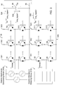
- FIG. 3 is a schematic that shows an illustrative schematic of the switches (26, 126) of the first inverter 14 and the second inverter 114 that are fed by a variable DC bus with a capacitor 28 to reduce ripple current on the variable DC bus.
- the first inverter 14 and the second inverter 114 are coupled to the DC bus terminals 30.
- the first inverter 14 has first inverter switches 26, whereas the second inverter 114 has second inverter switches 126.
- the first inverter switches 26 have three phases, a first phase 301, a second phase 302 and a third phase 303.
- the second inverter switches 126 have a first phase 301, a second phase 302, and a third phase 303.
- Each of the above phases has two switches with their switched terminals arranged in series between the variable DC bus terminals 30.
- Each phase has a low-side switch and a high-side switch.
- the first inverter switches 26 and the second inverter switches 126 have control terminals such as gates or base of the switch that control the switched terminals.
- the data ports (18, 118) are coupled via one or more conductors to control terminals.
- the first data processor 24 can control the states, relative phase, activation and deactivation of the first switches via the control terminals of the first switches.
- the second data processor 124 can control the states, relative phase, activation and deactivation of the of the second switches via the control terminals of the second switches.
- first data processor 24 and the second data processor 124 can communicate with each other (e.g., via communications line, wireless communications devices coupled to their respective data ports (18, 118) or another mechanism) to control relative phases of the first switches 26 with respect to the second switches 126 in accordance with interleaving principles to reduce unwanted ripple current and/or ripple voltage on the variable DC voltage bus.
- the first electric machine may operate in the power generating mode, whereas the second electric machine (310 or 112) may operate in the machine motoring mode.
- the first inverter 14 switches produce a direct current output with a DC current component and an alternating current ripple component 304. Some of the alternating current ripple component 308 is filtered via the capacitor 28.
- the second inverter 114 accesses the filtered direct current output 306 with some of the alternating current ripple component removed, attenuated or filtered out.
- the filtered direct current output is used to drive the second switches 126 to provide three phase alternating current output signals to drive the second electric machine 112 in the motoring mode.
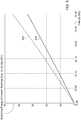
- FIG. 4 is a graph that shows the DC bus root-mean-squared (RMS) current 401 along the vertical axis and time along the horizonal axis.
- the current value of the variable DC voltage bus 407 is indicated by a solid line, whereas the current value of comparable fixed DC voltage bus 405 is indicated by dashed lines.
- FIG. 4 is a graph that shows an illustrative decrease in the DC bus root-mean-squared (RMS) current through the capacitor 28, which filters out some unwanted ripple current or alternating current signal components on the variable DC bus.
- a capacitor 28 across the variable DC bus terminals 30 has a reduced maximum current capacity rating 401 commensurate with the reduced, peak current value of the variable DC voltage bus 407 that is lower than a peak current value of the fixed constant DC bus voltage 405. Accordingly, the reduced peak current 401 tends to reduce the required size or reduced capacitance of the capacitor 28. For example, it may be possible to reduce the capacitance that is otherwise required by approximately fifteen percent to thirty-five percent. Further, the reduced peak current supports potential improved longevity of capacitor 28 (e.g., direct current link capacitor 28) in the system.
- FIG. 5 is a graph that shows the switching energy 501 versus time 502 of an inverter for a fixed DC bus versus a variable DC bus that meets the minimum estimated target required DC voltage level of the variable DC bus based on load conditions (e.g., transient load conditions on the electric machine that the inverter drives).
- the vertical axis represents the switching energy of inverter switches (e.g., in Joules) whereas the horizonal axis represents time (e.g., in seconds).
- a set of semiconductor switches (26, 126) in the first inverter 14 and the second inverter 114 have reduced time-averaged, operational switching losses 504 associated with a reduction in the variable DC bus voltage from the operational switching losses 503 associated with a fixed constant DC bus voltage.
- the operational switching losses 504 associated with the variable DC bus voltage are illustrated as the solid line, whereas the operational switching losses 503 associated with the fixed constant DC bus voltage are illustrated as the dashed line. Because of the reduction in the variable DC bus voltage, a reserved component of the DC bus voltage can be available to meet responsively and rapidly in real time transient conditions of commanded torque that demanded by load conditions on the first electric machine 12, the second electric machine 112 or both.
- FIG. 6 is a block diagram of another embodiment of a first electric machine 12 coupled to a first inverter 14 that is powered by a variable DC bus at DC terminals 30, a second electric machine 112 coupled to a second inverter 114 that is powered by the variable DC bus at DC terminals 30, and a voltage regulator 34 for regulating the voltage level of the variable DC bus based on a command estimator 136 with configurable filtering, configurable slew-rate and configurable margin (M).
- the system 111 of FIG. 6 is similar to the system 11 of FIG. 1 , except the system of FIG. 6 further comprises a low pass filter 38, a slew rate module 40 and a margin estimator 42. The operation and configuration of the low pass filter 38, slew rate module 40 and margin estimator 42 are later described in conjunction with FIG. 8 .
- FIG. 7 is a flow chart of one embodiment of a method for providing an estimated minimum required variable DC bus voltage to a regulator 34. The method of FIG. 7 begins in step S700.
- a sensor 32 measures an observed voltage level of the variable direct current (DC)voltage bus at the DC bus terminals 30 for a time interval (e.g., a sampling interval).
- the sensor 32 may have a high-impedance so as not to disturb or skew any voltage measurement samples across the DC bus terminals 30 that are taken at successive intervals.
- a first data processor 24 determines a first torque command and/or first speed command comprising a first direct-axis current/voltage command and a first quadrature-axis current/voltage command based on the first variable load of a first electric machine 12.
- a second data processor 124 determines a second torque command and/or second speed command comprising a second direct axis current/voltage command and a second quadrature axis current/voltage command based on the second variable load of a second electric machine 112.
- a voltage command estimator 36 is configured to estimate or estimates a minimum required variable DC bus voltage based on the first direct-axis current/voltage command, the first quadrature-axis current/voltage command, the second direct-axis current/voltage command and the second quadrature-axis current/voltage command for a respective time interval.
- step S708 the voltage command estimator 36 is configured to provide the estimated minimum required variable DC bus voltage to a voltage regulator 34 to adjust the observed voltage level of the variable DC voltage bus to the estimated minimum required variable DC bus voltage to maintain the operation, as commanded by the voltage/current commands, of the first electric machine 12 under the first variable load and the second electric machine 112 under the second variable load at the time interval.
- Step S708 may be executed in accordance with various techniques, which may be applied separately or cumulatively.
- the voltage command estimator 36 is configured to provide the estimated minimum (e.g., target) required variable DC bus voltage, where the voltage command estimator 36 is configured to limit the fluctuation of the DC bus voltage to meet or exceed the demanded current and respective demanded voltage levels of the first electric machine 12 under the first variable load and the second electric machine 112 under the second variable load, as if the variable DC bus voltage were fixed at constant DC level above the estimated minimum required variable DC bus voltage.
- the estimated minimum e.g., target
- the voltage command estimator 36 is configured to estimate the required minimum (e.g., target) variable DC bus voltage by estimating the target variable DC bus voltage to be proportional to the square root of the sum of the squares of the commanded-direct axis voltage and the commanded quadrature-axis voltage of each load, such as the first electric machine 12 and the second electric machine 112. Further, consistent with the above proportional relationship, the target variable DC bus voltage is the greater of target variable DC bus voltage required by the first electric machine 12 or the second electric machine.
- the required minimum (e.g., target) variable DC bus voltage by estimating the target variable DC bus voltage to be proportional to the square root of the sum of the squares of the commanded-direct axis voltage and the commanded quadrature-axis voltage of each load, such as the first electric machine 12 and the second electric machine 112. Further, consistent with the above proportional relationship, the target variable DC bus voltage is the greater of target variable DC bus voltage required by the first electric machine 12 or the second electric machine.
- the voltage command estimator 36 is configured to estimate the variable DC bus voltage by estimating the variable DC bus voltage in accordance with the following equations for the first electric machine 12 and for the second electric machine 112:
- V dc est EM 1 3 ⁇ V d EM 1 * 2 + V q EM 1 * 2
- V dc_est(EM1) is the minimum estimated variable DC bus voltage for the first electric motor (e.g. EM1)
- V * d(EM1) is the commanded direct-axis voltage by the first inverter 14
- V * q(EM1) is the commanded quadrature-axis voltage by the first inverter 14.
- V dc est EM 2 3 ⁇ V d EM 2 * 2 + V q EM 2 * 2
- V dc_est(EM2) is the minimum estimated variable DC bus voltage for the second electric motor (e.g. EM2)
- V* d(EM2) is the commanded direct-axis voltage by the second inverter 114
- V* q(EM2) is the commanded quadrature-axis voltage by the second inverter 114.
- MaxV dc est ( EM 1 EM 2) is the maximum or greater of V dc est ( EM 1) for the first electric motor (e.g. EM1) and V ac est ( EM 2) for the second electric motor (e.g., EM2).
- the current regulator may output the commanded direct-axis voltage ( V * d ) and the commanded quadrature-axis voltage ( V* q ) based on an input to the current regulator of commanded d-q axis current ( I* dq ) and observed d-q axis current ( I dq ) .
- the voltage command estimator 36 is configured to estimate the variable DC bus voltage, where there is some margin or range of fluctuation allowed in variable DC bus about a virtual, baseline or nominal fixed DC bus voltage.
- the voltage command estimator 36 is configured to estimate the variable DC bus voltage in accordance with one or more of the following rule-based, conditional equations:
- the voltage command estimator 36 is configured to estimate the target variable DC bus voltage by determining a configurable margin (M) for the minimum required direct current bus voltage, wherein the margin (M) is determined in accordance with one or more of the following: (a) deviation or standard deviation of the fixed DC bus voltage threshold (e.g., observed historically during operation of a machine and recorded in a data storage device 22), (b) a percentage of a comparable fixed DC bus voltage threshold (e.g., 700 VDC), (c) a fixed or constant DC voltage within a range (e.g., 10- 25 VDC) of a comparable fixed DC bus threshold (e.g., 700 VDC or lower), and (d) on actual or predicted DC bus fluctuation that depends on load dynamics or associated with a specific tasks or historical data collected by a machine (or its implements, its tools, and its actuators) performing such tasks and stored in a data storage device 22.
- a configurable margin (M) for the minimum required direct current bus voltage
- the margin (M) is determined in accordance with
- the bandwidth of the low pass filter is configurable
- the slew rate is configuration
- the margin is configurable depending on or based on the load, where load may depend upon a particular work task of the vehicle (e.g., loader) such as loading a truck of certain minimum height, stock piling, or digging.
- the configurable margin (M) of the variable DC bus is based on actual or predicted DC bus fluctuation that depends on load dynamics.
- FIG. 8 is a flow chart of another embodiment of a method for providing an estimated minimum required variable DC bus voltage to a regulator.
- the method of FIG. 7 is similar to the method of FIG. 8 , except the method of FIG. 8 further comprises step S710 and step S712.
- step S710 and step S712 Like steps, methods, procedures or features are indicated by like reference numbers.
- a sensor 32 measures an observed voltage level of the variable direct current (DC)voltage bus at the DC bus terminals 30 for a time interval (e.g., a sampling interval).
- the sensor 32 may have a high-impedance so as not to disturb or skew any voltage measurement samples across the DC bus terminals 30 that are taken at successive intervals.
- a first data processor 24 determines a first torque command and/or first speed command comprising a first direct-axis current/voltage command and a first quadrature-axis current/voltage command based on the first variable load of a first electric machine 12.
- a second data processor 124 determines a second torque command and/or second speed command comprising a second direct axis current/voltage command and a second quadrature axis current/voltage command based on the second variable load of a second electric machine 112.
- a voltage command estimator 36 is configured to estimate or estimates a minimum required variable DC bus voltage based on the first direct-axis current/voltage command, the first quadrature-axis current/voltage command, the second direct-axis current/voltage command and the second quadrature-axis current/voltage command for a respective time interval.
- step S708 the voltage command estimator 36 is configured to provide the estimated minimum required variable DC bus voltage to a voltage regulator 34 to adjust the observed voltage level of the variable DC voltage bus to the estimated minimum required variable DC bus voltage to maintain the operation, as commanded by the voltage/current commands, of the first electric machine 12 under the first variable load and the second electric machine 112 under the second variable load at the time interval.
- step S710 the voltage command estimator 36 or low pass filter 38 applies low pass filtering to remove high frequency noise form the minimum required DC bus voltage of the variable DC bus.
- the voltage command estimator 36 may adjust filter parameters based on the first variable load, the second variable load during any respective time interval.
- Step S710 may be executed in accordance with various procedures, which may be applied separately or cumulatively.
- a low pass filter 38 e.g., 10 Hz discrete filter
- the low pass filter 38 has an adjustable or configurable bandwidth, attenuation, and frequency response that can be adjusted based on the first variable load, the second variable load, or both.
- a higher bandwidth for the lowpass filter may improve the responsiveness of command changes to change the target minimum required DC voltage of the variable DC voltage bus, with the drawback of greater high-frequency and noise content that could impact the potential reliability and potential accuracy of commanded changes to the target minimum required DC voltage.
- step S712 the voltage command estimator 36 or slew rate module 40 applies a voltage slewing rate or maximum voltage deviation per time to the filtered minimum required DC voltage, where the applied voltage slewing rate meets or exceeds a minimum slew rate required to satisfy the commanded current/voltage in real time for the time interval for the first electric machine 12 and the second electric machine 112.
- the minimum slew rate is dictated by the load for the particular machine and load-inducing work tasks undertaken by the machine, its implements, its actuators and its tools, where the loads require certain change in voltage per unit time to be met by the first electric machine 12 and the second electric machine 112.
- Step S712 may be executed in accordance with various techniques, which may be applied separately or cumulatively.
- the slew rate module 40 configures or adjusts the slew rate and a margin associated with the minimum required DC voltage depending on or based on the first variable load, the second variable load, or both where the foregoing variable loads may depend upon a particular work task of the vehicle (e.g., loader) such as loading a truck of certain minimum height, stock piling, or digging.
- a particular work task of the vehicle e.g., loader
- the slew rate module 40 applies a voltage slewing rate (e.g., 2.5 V/500 microseconds or 5000 V/s) or maximum voltage deviation per time to the filtered minimum required DC voltage, where the applied voltage slewing rate meets or exceeds a minimum slew rate required to satisfy the commanded current/voltage in real time for the time interval for the first electric machine 12 and the second electric machine 112.
- a voltage slewing rate e.g., 2.5 V/500 microseconds or 5000 V/s
- the slew rate module 40 sends the filtered, slewed variable bus voltage to the voltage regulator 34 of the variable DC bus voltage.
- FIG. 1 and FIG. 6 illustrate applying the system and method to configurations with two machines coupled to a variable DC voltage bus
- the above concepts set forth in this disclosure can be extended to multiple machines coupled to a variable DC voltage bus.
- the multiple machine configuration requires that the respective minimum required DC bus voltage for each inverter is accessible in a timely manner (e.g., a time interval or successive time intervals) such as for a quad-inverter configuration, where four inverters are coupled in parallel to the DC bus terminals.
Landscapes
- Engineering & Computer Science (AREA)
- Power Engineering (AREA)
- Databases & Information Systems (AREA)
- Control Of Ac Motors In General (AREA)
- Inverter Devices (AREA)
Abstract
Description
- This disclosure relates to a system and method for variable direct current (DC) bus voltage coupled to inverters.
- This application claims the benefit of the filing date of and priority to
U.S. Provisional Application Serial No. 62/861,792, filed June 14, 2019 - In some prior art vehicle systems, the DC bus voltage is fixed at a voltage level that can determine the available alternating current (AC) output of an inverter to provide an electric motor or other load. If the DC bus voltage level is designed at a higher level than required, the capacitor that is coupled to the DC bus and the switches of the inverter may experience increased thermal stress; hence, reduced longevity. Therefore, there is need for a system and method for variable DC bus voltage coupled to inverters, where the system and method is well suited for reducing thermal stress of the DC bus capacitor or the switches within one or more inverters.
- In accordance with one embodiment, a method and system is configured to control a first inverter and a second inverter that are coupled to variable DC voltage bus. The inverter inputs of the first and second inverters are coupled to a variable direct current (DC) voltage bus and the inverter outputs are connected to a first variable load and a second variable load. A sensor (e.g., voltage sensor) measures an observed voltage level of the variable DC voltage bus for a time interval. In a first inverter, a first electronic data processor is configured to determine a first torque command and/or first speed command comprising a first direct-axis current/voltage command and a first quadrature-axis current/voltage command based on the first variable load of a first electric machine. In a second inverter, a second electronic data processor is configured to determine a second torque command and/or second speed command comprising a second direct-axis current/voltage command and a second quadrature-axis current/voltage command based on the second variable load of a second electric machine.
- A voltage command estimator is configured to estimate a minimum required (e.g., target) variable DC bus voltage based on the first direct-axis current/voltage command, the first quadrature-axis current/voltage command, the second direct-axis current/voltage command, and the second quadrature-axis current/voltage command for a respective time interval. The voltage command estimator is configured to provide the estimated minimum required variable DC bus voltage (e.g., command estimator determines a greater of the variable DC bus voltage required by a first variable load of the first machine or the second variable load of a second machine) to a voltage regulator to adjust the observed voltage level of the variable DC voltage bus to the estimated minimum required (e.g., target) variable DC bus voltage to maintain the operation, as commanded by the voltage/current commands, of the first electric machine under the first variable load and the second electric machine under the second variable load at the time interval.
-
-
FIG. 1 is a block diagram of one embodiment of a first electric machine coupled to a first inverter that is powered by a variable DC bus, a second electric machine coupled to a second inverter that is powered by the variable DC bus, and a voltage regulator for regulating the voltage level of the variable DC bus based on command data from a command estimator. -
FIG. 2 is a graph that shows illustrative examples of the (minimum estimated target or) required DC bus voltage versus time under hypothetical transient loads for a first variable load and a second variable load. -
FIG. 3 is a schematic that shows an illustrative schematic of the switches of the first inverter and the second inverter that are fed by a variable DC bus with a capacitor to reduce ripple current on the variable DC bus. -
FIG. 4 is a graph that shows an illustrative decrease in the DC bus root-mean-squared (RMS) current through the capacitor, which filters out some unwanted ripple current or alternating current signal components on the variable DC bus, for the variable DC bus versus a comparable fixed DC bus. -
FIG. 5 is a graph that shows the switching energy versus time of inverter switches for a fixed DC bus versus a variable DC bus that meets the minimum estimated target required DC voltage level of the variable DC bus based on load conditions (e.g., transient load conditions on the electric machine that the inverter drives). -
FIG. 6 is a block diagram of another embodiment of a first electric machine coupled to a first inverter that is powered by a variable DC bus, a second electric machine coupled to a second inverter that is powered by the variable DC bus, and a voltage regulator for regulating the voltage level of the variable DC bus based on command data from a command estimator with configurable filtering, slew-rate and margin. -
FIG. 7 is a flow chart of one embodiment of a method for providing an estimated minimum required (e.g., target) variable DC bus voltage to a regulator. -
FIG. 8 is a flow chart of another embodiment of a method for providing an estimated minimum required (e.g., target) variable DC bus voltage to a regulator. -
FIG. 1 is a block diagram of one embodiment of asystem 11 for variable direct current (DC) bus voltage coupled to inverters. InFIG. 1 , the firstelectric machine 12 is coupled to afirst inverter 14 that is powered by a variable DC bus (e.g., observable at DC bus terminals 30). A secondelectric machine 112 is coupled to asecond inverter 114 that is powered by the variable DC bus. In one embodiment, avoltage regulator 34 is coupled to theDC bus terminals 30. Thevoltage regulator 34 is configured to regulate the voltage level of the variable DC bus based on a command estimator 36 (e.g., VDC voltage command estimator). - In accordance with one embodiment, a method and
system 11 is configured to control afirst inverter 14 and asecond inverter 114 that are coupled to a variable DC voltage bus orDC bus terminals 30. The inverter inputs of thefirst inverter 14 andsecond inverter 114 are coupled to a variable direct current (DC) voltage bus atDC bus terminals 30 and the inverter outputs are connected to a first variable load (e.g., first electric machine 12) and a second variable load (e.g., second electric machine 112). A sensor 32 (e.g., voltage sensor) measures an observed voltage level of the variable DC voltage bus at theDC bus terminals 30 for a time interval. In afirst inverter 14, a firstelectronic data processor 24 is configured to determine a first torque command and/or first speed command comprising a first direct-axis current/voltage command and a first quadrature-axis current/voltage command based on the first variable load of a firstelectric machine 12. In asecond inverter 114, a secondelectronic data processor 124 is configured to determine a second torque command and/or second speed command comprising a second direct-axis current/voltage command and a second quadrature-axis current/voltage command based on the second variable load of a secondelectric machine 112. - In one configuration, the
first inverter 14 operates to control the firstelectric machine 12 in one or more of the following modes: voltage control mode, a torque control mode, a sensorless position mode, a phase shift control mode, a triangular waveform control mode, a trapezoidal waveform control mode, or a space-vector-pulse-width-modulation control mode. For example, in one illustrative configuration, thefirst inverter 14 operates or controls the firstelectric machine 12 in the voltage control mode, whereas thesecond inverter 114 operates or controls the secondelectric machine 112 in the torque control mode. - A sensorless position mode means that the electric motor is not associated with an encoder, resolver or magnetic field sensor and a magnet embedded in a rotor shaft of the electric motor to estimate rotor position, rotor rotational velocity or torque of the electric motor. Instead, a machine state estimator and control module (16, 116) detects or estimates (e.g., from signal feedback from phase outputs) the rotor position, rotor velocity and/or torque of the electric machine or electric motor (12, 112).
- However, in an alternate embodiment, the electric motor or electric machine may be associated with an encoder, resolver, a magnetic field sensor and a magnet embedded in a rotor shaft of the electric motor, or another machine sensor to detect or estimate rotor position, rotor rotational velocity or torque of the electric machine, where the output of the machine sensor is coupled to a respective inverter or a machine state estimator and control module (16, 116).
- A
voltage command estimator 36 is configured to estimate a minimum required variable DC bus voltage based on the first direct-axis current/voltage command, the first quadrature-axis current/voltage command, the second direct-axis current/voltage command, and the second quadrature-axis current/voltage command for a respective time interval. Thevoltage command estimator 36 is configured to provide the estimated minimum required variable DC bus voltage (e.g., command estimator determines a greater of the variable DC bus voltage required by a first variable load of the first machine or the second variable load of a second machine) to avoltage regulator 34 to adjust the observed voltage level of the variable DC voltage bus to the estimated minimum required variable DC bus voltage to maintain the operation, as commanded by the voltage/current commands, of the firstelectric machine 12 under the first variable load and the secondelectric machine 112 under the second variable load at the time interval. - In one embodiment, a
first module 10 comprises afirst inverter 14 coupled to a firstelectric machine 12, which may be controlled to operate in a primary control mode (e.g., voltage control mode) and in a power generating mode of the firstelectric machine 12. Asecond module 110 comprises asecond inverter 114 coupled to secondelectric machine 112, which may be controlled to operate in a secondary control mode (e.g., torque control mode) and in a motoring mode of the secondelectric machine 112. The primary control mode may be the same as or different from the secondary control mode. In one embodiment, thefirst inverter 14 and thesecond inverter 114 may operate (e.g., optionally) with offset phases of alternating current output signals to provide interleaving that reduces the ripple current and/or ripple voltage of the variable DC bus. Thefirst inverter 14 and thesecond inverter 114 have their direct current (DC) inputs coupled to theDC bus terminals 30. Acapacitor 28 or aDC link capacitor 28 is connected across or in parallel with respect to the terminals of the DC bus. - A sensor 32 (e.g., voltage sensor) is coupled to the
DC bus terminals 30. Further, avoltage regulator 34 is coupled to theDC bus terminals 30 and may be connected or wired in parallel with thesensor 32. Thefirst module 10,first inverter 14, or firstelectronic data processor 24 provides one or more data messages to thevoltage command estimator 36; thesecond module 110 provide, thesecond inverter 114, or the secondelectronic data processor 124 provides one or more data messages to thevoltage command estimator 36. The data messages may comprise any of the following: (1) a first torque command and/or first speed command comprising a first direct-axis current/voltage command and a first quadrature-axis current/voltage command based on the first variable load of a firstelectric machine 12 and (2) a second torque command and/or second speed command comprising a second direct-axis current/voltage command and a second quadrature-axis current/voltage command based on the second variable load of a secondelectric machine 112. In turn, thevoltage command estimator 36 may estimate a commanded estimated variable DC bus voltage based on the data messages received form thefirst module 10, thesecond module 110, or both. - The
first inverter 14 comprisesfirst inverter 14 switches that output alternating current to the firstelectric machine 12 in accordance with one or more phases of alternating current outputs. As illustrated inFIG. 1 , there are three-phase connections between thefirst inverter 14 and the firstelectric machine 12. Thefirst data processor 24 controls the switching states of thefirst inverter 14 switches in accordance with a control mode or modulation scheme via control signals that are provided via one ormore data ports 18 to the control terminals (e.g., gate terminal or base terminal) of each switch, where thefirst inverter switches 26 are illustrated inFIG. 3 as insulated-gate bipolar junction transistors (S1 through S12, inclusive). - The
first inverter 14 comprises firstelectronic data processor 24, adata storage device 22 and one ormore data ports 18 that can communicate with each other via adata bus 20. Further, thedata ports 18 are coupled to a first machine state estimator andcontrol module 16 and thefirst inverter switches 26. The first machine state estimator andcontrol module 16 is arranged to receive electrical signals from the alternating current output phases of theinverter switches 26, which the firstelectronic data processor 24 can use to estimate rotor position, rotor velocity, and rotor torque, among other possibilities. The transmission lines or conductors that are coupled between the first machine state estimator andcontrol module 16 and the phase output terminals of thefirst inverter switches 26 are illustrated as dashed lines to indicate that the conductors are optional. Accordingly, in an alternate embodiment, the first machine state estimator andcontrol module 16 may obtain sensor data from a machine sensor (not shown) associated with the rotor of the firstelectric machine 12. - The
second inverter 114 comprisessecond inverter switches 126 that output alternating current to the secondelectric machine 112 in accordance with one or more phases. As illustrated inFIG. 1 , there are three-phase connections between thesecond inverter 114 and the secondelectric machine 112. Thesecond data processor 124 controls the switching states of thesecond inverter switches 126 in accordance with a control mode or modulation scheme via control signals that are provided via one ormore data ports 118 to the control terminals (e.g., gate terminal or base terminal) of each switch, where thesecond inverter switches 126 are illustrated inFIG. 3 as insulated-gate bipolar junction transistors (S1 through S12, inclusive). - The
second inverter 114 comprisessecond data processor 124, a data storage device 122 and one ormore data ports 118 that can communicate with each other via adata bus 120. Further, thedata ports 118 are coupled to a second machine state estimator andcontrol module 116 and the second inverter switches 126. The second machine state estimator andcontrol module 116 is arranged to receive electrical signals from the alternating current output phases of the inverter switches 126, which the secondelectronic data processor 124 can use to estimate rotor position, rotor velocity, and rotor torque, among other possibilities. The transmission lines or conductors that are coupled between the second machine state estimator and control module 216 and the phase output terminals of thesecond inverter 114 switches are illustrated as dashed lines to indicate that the conductors are optional. Accordingly, in an alternate embodiment, the second machine state estimator andcontrol module 116 may obtain sensor data from a machine sensor (not shown) associated with the rotor of the secondelectric machine 112. -
FIG. 2 is a graph that shows illustrative examples of the required (e.g., target minimum estimated) variable DC bus voltage 201 versustime 202 under hypothetical transient loads. As illustrated inFIG. 2 , the vertical axis represents the required DC bus voltage 201 (e.g., in Volts), whereas the horizontal axis represents the time 202 (e.g., in seconds) in response to hypothetical or modeled changes in load, or arbitrary transient load conditions for a working vehicle that incorporates thesystem 11 for electric motors or actuators that propel a vehicle or drive implements, associated with the work vehicle (e.g., off-road work vehicle). - In
FIG. 2 , the first minimum estimated variable DC bus voltage is indicated by the dashed lines, whereas the second minimum estimated variable DC bus voltage is indicated by solid lines. In accordance with one embodiment, for each time interval, thevoltage command estimator 36 determines a greater or maximum of the first minimum estimated variable DC bus voltage and the second minimum estimated variable DC bus voltage to regulate the resultant target variable DC bus voltage at theDC bus terminals 30. - As illustrated in
FIG. 2 , the first minimum estimated variable DC bus voltage relates to the firstelectric machine 12 operating in a power generating mode or another operational mode; the second minimum estimated variable DC bus voltage relates to a secondelectric machine 112 operating in a motoring mode or another operational mode. - A first voltage deviation 207 of the first minimum estimated variable DC bus voltage is less than a
second voltage deviation 209 of the second minimum estimated variable DC bus voltage. Further, a first required voltage change per unit time or first slew rate of the of first minimum estimated variable voltage DC bus is less than a second voltage change per unit time or second slew rate of the second minimum estimated variable voltage DC bus. Accordingly, the longevity of the electric machine is potentially increased by reduced machine winding insulation stress (e.g., thermal stress that may be communicated to machine bearings and/or electric motor stress) by minimizing the required voltage change per unit time or required slew rate of estimated variable DC voltage bus atDC bus terminals 30. - For example, if a first required voltage change per unit time or first slew rate of the first minimum estimated variable DC bus voltage is less than a second voltage change per unit time or second slew rate of the second minimum estimated variable DC bus voltage, the first minimum estimated variable voltage DC bus can be selected for a time interval in which it is the greater or maximum of the first minimum estimated variable DC bus voltage and the second minimum estimated variable DC bus voltage. Accordingly, in the above illustrative example the longevity of capacitor 28 (e.g., DC link capacitor 28) is potentially increased because of the above first required voltage change per unit time or first slew rate of the variable DC bus voltage is less than a second voltage change per unit time or second slew rate of the second minimum estimated variable DC bus voltage.
-
FIG. 3 is a schematic that shows an illustrative schematic of the switches (26, 126) of thefirst inverter 14 and thesecond inverter 114 that are fed by a variable DC bus with acapacitor 28 to reduce ripple current on the variable DC bus. Thefirst inverter 14 and thesecond inverter 114 are coupled to theDC bus terminals 30. Thefirst inverter 14 has first inverter switches 26, whereas thesecond inverter 114 has second inverter switches 126. As illustrated, the first inverter switches 26 have three phases, afirst phase 301, asecond phase 302 and athird phase 303. Similarly, the second inverter switches 126 have afirst phase 301, asecond phase 302, and athird phase 303. Each of the above phases has two switches with their switched terminals arranged in series between the variableDC bus terminals 30. Each phase has a low-side switch and a high-side switch. - The first inverter switches 26 and the second inverter switches 126 have control terminals such as gates or base of the switch that control the switched terminals. The data ports (18, 118) are coupled via one or more conductors to control terminals. The
first data processor 24 can control the states, relative phase, activation and deactivation of the first switches via the control terminals of the first switches. Similarly, thesecond data processor 124 can control the states, relative phase, activation and deactivation of the of the second switches via the control terminals of the second switches. Further, thefirst data processor 24 and thesecond data processor 124 can communicate with each other (e.g., via communications line, wireless communications devices coupled to their respective data ports (18, 118) or another mechanism) to control relative phases of thefirst switches 26 with respect to thesecond switches 126 in accordance with interleaving principles to reduce unwanted ripple current and/or ripple voltage on the variable DC voltage bus. - As illustrated in
FIG. 1 in conjunctionFIG. 3 , the first electric machine (309 or 12) may operate in the power generating mode, whereas the second electric machine (310 or 112) may operate in the machine motoring mode. Thefirst inverter 14 switches produce a direct current output with a DC current component and an alternatingcurrent ripple component 304. Some of the alternatingcurrent ripple component 308 is filtered via thecapacitor 28. Thesecond inverter 114 accesses the filtered directcurrent output 306 with some of the alternating current ripple component removed, attenuated or filtered out. The filtered direct current output is used to drive thesecond switches 126 to provide three phase alternating current output signals to drive the secondelectric machine 112 in the motoring mode. -
FIG. 4 is a graph that shows the DC bus root-mean-squared (RMS) current 401 along the vertical axis and time along the horizonal axis. The current value of the variableDC voltage bus 407 is indicated by a solid line, whereas the current value of comparable fixedDC voltage bus 405 is indicated by dashed lines.FIG. 4 is a graph that shows an illustrative decrease in the DC bus root-mean-squared (RMS) current through thecapacitor 28, which filters out some unwanted ripple current or alternating current signal components on the variable DC bus. In one embodiment, acapacitor 28 across the variableDC bus terminals 30 has a reduced maximumcurrent capacity rating 401 commensurate with the reduced, peak current value of the variableDC voltage bus 407 that is lower than a peak current value of the fixed constantDC bus voltage 405. Accordingly, the reduced peak current 401 tends to reduce the required size or reduced capacitance of thecapacitor 28. For example, it may be possible to reduce the capacitance that is otherwise required by approximately fifteen percent to thirty-five percent. Further, the reduced peak current supports potential improved longevity of capacitor 28 (e.g., direct current link capacitor 28) in the system. -
FIG. 5 is a graph that shows the switchingenergy 501 versustime 502 of an inverter for a fixed DC bus versus a variable DC bus that meets the minimum estimated target required DC voltage level of the variable DC bus based on load conditions (e.g., transient load conditions on the electric machine that the inverter drives). The vertical axis represents the switching energy of inverter switches (e.g., in Joules) whereas the horizonal axis represents time (e.g., in seconds). In one configuration, a set of semiconductor switches (26, 126) in thefirst inverter 14 and thesecond inverter 114 have reduced time-averaged,operational switching losses 504 associated with a reduction in the variable DC bus voltage from theoperational switching losses 503 associated with a fixed constant DC bus voltage. Theoperational switching losses 504 associated with the variable DC bus voltage are illustrated as the solid line, whereas theoperational switching losses 503 associated with the fixed constant DC bus voltage are illustrated as the dashed line. Because of the reduction in the variable DC bus voltage, a reserved component of the DC bus voltage can be available to meet responsively and rapidly in real time transient conditions of commanded torque that demanded by load conditions on the firstelectric machine 12, the secondelectric machine 112 or both. -
FIG. 6 is a block diagram of another embodiment of a firstelectric machine 12 coupled to afirst inverter 14 that is powered by a variable DC bus atDC terminals 30, a secondelectric machine 112 coupled to asecond inverter 114 that is powered by the variable DC bus atDC terminals 30, and avoltage regulator 34 for regulating the voltage level of the variable DC bus based on acommand estimator 136 with configurable filtering, configurable slew-rate and configurable margin (M). Thesystem 111 ofFIG. 6 is similar to thesystem 11 ofFIG. 1 , except the system ofFIG. 6 further comprises alow pass filter 38, aslew rate module 40 and amargin estimator 42. The operation and configuration of thelow pass filter 38,slew rate module 40 andmargin estimator 42 are later described in conjunction withFIG. 8 . -
FIG. 7 is a flow chart of one embodiment of a method for providing an estimated minimum required variable DC bus voltage to aregulator 34. The method ofFIG. 7 begins in step S700. - In step S700, a sensor 32 (e.g., voltage sensor) measures an observed voltage level of the variable direct current (DC)voltage bus at the
DC bus terminals 30 for a time interval (e.g., a sampling interval). For example, thesensor 32 may have a high-impedance so as not to disturb or skew any voltage measurement samples across theDC bus terminals 30 that are taken at successive intervals. - In step S702 in a
first inverter 14, afirst data processor 24 determines a first torque command and/or first speed command comprising a first direct-axis current/voltage command and a first quadrature-axis current/voltage command based on the first variable load of a firstelectric machine 12. - In step S704 in a
second inverter 114, asecond data processor 124 determines a second torque command and/or second speed command comprising a second direct axis current/voltage command and a second quadrature axis current/voltage command based on the second variable load of a secondelectric machine 112. - In step S706, a
voltage command estimator 36 is configured to estimate or estimates a minimum required variable DC bus voltage based on the first direct-axis current/voltage command, the first quadrature-axis current/voltage command, the second direct-axis current/voltage command and the second quadrature-axis current/voltage command for a respective time interval. - In step S708, the
voltage command estimator 36 is configured to provide the estimated minimum required variable DC bus voltage to avoltage regulator 34 to adjust the observed voltage level of the variable DC voltage bus to the estimated minimum required variable DC bus voltage to maintain the operation, as commanded by the voltage/current commands, of the firstelectric machine 12 under the first variable load and the secondelectric machine 112 under the second variable load at the time interval. - Step S708 may be executed in accordance with various techniques, which may be applied separately or cumulatively.
- In accordance with a first technique for execution of step S708, the
voltage command estimator 36 is configured to provide the estimated minimum (e.g., target) required variable DC bus voltage, where thevoltage command estimator 36 is configured to limit the fluctuation of the DC bus voltage to meet or exceed the demanded current and respective demanded voltage levels of the firstelectric machine 12 under the first variable load and the secondelectric machine 112 under the second variable load, as if the variable DC bus voltage were fixed at constant DC level above the estimated minimum required variable DC bus voltage. - In accordance with a second technique, the
voltage command estimator 36 is configured to estimate the required minimum (e.g., target) variable DC bus voltage by estimating the target variable DC bus voltage to be proportional to the square root of the sum of the squares of the commanded-direct axis voltage and the commanded quadrature-axis voltage of each load, such as the firstelectric machine 12 and the secondelectric machine 112. Further, consistent with the above proportional relationship, the target variable DC bus voltage is the greater of target variable DC bus voltage required by the firstelectric machine 12 or the second electric machine. - For example, in accordance with the second technique, the
voltage command estimator 36 is configured to estimate the variable DC bus voltage by estimating the variable DC bus voltage in accordance with the following equations for the firstelectric machine 12 and for the second electric machine 112:
first inverter 14, and V* q(EM1) is the commanded quadrature-axis voltage by thefirst inverter 14.
second inverter 114, and V*q(EM2) is the commanded quadrature-axis voltage by thesecond inverter 114. - MaxV dc
est(EM1EM2) is the maximum or greater of V dcest(EM1) for the first electric motor (e.g. EM1) and V acest(EM2) for the second electric motor (e.g., EM2). For example, and consistent with the above equations, within each inverter, the current regulator may output the commanded direct-axis voltage (V* d ) and the commanded quadrature-axis voltage (V*q ) based on an input to the current regulator of commanded d-q axis current (I*dq ) and observed d-q axis current (Idq ). - In accordance with a third technique, the
voltage command estimator 36 is configured to estimate the variable DC bus voltage, where there is some margin or range of fluctuation allowed in variable DC bus about a virtual, baseline or nominal fixed DC bus voltage. For example, thevoltage command estimator 36 is configured to estimate the variable DC bus voltage in accordance with one or more of the following rule-based, conditional equations: - (1) If Vdc_cmd ≤ VDCThresh, then Vdc_cmd = Max V dc_est(EM1, EM2) + M, where Vdc_cmd is the commanded estimated variable DC bus voltage, VDCThresh is a fixed DC bus voltage threshold (e.g., 700 VDC), M is a margin, and MaxV dc
est(EM1EM2) is the maximum or greater of V dcest(EM1) for the first electric motor (e.g. EM1) and V dcest(EM2) for the second electric motor (e.g., EM2). The determination of the margin (M) is described below in greater detail. - (2) If Vdc_est(EM1) > Vdc_est(EM2), then use Vdc_cmd = Vdc_est(EM1) ; else Vdc_cmd = VDCThresh, where V dc_est(EM1) is the minimum estimated variable DC bus voltage for the first electric motor (e.g. EM1); where Vdc_est(EM2) is the minimum estimated variable DC bus voltage for the second electric motor (e.g. EM2), where Vdc_cmd is the commanded estimated variable DC bus voltage, and VDCThresh is a fixed DC bus voltage threshold (e.g., 700 VDC).
- In accordance with a fourth technique for execution of step S708, the
voltage command estimator 36 is configured to estimate the target variable DC bus voltage by determining a configurable margin (M) for the minimum required direct current bus voltage, wherein the margin (M) is determined in accordance with one or more of the following: (a) deviation or standard deviation of the fixed DC bus voltage threshold (e.g., observed historically during operation of a machine and recorded in a data storage device 22), (b) a percentage of a comparable fixed DC bus voltage threshold (e.g., 700 VDC), (c) a fixed or constant DC voltage within a range (e.g., 10- 25 VDC) of a comparable fixed DC bus threshold (e.g., 700 VDC or lower), and (d) on actual or predicted DC bus fluctuation that depends on load dynamics or associated with a specific tasks or historical data collected by a machine (or its implements, its tools, and its actuators) performing such tasks and stored in adata storage device 22. In one embodiment, the bandwidth of the low pass filter is configurable, the slew rate is configuration and the margin is configurable depending on or based on the load, where load may depend upon a particular work task of the vehicle (e.g., loader) such as loading a truck of certain minimum height, stock piling, or digging. Accordingly, the configurable margin (M) of the variable DC bus is based on actual or predicted DC bus fluctuation that depends on load dynamics. -
FIG. 8 is a flow chart of another embodiment of a method for providing an estimated minimum required variable DC bus voltage to a regulator. The method ofFIG. 7 is similar to the method ofFIG. 8 , except the method ofFIG. 8 further comprises step S710 and step S712. Like steps, methods, procedures or features are indicated by like reference numbers. - In step S700, a sensor 32 (e.g., voltage sensor) measures an observed voltage level of the variable direct current (DC)voltage bus at the
DC bus terminals 30 for a time interval (e.g., a sampling interval). For example, thesensor 32 may have a high-impedance so as not to disturb or skew any voltage measurement samples across theDC bus terminals 30 that are taken at successive intervals. - In step S702 in a
first inverter 14, afirst data processor 24 determines a first torque command and/or first speed command comprising a first direct-axis current/voltage command and a first quadrature-axis current/voltage command based on the first variable load of a firstelectric machine 12. - In step S704 in a
second inverter 114, asecond data processor 124 determines a second torque command and/or second speed command comprising a second direct axis current/voltage command and a second quadrature axis current/voltage command based on the second variable load of a secondelectric machine 112. - In step S706, a
voltage command estimator 36 is configured to estimate or estimates a minimum required variable DC bus voltage based on the first direct-axis current/voltage command, the first quadrature-axis current/voltage command, the second direct-axis current/voltage command and the second quadrature-axis current/voltage command for a respective time interval. - In step S708, the
voltage command estimator 36 is configured to provide the estimated minimum required variable DC bus voltage to avoltage regulator 34 to adjust the observed voltage level of the variable DC voltage bus to the estimated minimum required variable DC bus voltage to maintain the operation, as commanded by the voltage/current commands, of the firstelectric machine 12 under the first variable load and the secondelectric machine 112 under the second variable load at the time interval. - In step S710, the
voltage command estimator 36 orlow pass filter 38 applies low pass filtering to remove high frequency noise form the minimum required DC bus voltage of the variable DC bus. Thevoltage command estimator 36 may adjust filter parameters based on the first variable load, the second variable load during any respective time interval. - Step S710 may be executed in accordance with various procedures, which may be applied separately or cumulatively. Under a first procedure, a low pass filter 38 (e.g., 10 Hz discrete filter) is applied to the estimated minimum required variable DC bus voltage to remove high frequency noise from the minimum required DC voltage (e.g., commanded variable DC voltage). Under a second procure, the
low pass filter 38 has an adjustable or configurable bandwidth, attenuation, and frequency response that can be adjusted based on the first variable load, the second variable load, or both. A higher bandwidth for the lowpass filter may improve the responsiveness of command changes to change the target minimum required DC voltage of the variable DC voltage bus, with the drawback of greater high-frequency and noise content that could impact the potential reliability and potential accuracy of commanded changes to the target minimum required DC voltage. - In step S712, the
voltage command estimator 36 orslew rate module 40 applies a voltage slewing rate or maximum voltage deviation per time to the filtered minimum required DC voltage, where the applied voltage slewing rate meets or exceeds a minimum slew rate required to satisfy the commanded current/voltage in real time for the time interval for the firstelectric machine 12 and the secondelectric machine 112. The minimum slew rate is dictated by the load for the particular machine and load-inducing work tasks undertaken by the machine, its implements, its actuators and its tools, where the loads require certain change in voltage per unit time to be met by the firstelectric machine 12 and the secondelectric machine 112. - Step S712 may be executed in accordance with various techniques, which may be applied separately or cumulatively. Under first technique, the
slew rate module 40 configures or adjusts the slew rate and a margin associated with the minimum required DC voltage depending on or based on the first variable load, the second variable load, or both where the foregoing variable loads may depend upon a particular work task of the vehicle (e.g., loader) such as loading a truck of certain minimum height, stock piling, or digging. Under a second technique, theslew rate module 40 applies a voltage slewing rate (e.g., 2.5 V/500 microseconds or 5000 V/s) or maximum voltage deviation per time to the filtered minimum required DC voltage, where the applied voltage slewing rate meets or exceeds a minimum slew rate required to satisfy the commanded current/voltage in real time for the time interval for the firstelectric machine 12 and the secondelectric machine 112. Under a third technique, theslew rate module 40 sends the filtered, slewed variable bus voltage to thevoltage regulator 34 of the variable DC bus voltage. - Although
FIG. 1 andFIG. 6 illustrate applying the system and method to configurations with two machines coupled to a variable DC voltage bus, the above concepts set forth in this disclosure can be extended to multiple machines coupled to a variable DC voltage bus. For example, the multiple machine configuration requires that the respective minimum required DC bus voltage for each inverter is accessible in a timely manner (e.g., a time interval or successive time intervals) such as for a quad-inverter configuration, where four inverters are coupled in parallel to the DC bus terminals. - While the disclosure has been illustrated and described in detail in the drawings and foregoing description, such illustration and description is to be considered as exemplary and not restrictive in character, it being understood that illustrative embodiments have been shown and described and that all changes and modifications that come within the spirit of the disclosure are desired to be protected. It will be noted that alternative embodiments of the present disclosure may not include all of the features described yet still benefit from at least some of the advantages of such features. Those of ordinary skill in the art may readily devise their own implementations that incorporate one or more of the features of the present disclosure and fall within the spirit and scope of the present invention as defined by the appended claims.
Claims (14)
- A method for controlling a first inverter and a second inverter that are coupled to variable DC voltage bus, in which inverter inputs are coupled to a variable direct current (DC) voltage bus and in inverter outputs are connected to a first variable load and a second variable load, the method comprising:measuring an observed voltage level of the variable DC voltage bus for a time interval;in a first inverter, determining a first torque command and/or first speed command comprising a first direct-axis current/voltage command and a first quadrature-axis current/voltage command based on the first variable load of a first electric machine;in a second inverter, determining a second torque command and/or second speed command comprising a second direct-axis current/voltage command and a second quadrature-axis current/voltage command based on the second variable load of a second electric machine;estimating a minimum required variable DC bus voltage based on the first direct-axis current/voltage command, the first quadrature-axis current/voltage command, the second direct-axis current/voltage command, and the second quadrature-axis current/voltage command for a respective time interval; andproviding the estimated minimum required variable DC bus voltage to a voltage regulator to adjust the observed voltage level of the variable DC voltage bus to the estimated minimum required variable DC bus voltage to maintain the operation, as commanded by the voltage/current commands, of the first electric machine under the first variable load and the second electric machine under the second variable load at the time interval.
- The method according to claim 1 wherein the providing of the estimated minimum required variable DC bus voltage further comprises limiting the fluctuation of the DC bus voltage to meet or exceed the demanded current and respective demanded voltage levels of the first electric machine under the first variable load and the second electric machine under the second variable load, as if the variable DC bus voltage were fixed at constant DC level above the estimated minimum required variable DC bus voltage.
- The method according to claim 1 wherein the estimating of the variable DC bus voltage is accomplished by estimating the target variable DC bus voltage to be proportional to the square root of the sum of the squares of the commanded-direct axis voltage and the commanded quadrature-axis voltage of each load, such as the first electric machine and the second electric machine.
- The method according to claim 3 wherein the target variable DC bus voltage is the greater of target variable DC bus voltage required by the first electric machine or the second electric machine.
- The method according to claim 1 wherein the estimating of the variable DC bus voltage further comprises estimating the variable DC bus voltage in accordance with the following equations:

 MaxV dc
est(EM1EM2) is the maximum or greater of V dcest(EM1) for the first electric motor (e.g. EM1) and V dcest(EM2) for the second electric motor. - The method according to claim 1 wherein the estimating of the variable DC bus voltage further comprises estimating the variable DC bus voltage in accordance with the following equation:
if Vdc_cmd ≤ VDCThresh, then Vdc_cmd = Max V dc_est(EM1, EM2) + M, where Vdc_cmd is the commanded estimated variable DC bus voltage, VDCThresh is a fixed DC bus voltage threshold, M is a margin, and MaxV dcest(EM1EM2) is the maximum or greater of V dcest(EM1) for the first electric motor (e.g. EM1) and V dcest(EM2) for the second electric motor. - The method according to claim 4 wherein the estimating of the variable DC bus voltage further comprises:
determining a margin (M) is determined in accordance with one or more of the following: (a) deviation or standard deviation of the fixed DC bus voltage threshold, (b) a percentage of the fixed DC bus voltage threshold, (c) a fixed or constant DC voltage within a range, and (d) on actual or predicted DC bus fluctuation that depends on load dynamics or associated with a specific tasks or historical data collected by a machine performing such tasks and stored in a data storage device. - The method according to claim 1 wherein the estimating of the variable DC bus voltage further comprises estimating the variable DC bus voltage in accordance with the following equation:
if V dc_est(EM1) > V dc_est(EM2 ), then use Vdc_cmd = Vdc_est(EM1); else Vdc_cmd = VDCThresh, where Vdc_est(EM1) is the minimum estimated variable DC bus voltage for the first electric motor; where Vdc_est(EM2) is the minimum estimated variable DC bus voltage for the second electric motor, where V dc_cmd is the commanded estimated variable DC bus voltage, and VDCThresh is a fixed DC bus voltage threshold. - The method according to claim 5 further comprising:
applying a low pass filter to remove high frequency noise from the minimum required DC voltage or the commanded variable DC voltage. - The method according to claim 6 further comprising:
applying a voltage slewing rate (e.g., 2.5 v/500 microseconds or 5000 V/s) or maximum voltage deviation per time to the filtered minimum required DC voltage, where the applied voltage slewing rate meets or exceeds a minimum slew rate required to satisfy the commanded current/voltage in real time for the time interval for the first electric machine and the second electric machine. - The method according to claim 10 further comprising sending the filtered, slewed variable bus voltage to the voltage regulator of the variable DC bus voltage.
- The method according to claim 1 wherein a capacitor across the variable DC bus has a reduced maximum current capacity rating commensurate with the variable peak current value of the variable DC voltage bus that is lower than a peak current value of the fixed constant DC bus voltage.
- The method according to claim 1 wherein a set of semiconductor switches in the first inverter and the second inverter have reduced time-averaged, operational switching losses associated with a reduction in the variable DC bus voltage from a fixed constant DC bus voltage commensurate with a peak voltage of the variable DC bus voltage.
- A system for controlling a first inverter and a second inverter that are coupled to variable DC voltage bus, in which inverter inputs are coupled to a variable direct current (DC) voltage bus and in inverter outputs are connected to a first variable load and a second variable load, the system comprising:a sensor for measuring an observed voltage level of the variable DC voltage bus for a time interval;a first inverter configured to determine a first torque command and/or first speed command comprising a first direct-axis current/voltage command and a first quadrature-axis current/voltage command based on the first variable load of a first electric machine;a second inverter configured to determine a second torque command and/or second speed command comprising a second direct-axis current/voltage command and a second quadrature-axis current/voltage command based on the second variable load of a second electric machine;a voltage command estimator for estimating a minimum required variable DC bus voltage based on the first direct-axis current/voltage command, the first quadrature-axis current/voltage command, the second direct-axis current/voltage command, and the second quadrature-axis current/voltage command for a respective time interval; andthe voltage command estimator configured to provide the estimated minimum required variable DC bus voltage to a voltage regulator to adjust the observed voltage level of the variable DC voltage bus to the estimated minimum required variable DC bus voltage to maintain the operation, as commanded by the voltage/current commands, of the first electric machine under the first variable load and the second electric machine under the second variable load at the time interval.
Applications Claiming Priority (2)
| Application Number | Priority Date | Filing Date | Title |
|---|---|---|---|
| US201962861792P | 2019-06-14 | 2019-06-14 | |
| US16/653,016 US11418130B2 (en) | 2019-06-14 | 2019-10-15 | System and method for variable DC bus voltage coupled to inverters |
Publications (2)
| Publication Number | Publication Date |
|---|---|
| EP3751722A1 true EP3751722A1 (en) | 2020-12-16 |
| EP3751722B1 EP3751722B1 (en) | 2024-01-03 |
Family
ID=71078457
Family Applications (1)
| Application Number | Title | Priority Date | Filing Date |
|---|---|---|---|
| EP20178881.7A Active EP3751722B1 (en) | 2019-06-14 | 2020-06-09 | System and method for variable dc bus voltage coupled to inverters |
Country Status (3)
| Country | Link |
|---|---|
| US (2) | US11418130B2 (en) |
| EP (1) | EP3751722B1 (en) |
| CN (1) | CN112087155B (en) |
Families Citing this family (4)
| Publication number | Priority date | Publication date | Assignee | Title |
|---|---|---|---|---|
| DE102021130987A1 (en) * | 2021-11-25 | 2023-05-25 | Liebherr-Elektronik Gmbh | Electrical drive system for a working machine with two independently controllable electric motors |
| CN114417560B (en) * | 2021-12-20 | 2026-03-03 | 国网山西省电力公司晋城供电公司 | Bus residual voltage detection method, motor voltage loss protection method, storage device and terminal |
| CN114337397B (en) * | 2022-01-06 | 2023-02-10 | 深圳市摩多电机有限公司 | Control method of brushless motor adopting high-frequency signal injection method |
| US12199496B2 (en) * | 2022-10-31 | 2025-01-14 | Deere & Company | System and method for controlling parallel inverters coupled to common DC bus capacitor |
Citations (4)
| Publication number | Priority date | Publication date | Assignee | Title |
|---|---|---|---|---|
| US20130002174A1 (en) * | 2010-04-21 | 2013-01-03 | Toyota Jidosha Kabushiki Kaisha | Control device for motor drive system and vehicle incorporating the same |
| US20160052505A1 (en) * | 2014-08-19 | 2016-02-25 | General Electric Company | Vehicle propulsion system having an energy storage system and optimized method of controlling operation thereof |
| US20170264232A1 (en) * | 2016-03-08 | 2017-09-14 | Mitsubishi Electric Corporation | Controller for rotary electric machine drive apparatus |
| US20170353135A1 (en) * | 2016-06-06 | 2017-12-07 | Deere & Company | System and method for an inverter for self-excitation of an induction machine |
Family Cites Families (7)
| Publication number | Priority date | Publication date | Assignee | Title |
|---|---|---|---|---|
| JPH06165519A (en) * | 1992-11-27 | 1994-06-10 | Sanyo Electric Co Ltd | Driving method of electric motor |
| JP4634321B2 (en) * | 2006-02-28 | 2011-02-16 | 日立オートモティブシステムズ株式会社 | Control device for electric four-wheel drive vehicle |
| US9118259B2 (en) | 2007-12-03 | 2015-08-25 | Texas Instruments Incorporated | Phase-shifted dual-bridge DC/DC converter with wide-range ZVS and zero circulating current |
| US8648559B2 (en) * | 2011-03-16 | 2014-02-11 | Deere & Company | System for controlling rotary electric machines to reduce current ripple on a direct current bus |
| CN104143919A (en) | 2013-05-07 | 2014-11-12 | 台达电子工业股份有限公司 | Bidirectional DC Converter |
| EP2860864A1 (en) * | 2013-10-14 | 2015-04-15 | Danfoss Power Electronics A/S | Apparatus and method for reducing harmonics |
| US10284127B2 (en) * | 2016-11-23 | 2019-05-07 | Purdue Research Foundation | Systems and methods for reducing DC-link oscillations |
-
2019
- 2019-10-15 US US16/653,016 patent/US11418130B2/en active Active
-
2020
- 2020-06-09 EP EP20178881.7A patent/EP3751722B1/en active Active
- 2020-06-15 CN CN202010545807.9A patent/CN112087155B/en active Active
-
2022
- 2022-06-13 US US17/806,606 patent/US12184217B2/en active Active
Patent Citations (4)
| Publication number | Priority date | Publication date | Assignee | Title |
|---|---|---|---|---|
| US20130002174A1 (en) * | 2010-04-21 | 2013-01-03 | Toyota Jidosha Kabushiki Kaisha | Control device for motor drive system and vehicle incorporating the same |
| US20160052505A1 (en) * | 2014-08-19 | 2016-02-25 | General Electric Company | Vehicle propulsion system having an energy storage system and optimized method of controlling operation thereof |
| US20170264232A1 (en) * | 2016-03-08 | 2017-09-14 | Mitsubishi Electric Corporation | Controller for rotary electric machine drive apparatus |
| US20170353135A1 (en) * | 2016-06-06 | 2017-12-07 | Deere & Company | System and method for an inverter for self-excitation of an induction machine |
Also Published As
| Publication number | Publication date |
|---|---|
| CN112087155B (en) | 2026-04-21 |
| CN112087155A (en) | 2020-12-15 |
| BR102020011872A2 (en) | 2021-03-09 |
| US11418130B2 (en) | 2022-08-16 |
| EP3751722B1 (en) | 2024-01-03 |
| US20220302851A1 (en) | 2022-09-22 |
| US12184217B2 (en) | 2024-12-31 |
| US20200395869A1 (en) | 2020-12-17 |
Similar Documents
| Publication | Publication Date | Title |
|---|---|---|
| US12184217B2 (en) | System and method for variable DC bus voltage coupled to inverters | |
| EP1617552B1 (en) | Drive control apparatus and method of alternating current motor | |
| US9559630B2 (en) | System and method for controlling modulation of an inverter | |
| US5656911A (en) | Circuit for driving permanent-magnet synchronous motor using proportional controller | |
| Kang et al. | Analysis and prediction of inverter switching frequency in direct torque control of induction machine based on hysteresis bands and machine parameters | |
| EP1729407A1 (en) | Controller of permanent magnet synchronous motor | |
| EP2464002A1 (en) | Estimation of actual torque in an electrical motor drive | |
| EP1662650B1 (en) | Synchronous motor control method and synchronous motor control system | |
| DE102012211315A1 (en) | Temperature compensation for improved field weakening accuracy | |
| EP2983285A1 (en) | Power conversion apparatus | |
| EP2068438B1 (en) | Permanent magnet synchronization motor vector control device | |
| EP4224701B1 (en) | Inverter for controlling an electric machine without prior characterization and method | |
| EP4213370A1 (en) | Power conversion device | |
| US8134316B2 (en) | Method for braking an AC motor | |
| JP6833638B2 (en) | Evaluation device and evaluation method for inverter circuits for electric motors | |
| EP2243214B1 (en) | Method and system for braking an ac motor | |
| EP1496608B1 (en) | Spindle motor drive controller | |
| Laha et al. | Comparative performance between V/F and rotor flux-oriented controls of induction motor drive | |
| EP4207586A1 (en) | Motor control method and motor control device | |
| EP4425784A1 (en) | Method and system for controlling braking of an electric motor | |
| CN110089022A (en) | Controller for motor and electric vehicle | |
| US12057794B2 (en) | Control device and control method for an electric drive system, and electric drive system | |
| US12021469B2 (en) | Rotating machine control device | |
| Ahmed et al. | Modeling, Design and Control of Speed DC motor using chopper | |
| EP3920402B1 (en) | Inverter control device and control method |
Legal Events
| Date | Code | Title | Description |
|---|---|---|---|
| PUAI | Public reference made under article 153(3) epc to a published international application that has entered the european phase |
Free format text: ORIGINAL CODE: 0009012 |
|
| STAA | Information on the status of an ep patent application or granted ep patent |
Free format text: STATUS: THE APPLICATION HAS BEEN PUBLISHED |
|
| AK | Designated contracting states |
Kind code of ref document: A1 Designated state(s): AL AT BE BG CH CY CZ DE DK EE ES FI FR GB GR HR HU IE IS IT LI LT LU LV MC MK MT NL NO PL PT RO RS SE SI SK SM TR |
|
| AX | Request for extension of the european patent |
Extension state: BA ME |
|
| STAA | Information on the status of an ep patent application or granted ep patent |
Free format text: STATUS: REQUEST FOR EXAMINATION WAS MADE |
|
| 17P | Request for examination filed |
Effective date: 20210616 |
|
| RBV | Designated contracting states (corrected) |
Designated state(s): AL AT BE BG CH CY CZ DE DK EE ES FI FR GB GR HR HU IE IS IT LI LT LU LV MC MK MT NL NO PL PT RO RS SE SI SK SM TR |
|
| STAA | Information on the status of an ep patent application or granted ep patent |
Free format text: STATUS: EXAMINATION IS IN PROGRESS |
|
| 17Q | First examination report despatched |
Effective date: 20220513 |
|
| GRAP | Despatch of communication of intention to grant a patent |
Free format text: ORIGINAL CODE: EPIDOSNIGR1 |
|
| STAA | Information on the status of an ep patent application or granted ep patent |
Free format text: STATUS: GRANT OF PATENT IS INTENDED |
|
| RIC1 | Information provided on ipc code assigned before grant |
Ipc: H02M 7/493 20070101ALI20230807BHEP Ipc: H02P 21/00 20160101ALI20230807BHEP Ipc: H02P 21/14 20160101ALI20230807BHEP Ipc: H02P 5/74 20060101AFI20230807BHEP |
|
| INTG | Intention to grant announced |
Effective date: 20230824 |
|
| GRAS | Grant fee paid |
Free format text: ORIGINAL CODE: EPIDOSNIGR3 |
|
| GRAA | (expected) grant |
Free format text: ORIGINAL CODE: 0009210 |
|
| STAA | Information on the status of an ep patent application or granted ep patent |
Free format text: STATUS: THE PATENT HAS BEEN GRANTED |
|
| AK | Designated contracting states |
Kind code of ref document: B1 Designated state(s): AL AT BE BG CH CY CZ DE DK EE ES FI FR GB GR HR HU IE IS IT LI LT LU LV MC MK MT NL NO PL PT RO RS SE SI SK SM TR |
|
| REG | Reference to a national code |
Ref country code: GB Ref legal event code: FG4D |
|
| REG | Reference to a national code |
Ref country code: CH Ref legal event code: EP |
|
| REG | Reference to a national code |
Ref country code: DE Ref legal event code: R096 Ref document number: 602020023680 Country of ref document: DE |
|
| REG | Reference to a national code |
Ref country code: IE Ref legal event code: FG4D |
|
| REG | Reference to a national code |
Ref country code: LT Ref legal event code: MG9D |
|
| PG25 | Lapsed in a contracting state [announced via postgrant information from national office to epo] |
Ref country code: ES Free format text: LAPSE BECAUSE OF FAILURE TO SUBMIT A TRANSLATION OF THE DESCRIPTION OR TO PAY THE FEE WITHIN THE PRESCRIBED TIME-LIMIT Effective date: 20240103 |
|
| PG25 | Lapsed in a contracting state [announced via postgrant information from national office to epo] |
Ref country code: ES Free format text: LAPSE BECAUSE OF FAILURE TO SUBMIT A TRANSLATION OF THE DESCRIPTION OR TO PAY THE FEE WITHIN THE PRESCRIBED TIME-LIMIT Effective date: 20240103 |
|
| REG | Reference to a national code |
Ref country code: NL Ref legal event code: MP Effective date: 20240103 |
|
| REG | Reference to a national code |
Ref country code: AT Ref legal event code: MK05 Ref document number: 1647811 Country of ref document: AT Kind code of ref document: T Effective date: 20240103 |
|
| PG25 | Lapsed in a contracting state [announced via postgrant information from national office to epo] |
Ref country code: NL Free format text: LAPSE BECAUSE OF FAILURE TO SUBMIT A TRANSLATION OF THE DESCRIPTION OR TO PAY THE FEE WITHIN THE PRESCRIBED TIME-LIMIT Effective date: 20240103 |
|
| PG25 | Lapsed in a contracting state [announced via postgrant information from national office to epo] |
Ref country code: NL Free format text: LAPSE BECAUSE OF FAILURE TO SUBMIT A TRANSLATION OF THE DESCRIPTION OR TO PAY THE FEE WITHIN THE PRESCRIBED TIME-LIMIT Effective date: 20240103 |
|
| PG25 | Lapsed in a contracting state [announced via postgrant information from national office to epo] |
Ref country code: IS Free format text: LAPSE BECAUSE OF FAILURE TO SUBMIT A TRANSLATION OF THE DESCRIPTION OR TO PAY THE FEE WITHIN THE PRESCRIBED TIME-LIMIT Effective date: 20240503 |
|
| PG25 | Lapsed in a contracting state [announced via postgrant information from national office to epo] |
Ref country code: LT Free format text: LAPSE BECAUSE OF FAILURE TO SUBMIT A TRANSLATION OF THE DESCRIPTION OR TO PAY THE FEE WITHIN THE PRESCRIBED TIME-LIMIT Effective date: 20240103 |
|
| PG25 | Lapsed in a contracting state [announced via postgrant information from national office to epo] |
Ref country code: GR Free format text: LAPSE BECAUSE OF FAILURE TO SUBMIT A TRANSLATION OF THE DESCRIPTION OR TO PAY THE FEE WITHIN THE PRESCRIBED TIME-LIMIT Effective date: 20240404 |
|
| PG25 | Lapsed in a contracting state [announced via postgrant information from national office to epo] |
Ref country code: HR Free format text: LAPSE BECAUSE OF FAILURE TO SUBMIT A TRANSLATION OF THE DESCRIPTION OR TO PAY THE FEE WITHIN THE PRESCRIBED TIME-LIMIT Effective date: 20240103 Ref country code: RS Free format text: LAPSE BECAUSE OF FAILURE TO SUBMIT A TRANSLATION OF THE DESCRIPTION OR TO PAY THE FEE WITHIN THE PRESCRIBED TIME-LIMIT Effective date: 20240403 |
|
| PG25 | Lapsed in a contracting state [announced via postgrant information from national office to epo] |
Ref country code: CZ Free format text: LAPSE BECAUSE OF FAILURE TO SUBMIT A TRANSLATION OF THE DESCRIPTION OR TO PAY THE FEE WITHIN THE PRESCRIBED TIME-LIMIT Effective date: 20240103 Ref country code: AT Free format text: LAPSE BECAUSE OF FAILURE TO SUBMIT A TRANSLATION OF THE DESCRIPTION OR TO PAY THE FEE WITHIN THE PRESCRIBED TIME-LIMIT Effective date: 20240103 |
|
| PG25 | Lapsed in a contracting state [announced via postgrant information from national office to epo] |
Ref country code: RS Free format text: LAPSE BECAUSE OF FAILURE TO SUBMIT A TRANSLATION OF THE DESCRIPTION OR TO PAY THE FEE WITHIN THE PRESCRIBED TIME-LIMIT Effective date: 20240403 Ref country code: NO Free format text: LAPSE BECAUSE OF FAILURE TO SUBMIT A TRANSLATION OF THE DESCRIPTION OR TO PAY THE FEE WITHIN THE PRESCRIBED TIME-LIMIT Effective date: 20240403 Ref country code: LT Free format text: LAPSE BECAUSE OF FAILURE TO SUBMIT A TRANSLATION OF THE DESCRIPTION OR TO PAY THE FEE WITHIN THE PRESCRIBED TIME-LIMIT Effective date: 20240103 Ref country code: IS Free format text: LAPSE BECAUSE OF FAILURE TO SUBMIT A TRANSLATION OF THE DESCRIPTION OR TO PAY THE FEE WITHIN THE PRESCRIBED TIME-LIMIT Effective date: 20240503 Ref country code: HR Free format text: LAPSE BECAUSE OF FAILURE TO SUBMIT A TRANSLATION OF THE DESCRIPTION OR TO PAY THE FEE WITHIN THE PRESCRIBED TIME-LIMIT Effective date: 20240103 Ref country code: GR Free format text: LAPSE BECAUSE OF FAILURE TO SUBMIT A TRANSLATION OF THE DESCRIPTION OR TO PAY THE FEE WITHIN THE PRESCRIBED TIME-LIMIT Effective date: 20240404 Ref country code: CZ Free format text: LAPSE BECAUSE OF FAILURE TO SUBMIT A TRANSLATION OF THE DESCRIPTION OR TO PAY THE FEE WITHIN THE PRESCRIBED TIME-LIMIT Effective date: 20240103 Ref country code: BG Free format text: LAPSE BECAUSE OF FAILURE TO SUBMIT A TRANSLATION OF THE DESCRIPTION OR TO PAY THE FEE WITHIN THE PRESCRIBED TIME-LIMIT Effective date: 20240103 Ref country code: AT Free format text: LAPSE BECAUSE OF FAILURE TO SUBMIT A TRANSLATION OF THE DESCRIPTION OR TO PAY THE FEE WITHIN THE PRESCRIBED TIME-LIMIT Effective date: 20240103 |
|
| PG25 | Lapsed in a contracting state [announced via postgrant information from national office to epo] |
Ref country code: PT Free format text: LAPSE BECAUSE OF FAILURE TO SUBMIT A TRANSLATION OF THE DESCRIPTION OR TO PAY THE FEE WITHIN THE PRESCRIBED TIME-LIMIT Effective date: 20240503 Ref country code: PL Free format text: LAPSE BECAUSE OF FAILURE TO SUBMIT A TRANSLATION OF THE DESCRIPTION OR TO PAY THE FEE WITHIN THE PRESCRIBED TIME-LIMIT Effective date: 20240103 |
|
| PG25 | Lapsed in a contracting state [announced via postgrant information from national office to epo] |
Ref country code: SE Free format text: LAPSE BECAUSE OF FAILURE TO SUBMIT A TRANSLATION OF THE DESCRIPTION OR TO PAY THE FEE WITHIN THE PRESCRIBED TIME-LIMIT Effective date: 20240103 Ref country code: PT Free format text: LAPSE BECAUSE OF FAILURE TO SUBMIT A TRANSLATION OF THE DESCRIPTION OR TO PAY THE FEE WITHIN THE PRESCRIBED TIME-LIMIT Effective date: 20240503 Ref country code: PL Free format text: LAPSE BECAUSE OF FAILURE TO SUBMIT A TRANSLATION OF THE DESCRIPTION OR TO PAY THE FEE WITHIN THE PRESCRIBED TIME-LIMIT Effective date: 20240103 Ref country code: LV Free format text: LAPSE BECAUSE OF FAILURE TO SUBMIT A TRANSLATION OF THE DESCRIPTION OR TO PAY THE FEE WITHIN THE PRESCRIBED TIME-LIMIT Effective date: 20240103 |
|
| REG | Reference to a national code |
Ref country code: DE Ref legal event code: R097 Ref document number: 602020023680 Country of ref document: DE |
|
| PG25 | Lapsed in a contracting state [announced via postgrant information from national office to epo] |
Ref country code: DK Free format text: LAPSE BECAUSE OF FAILURE TO SUBMIT A TRANSLATION OF THE DESCRIPTION OR TO PAY THE FEE WITHIN THE PRESCRIBED TIME-LIMIT Effective date: 20240103 |
|
| PG25 | Lapsed in a contracting state [announced via postgrant information from national office to epo] |
Ref country code: SM Free format text: LAPSE BECAUSE OF FAILURE TO SUBMIT A TRANSLATION OF THE DESCRIPTION OR TO PAY THE FEE WITHIN THE PRESCRIBED TIME-LIMIT Effective date: 20240103 |
|
| PG25 | Lapsed in a contracting state [announced via postgrant information from national office to epo] |
Ref country code: EE Free format text: LAPSE BECAUSE OF FAILURE TO SUBMIT A TRANSLATION OF THE DESCRIPTION OR TO PAY THE FEE WITHIN THE PRESCRIBED TIME-LIMIT Effective date: 20240103 |
|
| PG25 | Lapsed in a contracting state [announced via postgrant information from national office to epo] |
Ref country code: SK Free format text: LAPSE BECAUSE OF FAILURE TO SUBMIT A TRANSLATION OF THE DESCRIPTION OR TO PAY THE FEE WITHIN THE PRESCRIBED TIME-LIMIT Effective date: 20240103 |
|
| PG25 | Lapsed in a contracting state [announced via postgrant information from national office to epo] |
Ref country code: SM Free format text: LAPSE BECAUSE OF FAILURE TO SUBMIT A TRANSLATION OF THE DESCRIPTION OR TO PAY THE FEE WITHIN THE PRESCRIBED TIME-LIMIT Effective date: 20240103 Ref country code: SK Free format text: LAPSE BECAUSE OF FAILURE TO SUBMIT A TRANSLATION OF THE DESCRIPTION OR TO PAY THE FEE WITHIN THE PRESCRIBED TIME-LIMIT Effective date: 20240103 Ref country code: RO Free format text: LAPSE BECAUSE OF FAILURE TO SUBMIT A TRANSLATION OF THE DESCRIPTION OR TO PAY THE FEE WITHIN THE PRESCRIBED TIME-LIMIT Effective date: 20240103 Ref country code: EE Free format text: LAPSE BECAUSE OF FAILURE TO SUBMIT A TRANSLATION OF THE DESCRIPTION OR TO PAY THE FEE WITHIN THE PRESCRIBED TIME-LIMIT Effective date: 20240103 Ref country code: DK Free format text: LAPSE BECAUSE OF FAILURE TO SUBMIT A TRANSLATION OF THE DESCRIPTION OR TO PAY THE FEE WITHIN THE PRESCRIBED TIME-LIMIT Effective date: 20240103 |
|
| PLBE | No opposition filed within time limit |
Free format text: ORIGINAL CODE: 0009261 |
|
| STAA | Information on the status of an ep patent application or granted ep patent |
Free format text: STATUS: NO OPPOSITION FILED WITHIN TIME LIMIT |
|
| PG25 | Lapsed in a contracting state [announced via postgrant information from national office to epo] |
Ref country code: IT Free format text: LAPSE BECAUSE OF FAILURE TO SUBMIT A TRANSLATION OF THE DESCRIPTION OR TO PAY THE FEE WITHIN THE PRESCRIBED TIME-LIMIT Effective date: 20240103 |
|
| 26N | No opposition filed |
Effective date: 20241007 |
|
| PG25 | Lapsed in a contracting state [announced via postgrant information from national office to epo] |
Ref country code: IT Free format text: LAPSE BECAUSE OF FAILURE TO SUBMIT A TRANSLATION OF THE DESCRIPTION OR TO PAY THE FEE WITHIN THE PRESCRIBED TIME-LIMIT Effective date: 20240103 |
|
| PG25 | Lapsed in a contracting state [announced via postgrant information from national office to epo] |
Ref country code: MC Free format text: LAPSE BECAUSE OF FAILURE TO SUBMIT A TRANSLATION OF THE DESCRIPTION OR TO PAY THE FEE WITHIN THE PRESCRIBED TIME-LIMIT Effective date: 20240103 |
|
| REG | Reference to a national code |
Ref country code: CH Ref legal event code: PL |
|
| PG25 | Lapsed in a contracting state [announced via postgrant information from national office to epo] |
Ref country code: LU Free format text: LAPSE BECAUSE OF NON-PAYMENT OF DUE FEES Effective date: 20240609 |
|
| PG25 | Lapsed in a contracting state [announced via postgrant information from national office to epo] |
Ref country code: IE Free format text: LAPSE BECAUSE OF NON-PAYMENT OF DUE FEES Effective date: 20240609 |
|
| PG25 | Lapsed in a contracting state [announced via postgrant information from national office to epo] |
Ref country code: BE Free format text: LAPSE BECAUSE OF NON-PAYMENT OF DUE FEES Effective date: 20240630 Ref country code: SI Free format text: LAPSE BECAUSE OF FAILURE TO SUBMIT A TRANSLATION OF THE DESCRIPTION OR TO PAY THE FEE WITHIN THE PRESCRIBED TIME-LIMIT Effective date: 20240103 Ref country code: CH Free format text: LAPSE BECAUSE OF NON-PAYMENT OF DUE FEES Effective date: 20240630 |
|
| REG | Reference to a national code |
Ref country code: BE Ref legal event code: MM Effective date: 20240630 |
|
| PGFP | Annual fee paid to national office [announced via postgrant information from national office to epo] |
Ref country code: DE Payment date: 20250521 Year of fee payment: 6 |
|
| PGFP | Annual fee paid to national office [announced via postgrant information from national office to epo] |
Ref country code: GB Payment date: 20250627 Year of fee payment: 6 |
|
| PGFP | Annual fee paid to national office [announced via postgrant information from national office to epo] |
Ref country code: FR Payment date: 20250625 Year of fee payment: 6 |
|
| PG25 | Lapsed in a contracting state [announced via postgrant information from national office to epo] |
Ref country code: FI Free format text: LAPSE BECAUSE OF FAILURE TO SUBMIT A TRANSLATION OF THE DESCRIPTION OR TO PAY THE FEE WITHIN THE PRESCRIBED TIME-LIMIT Effective date: 20240103 |
|
| PG25 | Lapsed in a contracting state [announced via postgrant information from national office to epo] |
Ref country code: CY Free format text: LAPSE BECAUSE OF FAILURE TO SUBMIT A TRANSLATION OF THE DESCRIPTION OR TO PAY THE FEE WITHIN THE PRESCRIBED TIME-LIMIT; INVALID AB INITIO Effective date: 20200609 |
|
| PG25 | Lapsed in a contracting state [announced via postgrant information from national office to epo] |
Ref country code: HU Free format text: LAPSE BECAUSE OF FAILURE TO SUBMIT A TRANSLATION OF THE DESCRIPTION OR TO PAY THE FEE WITHIN THE PRESCRIBED TIME-LIMIT; INVALID AB INITIO Effective date: 20200609 |