EP3751690B1 - Surge protection circuit and dishwasher including the same - Google Patents
Surge protection circuit and dishwasher including the same Download PDFInfo
- Publication number
- EP3751690B1 EP3751690B1 EP20179605.9A EP20179605A EP3751690B1 EP 3751690 B1 EP3751690 B1 EP 3751690B1 EP 20179605 A EP20179605 A EP 20179605A EP 3751690 B1 EP3751690 B1 EP 3751690B1
- Authority
- EP
- European Patent Office
- Prior art keywords
- capacitor
- motor
- power
- surge
- unit
- Prior art date
- Legal status (The legal status is an assumption and is not a legal conclusion. Google has not performed a legal analysis and makes no representation as to the accuracy of the status listed.)
- Active
Links
Images

Classifications
-
- H—ELECTRICITY
- H02—GENERATION; CONVERSION OR DISTRIBUTION OF ELECTRIC POWER
- H02H—EMERGENCY PROTECTIVE CIRCUIT ARRANGEMENTS
- H02H9/00—Emergency protective circuit arrangements for limiting excess current or voltage without disconnection
- H02H9/005—Emergency protective circuit arrangements for limiting excess current or voltage without disconnection avoiding undesired transient conditions
-
- H—ELECTRICITY
- H02—GENERATION; CONVERSION OR DISTRIBUTION OF ELECTRIC POWER
- H02P—CONTROL OR REGULATION OF ELECTRIC MOTORS, ELECTRIC GENERATORS OR DYNAMO-ELECTRIC CONVERTERS; CONTROLLING TRANSFORMERS, REACTORS OR CHOKE COILS
- H02P29/00—Arrangements for regulating or controlling electric motors, appropriate for both AC and DC motors
- H02P29/02—Providing protection against overload without automatic interruption of supply
-
- H—ELECTRICITY
- H02—GENERATION; CONVERSION OR DISTRIBUTION OF ELECTRIC POWER
- H02H—EMERGENCY PROTECTIVE CIRCUIT ARRANGEMENTS
- H02H7/00—Emergency protective circuit arrangements specially adapted for specific types of electric machines or apparatus or for sectionalised protection of cable or line systems, and effecting automatic switching in the event of an undesired change from normal working conditions
- H02H7/20—Emergency protective circuit arrangements specially adapted for specific types of electric machines or apparatus or for sectionalised protection of cable or line systems, and effecting automatic switching in the event of an undesired change from normal working conditions for electronic equipment
-
- A—HUMAN NECESSITIES
- A47—FURNITURE; DOMESTIC ARTICLES OR APPLIANCES; COFFEE MILLS; SPICE MILLS; SUCTION CLEANERS IN GENERAL
- A47L—DOMESTIC WASHING OR CLEANING; SUCTION CLEANERS IN GENERAL
- A47L15/00—Washing or rinsing machines for crockery or tableware
- A47L15/42—Details
- A47L15/4214—Water supply, recirculation or discharge arrangements; Devices therefor
-
- H—ELECTRICITY
- H02—GENERATION; CONVERSION OR DISTRIBUTION OF ELECTRIC POWER
- H02H—EMERGENCY PROTECTIVE CIRCUIT ARRANGEMENTS
- H02H7/00—Emergency protective circuit arrangements specially adapted for specific types of electric machines or apparatus or for sectionalised protection of cable or line systems, and effecting automatic switching in the event of an undesired change from normal working conditions
- H02H7/08—Emergency protective circuit arrangements specially adapted for specific types of electric machines or apparatus or for sectionalised protection of cable or line systems, and effecting automatic switching in the event of an undesired change from normal working conditions for dynamo-electric motors
-
- H—ELECTRICITY
- H02—GENERATION; CONVERSION OR DISTRIBUTION OF ELECTRIC POWER
- H02H—EMERGENCY PROTECTIVE CIRCUIT ARRANGEMENTS
- H02H9/00—Emergency protective circuit arrangements for limiting excess current or voltage without disconnection
- H02H9/02—Emergency protective circuit arrangements for limiting excess current or voltage without disconnection responsive to excess current
-
- H—ELECTRICITY
- H02—GENERATION; CONVERSION OR DISTRIBUTION OF ELECTRIC POWER
- H02H—EMERGENCY PROTECTIVE CIRCUIT ARRANGEMENTS
- H02H9/00—Emergency protective circuit arrangements for limiting excess current or voltage without disconnection
- H02H9/04—Emergency protective circuit arrangements for limiting excess current or voltage without disconnection responsive to excess voltage
-
- H—ELECTRICITY
- H02—GENERATION; CONVERSION OR DISTRIBUTION OF ELECTRIC POWER
- H02M—APPARATUS FOR CONVERSION BETWEEN AC AND AC, BETWEEN AC AND DC, OR BETWEEN DC AND DC, AND FOR USE WITH MAINS OR SIMILAR POWER SUPPLY SYSTEMS; CONVERSION OF DC OR AC INPUT POWER INTO SURGE OUTPUT POWER; CONTROL OR REGULATION THEREOF
- H02M1/00—Details of apparatus for conversion
- H02M1/0064—Magnetic structures combining different functions, e.g. storage, filtering or transformation
-
- H—ELECTRICITY
- H02—GENERATION; CONVERSION OR DISTRIBUTION OF ELECTRIC POWER
- H02M—APPARATUS FOR CONVERSION BETWEEN AC AND AC, BETWEEN AC AND DC, OR BETWEEN DC AND DC, AND FOR USE WITH MAINS OR SIMILAR POWER SUPPLY SYSTEMS; CONVERSION OF DC OR AC INPUT POWER INTO SURGE OUTPUT POWER; CONTROL OR REGULATION THEREOF
- H02M5/00—Conversion of AC power input into AC power output, e.g. for change of voltage, for change of frequency, for change of number of phases
- H02M5/40—Conversion of AC power input into AC power output, e.g. for change of voltage, for change of frequency, for change of number of phases with intermediate conversion into DC
- H02M5/42—Conversion of AC power input into AC power output, e.g. for change of voltage, for change of frequency, for change of number of phases with intermediate conversion into DC by static converters
- H02M5/44—Conversion of AC power input into AC power output, e.g. for change of voltage, for change of frequency, for change of number of phases with intermediate conversion into DC by static converters using discharge tubes or semiconductor devices to convert the intermediate DC into AC
- H02M5/453—Conversion of AC power input into AC power output, e.g. for change of voltage, for change of frequency, for change of number of phases with intermediate conversion into DC by static converters using discharge tubes or semiconductor devices to convert the intermediate DC into AC using devices of a triode or transistor type requiring continuous application of a control signal
- H02M5/458—Conversion of AC power input into AC power output, e.g. for change of voltage, for change of frequency, for change of number of phases with intermediate conversion into DC by static converters using discharge tubes or semiconductor devices to convert the intermediate DC into AC using devices of a triode or transistor type requiring continuous application of a control signal using semiconductor devices only
-
- H—ELECTRICITY
- H02—GENERATION; CONVERSION OR DISTRIBUTION OF ELECTRIC POWER
- H02M—APPARATUS FOR CONVERSION BETWEEN AC AND AC, BETWEEN AC AND DC, OR BETWEEN DC AND DC, AND FOR USE WITH MAINS OR SIMILAR POWER SUPPLY SYSTEMS; CONVERSION OF DC OR AC INPUT POWER INTO SURGE OUTPUT POWER; CONTROL OR REGULATION THEREOF
- H02M7/00—Conversion of AC power input into DC power output; Conversion of DC power input into AC power output
- H02M7/02—Conversion of AC power input into DC power output without possibility of reversal
- H02M7/04—Conversion of AC power input into DC power output without possibility of reversal by static converters
- H02M7/06—Conversion of AC power input into DC power output without possibility of reversal by static converters using discharge tubes without control electrode or semiconductor devices without control electrode
Definitions
- the present disclosure relates to a surge protection circuit and a dishwasher including the same, and one particular implementation relates to a surge protection circuit for protecting an electronic device from a surge, and a dishwasher including the same.
- an Intelligent Power Module is a module in which power semiconductor devices such as IGBT, MOSFET, and FRD, a control circuit, a drive circuit, a protection circuit, and a control power source are integrated into a single package, and is diversified in terms of input/output voltage and current, control method, shape, and size depending on use and/or requirements.
- an IPM with embedded IGBT, MOSFET and dedicated IC is mainly used in an electronic device including a motor. This does not mean that such control circuit and the like are not merely mounted in one module, but an optimal design comprehensively considering systems, devices, and control and protection functions is required.
- the motor in order to protect a motor from a surge, the motor is designed to have predetermined distances set between a motor cover and internal three-phase AC power lines.
- a design has a problem of increasing a volume and a manufacturing cost of the motor.
- a logic circuit is further provided in a motor drive circuit.
- a warning signal is generated through feedback of a current detection circuit or through detection of a voltage of a power supply end using a Zener diode.
- the logic circuit is implemented as an operation short circuit or a high impedance according to the warning signal, so as to prevent generation of a surge voltage in a power supply line.
- Patent Literature 1 US 6,949,906 B2
- US 2015/003125 A1 relates to a power supply having a surge protection circuit for protecting a product from power surges.
- the present disclosure is directed to overcoming those problems, namely, one aspect of an implementation is to protect an electronic device from an external surge.
- Another aspect of the present disclosure is to protect an electronic device from a surge without considering a volume of a motor and a manufacturing cost.
- the implementation has an effect of designing a motor in a small volume.
- a singular representation may include a plural representation unless it represents a definitely different meaning from the context.
- FIG. 1 is a diagram illustrating a part of a configuration of a dishwasher including a surge protection circuit not covered by the literal wording of the claims.
- a surge protection circuit 1 includes a power supply unit 10, a filter unit 20, a rectification unit 30, a control unit 40, and a motor unit 50.
- the power supply unit 10 supplies power required to operate a dishwasher from a commercial power source or an external power source.
- the power supply unit 10 may include a cord p through which alternating current (AC) power is received from the commercial power source, and a cord reel (not illustrated) on which the cord is wound.
- AC alternating current
- the filter unit 20 includes a first capacitor C1 and a second capacitor C2 connected between the live terminal L and the neutral terminal N, and a ground e is connected to a node between the first capacitor C1 and the second capacitor C3 so that a surge is applied to the filter unit 20 through the ground e.
- the filter unit 20 is configured to filter noise from commercial power of the power supply unit 10.
- the filter unit 20 may be a Y capacitor implemented by the first capacitor C1 and the second capacitor C2, and the Y capacitor is a capacitor for shielding common mode (CM) noise.
- CM common mode
- the common mode noise is noise that enters the surge protection circuit 1 through the ground e, and a detailed description of the Y capacitor is omitted.
- the rectification unit 30 includes a diode part 31 and a third capacitor C3, and is configured to rectify AC power, from which noise has been removed, into direct current (DC) power.
- the diode part 31 may be a bridge diode including a plurality of diodes, and the number of diodes included may be determined depending on the commercial power applied. For example, if the commercial AC power is single-phase AC power, four diodes may be configured in a bridge form. On the other hand, if the commercial AC power is three-phase AC power, six diodes may be configured in a bridge form. However, the present disclosure is not limited thereto.
- the third capacitor C3 may be a constant voltage capacitor that is connected between the live terminal Land the neutral terminal N, and configured to suppress sudden voltage fluctuation, and remove a high frequency signal so as to maintain a constant voltage of DC power.
- the control unit 40 is configured to control the motor unit 50 so that the dishwasher performs operations such as water supply, washing, and draining.
- the control unit 40 includes an IPM and a fourth capacitor C4 (see FIG. 2 ).
- the IPM includes an internal logic circuit 41 and is configured to generate driving power, in response to an operation mode such as water supply to a first motor M1 and a second motor M2, washing, draining, or the like, and apply the generated driving power to the motor unit 50.
- an operation mode such as water supply to a first motor M1 and a second motor M2, washing, draining, or the like, and apply the generated driving power to the motor unit 50.
- the internal logic circuit 41 is configured to control switching operations of switches (not illustrated), which are connected to the first motor M1 and the second motor M2, to drive the first motor M1 and the second motor M2 according to a signal from a Micom (not illustrated).
- the internal logic circuit 41 is described as controlling the switching operations of the switches connected to the first motor M1 and the second motor M2, but the disclosure is not limited thereto.
- the fourth capacitor C4 may be connected between the internal logic circuit 41 and the motor unit 50.
- the fourth capacitor C4 may be a capacitor, namely, a bootstrap capacitor for a floating ground to allow bootstrapping to be applied to a gate capacitor (not illustrated) connected to a switch, for example, a gate of a transistor for driving the first motor M1 and the second motor M2.
- FIG. 2 illustrates that the fourth capacitor is connected only to a first power line u among three-phase power lines, but the implementation is not limited thereto, and bootstrap capacitors may alternatively be connected to a second power line v and a third power line w, respectively.
- the motor unit 50 includes a first motor M1 and a second motor M2, and the first motor M1 and the second motor M2 may be 3-phase motors.
- Each of the first motor M1 and the second motor M2 includes a stator and a rotor.
- AC power of a phase corresponding to a predetermined frequency is applied to a coil of the stator corresponding to the phase. Accordingly, the rotor is rotated by those three-phase power u, v, and W applied to the respectively coils through the power lines.
- Each of the first motor M1 and the second motor M2 may be, for example, a Surface-Mounted Permanent-Magnet Synchronous Motor (SMPMSM), an Interior Permanent Magnet Synchronous Motor (IPMSM), a Synchronous Reluctance Motor (Synrm), or the like, but the implementation is not limited thereto.
- SMPMSM Surface-Mounted Permanent-Magnet Synchronous Motor
- IPMSM Interior Permanent Magnet Synchronous Motor
- Synchronous Reluctance Motor Synrm
- the first motor M1 and the second motor M2 are motors used for performing strokes, for example, water supply, washing, draining, and the like of the dishwasher, and may operate under the control of the control unit 40.
- FIG. 2 is a diagram illustrating a surge path in case where a protection capacitor is not provided not covered by the literal wording of the claims.
- CM surge common mode (CM) surge (hereinafter, referred to as a surge) is applied through the ground e of the filter unit 20.
- the surge may partially flow through a first path ro1 (hereinafter, referred to as a first surge), and the remaining of the surge may flow through a second path ro2 (hereinafter, referred to as a second surge). That is, the surge may be divided into the first surge and the second surge to correspond to a combined impedance (hereinafter, referred to as a first impedance) of the filter unit 20 and the rectification unit 30, and a combined impedance (hereinafter, referred to as a second impedance) of the control unit 40 and the motor unit 50.
- a first impedance hereinafter, referred to as a first impedance
- a second impedance a combined impedance
- the second surge may cause the first motor M1 and the IPM to be burnt.
- at least one capacitor may be further provided on the first path ro1 to reduce the second surge flowing to the control unit 40 and the motor unit 50. That is, by further providing at least one protection capacitor on the first path ro1, an impedance value of the first impedance can be lowered so that a surge current flows only in the first path ro1.
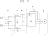
- FIG. 3 is a diagram illustrating a surge path in case where a protection capacitor is provided in accordance with an embodiment.
- a rectification unit 301 includes a first protection capacitor C5 and a second protection capacitor C6 connected between the live terminal L and the neutral terminal N.
- the first protection capacitor C5 and the second protection capacitor C6 are configured such that a value of the first impedance is smaller than a value of the second impedance, and are connected to each other in series on the first path ro1.
- first protection capacitor C5 is connected to the live terminal L and another end of the first capacitor C5 is connected to one end of the second protection capacitor C6. Further, another end of the second protection capacitor C6 is connected to the neutral terminal N.
- the first protection capacitor C5 and the second protection capacitor C6 are designed such that a value of the first impedance including a combined capacitance reactance value of the first protection capacitor C5 and the second protection capacitor C6 can be ignored compared to a value of the second impedance. That is, the capacitances of the first protection capacitor C5 and the second protection capacitor C6 are be designed such that the value of the first impedance is much smaller than the value of the second impedance.
- the surge flows only in the first path ro1. That is, since a surge current having an impedance in which harmonic noise due to a surge is relatively low is discharged through the first path ro1. This may result in improving surge immunity of the control unit 40 and the motor unit 50.
- inner spaces of the first motor M1 and the second motor M2 can be designed to be smaller than or equal to a reference inner space (e.g., 3 mm).
- FIGS. 2 and 3 illustrate only the first motor M1 in the motor unit 50, but the implementation is not limited thereto.
- the second motor M2 may be connected to the ground e.
- the power supply unit 10, the filter unit 20, and the rectification unit 30 have been described as separate configurations, the implementation is not limited thereto.
- the power supply unit 10, the filter unit 20, and the rectification unit 30 may alternatively be included in one configuration.
- the surge protection circuit 1 includes the first protection capacitor C5 and the second protection capacitor C6 which are provided in the rectification unit 301 and connected to each other in a manner that the first impedance value is smaller than the second impedance value. That is, since a surge current having an impedance in which harmonic noise due to a surge is relatively low is discharged through the first path ro1, by virtue of the first protection capacitor C5 and the second protection capacitor C6. This may result in improving surge immunity of the control unit 40 and the motor unit 50.
- the surge protection circuit 1 compared to the related art in which a circuit has been further provided in a motor drive circuit for surge protection, the surge protection circuit 1 according to the implementation which is equipped with only two capacitors can reduce a manufacturing cost of a product, and the inner spaces of the first motor M1 and the second motor M2 can be designed to be 3 mm or less, thereby reducing a volume of the surge protection circuit.
Landscapes
- Engineering & Computer Science (AREA)
- Power Engineering (AREA)
- Water Supply & Treatment (AREA)
- Inverter Devices (AREA)
- Control Of Ac Motors In General (AREA)
Description
- The present disclosure relates to a surge protection circuit and a dishwasher including the same, and one particular implementation relates to a surge protection circuit for protecting an electronic device from a surge, and a dishwasher including the same.
- In general, an Intelligent Power Module (IPM) is a module in which power semiconductor devices such as IGBT, MOSFET, and FRD, a control circuit, a drive circuit, a protection circuit, and a control power source are integrated into a single package, and is diversified in terms of input/output voltage and current, control method, shape, and size depending on use and/or requirements.
- Recently, an IPM with embedded IGBT, MOSFET and dedicated IC is mainly used in an electronic device including a motor. This does not mean that such control circuit and the like are not merely mounted in one module, but an optimal design comprehensively considering systems, devices, and control and protection functions is required.
- On the other hand, noise, surge, over-voltage or over-current is applied to the electronic device due to various external factors. This causes a problem of damaging the IPM and the motor.
- In the related art, in order to protect a motor from a surge, the motor is designed to have predetermined distances set between a motor cover and internal three-phase AC power lines. However, such a design has a problem of increasing a volume and a manufacturing cost of the motor.
- In the related art, in order to protect the motor from the surge, a logic circuit is further provided in a motor drive circuit. With this configuration, a warning signal is generated through feedback of a current detection circuit or through detection of a voltage of a power supply end using a Zener diode. The logic circuit is implemented as an operation short circuit or a high impedance according to the warning signal, so as to prevent generation of a surge voltage in a power supply line.
- However, such an additional logic circuit causes a problem of increasing a production cost and occupying a volume of a product.
- (Patent Literature 1)
US 6,949,906 B2 -
US 2015/003125 A1 relates to a power supply having a surge protection circuit for protecting a product from power surges. - The present disclosure is directed to overcoming those problems, namely, one aspect of an implementation is to protect an electronic device from an external surge.
- Another aspect of the present disclosure is to protect an electronic device from a surge without considering a volume of a motor and a manufacturing cost.
- The aspects to achieve in this disclosure are not limited to those aspects mentioned above, and other non-mentioned technical problems to be solved in this disclosure can be clearly understood by those skilled in the art by the following description.
- In order to achieve these and other advantages and in accordance with the purpose of this specification, as embodied and broadly described herein, there is provided a surge protection circuit according to
claim 1. The dependent claims relate to preferred embodiments. In accordance with one implementation of the present disclosure, there is provided a dishwasher according to claim 6. - An implementation according to the present disclosure has an effect of protecting an electronic device from an external surge.
- The implementation has an effect of designing a motor in a small volume.
- The implementation also has an effect of producing a surge protection circuit at a low cost.
-
-
FIG. 1 is a diagram illustrating a part of a configuration of a dishwasher including a surge protection circuit not covered by the literal wording of the claims. -
FIG. 2 is a diagram illustrating a surge path in case where a protection capacitor is not provided in accordance with an embodiment not covered by the literal wording of the claims. -
FIG. 3 is a diagram illustrating a surge path in case where a protection capacitor is provided in accordance with an embodiment. - Description will now be given in detail according to exemplary embodiments disclosed herein, with reference to the accompanying drawings. For the sake of brief description with reference to the drawings, the same or equivalent components may be provided with the same or similar reference numbers, and description thereof will not be repeated. In general, a suffix such as "module" and "unit" may be used to refer to elements or components. Use of such a suffix herein is merely intended to facilitate description of the specification, and the suffix itself is not intended to give any special meaning or function. In describing the present disclosure, if a detailed explanation for a related known function or construction is considered to unnecessarily divert the gist of the present disclosure, such explanation has been omitted but would be understood by those skilled in the art. The accompanying drawings are used to help easily understand the technical idea of the present disclosure and it should be understood that the idea of the present disclosure is not limited by the accompanying drawings. The idea of the present disclosure should be construed to extend to any alterations, equivalents and substitutes besides the accompanying drawings.
- It will be understood that although the terms first, second, etc. may be used herein to describe various elements, these elements should not be limited by these terms. These terms are generally only used to distinguish one element from another.
- It will be understood that when an element is referred to as being "connected with" another element, the element can be connected with the another element or intervening elements may also be present. In contrast, when an element is referred to as being "directly connected with" another element, there are no intervening elements present.
- A singular representation may include a plural representation unless it represents a definitely different meaning from the context.
- Terms such as "include" or "has" are used herein and should be understood that they are intended to indicate an existence of several components, functions or steps, disclosed in the specification, and it is also understood that greater or fewer components, functions, or steps may likewise be utilized.
- Hereinafter, a surge protection circuit according to an embodiment will be described with reference to
FIGS. 1 and 2 . -
FIG. 1 is a diagram illustrating a part of a configuration of a dishwasher including a surge protection circuit not covered by the literal wording of the claims. - Referring to
FIG. 1 , asurge protection circuit 1 includes apower supply unit 10, afilter unit 20, arectification unit 30, acontrol unit 40, and amotor unit 50. - The
power supply unit 10 supplies power required to operate a dishwasher from a commercial power source or an external power source. Thepower supply unit 10 may include a cord p through which alternating current (AC) power is received from the commercial power source, and a cord reel (not illustrated) on which the cord is wound. - Specifically, the
power supply unit 10 may include a live terminal L and a neutral terminal N, so that commercial AC power can be applied from the power cord p to the live terminal L and the neutral terminal N. - The
filter unit 20 includes a first capacitor C1 and a second capacitor C2 connected between the live terminal L and the neutral terminal N, and a ground e is connected to a node between the first capacitor C1 and the second capacitor C3 so that a surge is applied to thefilter unit 20 through the ground e. - The
filter unit 20 is configured to filter noise from commercial power of thepower supply unit 10. Specifically, thefilter unit 20 may be a Y capacitor implemented by the first capacitor C1 and the second capacitor C2, and the Y capacitor is a capacitor for shielding common mode (CM) noise. - Here, the common mode noise is noise that enters the
surge protection circuit 1 through the ground e, and a detailed description of the Y capacitor is omitted. - The
rectification unit 30 includes adiode part 31 and a third capacitor C3, and is configured to rectify AC power, from which noise has been removed, into direct current (DC) power. - The
diode part 31 may be a bridge diode including a plurality of diodes, and the number of diodes included may be determined depending on the commercial power applied. For example, if the commercial AC power is single-phase AC power, four diodes may be configured in a bridge form. On the other hand, if the commercial AC power is three-phase AC power, six diodes may be configured in a bridge form. However, the present disclosure is not limited thereto. - The third capacitor C3 may be a constant voltage capacitor that is connected between the live terminal Land the neutral terminal N, and configured to suppress sudden voltage fluctuation, and remove a high frequency signal so as to maintain a constant voltage of DC power.
- The
control unit 40 is configured to control themotor unit 50 so that the dishwasher performs operations such as water supply, washing, and draining. Thecontrol unit 40 includes an IPM and a fourth capacitor C4 (seeFIG. 2 ). - The IPM includes an
internal logic circuit 41 and is configured to generate driving power, in response to an operation mode such as water supply to a first motor M1 and a second motor M2, washing, draining, or the like, and apply the generated driving power to themotor unit 50. - The
internal logic circuit 41 is configured to control switching operations of switches (not illustrated), which are connected to the first motor M1 and the second motor M2, to drive the first motor M1 and the second motor M2 according to a signal from a Micom (not illustrated). - For convenience of explanation, the
internal logic circuit 41 is described as controlling the switching operations of the switches connected to the first motor M1 and the second motor M2, but the disclosure is not limited thereto. - The fourth capacitor C4 may be connected between the
internal logic circuit 41 and themotor unit 50. The fourth capacitor C4 may be a capacitor, namely, a bootstrap capacitor for a floating ground to allow bootstrapping to be applied to a gate capacitor (not illustrated) connected to a switch, for example, a gate of a transistor for driving the first motor M1 and the second motor M2. - For convenience of description,
FIG. 2 illustrates that the fourth capacitor is connected only to a first power line u among three-phase power lines, but the implementation is not limited thereto, and bootstrap capacitors may alternatively be connected to a second power line v and a third power line w, respectively. - The
motor unit 50 includes a first motor M1 and a second motor M2, and the first motor M1 and the second motor M2 may be 3-phase motors. - Each of the first motor M1 and the second motor M2 includes a stator and a rotor. AC power of a phase corresponding to a predetermined frequency is applied to a coil of the stator corresponding to the phase. Accordingly, the rotor is rotated by those three-phase power u, v, and W applied to the respectively coils through the power lines.
- Each of the first motor M1 and the second motor M2 may be, for example, a Surface-Mounted Permanent-Magnet Synchronous Motor (SMPMSM), an Interior Permanent Magnet Synchronous Motor (IPMSM), a Synchronous Reluctance Motor (Synrm), or the like, but the implementation is not limited thereto.
- The first motor M1 and the second motor M2 are motors used for performing strokes, for example, water supply, washing, draining, and the like of the dishwasher, and may operate under the control of the
control unit 40. - Hereinafter, a path of a common mode surge will be described with reference to
FIG. 2 . -
FIG. 2 is a diagram illustrating a surge path in case where a protection capacitor is not provided not covered by the literal wording of the claims. - Referring to
FIG. 2 , a common mode (CM) surge (hereinafter, referred to as a surge) is applied through the ground e of thefilter unit 20. The surge may partially flow through a first path ro1 (hereinafter, referred to as a first surge), and the remaining of the surge may flow through a second path ro2 (hereinafter, referred to as a second surge). That is, the surge may be divided into the first surge and the second surge to correspond to a combined impedance (hereinafter, referred to as a first impedance) of thefilter unit 20 and therectification unit 30, and a combined impedance (hereinafter, referred to as a second impedance) of thecontrol unit 40 and themotor unit 50. - The second surge may cause the first motor M1 and the IPM to be burnt. In order to prevent such burnout of the
motor unit 50 and the IPM due to the second surge, at least one capacitor may be further provided on the first path ro1 to reduce the second surge flowing to thecontrol unit 40 and themotor unit 50. That is, by further providing at least one protection capacitor on the first path ro1, an impedance value of the first impedance can be lowered so that a surge current flows only in the first path ro1. - Hereinafter, a rectification unit including a protection capacitor I according to an implementation will be described with reference to
FIG. 3 . -
FIG. 3 is a diagram illustrating a surge path in case where a protection capacitor is provided in accordance with an embodiment. - Referring to
FIG. 3 , arectification unit 301 according to an implementation includes a first protection capacitor C5 and a second protection capacitor C6 connected between the live terminal L and the neutral terminal N. The first protection capacitor C5 and the second protection capacitor C6 are configured such that a value of the first impedance is smaller than a value of the second impedance, and are connected to each other in series on the first path ro1. - Specifically, one end of the first protection capacitor C5 is connected to the live terminal L and another end of the first capacitor C5 is connected to one end of the second protection capacitor C6. Further, another end of the second protection capacitor C6 is connected to the neutral terminal N.
- Here, the first protection capacitor C5 and the second protection capacitor C6 are designed such that a value of the first impedance including a combined capacitance reactance value of the first protection capacitor C5 and the second protection capacitor C6 can be ignored compared to a value of the second impedance. That is, the capacitances of the first protection capacitor C5 and the second protection capacitor C6 are be designed such that the value of the first impedance is much smaller than the value of the second impedance.
- Therefore, as illustrated in
FIG. 3 , the surge flows only in the first path ro1. That is, since a surge current having an impedance in which harmonic noise due to a surge is relatively low is discharged through the first path ro1. This may result in improving surge immunity of thecontrol unit 40 and themotor unit 50. - Accordingly, since no surge flows through the second path ro2 including the first motor M1 and the second motor M2, inner spaces of the first motor M1 and the second motor M2 can be designed to be smaller than or equal to a reference inner space (e.g., 3 mm).
- For convenience of explanation,
FIGS. 2 and3 illustrate only the first motor M1 in themotor unit 50, but the implementation is not limited thereto. The second motor M2 may be connected to the ground e. - In addition, although the
power supply unit 10, thefilter unit 20, and therectification unit 30 have been described as separate configurations, the implementation is not limited thereto. Thepower supply unit 10, thefilter unit 20, and therectification unit 30 may alternatively be included in one configuration. - As described above, the
surge protection circuit 1 according to the implementation includes the first protection capacitor C5 and the second protection capacitor C6 which are provided in therectification unit 301 and connected to each other in a manner that the first impedance value is smaller than the second impedance value. That is, since a surge current having an impedance in which harmonic noise due to a surge is relatively low is discharged through the first path ro1, by virtue of the first protection capacitor C5 and the second protection capacitor C6. This may result in improving surge immunity of thecontrol unit 40 and themotor unit 50. - Therefore, compared to the related art in which a circuit has been further provided in a motor drive circuit for surge protection, the
surge protection circuit 1 according to the implementation which is equipped with only two capacitors can reduce a manufacturing cost of a product, and the inner spaces of the first motor M1 and the second motor M2 can be designed to be 3 mm or less, thereby reducing a volume of the surge protection circuit. - Although the implementations of the present disclosure have been described in detail above, the scope of the present disclosure is not limited thereto, and various modifications and improvements made by those skilled in the art using the basic concept of the present disclosure defined in the following claims of the present disclosure will also belong to the claims of the present disclosure. Therefore, it should also be understood that the above-described embodiments are not limited by any of the details of the foregoing description, unless otherwise specified, but rather should be construed broadly within its scope as defined in the appended claims, Therefore, all changes and modifications that fall within the metes and bounds of the claims, or equivalents of such metes and bounds are therefore intended to be embraced by the appended claims.
Claims (5)
- A surge protection circuit (1), comprising:a power supply unit (10) to which first power is applied;a filter unit (20) configured to filter noise of the first power while a current corresponding to a surge flowing therethrough;a rectification unit (301) provided with a diode part (31) and at least one protection capacitor (C5, C6), and configured to rectify the first power into second power,a control unit (40) configured to generate driving power using the second power according to the operation mode; anda motor unit (50) provided with at least one motor (M1, M2) controlled by the control unit (40) according to the operation mode and configured to be driven by the driving power,wherein the surge protection circuit (1) is characterized in that:the filter unit (20) is connected with a ground so that the current is applied to the filter unit (20) through the ground,wherein a first impedance in which impedance of the filter unit (20) and impedance of the rectification unit (301) are combined is smaller than a second impedance in which impedance of the control unit (40) and impedance of the motor unit (50) are combined,wherein the first power is alternating current, AC, power applied through a live terminal (L) and a neutral terminal (N),wherein the filter unit (20) is provided with a first capacitor (C1) and a second capacitor (C2) connected in series between the live terminal (L) and the neutral terminal (N),wherein the ground is connected to a node between the first capacitor (C1) and the second capacitor (C2),wherein the rectification unit (301) is provided with a third capacitor (C3), a first protection capacitor (C5), and a second protection capacitor (C6) connected between the live terminal (L) and the neutral terminal (N),wherein the current corresponding to the surge flows along a path configured by the ground and the first to third capacitors (C1 to C3), the first protection capacitor (C5) and the second protection capacitor (C6),wherein the third capacitor (C3) is connected in parallel between the diode part (31) and the control unit (40),wherein one end of the first protection capacitor (C5) is connected to the live terminal (L) between the diode part (31) and the control unit (40), another end of the first protection capacitor (C5) is connected to one end of the second protection capacitor (C6) and another end of the second protection capacitor (C6) is connected to the neutral terminal (N) between the filter unit (20) and the diode part (31), andwherein the third capacitor (C3) is connected in parallel with the first protection capacitor (C5) and the second protection capacitor (C6).
- The surge protection circuit (1) of claim 1, wherein the control unit (40) comprises:an Intelligent Power Module, IPM, configured to apply the driving power to the at least one motor (M1, M2) according to the operation mode; anda fourth capacitor (C4) connected to the IPM and a power line of the at least one motor (M1, M2).
- The surge protection circuit (1) of claim 2, wherein the fourth capacitor (C4) is a capacitor performing bootstrapping for driving the at least one motor (M1, M2),wherein the operation mode is one of water supply, washing, and draining modes, andwherein the IPM is configured to apply the driving power to the at least one motor (M1, M2), in response to one of the water supply, washing, and draining modes.
- The surge protection circuit (1) of claim 3, wherein the motor unit (50) comprises a first motor (M1) and a second motor (M2), and
wherein the IPM is configured to apply the driving power to the first motor (M1) or the second motor (M2), in response to one of the water supply, washing, and draining modes. - A dishwasher comprising a surge protection circuit (1) according to any one of claims 1 to 4.
Applications Claiming Priority (1)
| Application Number | Priority Date | Filing Date | Title |
|---|---|---|---|
| KR1020190070908A KR102745006B1 (en) | 2019-06-14 | 2019-06-14 | Surge protect circuit and dishwasher including surge protect circuit |
Publications (2)
| Publication Number | Publication Date |
|---|---|
| EP3751690A1 EP3751690A1 (en) | 2020-12-16 |
| EP3751690B1 true EP3751690B1 (en) | 2024-08-28 |
Family
ID=71094107
Family Applications (1)
| Application Number | Title | Priority Date | Filing Date |
|---|---|---|---|
| EP20179605.9A Active EP3751690B1 (en) | 2019-06-14 | 2020-06-12 | Surge protection circuit and dishwasher including the same |
Country Status (3)
| Country | Link |
|---|---|
| US (1) | US11296495B2 (en) |
| EP (1) | EP3751690B1 (en) |
| KR (1) | KR102745006B1 (en) |
Families Citing this family (2)
| Publication number | Priority date | Publication date | Assignee | Title |
|---|---|---|---|---|
| CN113488977B (en) * | 2021-07-12 | 2023-06-13 | 珠海格力电器股份有限公司 | Hot plug protection device of motor and motor |
| TWI827379B (en) | 2022-11-23 | 2023-12-21 | 財團法人工業技術研究院 | Motor controller and motor control method for an electric vehicle |
Family Cites Families (12)
| Publication number | Priority date | Publication date | Assignee | Title |
|---|---|---|---|---|
| US4843515A (en) * | 1987-04-20 | 1989-06-27 | Keytek Instrument Corp. | Surge undershoot eliminator |
| EP1258980B1 (en) * | 2001-05-17 | 2005-12-07 | STMicroelectronics S.r.l. | "Driving circuit and method for preventing voltage surges on supply lines while driving a dc motor" |
| US7940506B2 (en) * | 2003-03-05 | 2011-05-10 | Dollar Energy Group, Inc. | Automated AC line filter and surge suppression apparatus and method |
| EP2360820B1 (en) | 2009-12-31 | 2018-03-28 | Nxp B.V. | Surge protection circuit |
| US8520355B2 (en) * | 2010-07-27 | 2013-08-27 | Regal Beloit America, Inc. | Methods and systems for transient voltage protection |
| KR20130081727A (en) * | 2011-12-28 | 2013-07-18 | 삼성전기주식회사 | Power supply apparatus including a function of protecting over-voltage |
| KR101474150B1 (en) * | 2013-07-01 | 2014-12-18 | 삼성전기주식회사 | Power supply having surge protection circuit |
| KR20150052446A (en) * | 2013-11-05 | 2015-05-14 | 주식회사 아모센스 | Protection Circuit for Power Supply |
| KR101608135B1 (en) * | 2014-05-22 | 2016-03-31 | 루멘전광 주식회사 | LED Driving Circuit For Radiation Area |
| KR101728415B1 (en) * | 2015-06-25 | 2017-04-28 | (주)엠포스 | Ac direct-type led lighting circuit with protection |
| KR20170076266A (en) * | 2015-12-24 | 2017-07-04 | 주식회사 젬 | Protection Circuit for Power Supply |
| KR102379057B1 (en) * | 2017-08-21 | 2022-03-28 | 현대자동차주식회사 | ACTIVE EMI(Electro-Magnetic Interference) FILTER AND VEHICLE HAVING THE SAME |
-
2019
- 2019-06-14 KR KR1020190070908A patent/KR102745006B1/en active Active
-
2020
- 2020-06-12 US US16/900,032 patent/US11296495B2/en active Active
- 2020-06-12 EP EP20179605.9A patent/EP3751690B1/en active Active
Also Published As
| Publication number | Publication date |
|---|---|
| EP3751690A1 (en) | 2020-12-16 |
| US20200395749A1 (en) | 2020-12-17 |
| US11296495B2 (en) | 2022-04-05 |
| KR20200143070A (en) | 2020-12-23 |
| KR102745006B1 (en) | 2024-12-20 |
Similar Documents
| Publication | Publication Date | Title |
|---|---|---|
| CN102668364B (en) | Avoiding Load Dump Overvoltage in Synchronous Rectifiers | |
| JP5444142B2 (en) | Power converter and motor drive device using the same | |
| US20130049659A1 (en) | Circuit arrangement for modular drive power converters | |
| CN109417354B (en) | Three-level inverter | |
| US11296495B2 (en) | Surge protection circuit and dishwasher including the same | |
| JP3582545B2 (en) | Bridge type power converter | |
| JP7537183B2 (en) | Semiconductor Device | |
| CN107949980B (en) | Voltage converter, electric drive system and method for reducing interference voltages | |
| US9374006B2 (en) | Three-channel high-side gate driver having startup circuit and configurable outputs | |
| JP2022077909A (en) | Semiconductor device | |
| EP3566293B1 (en) | Grounding scheme for power converters with silicon carbide mosfets and method | |
| CN108521843A (en) | Filtering arranges | |
| CN107636944B (en) | Motor system and control method thereof | |
| CN205081635U (en) | A device for reducing and/or harmful shaft current among to avoid electrical | |
| US6008560A (en) | Inverter driven motor having winding termination reducing EMI | |
| JP7003449B2 (en) | In-vehicle device | |
| JP7086268B2 (en) | Rotating machine, drive device of rotating machine, and drive system of rotating machine | |
| KR100546430B1 (en) | Load-side filter device for conversion circuit device | |
| JP2003324966A (en) | Inverter drive circuit | |
| US7030587B2 (en) | Configuration of converter switches and machine coils of a switched reluctance machine | |
| CN101346874B (en) | Rotating electrical machine with decoupled phases | |
| KR20200143065A (en) | Surge protect circuit and dishwasher including surge protect circuit | |
| JP4904851B2 (en) | Semiconductor device with overvoltage protection circuit | |
| WO2017158783A1 (en) | Power conversion device and air conditioning device using same | |
| US20220038043A1 (en) | Electromagnetic filtering of a control circuit of an electric motor |
Legal Events
| Date | Code | Title | Description |
|---|---|---|---|
| PUAI | Public reference made under article 153(3) epc to a published international application that has entered the european phase |
Free format text: ORIGINAL CODE: 0009012 |
|
| STAA | Information on the status of an ep patent application or granted ep patent |
Free format text: STATUS: THE APPLICATION HAS BEEN PUBLISHED |
|
| AK | Designated contracting states |
Kind code of ref document: A1 Designated state(s): AL AT BE BG CH CY CZ DE DK EE ES FI FR GB GR HR HU IE IS IT LI LT LU LV MC MK MT NL NO PL PT RO RS SE SI SK SM TR |
|
| AX | Request for extension of the european patent |
Extension state: BA ME |
|
| STAA | Information on the status of an ep patent application or granted ep patent |
Free format text: STATUS: REQUEST FOR EXAMINATION WAS MADE |
|
| 17P | Request for examination filed |
Effective date: 20210614 |
|
| RBV | Designated contracting states (corrected) |
Designated state(s): AL AT BE BG CH CY CZ DE DK EE ES FI FR GB GR HR HU IE IS IT LI LT LU LV MC MK MT NL NO PL PT RO RS SE SI SK SM TR |
|
| STAA | Information on the status of an ep patent application or granted ep patent |
Free format text: STATUS: EXAMINATION IS IN PROGRESS |
|
| 17Q | First examination report despatched |
Effective date: 20220809 |
|
| GRAP | Despatch of communication of intention to grant a patent |
Free format text: ORIGINAL CODE: EPIDOSNIGR1 |
|
| STAA | Information on the status of an ep patent application or granted ep patent |
Free format text: STATUS: GRANT OF PATENT IS INTENDED |
|
| INTG | Intention to grant announced |
Effective date: 20240410 |
|
| GRAS | Grant fee paid |
Free format text: ORIGINAL CODE: EPIDOSNIGR3 |
|
| GRAA | (expected) grant |
Free format text: ORIGINAL CODE: 0009210 |
|
| STAA | Information on the status of an ep patent application or granted ep patent |
Free format text: STATUS: THE PATENT HAS BEEN GRANTED |
|
| AK | Designated contracting states |
Kind code of ref document: B1 Designated state(s): AL AT BE BG CH CY CZ DE DK EE ES FI FR GB GR HR HU IE IS IT LI LT LU LV MC MK MT NL NO PL PT RO RS SE SI SK SM TR |
|
| REG | Reference to a national code |
Ref country code: CH Ref legal event code: EP |
|
| REG | Reference to a national code |
Ref country code: DE Ref legal event code: R096 Ref document number: 602020036522 Country of ref document: DE |
|
| REG | Reference to a national code |
Ref country code: IE Ref legal event code: FG4D |
|
| REG | Reference to a national code |
Ref country code: LT Ref legal event code: MG9D |
|
| PG25 | Lapsed in a contracting state [announced via postgrant information from national office to epo] |
Ref country code: NO Free format text: LAPSE BECAUSE OF FAILURE TO SUBMIT A TRANSLATION OF THE DESCRIPTION OR TO PAY THE FEE WITHIN THE PRESCRIBED TIME-LIMIT Effective date: 20241128 |
|
| REG | Reference to a national code |
Ref country code: AT Ref legal event code: MK05 Ref document number: 1719043 Country of ref document: AT Kind code of ref document: T Effective date: 20240828 |
|
| PG25 | Lapsed in a contracting state [announced via postgrant information from national office to epo] |
Ref country code: NL Free format text: LAPSE BECAUSE OF FAILURE TO SUBMIT A TRANSLATION OF THE DESCRIPTION OR TO PAY THE FEE WITHIN THE PRESCRIBED TIME-LIMIT Effective date: 20240828 Ref country code: FI Free format text: LAPSE BECAUSE OF FAILURE TO SUBMIT A TRANSLATION OF THE DESCRIPTION OR TO PAY THE FEE WITHIN THE PRESCRIBED TIME-LIMIT Effective date: 20240828 Ref country code: PT Free format text: LAPSE BECAUSE OF FAILURE TO SUBMIT A TRANSLATION OF THE DESCRIPTION OR TO PAY THE FEE WITHIN THE PRESCRIBED TIME-LIMIT Effective date: 20241230 Ref country code: GR Free format text: LAPSE BECAUSE OF FAILURE TO SUBMIT A TRANSLATION OF THE DESCRIPTION OR TO PAY THE FEE WITHIN THE PRESCRIBED TIME-LIMIT Effective date: 20241129 Ref country code: PL Free format text: LAPSE BECAUSE OF FAILURE TO SUBMIT A TRANSLATION OF THE DESCRIPTION OR TO PAY THE FEE WITHIN THE PRESCRIBED TIME-LIMIT Effective date: 20240828 |
|
| PG25 | Lapsed in a contracting state [announced via postgrant information from national office to epo] |
Ref country code: BG Free format text: LAPSE BECAUSE OF FAILURE TO SUBMIT A TRANSLATION OF THE DESCRIPTION OR TO PAY THE FEE WITHIN THE PRESCRIBED TIME-LIMIT Effective date: 20240828 |
|
| PG25 | Lapsed in a contracting state [announced via postgrant information from national office to epo] |
Ref country code: LV Free format text: LAPSE BECAUSE OF FAILURE TO SUBMIT A TRANSLATION OF THE DESCRIPTION OR TO PAY THE FEE WITHIN THE PRESCRIBED TIME-LIMIT Effective date: 20240828 |
|
| REG | Reference to a national code |
Ref country code: NL Ref legal event code: MP Effective date: 20240828 |
|
| PG25 | Lapsed in a contracting state [announced via postgrant information from national office to epo] |
Ref country code: IS Free format text: LAPSE BECAUSE OF FAILURE TO SUBMIT A TRANSLATION OF THE DESCRIPTION OR TO PAY THE FEE WITHIN THE PRESCRIBED TIME-LIMIT Effective date: 20241228 Ref country code: AT Free format text: LAPSE BECAUSE OF FAILURE TO SUBMIT A TRANSLATION OF THE DESCRIPTION OR TO PAY THE FEE WITHIN THE PRESCRIBED TIME-LIMIT Effective date: 20240828 |
|
| PG25 | Lapsed in a contracting state [announced via postgrant information from national office to epo] |
Ref country code: HR Free format text: LAPSE BECAUSE OF FAILURE TO SUBMIT A TRANSLATION OF THE DESCRIPTION OR TO PAY THE FEE WITHIN THE PRESCRIBED TIME-LIMIT Effective date: 20240828 |
|
| PG25 | Lapsed in a contracting state [announced via postgrant information from national office to epo] |
Ref country code: ES Free format text: LAPSE BECAUSE OF FAILURE TO SUBMIT A TRANSLATION OF THE DESCRIPTION OR TO PAY THE FEE WITHIN THE PRESCRIBED TIME-LIMIT Effective date: 20240828 Ref country code: RS Free format text: LAPSE BECAUSE OF FAILURE TO SUBMIT A TRANSLATION OF THE DESCRIPTION OR TO PAY THE FEE WITHIN THE PRESCRIBED TIME-LIMIT Effective date: 20241128 |
|
| PG25 | Lapsed in a contracting state [announced via postgrant information from national office to epo] |
Ref country code: RS Free format text: LAPSE BECAUSE OF FAILURE TO SUBMIT A TRANSLATION OF THE DESCRIPTION OR TO PAY THE FEE WITHIN THE PRESCRIBED TIME-LIMIT Effective date: 20241128 Ref country code: PT Free format text: LAPSE BECAUSE OF FAILURE TO SUBMIT A TRANSLATION OF THE DESCRIPTION OR TO PAY THE FEE WITHIN THE PRESCRIBED TIME-LIMIT Effective date: 20241230 Ref country code: PL Free format text: LAPSE BECAUSE OF FAILURE TO SUBMIT A TRANSLATION OF THE DESCRIPTION OR TO PAY THE FEE WITHIN THE PRESCRIBED TIME-LIMIT Effective date: 20240828 Ref country code: NO Free format text: LAPSE BECAUSE OF FAILURE TO SUBMIT A TRANSLATION OF THE DESCRIPTION OR TO PAY THE FEE WITHIN THE PRESCRIBED TIME-LIMIT Effective date: 20241128 Ref country code: NL Free format text: LAPSE BECAUSE OF FAILURE TO SUBMIT A TRANSLATION OF THE DESCRIPTION OR TO PAY THE FEE WITHIN THE PRESCRIBED TIME-LIMIT Effective date: 20240828 Ref country code: LV Free format text: LAPSE BECAUSE OF FAILURE TO SUBMIT A TRANSLATION OF THE DESCRIPTION OR TO PAY THE FEE WITHIN THE PRESCRIBED TIME-LIMIT Effective date: 20240828 Ref country code: IS Free format text: LAPSE BECAUSE OF FAILURE TO SUBMIT A TRANSLATION OF THE DESCRIPTION OR TO PAY THE FEE WITHIN THE PRESCRIBED TIME-LIMIT Effective date: 20241228 Ref country code: HR Free format text: LAPSE BECAUSE OF FAILURE TO SUBMIT A TRANSLATION OF THE DESCRIPTION OR TO PAY THE FEE WITHIN THE PRESCRIBED TIME-LIMIT Effective date: 20240828 Ref country code: GR Free format text: LAPSE BECAUSE OF FAILURE TO SUBMIT A TRANSLATION OF THE DESCRIPTION OR TO PAY THE FEE WITHIN THE PRESCRIBED TIME-LIMIT Effective date: 20241129 Ref country code: FI Free format text: LAPSE BECAUSE OF FAILURE TO SUBMIT A TRANSLATION OF THE DESCRIPTION OR TO PAY THE FEE WITHIN THE PRESCRIBED TIME-LIMIT Effective date: 20240828 Ref country code: ES Free format text: LAPSE BECAUSE OF FAILURE TO SUBMIT A TRANSLATION OF THE DESCRIPTION OR TO PAY THE FEE WITHIN THE PRESCRIBED TIME-LIMIT Effective date: 20240828 Ref country code: BG Free format text: LAPSE BECAUSE OF FAILURE TO SUBMIT A TRANSLATION OF THE DESCRIPTION OR TO PAY THE FEE WITHIN THE PRESCRIBED TIME-LIMIT Effective date: 20240828 Ref country code: AT Free format text: LAPSE BECAUSE OF FAILURE TO SUBMIT A TRANSLATION OF THE DESCRIPTION OR TO PAY THE FEE WITHIN THE PRESCRIBED TIME-LIMIT Effective date: 20240828 |
|
| PG25 | Lapsed in a contracting state [announced via postgrant information from national office to epo] |
Ref country code: SM Free format text: LAPSE BECAUSE OF FAILURE TO SUBMIT A TRANSLATION OF THE DESCRIPTION OR TO PAY THE FEE WITHIN THE PRESCRIBED TIME-LIMIT Effective date: 20240828 Ref country code: RO Free format text: LAPSE BECAUSE OF FAILURE TO SUBMIT A TRANSLATION OF THE DESCRIPTION OR TO PAY THE FEE WITHIN THE PRESCRIBED TIME-LIMIT Effective date: 20240828 Ref country code: DK Free format text: LAPSE BECAUSE OF FAILURE TO SUBMIT A TRANSLATION OF THE DESCRIPTION OR TO PAY THE FEE WITHIN THE PRESCRIBED TIME-LIMIT Effective date: 20240828 |
|
| PG25 | Lapsed in a contracting state [announced via postgrant information from national office to epo] |
Ref country code: EE Free format text: LAPSE BECAUSE OF FAILURE TO SUBMIT A TRANSLATION OF THE DESCRIPTION OR TO PAY THE FEE WITHIN THE PRESCRIBED TIME-LIMIT Effective date: 20240828 |
|
| PG25 | Lapsed in a contracting state [announced via postgrant information from national office to epo] |
Ref country code: CZ Free format text: LAPSE BECAUSE OF FAILURE TO SUBMIT A TRANSLATION OF THE DESCRIPTION OR TO PAY THE FEE WITHIN THE PRESCRIBED TIME-LIMIT Effective date: 20240828 |
|
| PG25 | Lapsed in a contracting state [announced via postgrant information from national office to epo] |
Ref country code: IT Free format text: LAPSE BECAUSE OF FAILURE TO SUBMIT A TRANSLATION OF THE DESCRIPTION OR TO PAY THE FEE WITHIN THE PRESCRIBED TIME-LIMIT Effective date: 20240828 Ref country code: SK Free format text: LAPSE BECAUSE OF FAILURE TO SUBMIT A TRANSLATION OF THE DESCRIPTION OR TO PAY THE FEE WITHIN THE PRESCRIBED TIME-LIMIT Effective date: 20240828 |
|
| REG | Reference to a national code |
Ref country code: DE Ref legal event code: R097 Ref document number: 602020036522 Country of ref document: DE |
|
| PLBE | No opposition filed within time limit |
Free format text: ORIGINAL CODE: 0009261 |
|
| STAA | Information on the status of an ep patent application or granted ep patent |
Free format text: STATUS: NO OPPOSITION FILED WITHIN TIME LIMIT |
|
| PGFP | Annual fee paid to national office [announced via postgrant information from national office to epo] |
Ref country code: DE Payment date: 20250508 Year of fee payment: 6 |
|
| 26N | No opposition filed |
Effective date: 20250530 |
|
| PG25 | Lapsed in a contracting state [announced via postgrant information from national office to epo] |
Ref country code: SE Free format text: LAPSE BECAUSE OF FAILURE TO SUBMIT A TRANSLATION OF THE DESCRIPTION OR TO PAY THE FEE WITHIN THE PRESCRIBED TIME-LIMIT Effective date: 20240828 |
|
| REG | Reference to a national code |
Ref country code: CH Ref legal event code: H13 Free format text: ST27 STATUS EVENT CODE: U-0-0-H10-H13 (AS PROVIDED BY THE NATIONAL OFFICE) Effective date: 20260127 |
|
| PG25 | Lapsed in a contracting state [announced via postgrant information from national office to epo] |
Ref country code: MC Free format text: LAPSE BECAUSE OF FAILURE TO SUBMIT A TRANSLATION OF THE DESCRIPTION OR TO PAY THE FEE WITHIN THE PRESCRIBED TIME-LIMIT Effective date: 20240828 |
|
| PG25 | Lapsed in a contracting state [announced via postgrant information from national office to epo] |
Ref country code: LU Free format text: LAPSE BECAUSE OF NON-PAYMENT OF DUE FEES Effective date: 20250612 |
|
| GBPC | Gb: european patent ceased through non-payment of renewal fee |
Effective date: 20250612 |
|
| REG | Reference to a national code |
Ref country code: BE Ref legal event code: MM Effective date: 20250630 |
|
| PG25 | Lapsed in a contracting state [announced via postgrant information from national office to epo] |
Ref country code: GB Free format text: LAPSE BECAUSE OF NON-PAYMENT OF DUE FEES Effective date: 20250612 |
|
| PG25 | Lapsed in a contracting state [announced via postgrant information from national office to epo] |
Ref country code: IE Free format text: LAPSE BECAUSE OF NON-PAYMENT OF DUE FEES Effective date: 20250612 |
|
| PG25 | Lapsed in a contracting state [announced via postgrant information from national office to epo] |
Ref country code: BE Free format text: LAPSE BECAUSE OF NON-PAYMENT OF DUE FEES Effective date: 20250630 |
|
| PG25 | Lapsed in a contracting state [announced via postgrant information from national office to epo] |
Ref country code: FR Free format text: LAPSE BECAUSE OF NON-PAYMENT OF DUE FEES Effective date: 20250630 |
|
| PG25 | Lapsed in a contracting state [announced via postgrant information from national office to epo] |
Ref country code: CH Free format text: LAPSE BECAUSE OF NON-PAYMENT OF DUE FEES Effective date: 20250630 |