EP3751653A1 - Anode layer activation method for solid oxide fuel cell, and solid oxide fuel cell system - Google Patents
Anode layer activation method for solid oxide fuel cell, and solid oxide fuel cell system Download PDFInfo
- Publication number
- EP3751653A1 EP3751653A1 EP18904625.3A EP18904625A EP3751653A1 EP 3751653 A1 EP3751653 A1 EP 3751653A1 EP 18904625 A EP18904625 A EP 18904625A EP 3751653 A1 EP3751653 A1 EP 3751653A1
- Authority
- EP
- European Patent Office
- Prior art keywords
- anode layer
- containing gas
- fuel cell
- solid oxide
- oxygen
- Prior art date
- Legal status (The legal status is an assumption and is not a legal conclusion. Google has not performed a legal analysis and makes no representation as to the accuracy of the status listed.)
- Pending
Links
- 239000000446 fuel Substances 0.000 title claims abstract description 119
- 238000000034 method Methods 0.000 title claims abstract description 62
- 239000007787 solid Substances 0.000 title claims abstract description 50
- 230000004913 activation Effects 0.000 title claims abstract description 39
- 239000007789 gas Substances 0.000 claims abstract description 204
- PXHVJJICTQNCMI-UHFFFAOYSA-N Nickel Chemical compound [Ni] PXHVJJICTQNCMI-UHFFFAOYSA-N 0.000 claims abstract description 141
- QVGXLLKOCUKJST-UHFFFAOYSA-N atomic oxygen Chemical compound [O] QVGXLLKOCUKJST-UHFFFAOYSA-N 0.000 claims abstract description 90
- 239000001301 oxygen Substances 0.000 claims abstract description 90
- 229910052760 oxygen Inorganic materials 0.000 claims abstract description 90
- 229910052751 metal Inorganic materials 0.000 claims abstract description 72
- 239000002184 metal Substances 0.000 claims abstract description 72
- 229910052759 nickel Inorganic materials 0.000 claims abstract description 69
- UFHFLCQGNIYNRP-UHFFFAOYSA-N Hydrogen Chemical compound [H][H] UFHFLCQGNIYNRP-UHFFFAOYSA-N 0.000 claims abstract description 64
- 239000001257 hydrogen Substances 0.000 claims abstract description 64
- 229910052739 hydrogen Inorganic materials 0.000 claims abstract description 64
- 239000003792 electrolyte Substances 0.000 claims abstract description 32
- 230000003213 activating effect Effects 0.000 claims abstract description 11
- 238000007254 oxidation reaction Methods 0.000 claims description 46
- 230000003647 oxidation Effects 0.000 claims description 41
- 239000011230 binding agent Substances 0.000 claims description 23
- 230000008569 process Effects 0.000 claims description 22
- 239000000470 constituent Substances 0.000 claims description 12
- 239000011261 inert gas Substances 0.000 claims description 12
- XLYOFNOQVPJJNP-UHFFFAOYSA-N water Substances O XLYOFNOQVPJJNP-UHFFFAOYSA-N 0.000 claims description 11
- 230000001590 oxidative effect Effects 0.000 claims description 10
- 230000009467 reduction Effects 0.000 claims description 9
- 238000011946 reduction process Methods 0.000 claims description 5
- 238000010494 dissociation reaction Methods 0.000 claims description 2
- 208000018459 dissociative disease Diseases 0.000 claims description 2
- 238000001994 activation Methods 0.000 description 77
- 229910000480 nickel oxide Inorganic materials 0.000 description 17
- 238000006722 reduction reaction Methods 0.000 description 15
- 230000006872 improvement Effects 0.000 description 12
- 239000000463 material Substances 0.000 description 12
- GNRSAWUEBMWBQH-UHFFFAOYSA-N oxonickel Chemical compound [Ni]=O GNRSAWUEBMWBQH-UHFFFAOYSA-N 0.000 description 12
- 238000010304 firing Methods 0.000 description 9
- 238000006243 chemical reaction Methods 0.000 description 8
- 230000007423 decrease Effects 0.000 description 8
- 238000010586 diagram Methods 0.000 description 8
- 150000002500 ions Chemical class 0.000 description 8
- 238000010248 power generation Methods 0.000 description 8
- 230000000694 effects Effects 0.000 description 6
- 239000003054 catalyst Substances 0.000 description 5
- 239000003795 chemical substances by application Substances 0.000 description 5
- 230000020411 cell activation Effects 0.000 description 4
- 239000002737 fuel gas Substances 0.000 description 4
- HEZMWWAKWCSUCB-PHDIDXHHSA-N (3R,4R)-3,4-dihydroxycyclohexa-1,5-diene-1-carboxylic acid Chemical compound O[C@@H]1C=CC(C(O)=O)=C[C@H]1O HEZMWWAKWCSUCB-PHDIDXHHSA-N 0.000 description 3
- 230000008859 change Effects 0.000 description 3
- 230000006866 deterioration Effects 0.000 description 3
- 230000002542 deteriorative effect Effects 0.000 description 3
- 239000002828 fuel tank Substances 0.000 description 3
- 230000002000 scavenging effect Effects 0.000 description 3
- LFQSCWFLJHTTHZ-UHFFFAOYSA-N Ethanol Chemical compound CCO LFQSCWFLJHTTHZ-UHFFFAOYSA-N 0.000 description 2
- 230000003197 catalytic effect Effects 0.000 description 2
- 230000006378 damage Effects 0.000 description 2
- 238000003487 electrochemical reaction Methods 0.000 description 2
- 239000010416 ion conductor Substances 0.000 description 2
- PLDDOISOJJCEMH-UHFFFAOYSA-N neodymium(3+);oxygen(2-) Chemical compound [O-2].[O-2].[O-2].[Nd+3].[Nd+3] PLDDOISOJJCEMH-UHFFFAOYSA-N 0.000 description 2
- AHKZTVQIVOEVFO-UHFFFAOYSA-N oxide(2-) Chemical compound [O-2] AHKZTVQIVOEVFO-UHFFFAOYSA-N 0.000 description 2
- 230000035699 permeability Effects 0.000 description 2
- 239000011148 porous material Substances 0.000 description 2
- 238000007789 sealing Methods 0.000 description 2
- 238000005245 sintering Methods 0.000 description 2
- 229910002076 stabilized zirconia Inorganic materials 0.000 description 2
- 239000010935 stainless steel Substances 0.000 description 2
- 229910052902 vermiculite Inorganic materials 0.000 description 2
- 235000019354 vermiculite Nutrition 0.000 description 2
- 239000010455 vermiculite Substances 0.000 description 2
- IJGRMHOSHXDMSA-UHFFFAOYSA-N Atomic nitrogen Chemical compound N#N IJGRMHOSHXDMSA-UHFFFAOYSA-N 0.000 description 1
- OKTJSMMVPCPJKN-UHFFFAOYSA-N Carbon Chemical compound [C] OKTJSMMVPCPJKN-UHFFFAOYSA-N 0.000 description 1
- 239000004215 Carbon black (E152) Substances 0.000 description 1
- VYZAMTAEIAYCRO-UHFFFAOYSA-N Chromium Chemical compound [Cr] VYZAMTAEIAYCRO-UHFFFAOYSA-N 0.000 description 1
- MYMOFIZGZYHOMD-UHFFFAOYSA-N Dioxygen Chemical compound O=O MYMOFIZGZYHOMD-UHFFFAOYSA-N 0.000 description 1
- 241000968352 Scandia <hydrozoan> Species 0.000 description 1
- 239000000956 alloy Substances 0.000 description 1
- 229910045601 alloy Inorganic materials 0.000 description 1
- 238000005452 bending Methods 0.000 description 1
- 230000008901 benefit Effects 0.000 description 1
- 230000015572 biosynthetic process Effects 0.000 description 1
- 229910052799 carbon Inorganic materials 0.000 description 1
- 238000006555 catalytic reaction Methods 0.000 description 1
- 229910052804 chromium Inorganic materials 0.000 description 1
- 239000011651 chromium Substances 0.000 description 1
- 229910017052 cobalt Inorganic materials 0.000 description 1
- 239000010941 cobalt Substances 0.000 description 1
- GUTLYIVDDKVIGB-UHFFFAOYSA-N cobalt atom Chemical compound [Co] GUTLYIVDDKVIGB-UHFFFAOYSA-N 0.000 description 1
- 238000002485 combustion reaction Methods 0.000 description 1
- 230000007797 corrosion Effects 0.000 description 1
- 238000005260 corrosion Methods 0.000 description 1
- 229910001873 dinitrogen Inorganic materials 0.000 description 1
- 229910001882 dioxygen Inorganic materials 0.000 description 1
- 238000009826 distribution Methods 0.000 description 1
- 230000006870 function Effects 0.000 description 1
- -1 gadria Chemical compound 0.000 description 1
- 239000011521 glass Substances 0.000 description 1
- 239000003365 glass fiber Substances 0.000 description 1
- 230000020169 heat generation Effects 0.000 description 1
- 229930195733 hydrocarbon Natural products 0.000 description 1
- 150000002430 hydrocarbons Chemical class 0.000 description 1
- 238000009413 insulation Methods 0.000 description 1
- 229910052746 lanthanum Inorganic materials 0.000 description 1
- FZLIPJUXYLNCLC-UHFFFAOYSA-N lanthanum atom Chemical compound [La] FZLIPJUXYLNCLC-UHFFFAOYSA-N 0.000 description 1
- WPBNNNQJVZRUHP-UHFFFAOYSA-L manganese(2+);methyl n-[[2-(methoxycarbonylcarbamothioylamino)phenyl]carbamothioyl]carbamate;n-[2-(sulfidocarbothioylamino)ethyl]carbamodithioate Chemical compound [Mn+2].[S-]C(=S)NCCNC([S-])=S.COC(=O)NC(=S)NC1=CC=CC=C1NC(=S)NC(=O)OC WPBNNNQJVZRUHP-UHFFFAOYSA-L 0.000 description 1
- 238000004519 manufacturing process Methods 0.000 description 1
- 230000004048 modification Effects 0.000 description 1
- 238000012986 modification Methods 0.000 description 1
- 229910000510 noble metal Inorganic materials 0.000 description 1
- 239000007800 oxidant agent Substances 0.000 description 1
- 229910052574 oxide ceramic Inorganic materials 0.000 description 1
- 239000011224 oxide ceramic Substances 0.000 description 1
- HJGMWXTVGKLUAQ-UHFFFAOYSA-N oxygen(2-);scandium(3+) Chemical compound [O-2].[O-2].[O-2].[Sc+3].[Sc+3] HJGMWXTVGKLUAQ-UHFFFAOYSA-N 0.000 description 1
- 230000036647 reaction Effects 0.000 description 1
- 230000035484 reaction time Effects 0.000 description 1
- FKTOIHSPIPYAPE-UHFFFAOYSA-N samarium(iii) oxide Chemical compound [O-2].[O-2].[O-2].[Sm+3].[Sm+3] FKTOIHSPIPYAPE-UHFFFAOYSA-N 0.000 description 1
- 229910001220 stainless steel Inorganic materials 0.000 description 1
- 238000000629 steam reforming Methods 0.000 description 1
- 229910052712 strontium Inorganic materials 0.000 description 1
- CIOAGBVUUVVLOB-UHFFFAOYSA-N strontium atom Chemical compound [Sr] CIOAGBVUUVVLOB-UHFFFAOYSA-N 0.000 description 1
- 238000010408 sweeping Methods 0.000 description 1
- 229910001233 yttria-stabilized zirconia Inorganic materials 0.000 description 1
- RUDFQVOCFDJEEF-UHFFFAOYSA-N yttrium(III) oxide Inorganic materials [O-2].[O-2].[O-2].[Y+3].[Y+3] RUDFQVOCFDJEEF-UHFFFAOYSA-N 0.000 description 1
Images






Classifications
-
- H—ELECTRICITY
- H01—ELECTRIC ELEMENTS
- H01M—PROCESSES OR MEANS, e.g. BATTERIES, FOR THE DIRECT CONVERSION OF CHEMICAL ENERGY INTO ELECTRICAL ENERGY
- H01M4/00—Electrodes
- H01M4/86—Inert electrodes with catalytic activity, e.g. for fuel cells
- H01M4/88—Processes of manufacture
- H01M4/8878—Treatment steps after deposition of the catalytic active composition or after shaping of the electrode being free-standing body
-
- H—ELECTRICITY
- H01—ELECTRIC ELEMENTS
- H01M—PROCESSES OR MEANS, e.g. BATTERIES, FOR THE DIRECT CONVERSION OF CHEMICAL ENERGY INTO ELECTRICAL ENERGY
- H01M4/00—Electrodes
- H01M4/86—Inert electrodes with catalytic activity, e.g. for fuel cells
- H01M4/8663—Selection of inactive substances as ingredients for catalytic active masses, e.g. binders, fillers
- H01M4/8668—Binders
-
- H—ELECTRICITY
- H01—ELECTRIC ELEMENTS
- H01M—PROCESSES OR MEANS, e.g. BATTERIES, FOR THE DIRECT CONVERSION OF CHEMICAL ENERGY INTO ELECTRICAL ENERGY
- H01M4/00—Electrodes
- H01M4/86—Inert electrodes with catalytic activity, e.g. for fuel cells
- H01M4/90—Selection of catalytic material
- H01M4/9041—Metals or alloys
- H01M4/905—Metals or alloys specially used in fuel cell operating at high temperature, e.g. SOFC
-
- H—ELECTRICITY
- H01—ELECTRIC ELEMENTS
- H01M—PROCESSES OR MEANS, e.g. BATTERIES, FOR THE DIRECT CONVERSION OF CHEMICAL ENERGY INTO ELECTRICAL ENERGY
- H01M8/00—Fuel cells; Manufacture thereof
- H01M8/04—Auxiliary arrangements, e.g. for control of pressure or for circulation of fluids
- H01M8/04223—Auxiliary arrangements, e.g. for control of pressure or for circulation of fluids during start-up or shut-down; Depolarisation or activation, e.g. purging; Means for short-circuiting defective fuel cells
- H01M8/04225—Auxiliary arrangements, e.g. for control of pressure or for circulation of fluids during start-up or shut-down; Depolarisation or activation, e.g. purging; Means for short-circuiting defective fuel cells during start-up
-
- H—ELECTRICITY
- H01—ELECTRIC ELEMENTS
- H01M—PROCESSES OR MEANS, e.g. BATTERIES, FOR THE DIRECT CONVERSION OF CHEMICAL ENERGY INTO ELECTRICAL ENERGY
- H01M8/00—Fuel cells; Manufacture thereof
- H01M8/04—Auxiliary arrangements, e.g. for control of pressure or for circulation of fluids
- H01M8/04223—Auxiliary arrangements, e.g. for control of pressure or for circulation of fluids during start-up or shut-down; Depolarisation or activation, e.g. purging; Means for short-circuiting defective fuel cells
- H01M8/04231—Purging of the reactants
-
- H—ELECTRICITY
- H01—ELECTRIC ELEMENTS
- H01M—PROCESSES OR MEANS, e.g. BATTERIES, FOR THE DIRECT CONVERSION OF CHEMICAL ENERGY INTO ELECTRICAL ENERGY
- H01M8/00—Fuel cells; Manufacture thereof
- H01M8/10—Fuel cells with solid electrolytes
- H01M8/12—Fuel cells with solid electrolytes operating at high temperature, e.g. with stabilised ZrO2 electrolyte
- H01M8/1286—Fuel cells applied on a support, e.g. miniature fuel cells deposited on silica supports
-
- H—ELECTRICITY
- H01—ELECTRIC ELEMENTS
- H01M—PROCESSES OR MEANS, e.g. BATTERIES, FOR THE DIRECT CONVERSION OF CHEMICAL ENERGY INTO ELECTRICAL ENERGY
- H01M8/00—Fuel cells; Manufacture thereof
- H01M8/10—Fuel cells with solid electrolytes
- H01M8/12—Fuel cells with solid electrolytes operating at high temperature, e.g. with stabilised ZrO2 electrolyte
- H01M2008/1293—Fuel cells with solid oxide electrolytes
-
- H—ELECTRICITY
- H01—ELECTRIC ELEMENTS
- H01M—PROCESSES OR MEANS, e.g. BATTERIES, FOR THE DIRECT CONVERSION OF CHEMICAL ENERGY INTO ELECTRICAL ENERGY
- H01M2250/00—Fuel cells for particular applications; Specific features of fuel cell system
- H01M2250/20—Fuel cells in motive systems, e.g. vehicle, ship, plane
-
- Y—GENERAL TAGGING OF NEW TECHNOLOGICAL DEVELOPMENTS; GENERAL TAGGING OF CROSS-SECTIONAL TECHNOLOGIES SPANNING OVER SEVERAL SECTIONS OF THE IPC; TECHNICAL SUBJECTS COVERED BY FORMER USPC CROSS-REFERENCE ART COLLECTIONS [XRACs] AND DIGESTS
- Y02—TECHNOLOGIES OR APPLICATIONS FOR MITIGATION OR ADAPTATION AGAINST CLIMATE CHANGE
- Y02E—REDUCTION OF GREENHOUSE GAS [GHG] EMISSIONS, RELATED TO ENERGY GENERATION, TRANSMISSION OR DISTRIBUTION
- Y02E60/00—Enabling technologies; Technologies with a potential or indirect contribution to GHG emissions mitigation
- Y02E60/30—Hydrogen technology
- Y02E60/50—Fuel cells
-
- Y—GENERAL TAGGING OF NEW TECHNOLOGICAL DEVELOPMENTS; GENERAL TAGGING OF CROSS-SECTIONAL TECHNOLOGIES SPANNING OVER SEVERAL SECTIONS OF THE IPC; TECHNICAL SUBJECTS COVERED BY FORMER USPC CROSS-REFERENCE ART COLLECTIONS [XRACs] AND DIGESTS
- Y02—TECHNOLOGIES OR APPLICATIONS FOR MITIGATION OR ADAPTATION AGAINST CLIMATE CHANGE
- Y02T—CLIMATE CHANGE MITIGATION TECHNOLOGIES RELATED TO TRANSPORTATION
- Y02T90/00—Enabling technologies or technologies with a potential or indirect contribution to GHG emissions mitigation
- Y02T90/40—Application of hydrogen technology to transportation, e.g. using fuel cells
Definitions
- the present invention relates to a method for activating an anode layer in a solid oxide fuel cell, and a solid oxide fuel cell system.
- SOFC Solid oxide fuel cells
- SOFC Solid oxide fuel cells
- SOFC have high thermal efficiency, are capable of electrochemically reacting fuel and air without using a noble metal catalyst, and can use numerous types of fuels.
- power generation performance is low at the start of power generation and a 100% characteristic cannot be exhibited; or, if operated over a long period of time under a constant load current a gradual decrease in voltage is exhibited.
- the voltage drop of SOFC is known to be caused by a decrease in catalyst activity of an anode layer.
- An electrode activation method for an SOFC disclosed in Patent Document 1 is known as an electrode activation method that activates the anode layer in the SOFC. According to this electrode activation method, when output voltage decreases, first, the anode layer is placed in an inert gas atmosphere and the cathode layer is placed in an oxygen gas-containing atmosphere. A pulse voltage is then applied between the anode layer and the cathode layer.
- Patent Document 1 Japanese Laid-Open Patent Application No. 2013-206684
- SOFCs include metal support cell type SOFCs, which have a structure in which a power generation cell (stacked anode layer, electrolyte layer, and cathode layer body) is supported by a metal support part.
- the metal support part is formed of a porous metal having gas permeability and electrical conductivity.
- a metal support cell has better mechanical strength than electrolyte-supported cells and electrode-supported cells. As a result, it is possible to thin the electrolyte layer and reduce electric resistance, to thereby improve power generation efficiency.
- Patent Document 1 The electrode activation method disclosed in Patent Document 1 can be applied to a metal support cell type SOFC, but does not make sufficient use of the characteristic excellent mechanical strength of metal support cells.
- An object of the present invention is to provide an anode layer activation method suitable for application to a metal support cell type solid oxide fuel cell, and a solid oxide fuel cell system.
- a method for activating an anode layer in a solid oxide fuel cell according to the present invention is an anode layer activation method in a solid oxide fuel cell having a metal support cell in which an anode layer containing nickel, an electrolyte layer and a cathode layer are stacked on a metal support part.
- an oxygen-containing gas is introduced into the anode layer to oxidize the nickel.
- a hydrogen-containing gas is introduced into the anode layer to reduce the oxidized nickel.
- a solid oxide fuel cell system which achieves the object described above, includes a solid oxide fuel cell having a metal support cell, in which an anode layer containing nickel, an electrolyte layer and a cathode layer are stacked on a metal support part.
- the solid oxide fuel cell system further includes a fuel introduction unit that introduces a hydrogen-containing gas into the anode layer, an oxidation processing unit that introduces an oxygen-containing gas into the anode layer, and a control unit that controls the operations of the fuel introduction unit and the oxidation processing unit.
- control unit When activating the anode layer, the control unit is configured to operate the oxidation processing unit to introduce an oxygen-containing gas into the anode layer to oxidize the nickel, and unit is configured to operate the fuel introduction unit to introduce a hydrogen-containing gas into the anode layer to reduce the oxidized nickel.
- a fuel cell stack 10 in a metal support cell type solid oxide fuel cell will be described with reference to Figures 1 to 5 .
- the fuel cell stack 10 uses, as an electrolyte, a solid oxide fuel cell (SOFC), which uses an oxide ion conductor such as stabilized zirconia.
- SOFC solid oxide fuel cell
- an XYZ orthogonal coordinate system is shown is the drawings.
- the x-axis and the y-axis represent axes that are parallel with the horizontal direction, and the z-axis represents an axis that is parallel with the vertical direction.
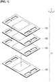
- FIG 1 is an exploded perspective view illustrating the fuel cell stack 10 in a metal support cell type solid oxide fuel cell.
- the fuel cell stack 10 is configured by stacking a plurality of cell units 100 in the vertical direction.
- the vertical direction of the fuel cell stack 10 represented by the z-axis in the drawings is also referred to as the "stacking direction.”
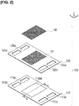
- FIG. 2 is an exploded perspective view of the cell unit 100.
- the cell unit 100 is configured by sequentially stacking a metal support cell assembly 110, a separator 120 provided with flow passage portions 121 that define flow passages F for gas, including anode gas and cathode gas, and an auxiliary collector layer 130.
- a contact material may be disposed between the metal support cell assembly 110 and the auxiliary collector layer 130 so as to bring the two into conductive contact, or the auxiliary collector layer 130 may be omitted.
- the cell unit 100 is composed of the metal support cell assembly 110 and the separator 120, and has an outer edge seal part 190 (refer to Figure 5 ) that seals the anode gas supplied to the electrolyte electrode assembly.
- the outer edge seal part 190 is formed of a material having heat resistance and sealing properties.
- An example of such a material is Thermiculite (registered trademark), the main material of which is vermiculite (vermiculite).
- a seal made of a glass component is also possible to use.
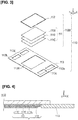
- Figure 3 is an exploded perspective view of the metal support cell assembly 110
- Figure 4 is a partial cross-sectional view thereof.
- the metal support cell assembly 110 has a metal support cell (MSC) 110M and a cell frame 113 that holds the outer circumference of the metal support cell 110M.
- MSC metal support cell
- the metal support cell 110M has an electrolyte electrode assembly 111 and a metal support part 112 that supports the electrolyte electrode assembly 111 from one side in the vertical direction.
- the metal support cell 110M has better mechanical strength and more rapid activating ability than electrolyte-supported cells and electrode-supported cells.
- the electrolyte electrode assembly 111 is formed by stacking, on both sides of an electrolyte layer 111E, a pair of electrodes, an anode layer 111A and a cathode layer 111C.
- the anode layer 111A is a fuel electrode, and reacts an anode gas (for example, hydrogen) with oxide ions to thereby generate an oxide of the anode gas and extract electrons.
- the anode layer 111A is resistant to a reducing atmosphere, allows the anode gas to pass therethrough, has high electrical (electron and ion) conductivity, and has a catalytic action to react the anode gas with the oxide ions.
- An example of a material forming the anode layer 111A is a material in which, for example, a metal such as nickel and an oxide ion conductor such as yttria-stabilized zirconia are mixed.
- the cathode layer 111C is an oxidant electrode, and reacts a cathode gas (for example, oxygen contained in air) with electrons to convert oxygen molecules to oxide ions.
- the cathode layer 111C is resistant to oxidizing atmosphere, allows the cathode gas to pass therethrough, has high electric (electron and ion) conductivity, and has a catalytic action to convert oxygen molecules into oxide ions.
- An example of a material forming the cathode layer 111C is an oxide of, for example, lanthanum, strontium, manganese, or cobalt.
- the electrolyte layer 111E allows oxide ions to pass from the cathode layer 111C to the anode layer 111A.
- the electrolyte layer 111E allows oxide ions to pass but does not allow gas and electrons to pass.
- An example of a material forming the electrolyte layer 111E is a solid oxide ceramic, such as stabilized zirconia in which yttria, neodymium oxide, samaria, gadria, scandia, and the like are doped.
- the metal support part 112 supports the electrolyte electrode assembly 111 from the anode layer 111A side. By supporting the electrolyte electrode assembly 111 with the metal support part 112, it is possible to suppress damage to the power generation cell 111 due to bending even if a slight bias in the surface pressure distribution occurs in the electrolyte electrode assembly 111.
- the metal support part 112 is a porous metal having gas permeability and electrical conductivity. Examples of a material forming the metal support part 112 include corrosion-resistant alloys containing nickel and chromium, corrosion-resistant steel, and stainless steel.
- the cell frame 113 holds the metal support cell 110M from the periphery.
- the cell frame 113 has an opening 113H.
- the metal support cell 110M is disposed in the opening 113H of the cell frame 113.
- the outer circumference of the metal support cell 110M is joined to the periphery of the opening 113H of the cell frame 113.
- An example of a material forming the cell frame 113 is a metal whose surface is subjected to an insulation treatment.
- the cell frame 113 has an anode gas inlet 113a and an anode gas outlet 113b through which the anode gas flows, and a cathode gas inlet 113c and a cathode gas outlet 113d through which the cathode gas flows.
- FIG. 5 is a cross-sectional view illustrating the main part of the fuel cell stack 10.
- the separator 120 has flow passage portions 121 in a region opposing the electrolyte electrode assembly 111 of the metal support cell 110M.
- the flow passage portions 121 have convex/concave shapes that define flow passages for gas, together with the power generation cell 111 therebetween.
- Anode gas AG flows in the flow passage portions 121 facing the metal support part 112, and cathode gas CG flows in the flow passage portions 121 facing the auxiliary collector layer 130.
- the flow passage portions 121 of the separator 120 are formed in an essentially linear shape such that the convex/concave shapes extend in the longitudinal direction Y.
- the direction of the flow of the gas that flows along the flow passage portions 121 is the longitudinal direction Y.
- an example of a material forming the separator 120 is a metal.
- the separator 120 has an anode gas inlet 125a and an anode gas outlet 125b through which the anode gas flows, and a cathode gas inlet 125c and a cathode gas outlet 125d through which the cathode gas flows.
- the auxiliary collector layer 130 is disposed between the metal support cell 110M and the separator 120, forms a space through which the cathode gas CG passes, equalizes the surface pressure, and assists the electrical contact between the metal support cell 110M and the separator 120.
- the auxiliary collector layer 130 is, for example, an expanded metal wire mesh.
- the auxiliary collector layer can be omitted if the characteristics and functions thereof can be achieved by another element.
- FIG. 6 is a schematic overview illustrating a fuel cell system.
- the illustrated fuel cell system 200 assumes an SOFC 210 mounted on an automobile.
- Raw fuel RF such as hydrogen and hydrocarbon is supplied to a reformer 225 via a fuel tank 221, a fuel pump 222, an evaporator 223, and a fuel gas heater 224.
- the reformer 225 generates hydrogen-rich reformed gas from the raw fuel RF by means of steam reforming.
- the reformed gas is hydrogen-containing gas HG, which is supplied to the fuel cell stack 10 of the SOFC 210 as the anode gas AG.
- Oxygen, or oxygen-containing gas OG such as air containing oxygen, is supplied to the fuel cell stack 10 as the cathode gas CG via a blower 31 and a heat exchanger 32.
- the exhaust gas of the cathode gas CG and the exhaust gas of the anode gas AG discharged from the fuel cell stack 10 are respectively supplied to an exhaust gas combustor 241.
- the exhaust gas burned in the exhaust gas combustor 241 is split into two flows.
- One exhaust gas 242 is discharged after sequentially undergoing heat exchange with the raw fuel RF in the reformer 225, the fuel gas heater 224, and the evaporator 223.
- the other exhaust gas 243 is discharged from a heat exchanger 232 after undergoing heat exchange with the oxygen-containing gas OG in the heat exchanger 232.
- the exhaust gas discharged from the evaporator 223 and the heat exchanger 232 are mixed and discharged.
- the electric power generated in the fuel cell stack 10 is voltage-controlled via an FC converter 251, a DCDC converter (14V) 252, and a DCDC converter (48V) 253 and supplied to an inverter 254.
- the inverter 254 converts the voltage-controlled DC power into AC power, and supplies the converted power to a travel driving motor 255.
- the DCDC converter (14V) 252 supplies DC power to auxiliary power consumption devices 256 such as accessories, pumps, and sensors mounted on the automobile.
- the fuel cell stack 10 is connected to an auxiliary power source 257, such as a secondary battery.
- the auxiliary power source 257 stores the electric power generated in the fuel cell stack 10 as well as collecting and storing braking energy of the automobile.
- the fuel cell system 200 has a control unit 260 for controlling the operation of the entire system.
- a voltmeter 261 for measuring an open circuit voltage (OCV) of the fuel cell stack 10 is connected to the fuel cell stack 10.
- the open circuit voltage is the voltage when a load, such as the motor 255, is not connected to the SOFC 210.
- a value of the open circuit voltage measured by the voltmeter 261 is input to the control unit 260.
- a temperature sensor 262 for measuring the temperature of the fuel cell stack 10 is connected to the fuel cell stack 10.
- a value of the temperature of the fuel cell stack 10 measured by the temperature sensor 262 is input to the control unit 260.
- a portion of the raw fuel RF can be supplied to the exhaust gas combustor 241 with the fuel pump 222.
- the temperature of the oxygen-containing gas OG supplied to the cathode layer 111C is adjusted by adjusting the amount of the raw fuel RF supplied to the exhaust gas combustor 241, the combustion temperature in the exhaust gas combustor 241, and the amount of high-temperature exhaust gas supplied from the exhaust gas combustor 241 to the heat exchanger 232.
- the temperature of the fuel cell stack 10 can be made higher than the normal operating temperature by increasing the temperature of the oxygen-containing gas OG supplied to the cathode layer 111C.
- the temperature of the fuel cell stack 10 is about 600°C to 650°C under normal operation. In the present embodiment, the temperature of the fuel cell stack 10 can be set to about 850°C.
- the SOFC 210 exhibits a gradual decrease in voltage when operated over a long period of time.
- the voltage drop of the SOFC 210 is known to be caused by a decrease in catalyst activity of the anode layer 111A.
- the power generation characteristics may be lower than what normally could be achieved before treatment after assembly of the stack.
- the present embodiment provides an anode layer activation method that makes sufficient use of the characteristic excellent mechanical strength of the metal support cell 110M. That is,
- the anode layer activation method in a solid oxide fuel cell according to the present embodiment is a method for activating the anode layer 111A in a solid oxide fuel cell having the metal support cell 110M, in which the nickel containing anode layer 111A, the electrolyte layer 111E, and the cathode layer 111C are stacked on the metal support part 112 made of metal.
- the oxygen-containing gas OG is introduced into the anode layer 111A to oxidize the nickel (Ni), after which the hydrogen-containing gas HG is introduced into the anode layer 111A to reduce the oxidized nickel (NiO).
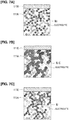
- Figure 7A is a schematic diagram illustrating the anode layer 111A before cell activation
- Figure 7B is a schematic diagram illustrating the anode layer 111A in a state in which the nickel is oxidized
- Figure 7C is a schematic diagram illustrating the anode layer 111A in a state in which the oxidized nickel is reduced.
- NiO nickel oxide
- the nickel oxide formed by oxidizing the nickel connects the originally unconnected network of nickel. Since the volume of nickel oxide is larger (expands) than nickel, nickel that were out of reach (not in contact) can be connected.
- Connects the originally unconnected network of nickel means not only when nickel that were not originally in contact with each other come into contact, but also cases in which the nickel that were in contact come in close contact such that the contact area increases. However, catalyst activity is low when still in the nickel oxide state.
- the nickel oxide formed by oxidizing the nickel has a larger volume (expands) than nickel. Since the metal support cell 110M has the characteristic of having excellent mechanical strength, cracks will not occur in the electrolyte layer 111E or in the anode layer 111A itself supported by the metal support part 112, even if such volume change occurs.
- Figure 8 is a diagram schematically illustrating the relationship between current and cell voltage, which represents the performance of the SOFC 210, wherein the broken line indicates the relationship between the current and the cell voltage before the anode layer 111A activation process, and the solid line indicates the relationship between the current and the cell voltage after the anode layer 111A activation process.
- the electrochemical reaction in the anode layer 111A is activated, and the performance of the SOFC 210 is improved.
- a solid oxide fuel cell system 200 that embodies the anode layer activation method described above comprises the SOFC 210 having the metal support cell 110M in which the nickel containing anode layer 111A, the electrolyte layer 111E, and the cathode layer 111C are stacked on the metal support part 112, the fuel introduction unit for introducing the hydrogen-containing gas HG into the anode layer 111A, the oxidation processing unit for introducing the oxygen-containing gas OG into the anode layer 111A, and the control unit 260 for controlling the operations of the fuel introduction unit and the oxidation processing unit.
- control unit 260 When activating the anode layer 111A, the control unit 260 operates the oxidation processing unit and introduces the oxygen-containing gas OG into the anode layer 111A to oxidize the nickel, and operates the fuel introduction unit and introduces the hydrogen-containing gas HG into the anode layer 111A to reduce the oxidized nickel.
- the SOFC 210 has a first valve 271 that switches between introduction of the hydrogen-containing gas HG into the anode layer 111A and stopping the introduction thereof.
- the SOFC 210 has a second valve 272 that switches between introduction of the oxygen-containing gas OG supplied to the cathode layer 111C into the anode layer 111A and stopping the introduction thereof.
- the hydrogen-containing gas HG is introduced into the anode layer 111A by opening the first valve 271 and closing the second valve 272. From this state, the introduction of the hydrogen-containing gas HG into the anode layer 111A is stopped by closing the first valve 271.
- the oxygen-containing gas OG is introduced into the anode layer 111A by closing the first valve 271 and opening the second valve 272. From this state, the introduction of the oxygen-containing gas OG into the anode layer 111A is stopped by closing the second valve 272.
- the constituent devices (221, 222, 223, 224, 225) from the fuel tank 221 to the fuel cell stack 10, the first valve 271, and the second valve 272 constitute the fuel introduction unit for introducing the hydrogen-containing gas HG into the anode layer 111A.
- the blower 231, the heat exchanger 232, the first valve 271, and the second valve 272 constitute the oxidation processing unit for introducing the oxygen-containing gas OG into the anode layer 111A.
- Figure 9 is a flow chart illustrating a procedure for executing the first embodiment of the anode layer 111A activation process.
- Figure 10 is a time chart illustrating the first embodiment of the anode layer 111A activation process.
- the horizontal axis is time.
- the vertical axis schematically represents the temperature of the fuel cell stack 10 (hereinafter sometimes simply referred to as "stack temperature Ts"), the flow rate Q (OG) of the oxygen-containing gas OG supplied to the anode layer 111A, and the flow rate Q (HG) of the hydrogen-containing gas HG supplied to the anode layer 111A.
- the temperature range indicated by the arrow with the reference symbol 281 is the temperature range in which the oxygen-containing gas OG and the hydrogen-containing gas HG are introduced, that is, the temperature range of a processing temperature Tp at which the oxidation/reduction of the nickel are carried out.
- the control unit 260 closes the first valve 271 and the second valve 272 (Step S11).
- the hydrogen-containing gas HG and the oxygen-containing gas OG have not been introduced into the anode layer 111A.
- An arbitrary determination criterion for determining whether or not to carry out the anode layer 111A activation process may be set, such as whether an integrated operating time of the SOFC 210 has become greater than or equal to a preset threshold, or whether the open circuit voltage measured by the voltmeter 261 has become less than or equal to a preset threshold.
- the control unit 260 determines whether or not the temperature of the fuel cell stack 10 measured by the temperature sensor 262 has reached the processing temperature Tp for carrying out activation (Step S12).
- the stack temperature Ts can be made higher than the normal operating temperature Td by increasing the temperature of the oxygen-containing gas OG supplied to the cathode layer 111C.
- the control unit 260 stands by until the stack temperature Ts reaches the processing temperature Tp (Step S12 "NO").
- the control unit 260 opens the second valve 272 of the oxidation processing unit to introduce the oxygen-containing gas OG into the anode layer 111A (Step S12 "YES,” Step S13).
- the length of time for introducing the oxygen-containing gas OG into the anode layer 111A is set in advance.
- the control unit 260 starts to count the elapsed time (Step S14).
- the control unit 260 opens the first valve 271 of the fuel introduction unit to introduce the hydrogen-containing gas HG into the anode layer 111A (Step S16).
- the length of time t (HG) for introducing the hydrogen-containing gas HG into the anode layer 111A is set in advance.
- the control unit 260 starts to count the elapsed time (Step S17).
- the hydrogen-containing gas HG is introduced into the anode layer 111A to reduce the oxidized nickel (NiO).
- the anode layer 111A is activated and the performance of the SOFC 210 is restored.
- the control unit 260 lowers the stack temperature Ts to the operating temperature Td, and operates the SOFC 210 normally (Step S18).
- the anode layer activation method in a solid oxide fuel cell is a method for activating the anode layer 111A in a solid oxide fuel cell having the metal support cell 110M.
- this anode layer activation method first, the oxygen-containing gas OG is introduced into the anode layer 111A to oxidize the nickel (Ni), after which the hydrogen-containing gas HG is introduced into the anode layer 111A to reduce the oxidized nickel (NiO).
- the solid oxide fuel cell system 200 according to the present embodiment that embodies the anode layer activation method described above comprises the SOFC 210 having the metal support cell 110M, the fuel introduction unit for introducing the hydrogen-containing gas HG into the anode layer 111A, the oxidation processing unit for introducing the oxygen-containing gas OG into the anode layer 111A, and the control unit 260 for controlling the operations of the fuel introduction unit and the oxidation processing unit.
- control unit 260 When activating the anode layer 111A, the control unit 260 operates the oxidation processing unit and introduces the oxygen-containing gas OG into the anode layer 111A to oxidize the nickel, and operates the fuel introduction unit and introduces the hydrogen-containing gas HG into the anode layer 111A to reduce the oxidized nickel.
- anode layer activation method and the solid oxide fuel cell system 200 configured in this manner, a relatively large number of conduction paths, which electrically connect the electrolyte layer 111E to the metal support part 112, are formed in the anode layer 111A, by oxidizing and reducing the nickel of the anode layer 111A.
- the three-phase boundary defined by the three phases of the nickel, an electrolyte, and pores increase.
- the electrochemical reaction in the anode layer 111A is activated, and the performance of the SOFC 210 is improved.
- the nickel oxide formed by oxidizing the nickel has a larger volume (expands) than nickel. Since the metal support cell 110M has the characteristic of having excellent mechanical strength, cracks will not occur in the electrolyte layer 111E or in the anode layer 111A itself supported by the metal support part 112, even if such volume change occurs.
- the oxygen-containing gas OG is normally used as the cathode gas CG and the hydrogen-containing gas HG is normally used as the anode gas AG in the SOFC 210, it is not necessary to assemble a dedicated device used only for the anode layer 111A activation process of the SOFC 210. Accordingly, it is possible to execute the anode layer 111A activation process and the performance improvement process of the SOFC 210 without adding an extra system. Moreover, since it is applied to the SOFC 210 mounted on an automobile, it is not necessary to execute the performance improvement process in another location, such as a dedicated factory for executing the activation process. The performance improvement process of the SOFC 210 can be executed using the simple fuel cell system 200 mounted on the automobile. Additionally, it is also possible to immediately execute the activation process when the performance improvement process of the SOFC 210 becomes necessary.
- the introduction of the oxygen-containing gas OG and the hydrogen-containing gas HG is preferably executed at the processing temperature Tp of 400°C to 850°C. If the temperatures of the oxygen-containing gas OG and the hydrogen-containing gas HG are less than 400°C, the oxidation reaction and the reduction reaction progress slowly, and the reaction time also becomes long. Additionally, if the temperatures of the oxygen-containing gas OG and the hydrogen-containing gas HG are increased, the reactions easily progress, and the processing time is also shortened. However, when the temperatures of the oxygen-containing gas OG and the hydrogen-containing gas HG exceed 850°C, the metal support part 112, the cell frame 113, and the like are oxidized, which could cause deterioration of the anode layer 111A.
- the introduction of the oxygen-containing gas OG and the hydrogen-containing gas HG is preferably executed at the processing temperature Tp of 400°C to 850°C.
- the introduction of the oxygen-containing gas OG and the hydrogen-containing gas HG is preferably executed at a processing temperature Tp that is higher than the operating temperature Td of the SOFC 210.
- the operating temperature Td is, for example, 600°C to 650°C; for example, the operating temperature Td is 650°C.
- the processing temperature Tp is, for example, 700°C.
- the introduction of the oxygen-containing gas OG and the hydrogen-containing gas HG is preferably executed at a processing temperature Tp that is higher than the operating temperature Td of the SOFC 210.
- the oxygen-containing gas OG is preferably air. Since air is normally used as the cathode gas CG in the SOFC 210, it is not necessary to assemble a dedicated device used only for the anode layer 111A activation process to the SOFC 210. Accordingly, it is possible to execute the anode layer 111A activation process and the performance improvement process of the SOFC 210 without adding an extra system. Moreover, since it is applied to the SOFC 210 mounted on an automobile, it is not necessary to execute the performance improvement process in another location, such as a dedicated factory for executing the activation process. The performance improvement process of the SOFC 210 can be executed using the simple fuel cell system 200 mounted on the automobile. Additionally, it is also possible to immediately execute the activation process when the performance improvement process of the SOFC 210 becomes necessary.
- the introduction times of the oxygen-containing gas OG and the hydrogen-containing gas HG are preferably set to 2 hours or more. It is thereby possible to sufficiently cause the oxidation/reduction reaction, and to obtain a sufficient activation effect of the anode layer 111A.
- the introduction time of 2 hours or more is the time at which the reaction is kinetically completed, and can be determined as follows. When measuring change in the mass of the anode layer 111A after the activation process is started, the mass increases as the nickel is oxidized in an oxidation process, so that the time at which the mass no longer increases could be regarded as the time at which the oxidation reaction is completed.
- the elapsed time until the oxidation reaction was completed was determined as the introduction time (2 hours) for the oxygen-containing gas OG. Since the mass decreases as the nickel oxide is reduced in a reduction process, the time at which the mass no longer decreases could be regarded as the time at which the reduction reaction is completed. Thus, the elapsed time until the reduction reaction was completed was determined as the introduction time (2 hours) for the hydrogen-containing gas HG.
- the respective potential of the anode layer 111A at the time of the oxidation process and the time of the reduction process is a natural potential.
- a pulse voltage is applied from an external power source to the anode layer 111A and/or the cathode layer 111C to carry out the anode layer 111A activation process.
- the anode layer 111A activation process is carried out without forcibly sweeping the potential. It is not necessary to assemble a dedicated device used only for the anode layer 111A activation process of the SOFC 210. Accordingly, it is possible to execute the anode layer 111A activation process and the performance improvement process of the SOFC 210 without adding an extra system.
- only one set of the oxidation process and the reduction process of the anode layer 111A is carried out per one switch to the introduction of the hydrogen-containing gas HG after the introduction of the oxygen-containing gas OG.
- the anode layer 111A activation process can be executed a plurality of times, if the oxidation and reduction set is repeated a plurality of times per one switch sintering of the nickel could occur, or the nickel grains could become large. If such a deterioration occurs, the effective catalytic reaction area necessary for the reaction of the anode layer 111A is lost.
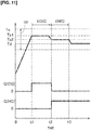
- Figure 11 is a time chart illustrating the second embodiment of the anode layer 111A activation process.
- the second embodiment of the anode layer 111A activation process is different from the first embodiment in the point that the introduction temperature of the hydrogen-containing gas HG is set to be lower than the introduction temperature of the oxygen-containing gas OG.
- the introduction temperature Tp1 of the oxygen-containing gas OG is, for example, 750°C
- the introduction temperature Tp2 of the hydrogen-containing gas HG is, for example, 700°C.
- the other points are the same as those in the first embodiment.
- the introduction temperature for the hydrogen-containing gas HG is preferably lower than the introduction temperature for the oxygen-containing gas OG. It is thereby possible to avoid undesired phenomena, such as sintering, while reducing the nickel oxide, even if the introduction temperature for the hydrogen-containing gas HG is reduced. Accordingly, in order to generate the necessary reduction reaction without deteriorating the anode layer 111A, the introduction temperature for the hydrogen-containing gas HG is preferably lower than the introduction temperature for the oxygen-containing gas OG.
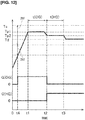
- Figure 12 is a time chart illustrating the third embodiment of the anode layer 111A activation process.
- the vertical axis schematically represents the stack temperature Ts, the flow rate Q (OG) of the oxygen-containing gas OG, and the flow rate Q (HG) of the hydrogen-containing gas HG.
- the temperature range indicated by the arrow with the reference symbol 281 is the temperature range of the processing temperature Tp at which the oxidation/reduction of the nickel are carried out.
- the temperature range indicated by the arrow with the reference symbol 282 is a firing temperature range of a binder contained in the constituent members of the SOFC 210.
- the third embodiment of the anode layer 111A activation process is different from the second embodiment in the point that the SOFC 210 includes a constituent member that contains a binder, and that the binder of the constituent member is burned and oxidized when oxidizing the nickel.
- the outer edge seal part 190 One example of a constituent member containing a binder is the outer edge seal part 190.
- the material forming the outer edge seal part 190 contains glass fiber as the main component instead of Thermiculite (registered trademark), and contains carbon as the binder.
- the temperature range of the processing temperature Tp for carrying out oxidation/reduction of the nickel, and the firing temperature range of the binder do not overlap.
- the second valve 272 of the oxidation processing unit opens to introduce the oxygen-containing gas OG into the anode layer 111A.
- the binder is burned and oxidized.
- the SOFC 210 preferably includes a constituent member that contains a binder, and the binder of the constituent member is burned and oxidized when oxidizing the nickel.
- the oxidation of the nickel and the firing (oxidation) of the binder are completed in a single process, when assembling the fuel cell stack 10.
- the outer edge seal part 190 is exemplified as the constituent member that contains the binder, the invention is not limited to this case.
- the binder component remains in another member, the oxidation of the nickel and the firing (oxidation) of the binder can be completed in a single process.
- Figure 13 is a time chart illustrating the fourth embodiment of the anode layer 111A activation process.
- the fourth embodiment of the anode layer 111A activation process is different from the third embodiment in the point that the temperature range of the processing temperature Tp for carrying out oxidation/reduction of the nickel, and the firing temperature range of the binder overlap.
- the second valve 272 of the oxidation processing unit opens to introduce the oxygen-containing gas OG into the anode layer 111A.
- the binder is burned and oxidized. Since the temperature range of the processing temperature Tp and the firing temperature range of the binder overlap, the oxidation of the nickel and the firing of the binder progress simultaneously.
- Figure 14 is a time chart illustrating the fifth embodiment of the anode layer 111A activation process.
- the vertical axis schematically represents the stack temperature Ts, the flow rate Q (OG) of the oxygen-containing gas OG, and the flow rate Q (HG) of the hydrogen-containing gas HG, and further schematically represent a flow rate Q (IG) of inert gas that is supplied to the anode layer 111A.
- the fifth embodiment of the anode layer 111A activation process is different from the first embodiment in the point that the introduced oxygen-containing gas OG is scavenged from the anode layer 111A before introducing the hydrogen-containing gas HG.
- the introduced oxygen-containing gas OG is scavenged from the anode layer 111A using inert gas.
- inert gas nitrogen gas can be used as the inert gas.
- the introduced oxygen-containing gas OG can be scavenged from the anode layer 111A by providing a system for opening the anode layer 111A to the atmosphere and a valve that is attached to the system.
- This configuration can be applied to the SOFC 210 mounted on an automobile.
- the inert gas is introduced into the anode layer 111A to scavenge the introduced oxygen-containing gas OG from the anode layer 111A.
- the first valve 271 of the fuel introduction unit opens to introduce the hydrogen-containing gas HG into the anode layer 111A (Step S16).
- the stack temperature Ts is lowered to the operating temperature Td, and the SOFC 210 is operated normally.
- a scavenging process between the introduction of the oxygen-containing gas OG and the introduction of the hydrogen-containing gas HG, it is possible to prevent the opportunity for the oxygen and the hydrogen to react directly, and to suppress reactions (heat generation) that are not necessary for the activation of the anode layer 111A. Accordingly, in order to safely and reliably cause the reactions necessary for activation, it is preferable to scavenge the introduced oxygen-containing gas OG from the anode layer 111A before introducing the hydrogen-containing gas HG.
- the oxygen-containing gas OG may be a gas containing oxygen obtained by means of a water dissociation reaction in a gas containing water. Even in cases in which air cannot be introduced into the anode layer 111A, the oxygen-containing gas OG can be introduced into the anode layer 111A by supplying the gas containing water.
- water in the gas containing water include water in a fuel gas containing water, such as ethanol mixed water, and water generated by means of a fuel cell reaction.
- the performance improvement process of the SOFC 210 can be executed using the simple fuel cell system 200 mounted on the automobile. Additionally, it is also possible to immediately execute the activation process when the performance improvement process of the SOFC 210 becomes necessary.
- the fuel cell system 200 shown in Figure 6 includes the second valve 272 in order to introduce, into the anode layer 111A, the oxygen-containing gas OG supplied to the cathode layer 111C.
- the configuration for introducing the oxygen-containing gas OG into the anode layer 111A is not limited to this configuration.
- exhaust gas can be used as the supply source of the oxygen-containing gas OG.
Landscapes
- Chemical & Material Sciences (AREA)
- Chemical Kinetics & Catalysis (AREA)
- Electrochemistry (AREA)
- General Chemical & Material Sciences (AREA)
- Engineering & Computer Science (AREA)
- Manufacturing & Machinery (AREA)
- Life Sciences & Earth Sciences (AREA)
- Sustainable Development (AREA)
- Sustainable Energy (AREA)
- Materials Engineering (AREA)
- Fuel Cell (AREA)
- Inert Electrodes (AREA)
Abstract
Description
- The present invention relates to a method for activating an anode layer in a solid oxide fuel cell, and a solid oxide fuel cell system.
- Solid oxide fuel cells (SOFC), (hereinafter sometimes simply referred to as "SOFC") have high thermal efficiency, are capable of electrochemically reacting fuel and air without using a noble metal catalyst, and can use numerous types of fuels. Although SOFC have such advantages, power generation performance is low at the start of power generation and a 100% characteristic cannot be exhibited; or, if operated over a long period of time under a constant load current a gradual decrease in voltage is exhibited. The voltage drop of SOFC is known to be caused by a decrease in catalyst activity of an anode layer.
- An electrode activation method for an SOFC disclosed in
Patent Document 1 is known as an electrode activation method that activates the anode layer in the SOFC. According to this electrode activation method, when output voltage decreases, first, the anode layer is placed in an inert gas atmosphere and the cathode layer is placed in an oxygen gas-containing atmosphere. A pulse voltage is then applied between the anode layer and the cathode layer. - Patent Document 1: Japanese Laid-Open Patent Application No.
2013-206684 - SOFCs include metal support cell type SOFCs, which have a structure in which a power generation cell (stacked anode layer, electrolyte layer, and cathode layer body) is supported by a metal support part. The metal support part is formed of a porous metal having gas permeability and electrical conductivity. A metal support cell has better mechanical strength than electrolyte-supported cells and electrode-supported cells. As a result, it is possible to thin the electrolyte layer and reduce electric resistance, to thereby improve power generation efficiency.
- The electrode activation method disclosed in
Patent Document 1 can be applied to a metal support cell type SOFC, but does not make sufficient use of the characteristic excellent mechanical strength of metal support cells. - An object of the present invention is to provide an anode layer activation method suitable for application to a metal support cell type solid oxide fuel cell, and a solid oxide fuel cell system.
- A method for activating an anode layer in a solid oxide fuel cell according to the present invention, which achieves the object described above, is an anode layer activation method in a solid oxide fuel cell having a metal support cell in which an anode layer containing nickel, an electrolyte layer and a cathode layer are stacked on a metal support part. In the anode layer activation method, first, an oxygen-containing gas is introduced into the anode layer to oxidize the nickel. Next, a hydrogen-containing gas is introduced into the anode layer to reduce the oxidized nickel.
- A solid oxide fuel cell system according to the present invention, which achieves the object described above, includes a solid oxide fuel cell having a metal support cell, in which an anode layer containing nickel, an electrolyte layer and a cathode layer are stacked on a metal support part. The solid oxide fuel cell system further includes a fuel introduction unit that introduces a hydrogen-containing gas into the anode layer, an oxidation processing unit that introduces an oxygen-containing gas into the anode layer, and a control unit that controls the operations of the fuel introduction unit and the oxidation processing unit. When activating the anode layer, the control unit is configured to operate the oxidation processing unit to introduce an oxygen-containing gas into the anode layer to oxidize the nickel, and unit is configured to operate the fuel introduction unit to introduce a hydrogen-containing gas into the anode layer to reduce the oxidized nickel.
- According to the present invention, it is possible to make sufficient use of the characteristic of metal support cells to thereby activate the anode layer.
-
-
Figure 1 is an exploded perspective view illustrating a fuel cell stack in a metal support cell type solid oxide fuel cell. -
Figure 2 is an exploded perspective view of a cell unit shown inFigure 1 . -
Figure 3 is an exploded perspective view of a metal support cell assembly shown inFigure 2 . -
Figure 4 is a partial cross-sectional view of the metal support cell assembly along line 4-4 inFigure 2 . -
Figure 5 is a cross-sectional view illustrating the main part of a fuel cell stack. -
Figure 6 is a schematic overview illustrating a fuel cell system. -
Figure 7A is a diagram schematically illustrating an anode layer in a state before cell activation. -
Figure 7B is a diagram schematically illustrating the anode layer in a state in which nickel is oxidized. -
Figure 7C is a diagram schematically illustrating the anode layer in a state in which the oxidized nickel is reduced. -
Figure 8 is diagram schematically illustrating the relationship between current and cell voltage, which represents the performance of a solid oxide fuel cell. -
Figure 9 is a flow chart illustrating a procedure for executing a first embodiment of an anode layer activation process. -
Figure 10 is a time chart illustrating the first embodiment of the anode layer activation process. -
Figure 11 is a time chart illustrating a second embodiment of the anode layer activation process. -
Figure 12 is a time chart illustrating a third embodiment of the anode layer activation process. -
Figure 13 is a time chart illustrating a fourth embodiment of the anode layer activation process. -
Figure 14 is a time chart illustrating a fifth embodiment of the anode layer activation process. - Embodiments of the present invention will be explained below, with reference to the appended drawings. The description below does not limit the technical scope, or the meanings of the terms described in the Claims. Dimensional ratios in the drawings are exaggerated for the sake of convenience of explanation and may differ from actual ratios.
- A
fuel cell stack 10 in a metal support cell type solid oxide fuel cell will be described with reference toFigures 1 to 5 . Thefuel cell stack 10 according to the present embodiment uses, as an electrolyte, a solid oxide fuel cell (SOFC), which uses an oxide ion conductor such as stabilized zirconia. - For the sake of convenience of the explanation below, an XYZ orthogonal coordinate system is shown is the drawings. The x-axis and the y-axis represent axes that are parallel with the horizontal direction, and the z-axis represents an axis that is parallel with the vertical direction.
-
Figure 1 is an exploded perspective view illustrating thefuel cell stack 10 in a metal support cell type solid oxide fuel cell. As shown inFigure 1 , thefuel cell stack 10 is configured by stacking a plurality ofcell units 100 in the vertical direction. The vertical direction of thefuel cell stack 10 represented by the z-axis in the drawings is also referred to as the "stacking direction." -
Figure 2 is an exploded perspective view of thecell unit 100. As shown inFigure 2 , thecell unit 100 is configured by sequentially stacking a metalsupport cell assembly 110, aseparator 120 provided withflow passage portions 121 that define flow passages F for gas, including anode gas and cathode gas, and anauxiliary collector layer 130. A contact material may be disposed between the metalsupport cell assembly 110 and theauxiliary collector layer 130 so as to bring the two into conductive contact, or theauxiliary collector layer 130 may be omitted. - The
cell unit 100 is composed of the metalsupport cell assembly 110 and theseparator 120, and has an outer edge seal part 190 (refer toFigure 5 ) that seals the anode gas supplied to the electrolyte electrode assembly. The outeredge seal part 190 is formed of a material having heat resistance and sealing properties. An example of such a material is Thermiculite (registered trademark), the main material of which is vermiculite (vermiculite). Alternatively, it is also possible to use a seal made of a glass component. -
Figure 3 is an exploded perspective view of the metalsupport cell assembly 110, andFigure 4 is a partial cross-sectional view thereof. As shown inFigures 3 and 4 , the metalsupport cell assembly 110 has a metal support cell (MSC) 110M and acell frame 113 that holds the outer circumference of themetal support cell 110M. - As shown in
Figures 3 and 4 , themetal support cell 110M has anelectrolyte electrode assembly 111 and ametal support part 112 that supports theelectrolyte electrode assembly 111 from one side in the vertical direction. Themetal support cell 110M has better mechanical strength and more rapid activating ability than electrolyte-supported cells and electrode-supported cells. - As shown in
Figures 3 and 4 , theelectrolyte electrode assembly 111 is formed by stacking, on both sides of anelectrolyte layer 111E, a pair of electrodes, ananode layer 111A and acathode layer 111C. - The
anode layer 111A is a fuel electrode, and reacts an anode gas (for example, hydrogen) with oxide ions to thereby generate an oxide of the anode gas and extract electrons. Theanode layer 111A is resistant to a reducing atmosphere, allows the anode gas to pass therethrough, has high electrical (electron and ion) conductivity, and has a catalytic action to react the anode gas with the oxide ions. An example of a material forming theanode layer 111A is a material in which, for example, a metal such as nickel and an oxide ion conductor such as yttria-stabilized zirconia are mixed. - The
cathode layer 111C is an oxidant electrode, and reacts a cathode gas (for example, oxygen contained in air) with electrons to convert oxygen molecules to oxide ions. Thecathode layer 111C is resistant to oxidizing atmosphere, allows the cathode gas to pass therethrough, has high electric (electron and ion) conductivity, and has a catalytic action to convert oxygen molecules into oxide ions. An example of a material forming thecathode layer 111C is an oxide of, for example, lanthanum, strontium, manganese, or cobalt. - The
electrolyte layer 111E allows oxide ions to pass from thecathode layer 111C to theanode layer 111A. Theelectrolyte layer 111E allows oxide ions to pass but does not allow gas and electrons to pass. An example of a material forming theelectrolyte layer 111E is a solid oxide ceramic, such as stabilized zirconia in which yttria, neodymium oxide, samaria, gadria, scandia, and the like are doped. - As shown in
Figures 3 and 4 , themetal support part 112 supports theelectrolyte electrode assembly 111 from theanode layer 111A side. By supporting theelectrolyte electrode assembly 111 with themetal support part 112, it is possible to suppress damage to thepower generation cell 111 due to bending even if a slight bias in the surface pressure distribution occurs in theelectrolyte electrode assembly 111. Themetal support part 112 is a porous metal having gas permeability and electrical conductivity. Examples of a material forming themetal support part 112 include corrosion-resistant alloys containing nickel and chromium, corrosion-resistant steel, and stainless steel. - As shown in
Figures 3 and 4 , thecell frame 113 holds themetal support cell 110M from the periphery. As shown inFigure 3 , thecell frame 113 has anopening 113H. Themetal support cell 110M is disposed in theopening 113H of thecell frame 113. The outer circumference of themetal support cell 110M is joined to the periphery of theopening 113H of thecell frame 113. An example of a material forming thecell frame 113 is a metal whose surface is subjected to an insulation treatment. - As shown in
Figure 3 , thecell frame 113 has ananode gas inlet 113a and ananode gas outlet 113b through which the anode gas flows, and acathode gas inlet 113c and acathode gas outlet 113d through which the cathode gas flows. -
Figure 5 is a cross-sectional view illustrating the main part of thefuel cell stack 10. As shown inFigure 5 , theseparator 120 hasflow passage portions 121 in a region opposing theelectrolyte electrode assembly 111 of themetal support cell 110M. Theflow passage portions 121 have convex/concave shapes that define flow passages for gas, together with thepower generation cell 111 therebetween. Anode gas AG flows in theflow passage portions 121 facing themetal support part 112, and cathode gas CG flows in theflow passage portions 121 facing theauxiliary collector layer 130. - As shown in
Figure 2 , theflow passage portions 121 of theseparator 120 are formed in an essentially linear shape such that the convex/concave shapes extend in the longitudinal direction Y. As a result, the direction of the flow of the gas that flows along theflow passage portions 121 is the longitudinal direction Y. While not particularly limited, an example of a material forming theseparator 120 is a metal. - As shown in
Figure 2 , theseparator 120 has ananode gas inlet 125a and ananode gas outlet 125b through which the anode gas flows, and acathode gas inlet 125c and acathode gas outlet 125d through which the cathode gas flows. - As shown in
Figure 5 , theauxiliary collector layer 130 is disposed between themetal support cell 110M and theseparator 120, forms a space through which the cathode gas CG passes, equalizes the surface pressure, and assists the electrical contact between themetal support cell 110M and theseparator 120. Theauxiliary collector layer 130 is, for example, an expanded metal wire mesh. The auxiliary collector layer can be omitted if the characteristics and functions thereof can be achieved by another element. - Next, the
fuel cell system 200 including a solidoxide fuel cell 210 will be described with reference toFigure 6 . -
Figure 6 is a schematic overview illustrating a fuel cell system. The illustratedfuel cell system 200 assumes anSOFC 210 mounted on an automobile. Raw fuel RF such as hydrogen and hydrocarbon is supplied to areformer 225 via a fuel tank 221, afuel pump 222, anevaporator 223, and afuel gas heater 224. Thereformer 225 generates hydrogen-rich reformed gas from the raw fuel RF by means of steam reforming. The reformed gas is hydrogen-containing gas HG, which is supplied to thefuel cell stack 10 of theSOFC 210 as the anode gas AG. Oxygen, or oxygen-containing gas OG such as air containing oxygen, is supplied to thefuel cell stack 10 as the cathode gas CG via a blower 31 and a heat exchanger 32. The exhaust gas of the cathode gas CG and the exhaust gas of the anode gas AG discharged from thefuel cell stack 10 are respectively supplied to anexhaust gas combustor 241. The exhaust gas burned in theexhaust gas combustor 241 is split into two flows. Oneexhaust gas 242 is discharged after sequentially undergoing heat exchange with the raw fuel RF in thereformer 225, thefuel gas heater 224, and theevaporator 223. Theother exhaust gas 243 is discharged from aheat exchanger 232 after undergoing heat exchange with the oxygen-containing gas OG in theheat exchanger 232. The exhaust gas discharged from theevaporator 223 and theheat exchanger 232 are mixed and discharged. - The electric power generated in the
fuel cell stack 10 is voltage-controlled via anFC converter 251, a DCDC converter (14V) 252, and a DCDC converter (48V) 253 and supplied to aninverter 254. Theinverter 254 converts the voltage-controlled DC power into AC power, and supplies the converted power to atravel driving motor 255. The DCDC converter (14V) 252 supplies DC power to auxiliarypower consumption devices 256 such as accessories, pumps, and sensors mounted on the automobile. Thefuel cell stack 10 is connected to anauxiliary power source 257, such as a secondary battery. Theauxiliary power source 257 stores the electric power generated in thefuel cell stack 10 as well as collecting and storing braking energy of the automobile. - The
fuel cell system 200 has acontrol unit 260 for controlling the operation of the entire system. Avoltmeter 261 for measuring an open circuit voltage (OCV) of thefuel cell stack 10 is connected to thefuel cell stack 10. The open circuit voltage is the voltage when a load, such as themotor 255, is not connected to theSOFC 210. A value of the open circuit voltage measured by thevoltmeter 261 is input to thecontrol unit 260. Atemperature sensor 262 for measuring the temperature of thefuel cell stack 10 is connected to thefuel cell stack 10. A value of the temperature of thefuel cell stack 10 measured by thetemperature sensor 262 is input to thecontrol unit 260. - A portion of the raw fuel RF can be supplied to the
exhaust gas combustor 241 with thefuel pump 222. The temperature of the oxygen-containing gas OG supplied to thecathode layer 111C is adjusted by adjusting the amount of the raw fuel RF supplied to theexhaust gas combustor 241, the combustion temperature in theexhaust gas combustor 241, and the amount of high-temperature exhaust gas supplied from theexhaust gas combustor 241 to theheat exchanger 232. - The temperature of the
fuel cell stack 10 can be made higher than the normal operating temperature by increasing the temperature of the oxygen-containing gas OG supplied to thecathode layer 111C. The temperature of thefuel cell stack 10 is about 600°C to 650°C under normal operation. In the present embodiment, the temperature of thefuel cell stack 10 can be set to about 850°C. - Activation of the
anode layer 111A in theSOFC 210 will be described next. - As described above, the
SOFC 210 exhibits a gradual decrease in voltage when operated over a long period of time. The voltage drop of theSOFC 210 is known to be caused by a decrease in catalyst activity of theanode layer 111A. Alternatively, the power generation characteristics may be lower than what normally could be achieved before treatment after assembly of the stack. - The present embodiment provides an anode layer activation method that makes sufficient use of the characteristic excellent mechanical strength of the
metal support cell 110M. That is, The anode layer activation method in a solid oxide fuel cell according to the present embodiment is a method for activating theanode layer 111A in a solid oxide fuel cell having themetal support cell 110M, in which the nickel containinganode layer 111A, theelectrolyte layer 111E, and thecathode layer 111C are stacked on themetal support part 112 made of metal. In this anode layer activation method, first, the oxygen-containing gas OG is introduced into theanode layer 111A to oxidize the nickel (Ni), after which the hydrogen-containing gas HG is introduced into theanode layer 111A to reduce the oxidized nickel (NiO). - Activation of the
anode layer 111A by means of oxidation and reduction will be described with reference toFigures 7A, 7B, and 7C. Figure 7A is a schematic diagram illustrating theanode layer 111A before cell activation,Figure 7B is a schematic diagram illustrating theanode layer 111A in a state in which the nickel is oxidized, andFigure 7C is a schematic diagram illustrating theanode layer 111A in a state in which the oxidized nickel is reduced. - As shown in
Figure 7A , before cell activation, there are relatively many locations in theanode layer 111A where adjacent nickel are not connected to each other but are rather separated. As a result, there are relatively few conduction paths that electrically connect theelectrolyte layer 111E to themetal support part 112 in theanode layer 111A. - As shown in
Figure 7B , when the oxygen-containing gas OG is introduced into theanode layer 111A to oxidize the nickel, as a result of the oxidation reaction
2Ni + O2 → 2NiO
nickel oxide (NiO) is formed. The nickel oxide formed by oxidizing the nickel connects the originally unconnected network of nickel. Since the volume of nickel oxide is larger (expands) than nickel, nickel that were out of reach (not in contact) can be connected. "Connects the originally unconnected network of nickel" means not only when nickel that were not originally in contact with each other come into contact, but also cases in which the nickel that were in contact come in close contact such that the contact area increases. However, catalyst activity is low when still in the nickel oxide state. - The nickel oxide formed by oxidizing the nickel has a larger volume (expands) than nickel. Since the
metal support cell 110M has the characteristic of having excellent mechanical strength, cracks will not occur in theelectrolyte layer 111E or in theanode layer 111A itself supported by themetal support part 112, even if such volume change occurs. - As shown in
Figure 7C , by introducing the hydrogen-containing gas HG into theanode layer 111A, the oxidized nickel is reduced while maintaining the connected nickel network, so that a relatively large number of conduction paths are formed. Although the volume decreases when the nickel oxide is returned to nickel, it is thought that the volume shrinks while maintaining the connection, rather than shrinkage being due to severed oxide connections. In addition to the formation of the conduction paths, a three-phase boundary (Three-Phase Boundary: TPB) defined by the three phases of the nickel, an electrolyte, and pores is increased compared to the state before cell activation (Figure 7A ). As a result of the nickel oxide being reduced to nickel, the catalyst activity becomes higher than that of NiO. -
Figure 8 is a diagram schematically illustrating the relationship between current and cell voltage, which represents the performance of theSOFC 210, wherein the broken line indicates the relationship between the current and the cell voltage before theanode layer 111A activation process, and the solid line indicates the relationship between the current and the cell voltage after theanode layer 111A activation process. According to theanode layer 111A activation method of the present embodiment, the electrochemical reaction in theanode layer 111A is activated, and the performance of theSOFC 210 is improved. - Conventionally, it has always been the case that the oxygen-containing gas OG is not introduced into the
anode layer 111A. This is because, as a result of the volume of the nickel or theentire anode layer 111A expanding when nickel is oxidized to nickel oxide, there is the risk that cracks occur in theelectrolyte layer 111E or theanode layer 111A itself, leading to destruction of thepower generation cell 111. - As a result of intensive research into a novel anode layer activation method, focusing on the characteristic excellent mechanical strength of the
metal support cell 110M, the present inventors broke through the conventional stereotype of not introducing the oxygen-containing gas OG into theanode layer 111A, and devised the above-described method for activating an anode layer in a solid oxide fuel cell. - A solid oxide
fuel cell system 200 according to the present embodiment that embodies the anode layer activation method described above comprises theSOFC 210 having themetal support cell 110M in which the nickel containinganode layer 111A, theelectrolyte layer 111E, and thecathode layer 111C are stacked on themetal support part 112, the fuel introduction unit for introducing the hydrogen-containing gas HG into theanode layer 111A, the oxidation processing unit for introducing the oxygen-containing gas OG into theanode layer 111A, and thecontrol unit 260 for controlling the operations of the fuel introduction unit and the oxidation processing unit. When activating theanode layer 111A, thecontrol unit 260 operates the oxidation processing unit and introduces the oxygen-containing gas OG into theanode layer 111A to oxidize the nickel, and operates the fuel introduction unit and introduces the hydrogen-containing gas HG into theanode layer 111A to reduce the oxidized nickel. - As shown in
Figure 6 , theSOFC 210 has afirst valve 271 that switches between introduction of the hydrogen-containing gas HG into theanode layer 111A and stopping the introduction thereof. TheSOFC 210 has asecond valve 272 that switches between introduction of the oxygen-containing gas OG supplied to thecathode layer 111C into theanode layer 111A and stopping the introduction thereof. The hydrogen-containing gas HG is introduced into theanode layer 111A by opening thefirst valve 271 and closing thesecond valve 272. From this state, the introduction of the hydrogen-containing gas HG into theanode layer 111A is stopped by closing thefirst valve 271. The oxygen-containing gas OG is introduced into theanode layer 111A by closing thefirst valve 271 and opening thesecond valve 272. From this state, the introduction of the oxygen-containing gas OG into theanode layer 111A is stopped by closing thesecond valve 272. - In the
fuel cell system 200 of the illustrated example, the constituent devices (221, 222, 223, 224, 225) from the fuel tank 221 to thefuel cell stack 10, thefirst valve 271, and thesecond valve 272 constitute the fuel introduction unit for introducing the hydrogen-containing gas HG into theanode layer 111A. In addition, the blower 231, theheat exchanger 232, thefirst valve 271, and thesecond valve 272 constitute the oxidation processing unit for introducing the oxygen-containing gas OG into theanode layer 111A. - The first embodiment of the
anode layer 111A activation process will be described next. -
Figure 9 is a flow chart illustrating a procedure for executing the first embodiment of theanode layer 111A activation process.Figure 10 is a time chart illustrating the first embodiment of theanode layer 111A activation process. In the time chart ofFigure 10 , the horizontal axis is time. The vertical axis schematically represents the temperature of the fuel cell stack 10 (hereinafter sometimes simply referred to as "stack temperature Ts"), the flow rate Q (OG) of the oxygen-containing gas OG supplied to theanode layer 111A, and the flow rate Q (HG) of the hydrogen-containing gas HG supplied to theanode layer 111A. The temperature range indicated by the arrow with thereference symbol 281 is the temperature range in which the oxygen-containing gas OG and the hydrogen-containing gas HG are introduced, that is, the temperature range of a processing temperature Tp at which the oxidation/reduction of the nickel are carried out. - As shown in
Figure 9 , when theanode layer 111A activation process is started (t = 0 inFigure 10 ), thecontrol unit 260 closes thefirst valve 271 and the second valve 272 (Step S11). The hydrogen-containing gas HG and the oxygen-containing gas OG have not been introduced into theanode layer 111A. An arbitrary determination criterion for determining whether or not to carry out theanode layer 111A activation process may be set, such as whether an integrated operating time of theSOFC 210 has become greater than or equal to a preset threshold, or whether the open circuit voltage measured by thevoltmeter 261 has become less than or equal to a preset threshold. - The
control unit 260 determines whether or not the temperature of thefuel cell stack 10 measured by thetemperature sensor 262 has reached the processing temperature Tp for carrying out activation (Step S12). The stack temperature Ts can be made higher than the normal operating temperature Td by increasing the temperature of the oxygen-containing gas OG supplied to thecathode layer 111C. Thecontrol unit 260 stands by until the stack temperature Ts reaches the processing temperature Tp (Step S12 "NO"). - When the stack temperature Ts reaches the processing temperature Tp (t = t1 in
Figure 10 ), thecontrol unit 260 opens thesecond valve 272 of the oxidation processing unit to introduce the oxygen-containing gas OG into theanode layer 111A (Step S12 "YES," Step S13). The length of time for introducing the oxygen-containing gas OG into theanode layer 111A is set in advance. When opening thesecond valve 272, thecontrol unit 260 starts to count the elapsed time (Step S14). - When the oxygen-containing gas OG is introduced into the
anode layer 111A to oxidize the nickel, as a result of the oxidation reaction
2Ni + O2 → 2NiO
nickel oxide is formed. - When time t (OG) for introducing the oxygen-containing gas OG elapses (t = t2 in
Figure 10 ), thecontrol unit 260 closes thesecond valve 272 of the oxidation processing unit to stop the introduction of the oxygen-containing gas OG into theanode layer 111A (Step S14 "YES," Step S15). - The
control unit 260 opens thefirst valve 271 of the fuel introduction unit to introduce the hydrogen-containing gas HG into theanode layer 111A (Step S16). The length of time t (HG) for introducing the hydrogen-containing gas HG into theanode layer 111A is set in advance. When opening thefirst valve 271, thecontrol unit 260 starts to count the elapsed time (Step S17). - The hydrogen-containing gas HG is introduced into the
anode layer 111A to reduce the oxidized nickel (NiO). - By means of such oxidation and reduction of the
anode layer 111A, theanode layer 111A is activated and the performance of theSOFC 210 is restored. - When the time t (HG) for introducing the hydrogen-containing gas HG elapses (t = t3 in
Figure 10 ), thecontrol unit 260 lowers the stack temperature Ts to the operating temperature Td, and operates theSOFC 210 normally (Step S18). - As described above, The anode layer activation method in a solid oxide fuel cell according to the present embodiment is a method for activating the
anode layer 111A in a solid oxide fuel cell having themetal support cell 110M. In this anode layer activation method, first, the oxygen-containing gas OG is introduced into theanode layer 111A to oxidize the nickel (Ni), after which the hydrogen-containing gas HG is introduced into theanode layer 111A to reduce the oxidized nickel (NiO). - In addition, the solid oxide
fuel cell system 200 according to the present embodiment that embodies the anode layer activation method described above comprises theSOFC 210 having themetal support cell 110M, the fuel introduction unit for introducing the hydrogen-containing gas HG into theanode layer 111A, the oxidation processing unit for introducing the oxygen-containing gas OG into theanode layer 111A, and thecontrol unit 260 for controlling the operations of the fuel introduction unit and the oxidation processing unit. When activating theanode layer 111A, thecontrol unit 260 operates the oxidation processing unit and introduces the oxygen-containing gas OG into theanode layer 111A to oxidize the nickel, and operates the fuel introduction unit and introduces the hydrogen-containing gas HG into theanode layer 111A to reduce the oxidized nickel. - According to the anode layer activation method and the solid oxide
fuel cell system 200 configured in this manner, a relatively large number of conduction paths, which electrically connect theelectrolyte layer 111E to themetal support part 112, are formed in theanode layer 111A, by oxidizing and reducing the nickel of theanode layer 111A. In addition, the three-phase boundary defined by the three phases of the nickel, an electrolyte, and pores increase. As a result, the electrochemical reaction in theanode layer 111A is activated, and the performance of theSOFC 210 is improved. - The nickel oxide formed by oxidizing the nickel has a larger volume (expands) than nickel. Since the
metal support cell 110M has the characteristic of having excellent mechanical strength, cracks will not occur in theelectrolyte layer 111E or in theanode layer 111A itself supported by themetal support part 112, even if such volume change occurs. - In addition, since the oxygen-containing gas OG is normally used as the cathode gas CG and the hydrogen-containing gas HG is normally used as the anode gas AG in the
SOFC 210, it is not necessary to assemble a dedicated device used only for theanode layer 111A activation process of theSOFC 210. Accordingly, it is possible to execute theanode layer 111A activation process and the performance improvement process of theSOFC 210 without adding an extra system. Moreover, since it is applied to theSOFC 210 mounted on an automobile, it is not necessary to execute the performance improvement process in another location, such as a dedicated factory for executing the activation process. The performance improvement process of theSOFC 210 can be executed using the simplefuel cell system 200 mounted on the automobile. Additionally, it is also possible to immediately execute the activation process when the performance improvement process of theSOFC 210 becomes necessary. - The introduction of the oxygen-containing gas OG and the hydrogen-containing gas HG is preferably executed at the processing temperature Tp of 400°C to 850°C. If the temperatures of the oxygen-containing gas OG and the hydrogen-containing gas HG are less than 400°C, the oxidation reaction and the reduction reaction progress slowly, and the reaction time also becomes long. Additionally, if the temperatures of the oxygen-containing gas OG and the hydrogen-containing gas HG are increased, the reactions easily progress, and the processing time is also shortened. However, when the temperatures of the oxygen-containing gas OG and the hydrogen-containing gas HG exceed 850°C, the
metal support part 112, thecell frame 113, and the like are oxidized, which could cause deterioration of theanode layer 111A. Accordingly, in order to generate the necessary oxidation/reduction reaction without deteriorating theanode layer 111A, the introduction of the oxygen-containing gas OG and the hydrogen-containing gas HG is preferably executed at the processing temperature Tp of 400°C to 850°C. - The introduction of the oxygen-containing gas OG and the hydrogen-containing gas HG is preferably executed at a processing temperature Tp that is higher than the operating temperature Td of the
SOFC 210. The operating temperature Td is, for example, 600°C to 650°C; for example, the operating temperature Td is 650°C. In the case of this operating temperature Td, the processing temperature Tp is, for example, 700°C. Although it is not preferable to operate theSOFC 210 for a long period of time at a temperature higher than the normal operating temperature Td, the cell is not deteriorated even if the stack temperature Ts is raised to a temperature higher than the normal operating temperature Td, if only for a relatively short period of time to carry out theanode layer 111A activation process. Additionally, since the temperatures of the oxygen-containing gas OG and the hydrogen-containing gas HG are increased, the reactions easily progress, and the processing time can be shortened. Accordingly, in order to promote the necessary oxidation/reduction reaction without deteriorating theanode layer 111A, the introduction of the oxygen-containing gas OG and the hydrogen-containing gas HG is preferably executed at a processing temperature Tp that is higher than the operating temperature Td of theSOFC 210. - The oxygen-containing gas OG is preferably air. Since air is normally used as the cathode gas CG in the
SOFC 210, it is not necessary to assemble a dedicated device used only for theanode layer 111A activation process to theSOFC 210. Accordingly, it is possible to execute theanode layer 111A activation process and the performance improvement process of theSOFC 210 without adding an extra system. Moreover, since it is applied to theSOFC 210 mounted on an automobile, it is not necessary to execute the performance improvement process in another location, such as a dedicated factory for executing the activation process. The performance improvement process of theSOFC 210 can be executed using the simplefuel cell system 200 mounted on the automobile. Additionally, it is also possible to immediately execute the activation process when the performance improvement process of theSOFC 210 becomes necessary. - The introduction times of the oxygen-containing gas OG and the hydrogen-containing gas HG are preferably set to 2 hours or more. It is thereby possible to sufficiently cause the oxidation/reduction reaction, and to obtain a sufficient activation effect of the
anode layer 111A. Here, the introduction time of 2 hours or more is the time at which the reaction is kinetically completed, and can be determined as follows. When measuring change in the mass of theanode layer 111A after the activation process is started, the mass increases as the nickel is oxidized in an oxidation process, so that the time at which the mass no longer increases could be regarded as the time at which the oxidation reaction is completed. Thus, the elapsed time until the oxidation reaction was completed was determined as the introduction time (2 hours) for the oxygen-containing gas OG. Since the mass decreases as the nickel oxide is reduced in a reduction process, the time at which the mass no longer decreases could be regarded as the time at which the reduction reaction is completed. Thus, the elapsed time until the reduction reaction was completed was determined as the introduction time (2 hours) for the hydrogen-containing gas HG. - The respective potential of the
anode layer 111A at the time of the oxidation process and the time of the reduction process is a natural potential. In the technique disclosed inPatent Document 1, a pulse voltage is applied from an external power source to theanode layer 111A and/or thecathode layer 111C to carry out theanode layer 111A activation process. In contrast, in the present embodiment, theanode layer 111A activation process is carried out without forcibly sweeping the potential. It is not necessary to assemble a dedicated device used only for theanode layer 111A activation process of theSOFC 210. Accordingly, it is possible to execute theanode layer 111A activation process and the performance improvement process of theSOFC 210 without adding an extra system. Preferably, only one set of the oxidation process and the reduction process of theanode layer 111A is carried out per one switch to the introduction of the hydrogen-containing gas HG after the introduction of the oxygen-containing gas OG. Although theanode layer 111A activation process can be executed a plurality of times, if the oxidation and reduction set is repeated a plurality of times per one switch sintering of the nickel could occur, or the nickel grains could become large. If such a deterioration occurs, the effective catalytic reaction area necessary for the reaction of theanode layer 111A is lost. Accordingly, in order to prevent the deterioration of theanode layer 111A, only one set of the oxidation process and the reduction process of theanode layer 111A is carried out per one switch to the introduction of the hydrogen-containing gas HG after the introduction of the oxygen-containing gas OG. - The second embodiment of the
anode layer 111A activation process will be described next. -
Figure 11 is a time chart illustrating the second embodiment of theanode layer 111A activation process. - The second embodiment of the
anode layer 111A activation process is different from the first embodiment in the point that the introduction temperature of the hydrogen-containing gas HG is set to be lower than the introduction temperature of the oxygen-containing gas OG. The introduction temperature Tp1 of the oxygen-containing gas OG is, for example, 750°C, and the introduction temperature Tp2 of the hydrogen-containing gas HG is, for example, 700°C. The other points are the same as those in the first embodiment. - The introduction temperature for the hydrogen-containing gas HG is preferably lower than the introduction temperature for the oxygen-containing gas OG. It is thereby possible to avoid undesired phenomena, such as sintering, while reducing the nickel oxide, even if the introduction temperature for the hydrogen-containing gas HG is reduced. Accordingly, in order to generate the necessary reduction reaction without deteriorating the
anode layer 111A, the introduction temperature for the hydrogen-containing gas HG is preferably lower than the introduction temperature for the oxygen-containing gas OG. - The third embodiment of the
anode layer 111A activation process will be described next. -
Figure 12 is a time chart illustrating the third embodiment of theanode layer 111A activation process. In the time chart ofFigure 12 , the vertical axis schematically represents the stack temperature Ts, the flow rate Q (OG) of the oxygen-containing gas OG, and the flow rate Q (HG) of the hydrogen-containing gas HG. The temperature range indicated by the arrow with thereference symbol 281 is the temperature range of the processing temperature Tp at which the oxidation/reduction of the nickel are carried out. The temperature range indicated by the arrow with thereference symbol 282 is a firing temperature range of a binder contained in the constituent members of theSOFC 210. - The third embodiment of the
anode layer 111A activation process is different from the second embodiment in the point that theSOFC 210 includes a constituent member that contains a binder, and that the binder of the constituent member is burned and oxidized when oxidizing the nickel. - One example of a constituent member containing a binder is the outer
edge seal part 190. In this case, the material forming the outeredge seal part 190 contains glass fiber as the main component instead of Thermiculite (registered trademark), and contains carbon as the binder. - In the third embodiment of the
anode layer 111A activation process, the temperature range of the processing temperature Tp for carrying out oxidation/reduction of the nickel, and the firing temperature range of the binder do not overlap. When the stack temperature Ts reaches a lower limit of the firing temperature range of the binder (t = t4 inFigure 12 ), thesecond valve 272 of the oxidation processing unit opens to introduce the oxygen-containing gas OG into theanode layer 111A. As the stack temperature Ts rises, the binder is burned and oxidized. - The
SOFC 210 preferably includes a constituent member that contains a binder, and the binder of the constituent member is burned and oxidized when oxidizing the nickel. In the case that a constituent member containing a binder is provided, the oxidation of the nickel and the firing (oxidation) of the binder are completed in a single process, when assembling thefuel cell stack 10. Thus, it is possible to simultaneously execute theanode layer 111A activation process and the sealing process of thefuel cell stack 10, and to manufacture the activatedfuel cell stack 10 in a short period of time. - Although the outer
edge seal part 190 is exemplified as the constituent member that contains the binder, the invention is not limited to this case. For example, if the binder component remains in another member, the oxidation of the nickel and the firing (oxidation) of the binder can be completed in a single process. - The fourth embodiment of the
anode layer 111A activation process will be described next. -
Figure 13 is a time chart illustrating the fourth embodiment of theanode layer 111A activation process. - The fourth embodiment of the
anode layer 111A activation process is different from the third embodiment in the point that the temperature range of the processing temperature Tp for carrying out oxidation/reduction of the nickel, and the firing temperature range of the binder overlap. - In the fourth embodiment of the
anode layer 111A activation process, when the stack temperature Ts reaches a lower limit of the firing temperature range of the binder (t = t5 inFigure 13 ), thesecond valve 272 of the oxidation processing unit opens to introduce the oxygen-containing gas OG into theanode layer 111A. As the stack temperature Ts rises, the binder is burned and oxidized. Since the temperature range of the processing temperature Tp and the firing temperature range of the binder overlap, the oxidation of the nickel and the firing of the binder progress simultaneously. - The fifth embodiment of the
anode layer 111A activation process will be described next. -
Figure 14 is a time chart illustrating the fifth embodiment of theanode layer 111A activation process. In the time chart ofFigure 14 , the vertical axis schematically represents the stack temperature Ts, the flow rate Q (OG) of the oxygen-containing gas OG, and the flow rate Q (HG) of the hydrogen-containing gas HG, and further schematically represent a flow rate Q (IG) of inert gas that is supplied to theanode layer 111A. - The fifth embodiment of the
anode layer 111A activation process is different from the first embodiment in the point that the introduced oxygen-containing gas OG is scavenged from theanode layer 111A before introducing the hydrogen-containing gas HG. - In addition, in the fifth embodiment of the
anode layer 111A activation process, the introduced oxygen-containing gas OG is scavenged from theanode layer 111A using inert gas. For example, nitrogen gas can be used as the inert gas. - In the case of this configuration, since a tank, or the like, for storing the inert gas is required, it is suitable to carry out the
anode layer 111A activation process in a facility, such as a factory. The introduced oxygen-containing gas OG can be scavenged from theanode layer 111A by providing a system for opening theanode layer 111A to the atmosphere and a valve that is attached to the system. This configuration can be applied to theSOFC 210 mounted on an automobile. - As shown in
Figure 14 , when time t (OG) for introducing the oxygen-containing gas OG elapses (t = t2 inFigure 14 ), thesecond valve 272 of the oxidation processing unit closes to stop the introduction of the oxygen-containing gas OG into theanode layer 111A. - Subsequently, the inert gas is introduced into the
anode layer 111A to scavenge the introduced oxygen-containing gas OG from theanode layer 111A. - When scavenging by introducing the inert gas elapses (t = t6 in
Figure 14 ), the introduction of the inert gas is stopped. - The
first valve 271 of the fuel introduction unit opens to introduce the hydrogen-containing gas HG into theanode layer 111A (Step S16). When the time t (HG) for introducing the hydrogen-containing gas HG elapses (t = t3 inFigure 14 ), the stack temperature Ts is lowered to the operating temperature Td, and theSOFC 210 is operated normally. - It is preferable to scavenge the introduced oxygen-containing gas OG from the
anode layer 111A before introducing the hydrogen-containing gas HG. By inserting a scavenging process between the introduction of the oxygen-containing gas OG and the introduction of the hydrogen-containing gas HG, it is possible to prevent the opportunity for the oxygen and the hydrogen to react directly, and to suppress reactions (heat generation) that are not necessary for the activation of theanode layer 111A. Accordingly, in order to safely and reliably cause the reactions necessary for activation, it is preferable to scavenge the introduced oxygen-containing gas OG from theanode layer 111A before introducing the hydrogen-containing gas HG. - As a measure to achieve the foregoing, it is preferable to scavenge the introduced oxygen-containing gas OG from the
anode layer 111A using the inert gas. By employing a scavenging process that uses the inert gas, it becomes possible to more safely and reliably cause the reactions necessary for activation. - The oxygen-containing gas OG may be a gas containing oxygen obtained by means of a water dissociation reaction in a gas containing water. Even in cases in which air cannot be introduced into the
anode layer 111A, the oxygen-containing gas OG can be introduced into theanode layer 111A by supplying the gas containing water. Examples of water in the gas containing water include water in a fuel gas containing water, such as ethanol mixed water, and water generated by means of a fuel cell reaction. - In the same manner as the case in which air is used as the oxygen-containing gas OG, it is thereby possible to execute the
anode layer 111A activation process and the performance improvement process of theSOFC 210 without adding an extra system. Moreover, the performance improvement process of theSOFC 210 can be executed using the simplefuel cell system 200 mounted on the automobile. Additionally, it is also possible to immediately execute the activation process when the performance improvement process of theSOFC 210 becomes necessary. - The
fuel cell system 200 shown inFigure 6 includes thesecond valve 272 in order to introduce, into theanode layer 111A, the oxygen-containing gas OG supplied to thecathode layer 111C. The configuration for introducing the oxygen-containing gas OG into theanode layer 111A is not limited to this configuration. For example, exhaust gas can be used as the supply source of the oxygen-containing gas OG. Additionally, it is possible to provide a system for opening theanode layer 111A to the atmosphere and a valve that is attached to said system, to thereby open theanode layer 111A to the atmosphere and replace the inside of theanode layer 111A with the atmosphere (air). -
- 10
- Fuel cell stack,
- 100
- Cell unit,
- 110
- Metal support cell assembly,
- 110M
- Metal support cell,
- 111
- Electrolyte electrode assembly
- 111A
- Anode layer,
- 111C
- Cathode layer,
- 111E
- Electrolyte layer,
- 112
- Metal support part,
- 113
- Cell frame,
- 120
- Metal separator,
- 121
- Flow passage portions,
- 190
- Outer edge seal part (constituent member containing binder),
- 200
- Solid oxide fuel cell system
- 210
- Solid oxide fuel cell (SOFC),
- 221
- Fuel tank,
- 222
- Fuel pump,
- 223
- Evaporator,
- 224
- Fuel gas heater,
- 225
- Reformer,
- 231
- Blower,
- 232
- Heat exchanger,
- 241
- Exhaust gas combustor,
- 257
- Auxiliary power source,
- 260
- Control unit,
- 261
- Voltmeter,
- 262
- Temperature sensor,
- 271
- First valve,
- 272
- Second valve,
- 221, 222, 223, 224, 225, 271, 272
- Fuel introduction unit,
- 231, 232, 271, 272
- Oxidation processing unit,
- AG
- Anode gas,
- CG
- Cathode gas,
- OG
- Oxygen-containing gas
- HG
- Hydrogen-containing gas
- IG
- Inert gas,
- RF
- Raw fuel,
- Ts
- Stack temperature (temperature of fuel cell stack),
- Tp
- Processing temperature for carrying out oxidation/reduction of nickel,
- Td
- Operating temperature of solid oxide fuel cell,
- t (OG)
- Introduction time for oxygen-containing gas OG,
- t (HG)
- Introduction time for hydrogen-containing gas HG.
Claims (13)
- An anode layer activation method in a solid oxide fuel cell having a metal support cell, in which an anode layer containing nickel, an electrolyte layer and a cathode layer are stacked on a metal support part, comprising:introducing an oxygen-containing gas into the anode layer to oxidize the nickel, andintroducing a hydrogen-containing gas into the anode layer to reduce the nickel that was oxidized.
- The anode layer activation method in a solid oxide fuel cell according to claim 1, wherein introduction of the oxygen-containing gas and the hydrogen-containing gas is executed at a temperature of 400°C to 850°C.
- The anode layer activation method in a solid oxide fuel cell according to claim 1 or 2, wherein introduction of the oxygen-containing gas and the hydrogen-containing gas is executed at a temperature that is higher than an operating temperature of the solid oxide fuel cell.
- The anode layer activation method in a solid oxide fuel cell according to any one of claims 1 to 3, wherein the introduction temperature of the hydrogen-containing gas is lower than the introduction temperature of the oxygen-containing gas.
- The anode layer activation method in a solid oxide fuel cell according to any one of claims 1 to 4, wherein
the solid oxide fuel cell includes a constituent member containing a binder, and
burning and oxidizing the binder of the constituent member when oxidizing the nickel. - The anode layer activation method in a solid oxide fuel cell according to any one of claims 1 to 5, wherein the oxygen-containing gas is air.
- The anode layer activation method in a solid oxide fuel cell according to any one of claims 1 to 5, wherein the oxygen-containing gas is a gas containing oxygen obtained by a water dissociation reaction in a gas containing water.
- The anode layer activation method in a solid oxide fuel cell according to any one of claims 1 to 7, wherein introduction times of the oxygen-containing gas and the hydrogen-containing gas are each 2 hours or more.
- The anode layer activation method in a solid oxide fuel cell according to any one of claims 1 to 8, wherein the oxygen-containing gas to be introduced is scavenged from the anode layer before introducing the hydrogen-containing gas.
- The anode layer activation method in a solid oxide fuel cell according to claim 9, wherein the oxygen-containing gas to be introduced is scavenged from the anode layer using an inert gas.
- The anode layer activation method in a solid oxide fuel cell according to any one of claims 1 to 10, wherein respective potentials of the anode layer at a time of oxidation and a time of reduction are natural potentials.
- The anode layer activation method in a solid oxide fuel cell according to any one of claims 1 to 11, wherein only one set of the oxidation process and the reduction process of the anode layer is carried out per one switch to the introduction of the hydrogen-containing gas after the introduction of the oxygen-containing gas.
- A solid oxide fuel cell system comprising:a solid oxide fuel cell having a metal support cell, in which an anode layer containing nickel, an electrolyte layer and a cathode layer are stacked on a metal support part,a fuel introduction unit that introduces a hydrogen-containing gas into the anode layer,an oxidation processing unit that introduces an oxygen-containing gas into the anode layer, anda control unit that controls operations of the fuel introduction unit and the oxidation processing unit, whereinwhen activating the anode layer, the control unit is configured to operate the oxidation processing unit to introduce the oxygen-containing gas into the anode layer to oxidize the nickel, and is configured to operate the fuel introduction unit to introduce the hydrogen-containing gas into the anode layer to reduce the nickel that was oxidized.
Applications Claiming Priority (1)
| Application Number | Priority Date | Filing Date | Title |
|---|---|---|---|
| PCT/JP2018/004632 WO2019155610A1 (en) | 2018-02-09 | 2018-02-09 | Anode layer activation method for solid oxide fuel cell, and solid oxide fuel cell system |
Publications (2)
| Publication Number | Publication Date |
|---|---|
| EP3751653A1 true EP3751653A1 (en) | 2020-12-16 |
| EP3751653A4 EP3751653A4 (en) | 2021-02-17 |
Family
ID=67549523
Family Applications (1)
| Application Number | Title | Priority Date | Filing Date |
|---|---|---|---|
| EP18904625.3A Pending EP3751653A4 (en) | 2018-02-09 | 2018-02-09 | METHOD OF ACTIVATING AN ANODE LAYER FOR A SOLID FUEL CELL AND SOLID FUEL CELL SYSTEM |
Country Status (5)
| Country | Link |
|---|---|
| US (1) | US11870080B2 (en) |
| EP (1) | EP3751653A4 (en) |
| JP (1) | JP7125954B2 (en) |
| CN (1) | CN111837276A (en) |
| WO (1) | WO2019155610A1 (en) |
Families Citing this family (2)
| Publication number | Priority date | Publication date | Assignee | Title |
|---|---|---|---|---|
| JP7687134B2 (en) * | 2021-08-05 | 2025-06-03 | 日産自動車株式会社 | Solid oxide fuel cell and method for manufacturing solid oxide fuel cell |
| DE102022206148A1 (en) * | 2022-06-21 | 2023-12-21 | Robert Bosch Gesellschaft mit beschränkter Haftung | Test bench and method for conditioning a fuel cell system |
Family Cites Families (11)
| Publication number | Priority date | Publication date | Assignee | Title |
|---|---|---|---|---|
| DK174654B1 (en) * | 2000-02-02 | 2003-08-11 | Topsoe Haldor As | Solid oxide fuel cell and its applications |
| US6893762B2 (en) * | 2002-01-16 | 2005-05-17 | Alberta Research Council, Inc. | Metal-supported tubular micro-fuel cell |
| US20060141300A1 (en) * | 2004-12-27 | 2006-06-29 | Versa Power Systems, Ltd. | Preconditioning treatment to enhance redox tolerance of solid oxide fuel cells |
| KR101499622B1 (en) * | 2005-08-18 | 2015-03-06 | 스미토모 긴조쿠 고잔 가부시키가이샤 | Nickel Oxide Powder Material for Solid Electrolyte Fuel Battery, Production Process thereof, Raw Material Composition for Use in the Same, and Fuel Electrode Material Using the Nickel Oxide Powder Material |
| AT508594A1 (en) * | 2009-07-16 | 2011-02-15 | Avl List Gmbh | METHOD FOR OPERATING A HIGH TEMPERATURE FUEL CELL |
| JP5377222B2 (en) * | 2009-10-28 | 2013-12-25 | 京セラ株式会社 | Fuel cell, cell stack device, fuel cell module and fuel cell device |
| FI125987B (en) | 2011-06-30 | 2016-05-13 | Convion Oy | Method and arrangement for minimizing the need for shielding gases |
| JP5731357B2 (en) * | 2011-11-09 | 2015-06-10 | Jx日鉱日石エネルギー株式会社 | Solid oxide fuel cell system and startup control method thereof |
| JP2013161662A (en) | 2012-02-06 | 2013-08-19 | Nippon Telegr & Teleph Corp <Ntt> | Evaluation method of fuel electrode |
| JP2013206684A (en) | 2012-03-28 | 2013-10-07 | Toshiba Corp | Electrode activation method of solid oxide fuel cell |
| US10096840B1 (en) * | 2014-12-15 | 2018-10-09 | Bloom Energy Corporation | High temperature air purge of solid oxide fuel cell anode electrodes |
-
2018
- 2018-02-09 CN CN201880088826.4A patent/CN111837276A/en active Pending
- 2018-02-09 EP EP18904625.3A patent/EP3751653A4/en active Pending
- 2018-02-09 WO PCT/JP2018/004632 patent/WO2019155610A1/en not_active Ceased
- 2018-02-09 US US16/960,942 patent/US11870080B2/en active Active
- 2018-02-09 JP JP2019570245A patent/JP7125954B2/en active Active
Also Published As
| Publication number | Publication date |
|---|---|
| JP7125954B2 (en) | 2022-08-25 |
| JPWO2019155610A1 (en) | 2020-12-03 |
| EP3751653A4 (en) | 2021-02-17 |
| US11870080B2 (en) | 2024-01-09 |
| CN111837276A (en) | 2020-10-27 |
| WO2019155610A1 (en) | 2019-08-15 |
| US20200343561A1 (en) | 2020-10-29 |
Similar Documents
| Publication | Publication Date | Title |
|---|---|---|
| Singhal | Solid oxide fuel cells for stationary, mobile, and military applications | |
| EP3605694B1 (en) | Electrochemical element, electrochemical module, electrochemical device, energy system, solid oxide fuel cell and manufacturing method for electrochemical element | |
| CN104737344B (en) | Fuel cell and method of operating the fuel cell | |
| US10749188B2 (en) | SOFC cathode compositions with improved resistance to SOFC degradation | |
| US20060035130A1 (en) | Solid oxide fuel cell | |
| JP2002134131A (en) | Support membrane type solid electrolyte fuel cell | |
| CN110462109B (en) | Method for producing alloy member and alloy member | |
| US11152636B2 (en) | Electrochemical reaction unit and electrochemical reaction cell stack | |
| JP2017016909A (en) | Fuel cell stack and fuel battery unit cell | |
| US11870080B2 (en) | Anode layer activation method for solid oxide fuel cell, and solid oxide fuel cell system | |
| US20110053045A1 (en) | Solid oxide fuel cell and method of manufacturing the same | |
| KR102564764B1 (en) | Electrochemical devices, energy systems, and solid oxide fuel cells | |
| US20110053032A1 (en) | Manifold for series connection on fuel cell | |
| JP4832982B2 (en) | Anode reduction method for solid oxide fuel cells | |
| CN108701838A (en) | Fuel cell power generation unit and fuel cell stack | |
| EP3780209A1 (en) | Solid oxide fuel cell | |
| US20120064428A1 (en) | Solid oxide fuel cell module | |
| JP2018014309A (en) | Method for manufacturing electrochemical reaction cell stack and electrochemical reaction cell stack | |
| CN108701839B (en) | Electrochemical reaction cells and electrochemical reaction cell stacks | |
| US20140178799A1 (en) | Solid oxide fuel cell and manufacturing method thereof | |
| KR20200094416A (en) | Direct Flame-Solid Oxide Fuel Cell under rapid start-up and shut-down condition | |
| CN110447134A (en) | Electrochemical element, electrochemical module, solid oxide fuel cell, and manufacturing method | |
| WO2025226468A1 (en) | Solid oxide electrochemical cell including ceria-free electrolyte | |
| TW202610084A (en) | Solid oxide electrochemical cell including ceria-free electrolyte | |
| JP2015057771A (en) | Single cell for fuel cell, fuel cell, and method for manufacturing single cell for fuel cell |
Legal Events
| Date | Code | Title | Description |
|---|---|---|---|
| STAA | Information on the status of an ep patent application or granted ep patent |
Free format text: STATUS: THE INTERNATIONAL PUBLICATION HAS BEEN MADE |
|
| PUAI | Public reference made under article 153(3) epc to a published international application that has entered the european phase |
Free format text: ORIGINAL CODE: 0009012 |
|
| STAA | Information on the status of an ep patent application or granted ep patent |
Free format text: STATUS: REQUEST FOR EXAMINATION WAS MADE |
|
| 17P | Request for examination filed |
Effective date: 20200908 |
|
| AK | Designated contracting states |
Kind code of ref document: A1 Designated state(s): AL AT BE BG CH CY CZ DE DK EE ES FI FR GB GR HR HU IE IS IT LI LT LU LV MC MK MT NL NO PL PT RO RS SE SI SK SM TR |
|
| AX | Request for extension of the european patent |
Extension state: BA ME |
|
| A4 | Supplementary search report drawn up and despatched |
Effective date: 20210120 |
|
| RIC1 | Information provided on ipc code assigned before grant |
Ipc: H01M 8/124 20160101ALN20210114BHEP Ipc: H01M 4/88 20060101AFI20210114BHEP Ipc: H01M 4/90 20060101ALI20210114BHEP Ipc: H01M 8/04223 20160101ALI20210114BHEP |
|
| DAV | Request for validation of the european patent (deleted) | ||
| DAX | Request for extension of the european patent (deleted) | ||
| STAA | Information on the status of an ep patent application or granted ep patent |
Free format text: STATUS: EXAMINATION IS IN PROGRESS |
|
| 17Q | First examination report despatched |
Effective date: 20211118 |