EP3751594A1 - X-ray tube - Google Patents
X-ray tube Download PDFInfo
- Publication number
- EP3751594A1 EP3751594A1 EP19179314.0A EP19179314A EP3751594A1 EP 3751594 A1 EP3751594 A1 EP 3751594A1 EP 19179314 A EP19179314 A EP 19179314A EP 3751594 A1 EP3751594 A1 EP 3751594A1
- Authority
- EP
- European Patent Office
- Prior art keywords
- anode
- anode layer
- electron beam
- layer
- ray tube
- Prior art date
- Legal status (The legal status is an assumption and is not a legal conclusion. Google has not performed a legal analysis and makes no representation as to the accuracy of the status listed.)
- Pending
Links
- 239000010405 anode material Substances 0.000 claims abstract description 74
- 238000010894 electron beam technology Methods 0.000 claims abstract description 54
- 230000005461 Bremsstrahlung Effects 0.000 claims abstract description 42
- 238000009607 mammography Methods 0.000 claims abstract description 11
- 230000005855 radiation Effects 0.000 claims description 36
- 238000000295 emission spectrum Methods 0.000 claims description 24
- 239000000463 material Substances 0.000 claims description 14
- KDLHZDBZIXYQEI-UHFFFAOYSA-N palladium Substances [Pd] KDLHZDBZIXYQEI-UHFFFAOYSA-N 0.000 claims description 9
- 229910052737 gold Inorganic materials 0.000 claims description 6
- 239000010931 gold Substances 0.000 claims description 6
- 229910052763 palladium Inorganic materials 0.000 claims description 5
- 229910052709 silver Inorganic materials 0.000 claims description 5
- 229910052718 tin Inorganic materials 0.000 claims description 5
- 229910052721 tungsten Inorganic materials 0.000 claims description 5
- 239000010937 tungsten Substances 0.000 claims description 5
- 229910052750 molybdenum Inorganic materials 0.000 claims description 3
- 239000011733 molybdenum Substances 0.000 claims description 3
- 239000004332 silver Substances 0.000 claims description 3
- 238000003384 imaging method Methods 0.000 description 14
- WFKWXMTUELFFGS-UHFFFAOYSA-N tungsten Chemical compound [W] WFKWXMTUELFFGS-UHFFFAOYSA-N 0.000 description 6
- PCHJSUWPFVWCPO-UHFFFAOYSA-N gold Chemical compound [Au] PCHJSUWPFVWCPO-UHFFFAOYSA-N 0.000 description 5
- ZOKXTWBITQBERF-UHFFFAOYSA-N Molybdenum Chemical compound [Mo] ZOKXTWBITQBERF-UHFFFAOYSA-N 0.000 description 4
- BQCADISMDOOEFD-UHFFFAOYSA-N Silver Chemical compound [Ag] BQCADISMDOOEFD-UHFFFAOYSA-N 0.000 description 4
- ATJFFYVFTNAWJD-UHFFFAOYSA-N Tin Chemical compound [Sn] ATJFFYVFTNAWJD-UHFFFAOYSA-N 0.000 description 4
- 210000000481 breast Anatomy 0.000 description 3
- 239000000203 mixture Substances 0.000 description 3
- 238000002583 angiography Methods 0.000 description 2
- 230000002238 attenuated effect Effects 0.000 description 2
- 230000006870 function Effects 0.000 description 2
- 230000003993 interaction Effects 0.000 description 2
- 230000000873 masking effect Effects 0.000 description 2
- 238000005259 measurement Methods 0.000 description 2
- 230000001133 acceleration Effects 0.000 description 1
- 230000001154 acute effect Effects 0.000 description 1
- 238000005266 casting Methods 0.000 description 1
- 239000011248 coating agent Substances 0.000 description 1
- 238000000576 coating method Methods 0.000 description 1
- 238000002591 computed tomography Methods 0.000 description 1
- 239000002872 contrast media Substances 0.000 description 1
- 238000001816 cooling Methods 0.000 description 1
- 230000009977 dual effect Effects 0.000 description 1
- 230000005669 field effect Effects 0.000 description 1
- 238000002594 fluoroscopy Methods 0.000 description 1
- 238000010438 heat treatment Methods 0.000 description 1
- 230000010076 replication Effects 0.000 description 1
- 238000012216 screening Methods 0.000 description 1
- 238000001228 spectrum Methods 0.000 description 1
- 238000005507 spraying Methods 0.000 description 1
- 238000004544 sputter deposition Methods 0.000 description 1
- 238000007740 vapor deposition Methods 0.000 description 1
Images

Classifications
-
- H—ELECTRICITY
- H01—ELECTRIC ELEMENTS
- H01J—ELECTRIC DISCHARGE TUBES OR DISCHARGE LAMPS
- H01J35/00—X-ray tubes
- H01J35/02—Details
- H01J35/04—Electrodes ; Mutual position thereof; Constructional adaptations therefor
- H01J35/08—Anodes; Anti cathodes
-
- H—ELECTRICITY
- H01—ELECTRIC ELEMENTS
- H01J—ELECTRIC DISCHARGE TUBES OR DISCHARGE LAMPS
- H01J1/00—Details of electrodes, of magnetic control means, of screens, or of the mounting or spacing thereof, common to two or more basic types of discharge tubes or lamps
- H01J1/02—Main electrodes
- H01J1/36—Solid anodes; Solid auxiliary anodes for maintaining a discharge
- H01J1/38—Solid anodes; Solid auxiliary anodes for maintaining a discharge characterised by the material
-
- H—ELECTRICITY
- H01—ELECTRIC ELEMENTS
- H01J—ELECTRIC DISCHARGE TUBES OR DISCHARGE LAMPS
- H01J35/00—X-ray tubes
- H01J35/02—Details
- H01J35/04—Electrodes ; Mutual position thereof; Constructional adaptations therefor
- H01J35/08—Anodes; Anti cathodes
- H01J35/112—Non-rotating anodes
-
- H—ELECTRICITY
- H01—ELECTRIC ELEMENTS
- H01J—ELECTRIC DISCHARGE TUBES OR DISCHARGE LAMPS
- H01J35/00—X-ray tubes
- H01J35/02—Details
- H01J35/04—Electrodes ; Mutual position thereof; Constructional adaptations therefor
- H01J35/08—Anodes; Anti cathodes
- H01J35/112—Non-rotating anodes
- H01J35/116—Transmissive anodes
-
- A—HUMAN NECESSITIES
- A61—MEDICAL OR VETERINARY SCIENCE; HYGIENE
- A61B—DIAGNOSIS; SURGERY; IDENTIFICATION
- A61B6/00—Apparatus for radiation diagnosis, e.g. combined with radiation therapy equipment
- A61B6/40—Apparatus for radiation diagnosis, e.g. combined with radiation therapy equipment with arrangements for generating radiation specially adapted for radiation diagnosis
-
- A—HUMAN NECESSITIES
- A61—MEDICAL OR VETERINARY SCIENCE; HYGIENE
- A61B—DIAGNOSIS; SURGERY; IDENTIFICATION
- A61B6/00—Apparatus for radiation diagnosis, e.g. combined with radiation therapy equipment
- A61B6/50—Clinical applications
- A61B6/502—Clinical applications involving diagnosis of breast, i.e. mammography
-
- H—ELECTRICITY
- H01—ELECTRIC ELEMENTS
- H01J—ELECTRIC DISCHARGE TUBES OR DISCHARGE LAMPS
- H01J2235/00—X-ray tubes
- H01J2235/08—Targets (anodes) and X-ray converters
- H01J2235/088—Laminated targets, e.g. plurality of emitting layers of unique or differing materials
Definitions
- the invention relates to an X-ray tube, an X-ray device and a mammography device.
- An X-ray tube is usually used for an imaging examination with X-rays.
- An x-ray device typically has the x-ray tube and an x-ray detector for performing the imaging examination.
- the imaging examination can in particular be an imaging mammography examination, in particular a mammography screening.
- the X-ray tube enables the imaging examination with a high image quality and also with the lowest possible X-ray dose, preferably by adapting an emission spectrum of the X-ray radiation.
- the X-ray radiation or the emission spectrum in particular its energy distribution, is preferably coordinated with a view to maximum image contrast. In this regard, it is known that the X-ray dose is lower, the more monochromatic the X-ray radiation or the emission spectrum.
- conventional X-ray radiation is adapted by means of a filter, the image quality and the X-ray dose to be optimized in the same way.
- the filter usually reduces the X-ray radiation that is useful for the image quality, as a result of which an intensity of the X-ray radiation must be increased to compensate.
- Another possibility of adapting the emission spectrum is to vary the anode material generating the X-ray radiation.
- the US 2019/0 030 363 A1 discloses two anode materials spaced apart from one another, the first anode material generating bremsstrahlung and the second anode material emitting monochromatic x-ray radiation by means of the bremsstrahlung.
- the invention is based on the object of specifying an X-ray tube, an X-ray device and a mammography device in which a proportion of monochromatic X-ray radiation is increased.
- the X-ray tube is particularly advantageous because, due to the spatial proximity of the first anode layer to the second anode layer, more bremsstrahlung penetrates the second anode layer, which means that a portion of monochromatic X-ray radiation is preferably in the emission spectrum of the X-ray tube is increased. In other words, less bremsstrahlung is lost outside the second anode material.
- Another advantage can be that the second anode layer is preferably not struck by primary electrons, but by secondary electrons.
- An image quality and / or an X-ray dose can preferably be optimized during an imaging examination of a patient.
- the imaging examination can include an imaging mammography examination, fluoroscopy, angiography, computed tomography and / or a contrast agent-assisted examination.
- the x-ray tube can in particular be designed according to a standing anode x-ray tube, a rotating anode x-ray tube or a rotary piston x-ray tube.
- the X-ray tube is evacuated.
- the electron beam typically has a plurality of electrons which are preferably accelerated from the electron emitter to the multilayer anode.
- the electron beam is directed onto the multilayer anode, for example, by a deflection unit, in particular a magnetic deflection unit, of the X-ray tube.
- the electron emitter can in particular have a helical emitter, a flat emitter or a field effect emitter.
- the multi-layer anode has, in particular, several anode layers on different anode materials.
- the first anode layer can differ from the second anode layer in terms of extent and / or in volume and / or in weight.
- the first anode layer can for example be applied to the second anode layer or vice versa.
- the application can in particular comprise a spraying, a casting, a fastening, a vapor deposition, a sputtering, a selective electrochemical coating and / or a masking.
- the first anode layer and the second anode layer adjoin one another flatly. There is typically no material and / or no spacing between the first anode layer and the second anode layer.
- the first anode layer and the second anode layer share in particular a common flat contact area.
- the common two-dimensional contact area can be two-dimensional, for example flat, or three-dimensionally deformed, for example wavy or L-shaped or U-shaped.
- the first anode layer at least partially encloses, in particular, the second anode layer or vice versa.
- the second anode layer encloses the first anode layer, in particular in an L-shaped or U-shaped manner, because as a result, more bremsstrahlung can impinge on the second anode layer.
- the fact that the first anode layer faces the electron beam and that the second anode layer faces away from the electron beam means in particular that the electron beam preferably first strikes the first anode layer.
- the primary electrons of the electron beam preferably strike the first anode layer.
- the primary electrons are preferably those electrons which have not yet interacted with the first anode material or the second anode material.
- Electrons that have already interacted with the first anode material or the second anode material are typically secondary electrons.
- the interaction can be scattering, fluorescing, deflecting, absorbing and / or attenuating.
- the electron beam is completely or at least partially absorbed and / or attenuated by the first anode layer.
- the electron beam can in principle impinge on the second anode layer after the first anode layer.
- the first anode layer is arranged in particular between the electron emitter and the second anode layer.
- the multilayer anode is preferably relative aligned with the electron beam in such a way that the electron beam initially strikes the first anode layer.
- the first anode layer can in particular consist of the first anode material.
- the first anode material is designed in particular in such a way that the bremsstrahlung can be generated from the impinging electrons.
- the bremsstrahlung is typically generated by such an interaction of an incoming electron with a nucleus of the first anode material that the incoming electron is deflected and thus attenuated by a delta energy, a photon with the delta energy being produced as part of the bremsstrahlung.
- the bremsstrahlung is typically broadband and / or continuous x-ray radiation.
- the second anode layer can in particular consist of the second anode material.
- the second anode material can in particular be a converter material.
- the second anode material is designed in particular such that the further x-ray radiation can be generated from the bremsstrahlung absorbed by the second anode material.
- the generation of the further X-ray radiation can in particular take place by fluorescing the second anode material as a function of an incoming bremsstrahlung photon.
- electrons scattered back from the first anode material, in particular the secondary electrons can strike the second anode material, the further X-ray radiation being generated, for example, by fluorescence.
- the further X-ray radiation can in particular have the fluorescence photons.
- a fluorescence rate of the second anode material is typically higher than a fluorescence rate of the first anode material.
- the first anode material differs in particular from the second anode material in such a way that the further x-ray radiation is more monochromatic than the bremsstrahlung.
- the first anode material is preferably preferred for generation suitable from the bremsstrahlung from the electrons and the second anode material is preferably suitable for generating the further X-ray radiation from the bremsstrahlung.
- the fact that the further x-ray radiation is more monochromatic than the bremsstrahlung means in particular that an emission spectrum of the bremsstrahlung is broader than an emission spectrum of the further x-ray radiation.
- the emission spectrum of the further x-ray radiation is typically characterized by a higher proportion of characteristic x-ray radiation, in particular by a higher proportion of photons of the K-lines of the second anode material compared to the emission spectrum of the bremsstrahlung.
- the emission spectrum of the further X-ray radiation can in particular have more and / or stronger characteristic lines than the emission spectrum of the bremsstrahlung.
- first anode material differs from the second anode material in a characteristic line of an emission spectrum. This embodiment is advantageous in that the first anode material can be optimized for generating the bremsstrahlung and the second anode material can be optimized for generating the further X-ray radiation.
- This embodiment is advantageous because tungsten is particularly heat-resistant and / or gold has a particularly advantageous emission spectrum.
- This embodiment is particularly advantageous because an emission spectrum with a certain mixture of the above materials has a characteristic line in the energy range between 20 to 34 keV, which can be particularly advantageous for an imaging mammography examination.
- further mixtures of the materials are conceivable, which typically differ in the respective emission spectrum, in particular in their characteristic lines.
- the first anode layer forms an anode microstructure together with the second anode layer, the anode microstructure being arranged recurring periodically along a surface of the multilayer anode and the electron beam impinging on the surface at an angle of incidence less than 90 °.
- the electron beam hits the surface in particular at an acute angle.
- the angle of incidence can in particular be between 10 ° and 60 °, preferably between 20 ° and 50 ° and / or particularly advantageously 45 °.
- the angle of incidence is typically an angle between the electron beam and a, in particular macroscopic, surface of the multilayer anode.
- the angle of incidence is in particular independent of the arrangement and / or design of the anode microstructure.
- the anode microstructure can be conical, in particular if a single anode microstructure of the periodically recurring anode microstructure is shown in section. Typically, viewed macroscopically, the individual anode microstructure forms a groove or wave. In particular, the periodically recurring anode microstructure forms a wave-shaped or sinusoidal surface of the multilayer anode. In other words, the surface of the multilayer anode is typically grooved.
- the anode microstructure can, for example, have a smaller maximum dimension than 1 mm, preferably smaller than 100 ⁇ m, particularly advantageously smaller than 10 ⁇ m. The maximum extent can for example correspond to a height of the cone.
- the fact that the anode microstructure is arranged in a periodically recurring manner includes, in particular, a multiple replication of the anode microstructure along the surface.
- the plurality of periodically recurring anode microstructures form, in particular, the undulating or sinusoidal surface of the multilayer anode.
- This embodiment is particularly advantageous because the electron beam and / or the bremsstrahlung and / or the further x-ray radiation can interact several times with the multilayer anode, preferably with the periodically recurring anode microstructure, especially before exiting through an x-ray exit window.
- a proportion of monochromatic X-ray radiation is preferably increased by the periodically recurring anode microstructure.
- a further advantage can be that electrons scattered back at a cone of the anode microstructure impinge on a further cone of the anode microstructure in order to generate the further X-rays.
- the proportion of monochromatic x-ray radiation is increased in that the multilayer anode has a plurality of cones, in particular anode layers, with the second anode material for generating the further x-ray radiation.
- Another advantage can be that the surface of the multilayer anode, in particular of the first anode material, facing the electron beam is enlarged.
- the multilayer anode has a third anode layer facing the electron beam and a fourth anode layer facing away from the electron beam, the third anode layer having a third anode material for generating the bremsstrahlung by means of the incident electron beam, the fourth anode layer having a fourth anode material for generation the further X-ray radiation by means of the bremsstrahlung, the third anode layer and the fourth anode layer adjoin one another flat and wherein the second anode material differs from the fourth anode material in a characteristic line of an emission spectrum.
- the third anode layer and the fourth anode layer are arranged relative to the electron beam, in particular next to the first anode layer and the second anode layer.
- the second anode material and the fourth anode material can basically have the same materials and typically differ in a mixture of the materials. Alternatively, it is conceivable that the second anode material has a material that the fourth anode material does not have, and vice versa. In principle, the second anode material can partially have the same characteristic lines as the fourth anode material.
- the first anode material can correspond to the third anode material or alternatively differ from the third anode material in a characteristic line. This embodiment is particularly advantageous because the multilayer anode can provide an emission spectrum with a plurality of characteristic lines.
- the X-ray tube can therefore preferably be used for various imaging examinations.
- a particularly advantageous embodiment of the previous embodiment is that the electron beam is aligned with the first anode layer or the third anode layer.
- This embodiment is particularly advantageous because the multilayer anode can provide different emission spectra.
- an imaging examination can be carried out with further x-rays from the second anode layer or with further x-rays from the fourth anode layer.
- the energy spectrum can be determined alternately during the imaging measurement, in particular by aligning the electron beam with the first anode layer or the third anode layer.
- anode microstructure in particular as described above, is arranged periodically recurring and a first cone of the anode microstructure has the first anode layer and the second anode layer and a second cone of the anode microstructure has the third anode layer and the fourth anode layer.
- This embodiment is advantageous in that an X-ray tube is provided with a compact multilayer anode, which preferably generates different emission spectra.
- An x-ray device has the x-ray tube and an x-ray detector.
- the x-ray detector can in particular detect the further x-ray radiation after the patient has been x-rayed.
- a medical image of the patient can preferably be reconstructed and / or provided in a memory unit and / or on a display unit by means of the further x-ray radiation detected.
- the mammography device has in particular the X-ray device and a breast positioning device.
- a breast of the patient for example a patient, can preferably be supported on the breast support device during the imaging mammography examination.
- Fig. 1 shows an X-ray tube 10 in a first embodiment.
- the X-ray tube 10 has an electron emitter 12 emitting an electron beam 11 and a multilayer anode 13.
- the electron emitter 12 emits the electron beam 11 in particular during an imaging examination as a function of a heating current I.
- the electrons of the electron beam 11 are accelerated in particular by a voltage supply 20 onto the multilayer anode 13.
- the acceleration voltage is typically between 20 and 150 keV.
- the multilayer anode 13 has a first anode layer 14 facing the electron beam 11 and a second anode layer 15 facing away from the electron beam 11.
- the first anode layer 14 and the second anode layer 15 adjoin one another flat.
- a common flat contact area 25 is two-dimensional in this exemplary embodiment, in particular flat.
- the other X-rays are more monochromatic than the bremsstrahlung.
- the further x-ray radiation can exit a housing 19 of the x-ray tube 10 through an x-ray exit window 18, for example. Inside the housing 19 is typically a vacuum.
- Fig. 2 shows the multilayer anode 13 in a second embodiment.
- the electron beam 11 is marked with an arrow.
- the first anode layer 14 together with the second anode layer 15 forms an anode microstructure 21.
- the anode microstructure 21 is arranged along a surface 22 of the multilayer anode 13 in a periodically recurring manner.
- the anode microstructure 21 is tapered when viewed individually in section.
- the periodically recurring anode microstructures are preferably arranged next to one another in such a way that the first anode material 16 and the second anode material 17 alternate.
- the electron beam 11 strikes the surface 22 at an angle of incidence less than 90 °.
- the surface 22 is wave-shaped and / or sinusoidal.
- An underside 26 of the surface 22 of the multilayer anode 13 typically comprises tungsten or an alternative heat-resistant and / or heat-conducting cooling material.
- the electrons of the electron beam 11 preferably hit the first anode layer 14 and less or not at all the second anode layer 15.
- Fig. 3 shows the multilayer anode 13 in a third embodiment.
- the multilayer anode 13 has a third anode layer 23 facing the electron beam 11 and a fourth anode layer 24 facing away from the electron beam 11.
- the third anode layer 23 has a third anode material 31 for generating the bremsstrahlung by means of the impinging electron beam 11.
- the fourth anode layer 24 has a fourth anode material 32 for generating the further X-rays by means of the bremsstrahlung.
- the third anode layer 23 and the fourth anode layer 24 adjoin one another areally.
- the second anode material 17 differs from the fourth anode material 32 in a characteristic line of an emission spectrum.
- the first anode layer 14 and the second anode layer 15 form a first anode microstructure 33 and the third anode layer 23 and the fourth anode layer 24 form a second anode microstructure 34.
- a wave-shaped surface in particular with periodically recurring anode microstructures with different emission spectra, can result, typically regardless of whether the first anode microstructure 33 and / or the second anode microstructure 34 is conical or rectangular.
- the first anode layer 14, the second anode layer 15, the third anode layer 23 and the fourth anode layer 24 are at an angle of approximately 90 ° to the electron beam, the angle of incidence of the electron beam 11 being less than 90 ° with regard to the macroscopic surface. In principle, a smaller or larger angle is conceivable.
- the electron beam 11 is directed onto the first anode layer 14 or onto the third anode layer 23, for example by means of a magnetic deflection unit the X-ray tube 10, is aligned.
- the bremsstrahlung and the associated further X-ray radiation are generated in a majority, preferably more than 75%, particularly advantageously more than 95%, either by the first anode microstructure 33 or by the second anode microstructure 34.
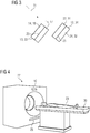
- Fig. 4 shows an X-ray device 27 in a fourth embodiment.
- the x-ray device 27 has the x-ray tube 10 and an x-ray detector 28.
- a patient 29 is positioned on a patient couch 30.
- the x-ray device 27 is designed as a computer tomograph.
- the x-ray device 27 can be part of a mammography device or a C-arm angiography system.
Abstract
Die Erfindung betrifft eine Röntgenröhre, eine Röntgeneinrichtung und eine Mammographieeinrichtung.Die erfindungsgemäße Röntgenröhre weist- einen einen Elektronenstrahl emittierenden Elektronenemitter und- eine mehrschichtige Anode auf,- wobei die mehrschichtige Anode eine dem Elektronenstrahl zugewandte erste Anodenschicht und eine dem Elektronenstrahl abgewandte zweite Anodenschicht aufweist,- wobei die erste Anodenschicht ein erstes Anodenmaterial zur Generierung einer Bremsstrahlung mittels des auftreffenden Elektronenstrahls aufweist,- wobei die zweite Anodenschicht ein zweites Anodenmaterial zur Generierung einer weiteren Röntgenstrahlung mittels der Bremsstrahlung aufweist,- wobei die weitere Röntgenstrahlung monochromatischer ist als die Bremsstrahlung und- wobei die erste Anodenschicht und die zweite Anodenschicht flächig aneinander angrenzen.The invention relates to an X-ray tube, an X-ray device and a mammography device. The X-ray tube according to the invention has an electron emitter emitting an electron beam and a multilayer anode, the multilayer anode having a first anode layer facing the electron beam and a second anode layer facing away from the electron beam, the first anode layer having a first anode material for generating bremsstrahlung by means of the impinging electron beam, - the second anode layer having a second anode material for generating further X-rays by means of the bremsstrahlung, - the further x-rays being more monochromatic than the bremsstrahlung and - the first The anode layer and the second anode layer are flat adjacent to one another.
Description
Die Erfindung betrifft eine Röntgenröhre, eine Röntgeneinrichtung und eine Mammographieeinrichtung.The invention relates to an X-ray tube, an X-ray device and a mammography device.
Für eine bildgebende Untersuchung mit Röntgenstrahlung wird üblicherweise eine Röntgenröhre verwendet. Eine Röntgeneinrichtung weist typischerweise die Röntgenröhre und einen Röntgendetektor zur Durchführung der bildgebenden Untersuchung auf. Die bildgebende Untersuchung kann insbesondere eine bildgebende Mammographieuntersuchung, insbesondere ein Mammographie-Screening, sein. Idealerweise ermöglicht die Röntgenröhre die bildgebende Untersuchung mit einer hohen Bildqualität und gleichermaßen mit einer möglichst niedrigen Röntgenstrahlendosis, vorzugsweise durch eine Anpassung eines Emissionsspektrums der Röntgenstrahlung. Vorzugsweise ist die Röntgenstrahlung bzw. das Emissionsspektrum, insbesondere deren Energieverteilung, in Hinblick auf einen maximalen Bildkontrast abgestimmt. Diesbezüglich ist bekannt, dass die Röntgenstrahlendosis desto geringer ist, je monochromatischer die Röntgenstrahlung bzw. das Emissionsspektrum ist.An X-ray tube is usually used for an imaging examination with X-rays. An x-ray device typically has the x-ray tube and an x-ray detector for performing the imaging examination. The imaging examination can in particular be an imaging mammography examination, in particular a mammography screening. Ideally, the X-ray tube enables the imaging examination with a high image quality and also with the lowest possible X-ray dose, preferably by adapting an emission spectrum of the X-ray radiation. The X-ray radiation or the emission spectrum, in particular its energy distribution, is preferably coordinated with a view to maximum image contrast. In this regard, it is known that the X-ray dose is lower, the more monochromatic the X-ray radiation or the emission spectrum.
Beispielsweise wird herkömmliche Röntgenstrahlung mittels eines Filters angepasst, wobei gleichermaßen die Bildqualität und die Röntgenstrahlendosis optimiert werden soll. Üblicherweise verringert der Filter die für die Bildqualität nützliche Röntgenstrahlung, wodurch zum Ausgleich eine Intensität der Röntgenstrahlung erhöht werden muss. Eine weitere Möglichkeit der Anpassung des Emissionsspektrums ist, dass die Röntgenstrahlung generierende Anodenmaterial zu variieren.For example, conventional X-ray radiation is adapted by means of a filter, the image quality and the X-ray dose to be optimized in the same way. The filter usually reduces the X-ray radiation that is useful for the image quality, as a result of which an intensity of the X-ray radiation must be increased to compensate. Another possibility of adapting the emission spectrum is to vary the anode material generating the X-ray radiation.
Aus der noch nicht veröffentlichen Anmeldung
Die
Der Erfindung liegt die Aufgabe zu Grunde, eine Röntgenröhre, eine Röntgeneinrichtung und eine Mammographieeinrichtung anzugeben, bei welchen ein Anteil an monochromatischer Röntgenstrahlung erhöht wird.The invention is based on the object of specifying an X-ray tube, an X-ray device and a mammography device in which a proportion of monochromatic X-ray radiation is increased.
Die Aufgabe wird durch die Merkmale der unabhängigen Ansprüche gelöst. Vorteilhafte Ausgestaltungen sind in den Unteransprüchen beschrieben.The object is achieved by the features of the independent claims. Advantageous embodiments are described in the subclaims.
Die erfindungsgemäße Röntgenröhre weist
- einen einen Elektronenstrahl emittierenden Elektronenemitter und
- eine mehrschichtige Anode auf,
- wobei die mehrschichtige Anode eine dem Elektronenstrahl zugewandte erste Anodenschicht und eine dem Elektronenstrahl abgewandte zweite Anodenschicht aufweist,
- wobei die erste Anodenschicht ein erstes Anodenmaterial zur Generierung einer Bremsstrahlung mittels des auftreffenden Elektronenstrahls aufweist,
- wobei die zweite Anodenschicht ein zweites Anodenmaterial zur Generierung einer weiteren Röntgenstrahlung mittels der Bremsstrahlung aufweist,
- wobei die weitere Röntgenstrahlung monochromatischer ist als die Bremsstrahlung und
- wobei die erste Anodenschicht und die zweite Anodenschicht flächig aneinander angrenzen.
- an electron emitter emitting an electron beam, and
- a multilayer anode,
- wherein the multilayer anode has a first anode layer facing the electron beam and a second anode layer facing away from the electron beam,
- wherein the first anode layer has a first anode material for generating bremsstrahlung by means of the impinging electron beam,
- wherein the second anode layer has a second anode material for generating a further X-ray radiation by means of the bremsstrahlung,
- the further X-rays being more monochromatic than the bremsstrahlung and
- wherein the first anode layer and the second anode layer adjoin one another areally.
Die Röntgenröhre ist insbesondere vorteilhaft, weil aufgrund der räumlichen Nähe der ersten Anodenschicht zur zweiten Anodenschicht mehr Bremsstrahlung die zweite Anodenschicht durchdringt, wodurch vorzugsweise ein Anteil an monochromatischer Röntgenstrahlung im Emissionsspektrum der Röntgenröhre erhöht ist. In anderen Worten geht weniger Bremsstrahlung außerhalb des zweiten Anodenmaterials verloren. Ein weiterer Vorteil kann sein, dass die zweite Anodenschicht vorzugsweise nicht von Primärelektronen, sondern von Sekundärelektronen getroffen wird. Vorzugsweise kann eine Bildqualität und/oder eine Röntgenstrahlendosis bei einer bildgebenden Untersuchung eines Patienten optimiert werden. Beispielsweise kann die bildgebende Untersuchung eine bildgebende Mammographieuntersuchung, eine Durchleuchtung, eine Angiographie, eine Computertomographie und/oder eine kontrastmittelgestützte Untersuchung umfassen.The X-ray tube is particularly advantageous because, due to the spatial proximity of the first anode layer to the second anode layer, more bremsstrahlung penetrates the second anode layer, which means that a portion of monochromatic X-ray radiation is preferably in the emission spectrum of the X-ray tube is increased. In other words, less bremsstrahlung is lost outside the second anode material. Another advantage can be that the second anode layer is preferably not struck by primary electrons, but by secondary electrons. An image quality and / or an X-ray dose can preferably be optimized during an imaging examination of a patient. For example, the imaging examination can include an imaging mammography examination, fluoroscopy, angiography, computed tomography and / or a contrast agent-assisted examination.
Die Röntgenröhre kann insbesondere gemäß einer Stehanodenröntgenröhre, einer Drehanodenröntgenröhre oder einer Drehkolbenröntgenröhre ausgebildet sein. Typischerweise ist die Röntgenröhre evakuiert. Der Elektronenstrahl weist typischerweise mehrere Elektronen auf, welche von dem Elektronenemitter zu der mehrschichtigen Anode hin vorzugsweise beschleunigt werden. Der Elektronenstrahl wird beispielsweise von einer Ablenkeinheit, insbesondere von einer magnetischen Ablenkeinheit, der Röntgenröhre auf die mehrschichtige Anode ausgerichtet. Der Elektronenemitter kann insbesondere einen Wendelemitter, einen Flachemitter oder einen Feldeffekt-Emitter aufweisen.The x-ray tube can in particular be designed according to a standing anode x-ray tube, a rotating anode x-ray tube or a rotary piston x-ray tube. Typically the X-ray tube is evacuated. The electron beam typically has a plurality of electrons which are preferably accelerated from the electron emitter to the multilayer anode. The electron beam is directed onto the multilayer anode, for example, by a deflection unit, in particular a magnetic deflection unit, of the X-ray tube. The electron emitter can in particular have a helical emitter, a flat emitter or a field effect emitter.
Die mehrschichtige Anode weist insbesondere mehrere Anodenschichten an unterschiedlichen Anodenmaterialien auf. Die erste Anodenschicht kann sich in einer Ausdehnung und/oder in einem Volumen und/oder in einem Gewicht von der zweiten Anodenschicht unterscheiden. Die erste Anodenschicht kann beispielsweise auf die zweite Anodenschicht aufgetragen werden oder umgekehrt. Das Auftragen kann insbesondere ein Sprühen, ein Gießen, ein Befestigen, ein Bedampfen, ein Sputtern, ein selektives elektrochemisches Beschichten und/oder ein Maskieren umfassen. Grundsätzlich ist es denkbar, dass nach dem Auftragen die erste Anodenschicht und/oder die zweite Anodenschicht zumindest teilweise wieder abgetragen wird, insbesondere wenn das Auftragen ohne Maskieren erfolgt. Durch das Auftragen grenzen insbesondere die erste Anodenschicht und die zweite Anodenschicht flächig aneinander an. Typischerweise ist zwischen der ersten Anodenschicht und der zweiten Anodenschicht kein Material und/oder kein Abstand. Die erste Anodenschicht und die zweite Anodenschicht teilen insbesondere einen gemeinsamen flächigen Kontaktbereich. Der gemeinsame flächige Kontaktbereich kann zweidimensional sein, beispielsweise eben, oder dreidimensional verformt sein, beispielsweise wellenförmig oder L-förmig oder U-förmig. Wenn der gemeinsame flächige Kontaktbereich dreidimensional verformt ist, umschließt die erste Anodenschicht zumindest teilweise insbesondere die zweite Anodenschicht oder umgekehrt. Gemäß einer besonderen Ausführungsform umschließt die zweite Anodenschicht die erste Anodenschicht, insbesondere L-förmig oder U-förmig, weil dadurch mehr Bremsstrahlung auf der zweiten Anodenschicht auftreffen kann.The multi-layer anode has, in particular, several anode layers on different anode materials. The first anode layer can differ from the second anode layer in terms of extent and / or in volume and / or in weight. The first anode layer can for example be applied to the second anode layer or vice versa. The application can in particular comprise a spraying, a casting, a fastening, a vapor deposition, a sputtering, a selective electrochemical coating and / or a masking. In principle, it is conceivable that after the application the first anode layer and / or the second anode layer is at least partially removed again, in particular if the application takes place without masking. By the In particular, the first anode layer and the second anode layer adjoin one another flatly. There is typically no material and / or no spacing between the first anode layer and the second anode layer. The first anode layer and the second anode layer share in particular a common flat contact area. The common two-dimensional contact area can be two-dimensional, for example flat, or three-dimensionally deformed, for example wavy or L-shaped or U-shaped. When the common flat contact area is deformed three-dimensionally, the first anode layer at least partially encloses, in particular, the second anode layer or vice versa. According to a particular embodiment, the second anode layer encloses the first anode layer, in particular in an L-shaped or U-shaped manner, because as a result, more bremsstrahlung can impinge on the second anode layer.
Dass die erste Anodenschicht dem Elektronenstrahl zugewandt und dass die zweite Anodenschicht dem Elektronstrahl abgewandt ist, bedeutet insbesondere, dass der Elektronenstrahl vorzugsweise zunächst auf die erste Anodenschicht auftrifft. Die Primärelektronen des Elektronenstrahls treffen vorzugsweise auf der ersten Anodenschicht auf. Die Primärelektronen sind vorzugsweise solche Elektronen, welche noch nicht mit dem ersten Anodenmaterial oder dem zweiten Anodenmaterial wechselgewirkt haben. Elektronen, welche bereits eine Wechselwirkung mit dem ersten Anodenmaterial oder dem zweiten Anodenmaterial durchgeführt haben, sind typischerweise Sekundärelektronen. Die Wechselwirkung kann ein Streuen, ein Fluoreszieren, ein Ablenken, ein Absorbieren und/oder ein Abschwächen sein. Typischerweise wird der Elektronenstrahl von der ersten Anodenschicht vollständig oder zumindest teilweise absorbiert und/oder abgeschwächt. Wenn der Elektronenstrahl teilweise absorbiert wird, kann der Elektronenstrahl nach der ersten Anodenschicht grundsätzlich auf die zweite Anodenschicht auftreffen. Die erste Anodenschicht ist insbesondere zwischen dem Elektronenemitter und der zweiten Anodenschicht angeordnet. Die mehrschichtige Anode ist vorzugsweise relativ zum Elektronenstrahl derart ausgerichtet, dass der Elektronenstrahl zunächst auf der ersten Anodenschicht auftrifft.The fact that the first anode layer faces the electron beam and that the second anode layer faces away from the electron beam means in particular that the electron beam preferably first strikes the first anode layer. The primary electrons of the electron beam preferably strike the first anode layer. The primary electrons are preferably those electrons which have not yet interacted with the first anode material or the second anode material. Electrons that have already interacted with the first anode material or the second anode material are typically secondary electrons. The interaction can be scattering, fluorescing, deflecting, absorbing and / or attenuating. Typically, the electron beam is completely or at least partially absorbed and / or attenuated by the first anode layer. If the electron beam is partially absorbed, the electron beam can in principle impinge on the second anode layer after the first anode layer. The first anode layer is arranged in particular between the electron emitter and the second anode layer. The multilayer anode is preferably relative aligned with the electron beam in such a way that the electron beam initially strikes the first anode layer.
Die erste Anodenschicht kann insbesondere aus dem ersten Anodenmaterial bestehen. Das erste Anodenmaterial ist insbesondere derart ausgebildet, dass aus den auftreffenden Elektronen die Bremsstrahlung generiert werden kann. Das Generieren der Bremsstrahlung erfolgt typischerweise durch ein derartiges Wechselwirken eines eintreffenden Elektrons mit einem Nukleus des ersten Anodenmaterials, dass das eintreffende Elektron abgelenkt und somit um eine Deltaenergie abgeschwächt wird, wobei ein Photon mit der Deltaenergie als Teil der Bremsstrahlung entsteht. Die Bremsstrahlung ist typischerweise eine breitbandige und/oder kontinuierliche Röntgenstrahlung.The first anode layer can in particular consist of the first anode material. The first anode material is designed in particular in such a way that the bremsstrahlung can be generated from the impinging electrons. The bremsstrahlung is typically generated by such an interaction of an incoming electron with a nucleus of the first anode material that the incoming electron is deflected and thus attenuated by a delta energy, a photon with the delta energy being produced as part of the bremsstrahlung. The bremsstrahlung is typically broadband and / or continuous x-ray radiation.
Die zweite Anodenschicht kann insbesondere aus dem zweiten Anodenmaterial bestehen. Das zweite Anodenmaterial kann insbesondere ein Konvertermaterial sein. Das zweite Anodenmaterial ist insbesondere derart ausgebildet, dass aus der vom zweiten Anodenmaterial absorbierten Bremsstrahlung die weitere Röntgenstrahlung generiert werden kann. Das Generieren der weiteren Röntgenstrahlung kann insbesondere durch ein Fluoreszieren des zweiten Anodenmaterials in Abhängigkeit eines eintreffenden Bremsstrahlungsphotons erfolgen. Alternativ oder zusätzlich können von dem ersten Anodenmaterial zurückgestreute Elektronen, insbesondere die Sekundärelektronen, auf das zweite Anodenmaterial treffen, wobei die weitere Röntgenstrahlung beispielsweise durch Fluoreszieren generiert wird. Die weitere Röntgenstrahlung kann insbesondere die Fluoreszenz-Photonen aufweisen. Eine Fluoreszenz-Rate des zweiten Anodenmaterials ist typischerweise höher als eine Fluoreszenz-Rate des ersten Anodenmaterials.The second anode layer can in particular consist of the second anode material. The second anode material can in particular be a converter material. The second anode material is designed in particular such that the further x-ray radiation can be generated from the bremsstrahlung absorbed by the second anode material. The generation of the further X-ray radiation can in particular take place by fluorescing the second anode material as a function of an incoming bremsstrahlung photon. Alternatively or in addition, electrons scattered back from the first anode material, in particular the secondary electrons, can strike the second anode material, the further X-ray radiation being generated, for example, by fluorescence. The further X-ray radiation can in particular have the fluorescence photons. A fluorescence rate of the second anode material is typically higher than a fluorescence rate of the first anode material.
Das erste Anodenmaterial unterscheidet sich insbesondere derart von dem zweiten Anodenmaterial, dass die weitere Röntgenstrahlung monochromatischer ist als die Bremsstrahlung. Das erste Anodenmaterial ist vorzugsweise bevorzugt zur Generierung von der Bremsstrahlung aus den Elektronen geeignet und das zweite Anodenmaterial ist vorzugsweise bevorzugt zur Generierung von der weiteren Röntgenstrahlung aus der Bremsstrahlung geeignet. Dass die weitere Röntgenstrahlung monochromatischer ist als die Bremsstrahlung bedeutet insbesondere, dass ein Emissionsspektrum der Bremsstrahlung im Vergleich zu einem Emissionsspektrum der weiteren Röntgenstrahlung breitbandiger ist. Wenn die weitere Röntgenstrahlung monochromatischer ist, ist das Emissionsspektrum der weiteren Röntgenstrahlung typischerweise durch einen höheren Anteil an charakteristischer Röntgenstrahlung gekennzeichnet, insbesondere durch einen höheren Anteil von Photonen der K-Linien des zweiten Anodenmaterials im Vergleich zum Emissionsspektrum der Bremsstrahlung. Das Emissionsspektrum der weiteren Röntgenstrahlung kann insbesondere mehr und/oder stärkere charakteristische Linien aufweisen als das Emissionsspektrum der Bremsstrahlung.The first anode material differs in particular from the second anode material in such a way that the further x-ray radiation is more monochromatic than the bremsstrahlung. The first anode material is preferably preferred for generation suitable from the bremsstrahlung from the electrons and the second anode material is preferably suitable for generating the further X-ray radiation from the bremsstrahlung. The fact that the further x-ray radiation is more monochromatic than the bremsstrahlung means in particular that an emission spectrum of the bremsstrahlung is broader than an emission spectrum of the further x-ray radiation. If the further x-ray radiation is more monochromatic, the emission spectrum of the further x-ray radiation is typically characterized by a higher proportion of characteristic x-ray radiation, in particular by a higher proportion of photons of the K-lines of the second anode material compared to the emission spectrum of the bremsstrahlung. The emission spectrum of the further X-ray radiation can in particular have more and / or stronger characteristic lines than the emission spectrum of the bremsstrahlung.
Eine Ausführungsform sieht vor, dass sich das erste Anodenmaterial in einer charakteristischen Linie eines Emissionsspektrums von dem zweiten Anodenmaterial unterscheidet. Diese Ausführungsform ist insofern vorteilhaft, weil das erste Anodenmaterial zur Generierung der Bremsstrahlung optimiert sein kann und das zweite Anodenmaterial zur Generierung der weiteren Röntgenstrahlung optimiert sein kann.One embodiment provides that the first anode material differs from the second anode material in a characteristic line of an emission spectrum. This embodiment is advantageous in that the first anode material can be optimized for generating the bremsstrahlung and the second anode material can be optimized for generating the further X-ray radiation.
Eine Ausführungsform sieht vor, dass das erste Anodenmaterial zumindest ein Material der folgenden Liste aufweist:
- Wolfram,
- Gold.
- Tungsten,
- Gold.
Diese Ausführungsform ist vorteilhaft, weil Wolfram besonders hitzebeständig ist und/oder Gold ein besonders vorteilhaftes Emissionsspektrum aufweist.This embodiment is advantageous because tungsten is particularly heat-resistant and / or gold has a particularly advantageous emission spectrum.
Eine Ausführungsform sieht vor, dass das zweite Anodenmaterial zumindest ein Material der folgenden Liste aufweist:
- Zinn,
- Silber,
- Molybdän,
- Palladium.
- Tin,
- Silver,
- Molybdenum,
- Palladium.
Diese Ausführungsform ist insbesondere vorteilhaft, weil ein Emissionsspektrum mit einer bestimmten Mischung der vorstehenden Materialien eine charakteristische Linie im Energiebereich zwischen 20 bis 34 keV aufweist, welche insbesondere für eine bildgebende Mammographieuntersuchung vorteilhaft sein kann. Grundsätzlich sind weitere Mischungen der Materialien denkbar, welche sich typischerweise im jeweiligen Emissionsspektrum, insbesondere in deren charakteristischen Linien, unterscheiden.This embodiment is particularly advantageous because an emission spectrum with a certain mixture of the above materials has a characteristic line in the energy range between 20 to 34 keV, which can be particularly advantageous for an imaging mammography examination. In principle, further mixtures of the materials are conceivable, which typically differ in the respective emission spectrum, in particular in their characteristic lines.
Eine Ausführungsform sieht vor, dass die erste Anodenschicht gemeinsam mit der zweiten Anodenschicht eine Anodenmikrostruktur bildet, wobei die Anodenmikrostruktur entlang einer Oberfläche der mehrschichtigen Anode periodisch wiederkehrend angeordnet ist und wobei der Elektronenstrahl auf der Oberfläche in einem Einfallwinkel kleiner 90° auftrifft. Der Elektronenstrahl trifft insbesondere in einem spitzen Winkel auf die Oberfläche. Der Einfallwinkel kann insbesondere zwischen 10° und 60°, vorzugsweise zwischen 20° und 50° liegen und/oder besonders vorteilhafterweise 45° betragen. Der Einfallwinkel ist typischerweise ein Winkel zwischen dem Elektronenstrahl und einer, insbesondere makroskopischen, Oberfläche der mehrschichtigen Anode. Der Einfallwinkel ist insbesondere unabhängig von der Anordnung und/oder Ausbildung der Anodenmikrostruktur.One embodiment provides that the first anode layer forms an anode microstructure together with the second anode layer, the anode microstructure being arranged recurring periodically along a surface of the multilayer anode and the electron beam impinging on the surface at an angle of incidence less than 90 °. The electron beam hits the surface in particular at an acute angle. The angle of incidence can in particular be between 10 ° and 60 °, preferably between 20 ° and 50 ° and / or particularly advantageously 45 °. The angle of incidence is typically an angle between the electron beam and a, in particular macroscopic, surface of the multilayer anode. The angle of incidence is in particular independent of the arrangement and / or design of the anode microstructure.
Die Anodenmikrostruktur kann kegelförmig sein, insbesondere wenn eine einzelne Anodenmikrostruktur der periodisch wiederkehrenden Anodenmikrostruktur im Schnitt dargestellt wird. Typischerweise bildet die einzelne Anodenmikrostruktur makroskopisch betrachtet eine Rille oder eine Welle. Insbesondere die periodisch wiederkehrende Anodenmikrostruktur bildet eine wellenförmige oder sinusförmige Oberfläche der mehrschichtigen Anode. In anderen Worten ist die Oberfläche der mehrschichtigen Anode typischerweise gerillt. Die Anodenmikrostruktur kann beispielsweise eine maximale Ausdehnung kleiner als 1 mm, vorzugsweise kleiner als 100 µm, besonders vorteilhafterweise kleiner als 10 µm aufweisen. Die maximale Ausdehnung kann beispielsweise einer Höhe des Kegels entsprechen. Dass die Anodenmikrostruktur periodisch wiederkehrend angeordnet ist, umfasst insbesondere ein mehrmaliges Replizieren der Anodenmikrostruktur entlang der Oberfläche. Die mehreren periodisch wiederkehrenden Anodenmikrostrukturen bilden insbesondere die wellenförmige oder sinusförmige Oberfläche der mehrschichtigen Anode. Diese Ausführungsform ist insbesondere vorteilhaft, weil der Elektronenstrahl und/oder die Bremsstrahlung und/oder die weitere Röntgenstrahlung insbesondere vor einem Austritt durch ein Röntgenstrahlungsaustrittfenster mehrmals mit der mehrschichtigen Anode, vorzugsweise mit der periodisch wiederkehrenden Anodenmikrostruktur wechselwirken kann. In dieser Ausführungsform ist vorzugsweise ein Anteil an monochromatischer Röntgenstrahlung durch die periodisch wiederkehrende Anodenmikrostruktur erhöht. Ein weiterer Vorteil kann sein, dass an einem Kegel der Anodenmikrostruktur zurückgestreute Elektronen auf einen weiteren Kegel der Anodenmikrostruktur auftreffen, um die weitere Röntgenstrahlung zu generieren. In anderen Worten wird der Anteil an monochromatischer Röntgenstrahlung dadurch erhöht, dass die mehrschichtige Anode mehrere Kegel, insbesondere Anodenschichten, mit dem zweiten Anodenmaterial zur Generierung der weiteren Röntgenstrahlung aufweist. Ein weiterer Vorteil kann sein, dass die dem Elektronenstrahl zugewandte Fläche der mehrschichtigen Anode, insbesondere des ersten Anodenmaterials vergrößert wird.The anode microstructure can be conical, in particular if a single anode microstructure of the periodically recurring anode microstructure is shown in section. Typically, viewed macroscopically, the individual anode microstructure forms a groove or wave. In particular, the periodically recurring anode microstructure forms a wave-shaped or sinusoidal surface of the multilayer anode. In other words, the surface of the multilayer anode is typically grooved. The anode microstructure can, for example, have a smaller maximum dimension than 1 mm, preferably smaller than 100 μm, particularly advantageously smaller than 10 μm. The maximum extent can for example correspond to a height of the cone. The fact that the anode microstructure is arranged in a periodically recurring manner includes, in particular, a multiple replication of the anode microstructure along the surface. The plurality of periodically recurring anode microstructures form, in particular, the undulating or sinusoidal surface of the multilayer anode. This embodiment is particularly advantageous because the electron beam and / or the bremsstrahlung and / or the further x-ray radiation can interact several times with the multilayer anode, preferably with the periodically recurring anode microstructure, especially before exiting through an x-ray exit window. In this embodiment, a proportion of monochromatic X-ray radiation is preferably increased by the periodically recurring anode microstructure. A further advantage can be that electrons scattered back at a cone of the anode microstructure impinge on a further cone of the anode microstructure in order to generate the further X-rays. In other words, the proportion of monochromatic x-ray radiation is increased in that the multilayer anode has a plurality of cones, in particular anode layers, with the second anode material for generating the further x-ray radiation. Another advantage can be that the surface of the multilayer anode, in particular of the first anode material, facing the electron beam is enlarged.
Eine Ausführungsform sieht vor, dass die mehrschichtige Anode eine dem Elektronenstrahl zugewandte dritte Anodenschicht und eine dem Elektronenstrahl abgewandte vierte Anodenschicht aufweist, wobei die dritte Anodenschicht ein drittes Anodenmaterial zur Generierung der Bremsstrahlung mittels des auftreffenden Elektronenstrahls aufweist, wobei die vierte Anodenschicht ein viertes Anodenmaterial zur Generierung der weiteren Röntgenstrahlung mittels der Bremsstrahlung aufweist, wobei die dritte Anodenschicht und die vierte Anodenschicht flächig aneinander angrenzen und wobei sich das zweite Anodenmaterial in einer charakteristischen Linie eines Emissionsspektrums von dem vierten Anodenmaterial unterscheidet. Die dritte Anodenschicht und die vierte Anodenschicht sind relativ zum Elektronenstrahl insbesondere neben der ersten Anodenschicht und der zweiten Anodenschicht angeordnet. Das zweite Anodenmaterial und das vierte Anodenmaterial können grundsätzlich die gleichen Materialien aufweisen und sich typischerweise in einer Mischung der Materialien unterscheiden. Alternativ ist es denkbar, dass das zweite Anodenmaterial ein Material aufweist, welches das vierte Anodenmaterial nicht aufweist und umgekehrt. Grundsätzlich kann das zweite Anodenmaterial teilweise dieselben charakteristischen Linien aufweisen wie das vierte Anodenmaterial. Das erste Anodenmaterial kann dem dritten Anodenmaterial entsprechen oder alternativ sich in einer charakteristischen Linie von dem dritten Anodenmaterial unterscheiden. Diese Ausführungsform ist insbesondere vorteilhaft, weil die mehrschichtige Anode ein Emissionsspektrum mit mehreren charakteristischen Linien bereitstellen kann. Vorzugsweise kann die Röntgenröhre daher für verschiedene bildgebende Untersuchungen verwendet werden.One embodiment provides that the multilayer anode has a third anode layer facing the electron beam and a fourth anode layer facing away from the electron beam, the third anode layer having a third anode material for generating the bremsstrahlung by means of the incident electron beam, the fourth anode layer having a fourth anode material for generation the further X-ray radiation by means of the bremsstrahlung, the third anode layer and the fourth anode layer adjoin one another flat and wherein the second anode material differs from the fourth anode material in a characteristic line of an emission spectrum. The third anode layer and the fourth anode layer are arranged relative to the electron beam, in particular next to the first anode layer and the second anode layer. The second anode material and the fourth anode material can basically have the same materials and typically differ in a mixture of the materials. Alternatively, it is conceivable that the second anode material has a material that the fourth anode material does not have, and vice versa. In principle, the second anode material can partially have the same characteristic lines as the fourth anode material. The first anode material can correspond to the third anode material or alternatively differ from the third anode material in a characteristic line. This embodiment is particularly advantageous because the multilayer anode can provide an emission spectrum with a plurality of characteristic lines. The X-ray tube can therefore preferably be used for various imaging examinations.
Eine besonders vorteilhafte Ausgestaltung der vorherigen Ausführungsform ist, dass der Elektronenstrahl auf die erste Anodenschicht oder auf die dritte Anodenschicht ausgerichtet ist. Diese Ausführungsform ist insbesondere vorteilhaft, weil die mehrschichtige Anode verschiedene Emissionsspektren bereitstellen kann. Beispielsweise kann in diesem Fall eine bildgebende Untersuchung mit weiterer Röntgenstrahlung der zweiten Anodenschicht oder mit weiterer Röntgenstrahlung der vierten Anodenschicht durchgeführt werden. Alternativ oder zusätzlich kann gemäß einem Dual-Energy-Messprotokoll das Energiespektrum während der bildgebenden Messung alternierend festgelegt werden, insbesondere durch das Ausrichten des Elektronenstrahls auf die erste Anodenschicht oder auf die dritte Anodenschicht.A particularly advantageous embodiment of the previous embodiment is that the electron beam is aligned with the first anode layer or the third anode layer. This embodiment is particularly advantageous because the multilayer anode can provide different emission spectra. For example, in this case an imaging examination can be carried out with further x-rays from the second anode layer or with further x-rays from the fourth anode layer. Alternatively or additionally, according to a dual energy measurement protocol, the energy spectrum can be determined alternately during the imaging measurement, in particular by aligning the electron beam with the first anode layer or the third anode layer.
Eine Ausführungsform sieht vor, dass die Anodenmikrostruktur, insbesondere wie zuvor beschrieben, periodisch wiederkehrend angeordnet ist und ein erster Kegel der Anodenmikrostruktur die erste Anodenschicht sowie die zweite Anodenschicht aufweist und ein zweiter Kegel der Anodenmikrostruktur die dritte Anodenschicht sowie die vierte Anodenschicht aufweist. Diese Ausführungsform ist insofern vorteilhaft, weil eine Röntgenröhre mit einer kompakten mehrschichtigen Anode bereitgestellt wird, welche vorzugsweise verschiedene Emissionsspektren generiert.One embodiment provides that the anode microstructure, in particular as described above, is arranged periodically recurring and a first cone of the anode microstructure has the first anode layer and the second anode layer and a second cone of the anode microstructure has the third anode layer and the fourth anode layer. This embodiment is advantageous in that an X-ray tube is provided with a compact multilayer anode, which preferably generates different emission spectra.
Eine Röntgeneinrichtung weist die Röntgenröhre und einen Röntgendetektor auf. Der Röntgendetektor kann insbesondere die weitere Röntgenstrahlung nach einem Durchleuchten des Patienten erfassen. Mittels der erfassten weiteren Röntgenstrahlung kann vorzugsweise ein medizinisches Bild des Patienten rekonstruiert und/oder in einer Speichereinheit und/oder auf einer Anzeigeeinheit bereitgestellt werden.An x-ray device has the x-ray tube and an x-ray detector. The x-ray detector can in particular detect the further x-ray radiation after the patient has been x-rayed. A medical image of the patient can preferably be reconstructed and / or provided in a memory unit and / or on a display unit by means of the further x-ray radiation detected.
Die Mammographieeinrichtung weist insbesondere die Röntgeneinrichtung und eine Brustlagerungsvorrichtung auf. Auf der Brustlagerungsvorrichtung kann vorzugsweise eine Brust des Patienten, beispielsweise einer Patientin, während der bildgebenden Mammographieuntersuchung gelagert werden.The mammography device has in particular the X-ray device and a breast positioning device. A breast of the patient, for example a patient, can preferably be supported on the breast support device during the imaging mammography examination.
Im Folgenden wird die Erfindung anhand der in den Figuren dargestellten Ausführungsbeispiele näher beschrieben und erläutert. Grundsätzlich werden in der folgenden Figurenbeschreibung im Wesentlichen gleichbleibende Strukturen und Einheiten mit demselben Bezugszeichen wie beim erstmaligen Auftreten der jeweiligen Struktur oder Einheit benannt.The invention is described and explained in more detail below using the exemplary embodiments shown in the figures. Basically, in the following description of the figures, structures and units that remain essentially the same are named with the same reference symbols as when the respective structure or unit first appeared.
Es zeigen:
-
Fig. 1 eine Röntgenröhre in einem ersten Ausführungsbeispiel, -
Fig. 2 eine mehrschichtige Anode in einem zweiten Ausführungsbeispiel, -
Fig. 3 eine mehrschichtige Anode in einem dritten Ausführungsbeispiel und -
Fig. 4 eine Röntgeneinrichtung in einem vierten Ausführungsbeispiel,
-
Fig. 1 an X-ray tube in a first embodiment, -
Fig. 2 a multilayer anode in a second embodiment, -
Fig. 3 a multilayer anode in a third embodiment and -
Fig. 4 an X-ray device in a fourth embodiment,
Die mehrschichtige Anode 13 weist eine dem Elektronenstrahl 11 zugewandte erste Anodenschicht 14 und eine dem Elektronenstrahl 11 abgewandte zweite Anodenschicht 15 auf. Die erste Anodenschicht 14 und die zweite Anodenschicht 15 grenzen flächig aneinander an. Ein gemeinsamer flächiger Kontaktbereich 25 ist in diesem Ausführungsbeispiel zweidimensional, insbesondere eben.The
Die erste Anodenschicht 14 weist ein erstes Anodenmaterial 16 zur Generierung einer Bremsstrahlung mittels des auftreffenden Elektronenstrahls 11 auf. Das erste Anodenmaterial 16 weist beispielsweise zumindest ein Material der folgenden Liste auf:
- Wolfram,
- Gold.
- Tungsten,
- Gold.
Die zweite Anodenschicht 15 weist ein zweites Anodenmaterial 17 zur Generierung einer weiteren Röntgenstrahlung mittels der Bremsstrahlung auf. Das erste Anodenmaterial 16 unterscheidet sich insbesondere von dem zweiten Anodenmaterial 17 in einer charakteristischen Linie eines Emissionsspektrums. Das zweite Anodenmaterial 17 weist beispielsweise zumindest ein Material der folgenden Liste auf:
- Zinn,
- Silber,
- Molybdän,
- Palladium.
- Tin,
- Silver,
- Molybdenum,
- Palladium.
Die weitere Röntgenstrahlung ist monochromatischer als die Bremsstrahlung. Die weitere Röntgenstrahlung kann beispielsweise durch ein Röntgenstrahlungsaustrittfenster 18 aus einem Gehäuse 19 der Röntgenröhre 10 austreten. Innerhalb des Gehäuses 19 ist typischerweise ein Vakuum.The other X-rays are more monochromatic than the bremsstrahlung. The further x-ray radiation can exit a
Die erste Anodenschicht 14 bildet gemeinsam mit der zweiten Anodenschicht 15 eine Anodenmikrostruktur 21. Die Anodenmikrostruktur 21 ist entlang einer Oberfläche 22 der mehrschichtigen Anode 13 periodisch wiederkehrend angeordnet. Die Anodenmikrostruktur 21 ist kegelförmig, wenn einzeln im Schnitt betrachtet. Die periodische wiederkehrenden Anodenmikrostrukturen sind vorzugsweise derart nebeneinander angeordnet, dass sich das erste Anodenmaterial 16 und das zweite Anodenmaterial 17 abwechseln.The first anode layer 14 together with the second anode layer 15 forms an anode microstructure 21. The anode microstructure 21 is arranged along a
Der Elektronenstrahl 11 trifft auf der Oberfläche 22 in einem Einfallwinkel kleiner 90° auf. Die Oberfläche 22 ist wellenförmig und/oder sinusförmig. Eine Unterseite 26 der Oberfläche 22 der mehrschichtigen Anode 13 weist typischerweise Wolfram auf oder ein alternatives hitzebeständiges und/oder wärmeleitendes Kühlmaterial auf. Vorzugweise treffen die Elektronen des Elektronenstrahls 11 die erste Anodenschicht 14 und weniger bis gar nicht die zweite Anodenschicht 15.
Die mehrschichtige Anode 13 weist eine dem Elektronenstrahl 11 zugewandte dritte Anodenschicht 23 und eine dem Elektronenstrahl 11 abgewandte vierte Anodenschicht 24 auf. Die dritte Anodenschicht 23 weist ein drittes Anodenmaterial 31 zur Generierung der Bremsstrahlung mittels des auftreffenden Elektronenstrahls 11 auf. Die vierte Anodenschicht 24 weist ein viertes Anodenmaterial 32 zur Generierung der weiteren Röntgenstrahlung mittels der Bremsstrahlung auf. Die dritte Anodenschicht 23 und die vierte Anodenschicht 24 grenzen flächig aneinander an. Das zweite Anodenmaterial 17 unterscheidet sich in einer charakteristischen Linie eines Emissionsspektrums von dem vierten Anodenmaterial 32.The
Im Vergleich zu dem in
In diesem Ausführungsbeispiel stehen die erste Anodenschicht 14, die zweite Anodenschicht 15, die dritte Anodenschicht 23 und die vierte Anodenschicht 24 in einem Winkel von ungefähr 90° zum Elektronenstrahl, wobei der Einfallwinkel des Elektronenstrahls 11 in Hinblick auf die makroskopische Oberfläche kleiner 90° ist. Grundsätzlich ist ein kleinerer oder größerer Winkel denkbar.In this exemplary embodiment, the first anode layer 14, the second anode layer 15, the third anode layer 23 and the fourth anode layer 24 are at an angle of approximately 90 ° to the electron beam, the angle of incidence of the
Weiterhin ist es denkbar, dass der Elektronenstrahl 11 auf die erste Anodenschicht 14 oder auf die dritte Anodenschicht 23, beispielsweise mittels einer magnetischen Ablenkeinheit der Röntgenröhre 10, ausgerichtet ist. In diesem Fall wird die Bremsstrahlung und die zugehörige weitere Röntgenstrahlung insbesondere mehrheitlich, vorzugsweise zu mehr als 75%, besonders vorteilhafterweise zu mehr als 95%, entweder von der ersten Anodenmikrostruktur 33 oder von der zweiten Anodenmikrostruktur 34 generiert.Furthermore, it is conceivable that the
Obwohl die Erfindung im Detail durch die bevorzugten Ausführungsbeispiele näher illustriert und beschrieben wurde, so ist die Erfindung dennoch nicht durch die offenbarten Beispiele eingeschränkt und andere Variationen können vom Fachmann hieraus abgeleitet werden, ohne den Schutzumfang der Erfindung zu verlassen.Although the invention has been illustrated and described in more detail by the preferred exemplary embodiments, the invention is nevertheless not restricted by the disclosed examples and other variations can be derived therefrom by the person skilled in the art without departing from the scope of protection of the invention.
Claims (10)
Priority Applications (3)
| Application Number | Priority Date | Filing Date | Title |
|---|---|---|---|
| EP19179314.0A EP3751594A1 (en) | 2019-06-11 | 2019-06-11 | X-ray tube |
| US16/891,509 US11361929B2 (en) | 2019-06-11 | 2020-06-03 | X-ray tube |
| CN202010517930.XA CN112071730A (en) | 2019-06-11 | 2020-06-09 | X-ray tube, X-ray apparatus, and mammography apparatus |
Applications Claiming Priority (1)
| Application Number | Priority Date | Filing Date | Title |
|---|---|---|---|
| EP19179314.0A EP3751594A1 (en) | 2019-06-11 | 2019-06-11 | X-ray tube |
Publications (1)
| Publication Number | Publication Date |
|---|---|
| EP3751594A1 true EP3751594A1 (en) | 2020-12-16 |
Family
ID=66821030
Family Applications (1)
| Application Number | Title | Priority Date | Filing Date |
|---|---|---|---|
| EP19179314.0A Pending EP3751594A1 (en) | 2019-06-11 | 2019-06-11 | X-ray tube |
Country Status (3)
| Country | Link |
|---|---|
| US (1) | US11361929B2 (en) |
| EP (1) | EP3751594A1 (en) |
| CN (1) | CN112071730A (en) |
Citations (4)
| Publication number | Priority date | Publication date | Assignee | Title |
|---|---|---|---|---|
| DE2719609A1 (en) * | 1977-05-02 | 1978-11-09 | Richard Dr Bauer | X=Ray tube for medical diagnostics or fluorescence analysis - giving pure spectrum of few monochromatic lines |
| US6487272B1 (en) * | 1999-02-19 | 2002-11-26 | Kabushiki Kaisha Toshiba | Penetrating type X-ray tube and manufacturing method thereof |
| US20040120463A1 (en) * | 2002-12-20 | 2004-06-24 | General Electric Company | Rotating notched transmission x-ray for multiple focal spots |
| US20190030363A1 (en) | 2017-05-19 | 2019-01-31 | Imagine Scientific, Inc. | Monochromatic x-ray systems and methods |
Family Cites Families (21)
| Publication number | Priority date | Publication date | Assignee | Title |
|---|---|---|---|---|
| DE19805290C2 (en) * | 1998-02-10 | 1999-12-09 | Siemens Ag | Monochromatic x-ray source |
| US7180981B2 (en) * | 2002-04-08 | 2007-02-20 | Nanodynamics-88, Inc. | High quantum energy efficiency X-ray tube and targets |
| WO2004023852A2 (en) * | 2002-09-03 | 2004-03-18 | Parker Medical, Inc. | Multiple grooved x-ray generator |
| KR100958225B1 (en) * | 2006-02-01 | 2010-05-17 | 도시바 덴시칸 디바이스 가부시키가이샤 | X-ray source, and fluorescent x-ray analyzing device |
| US7203283B1 (en) * | 2006-02-21 | 2007-04-10 | Oxford Instruments Analytical Oy | X-ray tube of the end window type, and an X-ray fluorescence analyzer |
| DE102007046278A1 (en) * | 2007-09-27 | 2009-04-09 | Siemens Ag | X-ray tube with transmission anode |
| AU2010237049B2 (en) * | 2009-04-16 | 2015-12-03 | Eric H. Silver | Monochromatic x-ray methods and apparatus |
| DE102009033074A1 (en) * | 2009-07-03 | 2011-01-05 | Siemens Aktiengesellschaft | X-ray tube, mammography device and method for generating X-ray images |
| US8576988B2 (en) * | 2009-09-15 | 2013-11-05 | Koninklijke Philips N.V. | Distributed X-ray source and X-ray imaging system comprising the same |
| DE102011079179A1 (en) * | 2011-07-14 | 2013-01-17 | Siemens Aktiengesellschaft | Monochromatic X-ray source |
| WO2013017988A1 (en) * | 2011-08-01 | 2013-02-07 | Koninklijke Philips Electronics N.V. | Generation of multiple x-ray energies |
| CN104364876B (en) * | 2012-06-15 | 2017-05-17 | 西门子公司 | X-ray source, use thereof and method for producing X-rays |
| WO2014044316A1 (en) * | 2012-09-21 | 2014-03-27 | Siemens Aktiengesellschaft | Device having an anode for generating x-radiation |
| JP2014160547A (en) * | 2013-02-19 | 2014-09-04 | Canon Inc | Radiation generating tube and radiation photography system using the same |
| DE102013208103A1 (en) * | 2013-05-03 | 2014-11-06 | Siemens Aktiengesellschaft | X-ray source and imaging system |
| US9543109B2 (en) * | 2013-09-19 | 2017-01-10 | Sigray, Inc. | X-ray sources using linear accumulation |
| US10304580B2 (en) * | 2013-10-31 | 2019-05-28 | Sigray, Inc. | Talbot X-ray microscope |
| CN106061388B (en) * | 2014-01-07 | 2019-03-08 | 杰特克公司 | The micro- imaging of X-ray |
| US9646801B2 (en) * | 2015-04-09 | 2017-05-09 | General Electric Company | Multilayer X-ray source target with high thermal conductivity |
| US10818467B2 (en) * | 2018-02-09 | 2020-10-27 | Imagine Scientific, Inc. | Monochromatic x-ray imaging systems and methods |
| EP3629361B1 (en) | 2018-09-26 | 2020-10-28 | Siemens Healthcare GmbH | X-ray emitter, use of an x-ray emitter and method for producing an x-ray emitter |
-
2019
- 2019-06-11 EP EP19179314.0A patent/EP3751594A1/en active Pending
-
2020
- 2020-06-03 US US16/891,509 patent/US11361929B2/en active Active
- 2020-06-09 CN CN202010517930.XA patent/CN112071730A/en active Pending
Patent Citations (4)
| Publication number | Priority date | Publication date | Assignee | Title |
|---|---|---|---|---|
| DE2719609A1 (en) * | 1977-05-02 | 1978-11-09 | Richard Dr Bauer | X=Ray tube for medical diagnostics or fluorescence analysis - giving pure spectrum of few monochromatic lines |
| US6487272B1 (en) * | 1999-02-19 | 2002-11-26 | Kabushiki Kaisha Toshiba | Penetrating type X-ray tube and manufacturing method thereof |
| US20040120463A1 (en) * | 2002-12-20 | 2004-06-24 | General Electric Company | Rotating notched transmission x-ray for multiple focal spots |
| US20190030363A1 (en) | 2017-05-19 | 2019-01-31 | Imagine Scientific, Inc. | Monochromatic x-ray systems and methods |
Also Published As
| Publication number | Publication date |
|---|---|
| US20200395187A1 (en) | 2020-12-17 |
| CN112071730A (en) | 2020-12-11 |
| US11361929B2 (en) | 2022-06-14 |
Similar Documents
| Publication | Publication Date | Title |
|---|---|---|
| DE2902308C2 (en) | X-ray tube | |
| DE102014202330B3 (en) | Single Source DualEnergy with two filters for X-ray spectrum differentiation on radiator apertures with slotted plate | |
| DE102009002114B4 (en) | Arrangement for electron beam tomography | |
| WO2008037731A2 (en) | X-ray system and method for tomosynthetic scanning | |
| DE102008050352B4 (en) | Multi-beam X-ray device | |
| EP1883093A2 (en) | CT scanner | |
| DE102009057066A1 (en) | An imaging device, a radiation therapy device with such an imaging device, a method for generating an image and a computer program product | |
| EP2252216B1 (en) | Arrangement for three-dimensional electron beam tomography | |
| DE2720840A1 (en) | COLLIMATOR FOR REDUCING RADIATION EXPOSURE AND IMPROVING THE RESOLUTION OF RADIATION DIAGNOSTIC SHEET DISPLAYS | |
| DE2719609C3 (en) | X-ray tube for generating monochromatic X-rays | |
| WO2013007484A1 (en) | Monochromatic x-ray source | |
| WO2004100790A1 (en) | X-ray device with improved efficiency | |
| DE602005006255T2 (en) | ARRANGEMENT AND METHOD FOR OBTAINING IMAGE DATA | |
| WO2019034417A1 (en) | X-ray system and method for the operation thereof | |
| DE102008050353B3 (en) | Circular multi-beam X-ray device | |
| DE10237546B4 (en) | X-ray computed tomography device with filter | |
| EP3751594A1 (en) | X-ray tube | |
| DE102004056110A1 (en) | Rotary piston X-ray radiator used in X-ray medical device comprises X-ray tube having vacuum housing with first partial region rotating with rotating anode | |
| WO2008101470A1 (en) | X-ray computed tomography arrangement | |
| DE102016101787B4 (en) | imaging device | |
| EP2979293A1 (en) | X-ray source and imaging system | |
| DE102007018288B4 (en) | Apparatus for irradiation field control in radiological radiotherapy devices | |
| WO2011113814A1 (en) | Multifocus tube | |
| DE2812644A1 (en) | PROCEDURE AND EQUIPMENT FOR TRANSAXIAL COMPUTER-AIDED ROENTGENTOMOGRAPHY | |
| DE102013225425B4 (en) | X-ray device and method for adjusting the intensity profile generated by an X-ray emitter in a beam of rays |
Legal Events
| Date | Code | Title | Description |
|---|---|---|---|
| PUAI | Public reference made under article 153(3) epc to a published international application that has entered the european phase |
Free format text: ORIGINAL CODE: 0009012 |
|
| STAA | Information on the status of an ep patent application or granted ep patent |
Free format text: STATUS: THE APPLICATION HAS BEEN PUBLISHED |
|
| AK | Designated contracting states |
Kind code of ref document: A1 Designated state(s): AL AT BE BG CH CY CZ DE DK EE ES FI FR GB GR HR HU IE IS IT LI LT LU LV MC MK MT NL NO PL PT RO RS SE SI SK SM TR |
|
| AX | Request for extension of the european patent |
Extension state: BA ME |
|
| STAA | Information on the status of an ep patent application or granted ep patent |
Free format text: STATUS: REQUEST FOR EXAMINATION WAS MADE |
|
| 17P | Request for examination filed |
Effective date: 20210604 |
|
| RBV | Designated contracting states (corrected) |
Designated state(s): AL AT BE BG CH CY CZ DE DK EE ES FI FR GB GR HR HU IE IS IT LI LT LU LV MC MK MT NL NO PL PT RO RS SE SI SK SM TR |
|
| RAP1 | Party data changed (applicant data changed or rights of an application transferred) |
Owner name: SIEMENS HEALTHINEERS AG |
|
| GRAP | Despatch of communication of intention to grant a patent |
Free format text: ORIGINAL CODE: EPIDOSNIGR1 |
|
| STAA | Information on the status of an ep patent application or granted ep patent |
Free format text: STATUS: GRANT OF PATENT IS INTENDED |