EP3751591A1 - Steckdosen-baueinheit - Google Patents
Steckdosen-baueinheit Download PDFInfo
- Publication number
- EP3751591A1 EP3751591A1 EP19179212.6A EP19179212A EP3751591A1 EP 3751591 A1 EP3751591 A1 EP 3751591A1 EP 19179212 A EP19179212 A EP 19179212A EP 3751591 A1 EP3751591 A1 EP 3751591A1
- Authority
- EP
- European Patent Office
- Prior art keywords
- socket
- socket unit
- residual current
- unit
- breaker
- Prior art date
- Legal status (The legal status is an assumption and is not a legal conclusion. Google has not performed a legal analysis and makes no representation as to the accuracy of the status listed.)
- Withdrawn
Links
- 239000004020 conductor Substances 0.000 description 5
- 230000001419 dependent effect Effects 0.000 description 3
- 238000009434 installation Methods 0.000 description 3
- RYGMFSIKBFXOCR-UHFFFAOYSA-N Copper Chemical compound [Cu] RYGMFSIKBFXOCR-UHFFFAOYSA-N 0.000 description 2
- 229910052802 copper Inorganic materials 0.000 description 2
- 239000010949 copper Substances 0.000 description 2
- 241001465754 Metazoa Species 0.000 description 1
- 230000007547 defect Effects 0.000 description 1
- 238000009413 insulation Methods 0.000 description 1
- 230000001681 protective effect Effects 0.000 description 1
- 239000013589 supplement Substances 0.000 description 1
Images

Classifications
-
- H—ELECTRICITY
- H01—ELECTRIC ELEMENTS
- H01H—ELECTRIC SWITCHES; RELAYS; SELECTORS; EMERGENCY PROTECTIVE DEVICES
- H01H83/00—Protective switches, e.g. circuit-breaking switches, or protective relays operated by abnormal electrical conditions otherwise than solely by excess current
- H01H83/14—Protective switches, e.g. circuit-breaking switches, or protective relays operated by abnormal electrical conditions otherwise than solely by excess current operated by imbalance of two or more currents or voltages, e.g. for differential protection
- H01H83/144—Protective switches, e.g. circuit-breaking switches, or protective relays operated by abnormal electrical conditions otherwise than solely by excess current operated by imbalance of two or more currents or voltages, e.g. for differential protection with differential transformer
-
- H—ELECTRICITY
- H01—ELECTRIC ELEMENTS
- H01H—ELECTRIC SWITCHES; RELAYS; SELECTORS; EMERGENCY PROTECTIVE DEVICES
- H01H71/00—Details of the protective switches or relays covered by groups H01H73/00 - H01H83/00
- H01H2071/006—Provisions for user interfaces for electrical protection devices
-
- H—ELECTRICITY
- H01—ELECTRIC ELEMENTS
- H01H—ELECTRIC SWITCHES; RELAYS; SELECTORS; EMERGENCY PROTECTIVE DEVICES
- H01H71/00—Details of the protective switches or relays covered by groups H01H73/00 - H01H83/00
- H01H71/10—Operating or release mechanisms
- H01H71/12—Automatic release mechanisms with or without manual release
- H01H71/123—Automatic release mechanisms with or without manual release using a solid-state trip unit
- H01H71/125—Automatic release mechanisms with or without manual release using a solid-state trip unit characterised by sensing elements, e.g. current transformers
-
- H—ELECTRICITY
- H01—ELECTRIC ELEMENTS
- H01R—ELECTRICALLY-CONDUCTIVE CONNECTIONS; STRUCTURAL ASSOCIATIONS OF A PLURALITY OF MUTUALLY-INSULATED ELECTRICAL CONNECTING ELEMENTS; COUPLING DEVICES; CURRENT COLLECTORS
- H01R13/00—Details of coupling devices of the kinds covered by groups H01R12/70 or H01R24/00 - H01R33/00
- H01R13/66—Structural association with built-in electrical component
- H01R13/70—Structural association with built-in electrical component with built-in switch
- H01R13/713—Structural association with built-in electrical component with built-in switch the switch being a safety switch
- H01R13/7135—Structural association with built-in electrical component with built-in switch the switch being a safety switch with ground fault protector
Definitions
- the object of the invention is a socket unit comprising an enclosure, inside which enclosure is arranged a socket, the socket comprising an integral residual current circuit-breaker.
- a residual current circuit-breaker is a sensitive protective device, which in dangerous operating conditions supplements the protection provided by fuses.
- a residual current circuit-breaker trips to de-energize the current circuit quickly, if an insulation fault starts to occur in electrical equipment or electrical wires, which fault could produce leakage current that is dangerous to a person.
- An ordinary fuse is not able to detect and trip this kind of low current defect.
- residual current protection disconnects the current supply very quickly, within less than 30 ms. Thus, even in the worst fault situation a person will not receive a life-threatening electric shock.
- Fault currents can travel to ground also in other ways than through people or animals, e.g. as surface discharge currents in parts of the building. In this case there is always the risk of a fire.
- a residual current circuit-breaker operates as follows. When the electrical device functions normally, the electric current going into it and coming out of it is of the same magnitude. Differences between the ingoing and outcoming electric current arises when a fault current phenomenon occurs. A residual current circuit-breaker monitors the amount of current entering the electrical device and leaving it. As long as these currents are of the same magnitudes, the passage of the electric current is unimpeded. If a part of the electric current travels to earth as fault current, the residual current circuit-breaker then detects a difference between the incoming and outgoing current amounts. At the moment when the amount of fault current reaches a dangerous limit or exceeds it, the current supply is disconnected.
- a residual current circuit breaker comprises a magnetic tripping device or corresponding electronic circuit controlling a relay.
- the aim of the present invention is to provide an improved double socket unit to be flush mounted in single junction box, the socket unit being provided with a residual current circuit-breaker.
- the aim of the invention is achieved with a socket unit according to claim 1.
- the double socket unit according to the invention comprises a casing part, inside which is arranged a socket, the socket comprising an integral residual current circuit-breaker. Additionally, a second socket is arranged inside the same casing part, which second socket is connected to the output connectors of the socket provided with residual current protection, in which case both sockets inside the casing part have residual current protection.
- the socket unit according to the invention has many advantages.
- both the socket provided with a residual current circuit-breaker and the second socket are installable into a single junction box, in which case two separate junction boxes are not needed nor are conductors connecting them.
- the wiring connecting the socket of the socket unit provided with residual current protection and the second socket can be provided with an external actuator with which the current supply to the second socket can be controlled.
- the current supply of the second socket can, if necessary, be disconnected at the same time as the voltage in the socket provided with residual current protection is maintained.
- the actuator of the external control can be placed below the socket unit, inside its junction box or inside the casing part of the socket unit, in which case the actuator is placed in connection with the second socket.
- the single sockets on the market have a fixed conductor between the sockets, generally with uninsulated copper busbars, in which case external control of only the second socket, according to the invention, cannot be implemented.
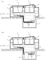
- the drawings present schematic views of partially-sectioned, flush-mounted, double socket units 12.
- the socket unit 12 comprises a casing part 1, 9 in which a socket 2 is arranged, in which socket is an integral residual current circuit-breaker 13.
- the socket 2 is protectively earthed.
- the protectively earthed output of the socket 2 is presented with the reference number 8.
- the residual current circuit-breaker 13 is integrated into the socket 2 in such a way that the electric current travels via the residual current circuit-breaker 13 to the output connectors 5 of the socket 2 and to the output 8.
- the casing part comprises a lid part 1 and a base part 9.
- the socket unit 12 is installable in a junction box 4 ( Fig. 1 ) to be sunk into a wall or into some other mounting base.
- the residual current circuit-breaker 13 can be either of the voltage-dependent type or of the voltage-independent type.
- a voltage-independent residual current circuit-breaker only trips in a fault current situation, but the controllable output contact does not open in conjunction with e.g. a voltage outage, and thus does not need re-adjustment when the voltage has returned.
- Residual current protection can be used e.g. to protect the sockets of a freezer. The device connected to the socket operates normally when the voltage has returned.
- a voltage-dependent residual current circuit-breaker also trips only in a fault current situation, but the controllable output contact opens in conjunction with e.g. a voltage outage, and thus requires re-adjustment of the residual current circuit-breaker when the voltage has returned.
- This kind of residual current circuit-breaker cannot be used e.g. to protect the sockets of a freezer. The device connected to the socket does not operate normally when the voltage has returned.
- Voltage-dependent residual current circuit-breakers can be made to be substantially smaller in size than voltage-independent models, but their use is more restricted, as described above.
- the socket unit 12 comprises a second socket 3 that is connected to the output connectors 5 of the socket 2.
- the residual current circuit-breaker 13 disconnects the current supply both to the socket 2 and to the second socket 3 if the electrical device connected to either one enters a fault situation in which the residual current circuit-breaker 13 trips.
- both sockets 2, 3 have residual current protection.
- the second socket 3 does not comprise its own separate residual current circuit-breaker.
- the second socket 3 is connected to the output connectors 5 of the socket 2 with conductors 6, e.g. with wires.
- the second socket 3 is protectively earthed.
- the protectively earthed output of the second socket 3 is presented with the reference number 7.
- the second socket 3 is situated inside the same casing part 1, 9 as the socket 2.
- the conductors 6 can be provided with an external actuator 14, as presented in Figs. 2 , 3 and 4 .
- the current supply to the second socket 3 can then be disconnected and connected.
- the actuator 14 can be a relay or some other switch suited to the purpose.
- the actuator 14 of the external control can be disposed below the socket unit 12, inside its installation mounting box 4 ( Fig. 2 ).
- the actuator 14 of the external control can also be disposed inside the surface mounting box 10 ( Fig. 3 ) or inside the surface mounting enclosure 11 replacing the base part 9 of the casing part, being thus situated in connection with the second socket 3, ( Fig. 4 ).
- the actuator 14 can be provided with wireless control.
- the double sockets on the market are implemented with a fixed busbar between the sockets, generally with uninsulated copper conductors, in which case external control, according to the invention, of only the second socket cannot be implemented.
- a surface mounting box 10 is connected to the base part 9 of the casing part 1, 9 in which case a surface-mounted assembly is formed from the socket unit 12.
- a separate surface mounting enclosure 11 is connected to the lid part 1 of the casing part, the enclosure replacing the base part 9, in which case a surface-mounted assembly is formed from the socket unit 12.
- a flip lid 15 forming IP 44 enclosure class protection and on top of the socket 2 is a flip lid 16 forming IP 44 enclosure class protection.
Landscapes
- Engineering & Computer Science (AREA)
- Power Engineering (AREA)
- Breakers (AREA)
Priority Applications (1)
| Application Number | Priority Date | Filing Date | Title |
|---|---|---|---|
| EP19179212.6A EP3751591A1 (de) | 2019-06-10 | 2019-06-10 | Steckdosen-baueinheit |
Applications Claiming Priority (1)
| Application Number | Priority Date | Filing Date | Title |
|---|---|---|---|
| EP19179212.6A EP3751591A1 (de) | 2019-06-10 | 2019-06-10 | Steckdosen-baueinheit |
Publications (1)
| Publication Number | Publication Date |
|---|---|
| EP3751591A1 true EP3751591A1 (de) | 2020-12-16 |
Family
ID=67001521
Family Applications (1)
| Application Number | Title | Priority Date | Filing Date |
|---|---|---|---|
| EP19179212.6A Withdrawn EP3751591A1 (de) | 2019-06-10 | 2019-06-10 | Steckdosen-baueinheit |
Country Status (1)
| Country | Link |
|---|---|
| EP (1) | EP3751591A1 (de) |
Citations (4)
| Publication number | Priority date | Publication date | Assignee | Title |
|---|---|---|---|---|
| CN101226861A (zh) * | 2008-01-30 | 2008-07-23 | 陈贵 | 插座式的接地故障线路断路器 |
| WO2009137817A1 (en) * | 2008-05-08 | 2009-11-12 | Outsmart Power Systems Llc | Device and method for measuring current and power in a plug or receptacle |
| CN201532918U (zh) * | 2009-07-21 | 2010-07-21 | 上海益而益电器制造有限公司 | 插座式剩余电流断路器 |
| EP2783435A1 (de) * | 2011-11-24 | 2014-10-01 | Etherma Skandinavia Oy | Fassung |
-
2019
- 2019-06-10 EP EP19179212.6A patent/EP3751591A1/de not_active Withdrawn
Patent Citations (4)
| Publication number | Priority date | Publication date | Assignee | Title |
|---|---|---|---|---|
| CN101226861A (zh) * | 2008-01-30 | 2008-07-23 | 陈贵 | 插座式的接地故障线路断路器 |
| WO2009137817A1 (en) * | 2008-05-08 | 2009-11-12 | Outsmart Power Systems Llc | Device and method for measuring current and power in a plug or receptacle |
| CN201532918U (zh) * | 2009-07-21 | 2010-07-21 | 上海益而益电器制造有限公司 | 插座式剩余电流断路器 |
| EP2783435A1 (de) * | 2011-11-24 | 2014-10-01 | Etherma Skandinavia Oy | Fassung |
Similar Documents
| Publication | Publication Date | Title |
|---|---|---|
| CN103238192B (zh) | 模块化变电站 | |
| US6882257B2 (en) | Earth Leakage Breaker | |
| US9124090B2 (en) | Combined circuit breaker and DC power supply apparatus, systems, and methods | |
| EP0769197A1 (de) | Modul zur verwendung eines miniatur lastschalters | |
| US12155182B2 (en) | Electrical equipment with additional compartment and wiring to account for temperature limitations of connected conductors | |
| CN103683225B (zh) | 核电站低压配电系统全供电范围接地故障保护方法 | |
| US5204800A (en) | Voltage surge suppression device | |
| EP2194628B1 (de) | Fehlerschutzsystem für einen Netzwerkbereich eines Hochspannungsverteilernetzwerks | |
| NO20073530L (no) | Hovedbryteranordning for back up beskyttelse mot elektrisk stot i jordbeskyttet forbruksinstallasjon, med nettspenningsavhengig feilstromutlosning og hoy selektivitet | |
| US3113245A (en) | Ground fault responsive protective system for electric power distribution apparatus | |
| EP1724803B1 (de) | Zu einer elektrischen Schaltvorrichtung zuordenbare elektronische Einrichtung | |
| EP1944786A1 (de) | Fehlerstromschutzschalter | |
| JP2002315183A (ja) | 配電システム | |
| KR102103952B1 (ko) | 일체형 특고압 수배전 장치 | |
| KR20200022662A (ko) | 일체형 특고압 수전장치 | |
| JP2000149758A (ja) | 漏電検出装置 | |
| WO2005039010A1 (en) | An electrical fixture | |
| CN116435149A (zh) | 低压保护开关设备和组装方法 | |
| CN116435121A (zh) | 单极壳体模块和低压保护开关设备 | |
| US6356460B1 (en) | Elevated neutral base for switches | |
| GB2373112A (en) | Method and apparatus for protecting against hazardous voltages on electrical installations | |
| CN104347321B (zh) | 具有坚实中性线的低压剩余电流装置 | |
| Harris et al. | Ring main distribution switchgear-latest trends in use, control and operation | |
| KR100859326B1 (ko) | 수배전반 | |
| Fox et al. | A new standard for electrical apparatus applications in industry |
Legal Events
| Date | Code | Title | Description |
|---|---|---|---|
| PUAI | Public reference made under article 153(3) epc to a published international application that has entered the european phase |
Free format text: ORIGINAL CODE: 0009012 |
|
| STAA | Information on the status of an ep patent application or granted ep patent |
Free format text: STATUS: THE APPLICATION HAS BEEN PUBLISHED |
|
| AK | Designated contracting states |
Kind code of ref document: A1 Designated state(s): AL AT BE BG CH CY CZ DE DK EE ES FI FR GB GR HR HU IE IS IT LI LT LU LV MC MK MT NL NO PL PT RO RS SE SI SK SM TR |
|
| AX | Request for extension of the european patent |
Extension state: BA ME |
|
| STAA | Information on the status of an ep patent application or granted ep patent |
Free format text: STATUS: THE APPLICATION IS DEEMED TO BE WITHDRAWN |
|
| 18D | Application deemed to be withdrawn |
Effective date: 20210617 |