EP3751300A1 - Reconstruction of spiral k-space sampled magnetic resonance images - Google Patents
Reconstruction of spiral k-space sampled magnetic resonance images Download PDFInfo
- Publication number
- EP3751300A1 EP3751300A1 EP19179993.1A EP19179993A EP3751300A1 EP 3751300 A1 EP3751300 A1 EP 3751300A1 EP 19179993 A EP19179993 A EP 19179993A EP 3751300 A1 EP3751300 A1 EP 3751300A1
- Authority
- EP
- European Patent Office
- Prior art keywords
- magnetic resonance
- image
- resonance imaging
- equations
- fat
- Prior art date
- Legal status (The legal status is an assumption and is not a legal conclusion. Google has not performed a legal analysis and makes no representation as to the accuracy of the status listed.)
- Withdrawn
Links
Images




Classifications
-
- G—PHYSICS
- G01—MEASURING; TESTING
- G01R—MEASURING ELECTRIC VARIABLES; MEASURING MAGNETIC VARIABLES
- G01R33/00—Arrangements or instruments for measuring magnetic variables
- G01R33/20—Arrangements or instruments for measuring magnetic variables involving magnetic resonance
- G01R33/44—Arrangements or instruments for measuring magnetic variables involving magnetic resonance using nuclear magnetic resonance [NMR]
- G01R33/48—NMR imaging systems
- G01R33/54—Signal processing systems, e.g. using pulse sequences ; Generation or control of pulse sequences; Operator console
- G01R33/56—Image enhancement or correction, e.g. subtraction or averaging techniques, e.g. improvement of signal-to-noise ratio and resolution
- G01R33/565—Correction of image distortions, e.g. due to magnetic field inhomogeneities
- G01R33/56563—Correction of image distortions, e.g. due to magnetic field inhomogeneities caused by a distortion of the main magnetic field B0, e.g. temporal variation of the magnitude or spatial inhomogeneity of B0
-
- G—PHYSICS
- G01—MEASURING; TESTING
- G01R—MEASURING ELECTRIC VARIABLES; MEASURING MAGNETIC VARIABLES
- G01R33/00—Arrangements or instruments for measuring magnetic variables
- G01R33/20—Arrangements or instruments for measuring magnetic variables involving magnetic resonance
- G01R33/44—Arrangements or instruments for measuring magnetic variables involving magnetic resonance using nuclear magnetic resonance [NMR]
- G01R33/48—NMR imaging systems
- G01R33/54—Signal processing systems, e.g. using pulse sequences ; Generation or control of pulse sequences; Operator console
- G01R33/56—Image enhancement or correction, e.g. subtraction or averaging techniques, e.g. improvement of signal-to-noise ratio and resolution
- G01R33/5608—Data processing and visualization specially adapted for MR, e.g. for feature analysis and pattern recognition on the basis of measured MR data, segmentation of measured MR data, edge contour detection on the basis of measured MR data, for enhancing measured MR data in terms of signal-to-noise ratio by means of noise filtering or apodization, for enhancing measured MR data in terms of resolution by means for deblurring, windowing, zero filling, or generation of gray-scaled images, colour-coded images or images displaying vectors instead of pixels
-
- A—HUMAN NECESSITIES
- A61—MEDICAL OR VETERINARY SCIENCE; HYGIENE
- A61B—DIAGNOSIS; SURGERY; IDENTIFICATION
- A61B5/00—Measuring for diagnostic purposes; Identification of persons
- A61B5/05—Detecting, measuring or recording for diagnosis by means of electric currents or magnetic fields; Measuring using microwaves or radio waves
- A61B5/053—Measuring electrical impedance or conductance of a portion of the body
- A61B5/0537—Measuring body composition by impedance, e.g. tissue hydration or fat content
-
- G—PHYSICS
- G01—MEASURING; TESTING
- G01R—MEASURING ELECTRIC VARIABLES; MEASURING MAGNETIC VARIABLES
- G01R33/00—Arrangements or instruments for measuring magnetic variables
- G01R33/20—Arrangements or instruments for measuring magnetic variables involving magnetic resonance
- G01R33/44—Arrangements or instruments for measuring magnetic variables involving magnetic resonance using nuclear magnetic resonance [NMR]
- G01R33/48—NMR imaging systems
- G01R33/4818—MR characterised by data acquisition along a specific k-space trajectory or by the temporal order of k-space coverage, e.g. centric or segmented coverage of k-space
-
- G—PHYSICS
- G01—MEASURING; TESTING
- G01R—MEASURING ELECTRIC VARIABLES; MEASURING MAGNETIC VARIABLES
- G01R33/00—Arrangements or instruments for measuring magnetic variables
- G01R33/20—Arrangements or instruments for measuring magnetic variables involving magnetic resonance
- G01R33/44—Arrangements or instruments for measuring magnetic variables involving magnetic resonance using nuclear magnetic resonance [NMR]
- G01R33/48—NMR imaging systems
- G01R33/4818—MR characterised by data acquisition along a specific k-space trajectory or by the temporal order of k-space coverage, e.g. centric or segmented coverage of k-space
- G01R33/4824—MR characterised by data acquisition along a specific k-space trajectory or by the temporal order of k-space coverage, e.g. centric or segmented coverage of k-space using a non-Cartesian trajectory
-
- G—PHYSICS
- G01—MEASURING; TESTING
- G01R—MEASURING ELECTRIC VARIABLES; MEASURING MAGNETIC VARIABLES
- G01R33/00—Arrangements or instruments for measuring magnetic variables
- G01R33/20—Arrangements or instruments for measuring magnetic variables involving magnetic resonance
- G01R33/44—Arrangements or instruments for measuring magnetic variables involving magnetic resonance using nuclear magnetic resonance [NMR]
- G01R33/48—NMR imaging systems
- G01R33/4828—Resolving the MR signals of different chemical species, e.g. water-fat imaging
-
- G—PHYSICS
- G01—MEASURING; TESTING
- G01R—MEASURING ELECTRIC VARIABLES; MEASURING MAGNETIC VARIABLES
- G01R33/00—Arrangements or instruments for measuring magnetic variables
- G01R33/20—Arrangements or instruments for measuring magnetic variables involving magnetic resonance
- G01R33/44—Arrangements or instruments for measuring magnetic variables involving magnetic resonance using nuclear magnetic resonance [NMR]
- G01R33/48—NMR imaging systems
- G01R33/54—Signal processing systems, e.g. using pulse sequences ; Generation or control of pulse sequences; Operator console
- G01R33/56—Image enhancement or correction, e.g. subtraction or averaging techniques, e.g. improvement of signal-to-noise ratio and resolution
- G01R33/565—Correction of image distortions, e.g. due to magnetic field inhomogeneities
- G01R33/56527—Correction of image distortions, e.g. due to magnetic field inhomogeneities due to chemical shift effects
-
- G—PHYSICS
- G06—COMPUTING OR CALCULATING; COUNTING
- G06T—IMAGE DATA PROCESSING OR GENERATION, IN GENERAL
- G06T5/00—Image enhancement or restoration
- G06T5/80—Geometric correction
-
- G—PHYSICS
- G06—COMPUTING OR CALCULATING; COUNTING
- G06T—IMAGE DATA PROCESSING OR GENERATION, IN GENERAL
- G06T2207/00—Indexing scheme for image analysis or image enhancement
- G06T2207/10—Image acquisition modality
- G06T2207/10072—Tomographic images
- G06T2207/10088—Magnetic resonance imaging [MRI]
Definitions
- the invention relates to Magnetic Resonance Imaging, in particular to the reconstruction of magnetic resonance images from spirally sampled k-space data.
- a large static magnetic field is used by Magnetic Resonance Imaging (MRI) scanners to align the nuclear spins of atoms as part of the procedure for producing images within the body of a patient.
- This large static magnetic field is referred to as the B0 field or the main magnetic field.
- Various quantities or properties of the subject can be measured spatially using MRI. Images are reconstructed from magnetic resonance imaging data that is sampled in k-space.
- the k-space data may be acquired using a variety of different sampling patterns.
- One example is the sampling of k-space data using a spiral sampling pattern.
- K-space sampling patters may be vulnerable to spatial and temporal variations of the static magnetic field, which may result in image artifacts.
- a k-space energy spectrum analysis algorithm is used to generate a B0 map from the k-space data at each time point.
- a simulated phase evolution rewinding algorithm is then used with a residual deblurring algorithm to correct for the blurring caused by both spatial and temporal B0.
- Dixon methods of magnetic resonance imaging include a family of techniques for producing separate water and lipid (fat) images.
- the various Dixon techniques such as, but not limited to, two-point Dixon Method, three-point Dixon method, four-point Dixon method, and six-point Dixon Method are collectively referred to herein as Dixon techniques or methods.
- Dixon techniques or methods There are typically multiple solutions when reconstructing the water and fat images. It is possible to inadvertently switch voxels between the water and fat images; this is referred to a water-fat swap herein.
- the invention provides for a medical system, a method, and a computer program product in the independent claims. Embodiments are given in the dependent claims.
- Embodiments may provide for an improved method of removing artifacts due to the use of a spiral k-space sampling pattern. This may be achieved by calculating the clinical images numerically from measured preliminary magnetic resonance images using a first set of equations. To remove the artifacts additional regularization equations (second set of equations) are included in the numerical solver.
- This technique can be applied in several ways.
- prior knowledge such as provided by a water and/or fat mask can be used to reduce the number of artifacts.
- a regularization matrix with off diagonal terms i.e. a non-diagonal regularization matrix
- a non-diagonal regularization matrix can be used to reduce or eliminate image artifacts such as blurring or ringing effects.
- the use of a non-diagonal regularization matrix may also be applied to Dixon imaging.
- the invention provides for a medical system that comprises a memory which stores machine-executable instructions.
- the medical system further comprises a processor.
- Execution of the machine-executable instructions causes the processor to receive magnetic resonance imaging data.
- the magnetic resonance imaging data has a spiral k-space sampling pattern.
- Execution of the machine-executable instructions further causes the processor to reconstruct at least one preliminary magnetic resonance image from the magnetic resonance imaging data.
- Execution of the machine-executable instructions further cause the processor to construct a first set of equations comprising each of the at least one of preliminary magnetic resonance images being equal to an image transformation of at least one clinical image.
- the image transformation makes use of a first spatially dependent kernel for each of the at least one clinical image.
- the first spatially dependent kernel may for example be used to make a convolution of all of the clinical images to arrive at the individual preliminary magnetic resonance images.
- Execution of the machine-executable instructions further causes the processor to construct a second set of equations comprising at least one regularization matrix times the at least one clinical image.
- the at least one regularization matrix times the at least one clinical image could be set to be equal to zero to provide regularization equations.
- Execution of the machine-executable instructions further causes the processor to numerically solve the first set of equations and the second set of equations simultaneously for the at least one clinical image.
- the numerical solution of the at least one clinical image may be considered to be an inverse problem.
- the at least one preliminary magnetic resonance image are the images that are measured or determined experimentally and then the at least one clinical image is determined numerically from these preliminary magnetic resonance image or images.
- a medical system as used herein may in some examples encompass a computer system which is programmed for performing the image processing and magnetic resonance imaging construction techniques that are performed by the processor.
- This functionality may for example be integrated into different types of systems. It may be available remotely via a cloud system. It may for example be a workstation that is for example being used in a radiology or other medical center.
- the functionality may also be incorporated into a medical imaging scanner such as a magnetic resonance imaging system.
- the embodiment may be beneficial because it may provide for a means of removing artifacts from magnetic resonance images. In particular it may be efficient in removing artifacts from images that have a spiral k-space sampling pattern.
- the simultaneous solution of the first set of equations and the second set of equations results in a removal of artifacts caused by the spiral k-space sampling pattern from the at least one clinical image.
- each of the at least one clinical image represents a concentration of one type of a molecular species.
- This embodiment may be beneficial because it may be useful in various types of magnetic resonance imaging protocols where various types of material such as fat, water, or spinal fluid are suppressed.
- the at least one clinical image is a Dixon water image and a fat image.
- the image transformation comprises a convolution of the Dixon water image and the Dixon fat image using the first spatially dependent kernel for each of the at least one clinical image. This embodiment may be beneficial because it may provide for a means of providing for improved Dixon water images and Dixon fat images.
- the at least one regularization matrix comprises a water regularization matrix and a fat regularization matrix. That is to say the Dixon water image has its own water regularization matrix and the Dixon fat image has its own fat regularization matrix.
- the construction of the second set of equations is performed by multiplying the water regularization matrix times a matrix representation of the Dixon water image.
- the construction of the second set of equations is further performed by multiplying the fat regularization matrix times a matrix representation of the Dixon fat image.
- equations may be constructed such that zero is set equal to the water regularization matrix times the matrix representation of the Dixon water image and again, zero is set equal to the multiple of the fat regularization matrix times the matrix representation of the Dixon fat image.
- execution of the instructions further causes the processor to perform the multiplication of the water regularization matrix times a water mask before constructing the second set of equations.
- a water mask as used herein is a mask or image which is used to indicate a known location of water or water voxels within the magnetic resonance image. For example, a low resolution or other information may be used to provide this information a fortiori. This may improve water and fat separation during the reconstruction.
- Execution of the machine-executable instructions further causes the processor to multiply the fat regularization matrix times a fat mask before constructing the second set of equations.
- the fat mask is a mask which is used to indicate either a presence or even a concentration of fat within various voxels. This information may be known before the reconstruction for example from lower resolution scans or other information.
- the water mask and the fat mask may be considered to be combining prior knowledge of the location or concentration of fat and water within the subject to improve the reconstruction of the Dixon water image and the Dixon fat image.
- the water and fat masks may be used to indicate a concentration or partial volume of water or fat within a particular voxel. In some instances, this information is obtained through separate imaging or information. In other examples these masks could for example be from a prior iteration of trying to construct the Dixon water image and the Dixon fat image.
- the water mask comprises a per voxel water value inversely proportional to a water content of each voxel in the Dixon water image.
- the fat mask comprises a fat value inversely proportional to a fat content of each voxel in the Dixon fat image.
- the at least one regularization matrix is a non-diagonal matrix.
- the use of a non-diagonal matrix as a regularization matrix may have the advantage that the regularization term is affected by neighboring voxels. This may for example be very useful in reducing artifacts such as a ringing effect.
- execution of the machine-executable instructions further causes the processor to construct the at least one regularization matrix using a second spatially dependent kernel.
- the second spatially dependent kernel is a Gaussian curvature kernel times a spatially dependent factor.
- the second spatially dependent kernel is a mean curvature kernel times the spatially dependent factor.
- the second spatially dependent kernel is a Laplacian kernel times the spatially dependent factor.
- the second spatially dependent kernel is a second derivative kernel times the spatially dependent factor.
- the second spatially dependent kernel is a low pass spatial filter kernel.
- the kernels listed above can be designed so that they are more sensitive to high spatial frequencies instead of low spatial frequencies. As a practical matter the low spatial frequencies are limited by the size of the kernel. For example if the second spatially dependent kernel is a second derivative kernel and uses a 3 element kernel than the spatial sensitivity is limited to the adjacent kernels.
- the spatially dependent factor is any one of the following: a spatially dependent signal-to-noise estimate, a spatially dependent estimate of a B0 magnetic field gradient, a spatially dependent estimate of a B0 magnetic field error, and combinations thereof.
- This embodiment may be beneficial because the use of the noise estimate, the B0 magnetic field gradient or the B0 magnetic field error may be useful in knowing how well the image is known at this point.
- the second spatially dependent kernel further comprises an identity term times an additional spatially dependent factor.
- additional diagonal terms such as one would find in a diagonal matrix.
- the diagonal matrix is typically used for regularization. This embodiment enables the use of the non-diagonal regularization at the same time as using a diagonal regularization.
- the medical system further comprises a magnetic resonance imaging system configured for acquiring the magnetic resonance imaging data from an imaging zone.
- the memory further contains pulse sequence commands configured for acquiring the magnetic resonance imaging data using the spiral k-space sampling pattern. Execution of the machine-executable instructions further causes the processor to control the magnetic resonance imaging system to acquire the magnetic resonance imaging data by controlling the magnetic resonance imaging system with the pulse sequence commands.
- the pulse sequence commands are configured to control the magnetic resonance imaging system according to a magnetic resonance imaging protocol.
- the magnetic resonance imaging protocol is any one of the following: a Dixon magnetic resonance imaging protocol, a two-point Dixon magnetic resonance imaging protocol, a three-point Dixon magnetic resonance imaging protocol, a four-point Dixon magnetic resonance imaging protocol, a greater than four-point Dixon magnetic resonance imaging protocol, a sensitivity-encoded parallel magnetic resonance imaging protocol, and an echo-planar imaging magnetic resonance imaging protocol. This embodiment may be beneficial because any of these imaging techniques may benefit from the invention.
- the invention provides for a computer program product comprising machine-executable instructions for execution by a processor controlling a medical system.
- Execution of the machine-executable instructions causes the processor to receive magnetic resonance imaging data.
- the magnetic resonance imaging data has a spiral k-space sampling pattern.
- Execution of the machine-executable instructions further causes the processor to reconstruct at least one preliminary magnetic resonance image from the magnetic resonance imaging data.
- Execution of the machine-executable instructions further cause the processor to construct a first set of equations comprising each of the at least one preliminary magnetic resonance images being equal to an image transformation of at least one clinical image.
- the image transformation makes use of a first spatially dependent kernel for each of the at least one clinical image.
- Execution of the machine-executable instructions causes the processor to construct a second set of equations comprising at least one regularization matrix times the at least one clinical image.
- Execution of the machine-executable instructions further causes the processor to numerically solve the first set of equations and the second set of equations simultaneously for the at least one clinical image.
- the invention provides for a method of operating a medical system.
- the method comprises receiving magnetic resonance imaging data.
- the magnetic resonance imaging data has a spiral k-space sampling pattern.
- the method further comprises reconstructing at least one preliminary magnetic resonance image from the magnetic resonance imaging data.
- the method further comprises constructing a first set of equations comprising each of the at least one preliminary magnetic resonance image being equal to an image transformation of at least one clinical image.
- the image transformation makes use of a first spatially dependent kernel for each of the at least one clinical image.
- the method further comprises constructing a second set of equations comprising at least one regularization matrix times the at least one clinical image.
- the method further comprises numerically solving the first set of equations and the second set of equations simultaneously for the at least one clinical image.
- aspects of the present invention may be embodied as an apparatus, method or computer program product. Accordingly, aspects of the present invention may take the form of an entirely hardware embodiment, an entirely software embodiment (including firmware, resident software, microcode, etc.) or an embodiment combining software and hardware aspects that may all generally be referred to herein as a "circuit,” “module” or “system.” Furthermore, aspects of the present invention may take the form of a computer program product embodied in one or more computer readable medium(s) having computer executable code embodied thereon.
- the computer readable medium may be a computer readable signal medium or a computer readable storage medium.
- a 'computer-readable storage medium' as used herein encompasses any tangible storage medium which may store instructions which are executable by a processor of a computing device.
- the computer-readable storage medium may be referred to as a computer-readable non-transitory storage medium.
- the computer-readable storage medium may also be referred to as a tangible computer readable medium.
- a computer-readable storage medium may also be able to store data which is able to be accessed by the processor of the computing device.
- Examples of computer-readable storage media include, but are not limited to: a floppy disk, a magnetic hard disk drive, a solid state hard disk, flash memory, a USB thumb drive, Random Access Memory (RAM), Read Only Memory (ROM), an optical disk, a magneto-optical disk, and the register file of the processor.
- Examples of optical disks include Compact Disks (CD) and Digital Versatile Disks (DVD), for example CD-ROM, CD-RW, CD-R, DVD-ROM, DVD-RW, or DVD-R disks.
- the term computer readable-storage medium also refers to various types of recording media capable of being accessed by the computer device via a network or communication link.
- a data may be retrieved over a modem, over the internet, or over a local area network.
- Computer executable code embodied on a computer readable medium may be transmitted using any appropriate medium, including but not limited to wireless, wire line, optical fiber cable, RF, etc., or any suitable combination of the foregoing.
- a computer readable signal medium may include a propagated data signal with computer executable code embodied therein, for example, in baseband or as part of a carrier wave. Such a propagated signal may take any of a variety of forms, including, but not limited to, electro-magnetic, optical, or any suitable combination thereof.
- a computer readable signal medium may be any computer readable medium that is not a computer readable storage medium and that can communicate, propagate, or transport a program for use by or in connection with an instruction execution system, apparatus, or device.
- 'Computer memory' or 'memory' is an example of a computer-readable storage medium.
- Computer memory is any memory which is directly accessible to a processor.
- 'Computer storage' or 'storage' is a further example of a computer-readable storage medium.
- Computer storage is any non-volatile computer-readable storage medium. In some embodiments computer storage may also be computer memory or vice versa.
- a 'processor' as used herein encompasses an electronic component which is able to execute a program or machine executable instruction or computer executable code.
- References to the computing device comprising "a processor” should be interpreted as possibly containing more than one processor or processing core.
- the processor may for instance be a multi-core processor.
- a processor may also refer to a collection of processors within a single computer system or distributed amongst multiple computer systems.
- the term computing device should also be interpreted to possibly refer to a collection or network of computing devices each comprising a processor or processors.
- the computer executable code may be executed by multiple processors that may be within the same computing device or which may even be distributed across multiple computing devices.
- Computer executable code may comprise machine executable instructions or a program which causes a processor to perform an aspect of the present invention.
- Computer executable code for carrying out operations for aspects of the present invention may be written in any combination of one or more programming languages, including an object oriented programming language such as Java, Smalltalk, C++ or the like and conventional procedural programming languages, such as the "C" programming language or similar programming languages and compiled into machine executable instructions.
- the computer executable code may be in the form of a high level language or in a pre-compiled form and be used in conjunction with an interpreter which generates the machine executable instructions on the fly.
- the computer executable code may execute entirely on the user's computer, partly on the user's computer, as a stand-alone software package, partly on the user's computer and partly on a remote computer or entirely on the remote computer or server.
- the remote computer may be connected to the user's computer through any type of network, including a local area network (LAN) or a wide area network (WAN), or the connection may be made to an external computer (for example, through the Internet using an Internet Service Provider).
- These computer program instructions may be provided to a processor of a general purpose computer, special purpose computer, or other programmable data processing apparatus to produce a machine, such that the instructions, which execute via the processor of the computer or other programmable data processing apparatus, create means for implementing the functions/acts specified in the flowchart and/or block diagram block or blocks.
- These computer program instructions may also be stored in a computer readable medium that can direct a computer, other programmable data processing apparatus, or other devices to function in a particular manner, such that the instructions stored in the computer readable medium produce an article of manufacture including instructions which implement the function/act specified in the flowchart and/or block diagram block or blocks.
- the computer program instructions may also be loaded onto a computer, other programmable data processing apparatus, or other devices to cause a series of operational steps to be performed on the computer, other programmable apparatus or other devices to produce a computer implemented process such that the instructions which execute on the computer or other programmable apparatus provide processes for implementing the functions/acts specified in the flowchart and/or block diagram block or blocks.
- a 'user interface' as used herein is an interface which allows a user or operator to interact with a computer or computer system.
- a 'user interface' may also be referred to as a 'human interface device.
- a user interface may provide information or data to the operator and/or receive information or data from the operator.
- a user interface may enable input from an operator to be received by the computer and may provide output to the user from the computer.
- the user interface may allow an operator to control or manipulate a computer and the interface may allow the computer indicate the effects of the operator's control or manipulation.
- the display of data or information on a display or a graphical user interface is an example of providing information to an operator.
- the receiving of data through a keyboard, mouse, trackball, touchpad, pointing stick, graphics tablet, joystick, gamepad, webcam, headset, pedals, wired glove, remote control, and accelerometer are all examples of user interface components which enable the receiving of information or data from an operator.
- a 'hardware interface' as used herein encompasses an interface which enables the processor of a computer system to interact with and/or control an external computing device and/or apparatus.
- a hardware interface may allow a processor to send control signals or instructions to an external computing device and/or apparatus.
- a hardware interface may also enable a processor to exchange data with an external computing device and/or apparatus. Examples of a hardware interface include, but are not limited to: a universal serial bus, IEEE 1394 port, parallel port, IEEE 1284 port, serial port, RS-232 port, IEEE-488 port, Bluetooth connection, Wireless local area network connection, TCP/IP connection, Ethernet connection, control voltage interface, MIDI interface, analog input interface, and digital input interface.
- a 'display' or 'display device' as used herein encompasses an output device or a user interface adapted for displaying images or data.
- a display may output visual, audio, and or tactile data.
- Examples of a display include, but are not limited to: a computer monitor, a television screen, a touch screen, tactile electronic display, Braille screen, Cathode ray tube (CRT), Storage tube, Bi-stable display, Electronic paper, Vector display, Flat panel display, Vacuum fluorescent display (VF), Light-emitting diode (LED) displays, Electroluminescent display (ELD), Plasma display panels (PDP), Liquid crystal display (LCD), Organic light-emitting diode displays (OLED), a projector, and Head-mounted display.
- VF Vacuum fluorescent display
- LED Light-emitting diode
- ELD Electroluminescent display
- PDP Plasma display panels
- LCD Liquid crystal display
- OLED Organic light-emitting diode displays
- Magnetic Resonance (MR) imaging data data is defined herein as being the recorded measurements of radio frequency signals emitted by atomic spins using the antenna of a Magnetic resonance apparatus during a magnetic resonance imaging scan. Magnetic resonance data is an example of medical image data.
- a Magnetic Resonance Imaging (MRI) image or MR image is defined herein as being the reconstructed two- or three-dimensional visualization of anatomic data contained within the magnetic resonance imaging data. This visualization can be performed using a computer.
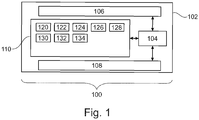
- Fig. 1 illustrates an example of a medical system 100.
- the medical system comprises a computer 102 with a processor 104.
- the processor is intended to represent one or more processors.
- the processors for example may be multiple cores. In other examples the processors 104 may be distributed between multiple computer systems and/or server units.
- the processor 104 is shown as being connected to an optional hardware interface 106.
- the hardware interface may for example be a network connection that enables the processor 104 to communicate with other computer systems and/or to communicate or control other components of the medical system 100.
- the processor in some examples may be useful for controlling a magnetic resonance imaging system.
- the processor 104 is also shown as being connected to an optional user interface 108.
- the processor 104 is shown as being further connected to a memory 110.
- the memory 110 may be any combination of memory which is accessible to the processor 104. This may include such things as main memory, cached memory, and also non-volatile memory such as flash RAM, hard drives, or other storage devices. In some examples the memory 110 may be considered to be a non-transitory computer-readable medium.
- the memory stores machine-executable instructions 120.
- the machine-executable instructions 120 enable the processor 104 to perform various data and image manipulation operations. In some examples the machine-executable instructions 120 also enable the processor 104 to control additional components via the hardware interface 106.
- the memory 110 is further shown as containing magnetic resonance imaging data 122 that has a spiral k-space sampling pattern.
- the magnetic resonance imaging data 122 may be received in various ways. It may for example be transferred to the memory 110 from another memory device or it may for example be received from a magnetic resonance imaging system or transferred via network connection.
- the memory 110 is further shown as containing at least one preliminary magnetic resonance image 124 that was reconstructed from the magnetic resonance imaging data 122.
- the memory 110 is further shown as containing at least one clinical image 126 that was calculated numerically from the at least one preliminary magnetic resonance image 124.
- the memory 110 is further shown as containing a first spatially dependent kernel 128 that was used to generate a first set of equations 130.
- the first set of equations 130 and the second set of equations 134 are solved numerically to obtain the at least one clinical image 126.
- Fig. 2 shows a flowchart which illustrates a method of operating the medical system 100 of Fig. 1 .
- the magnetic resonance imaging data 122 is received.
- the magnetic resonance imaging data has a spiral k-space sampling pattern.
- step 202 the at least one preliminary magnetic resonance image 124 is reconstructed from the magnetic resonance imaging data 122.
- the first set of equations 130 is constructed.
- the first set of equations comprise each of the at least one preliminary magnetic resonance image 124 being equal to an image transformation of at least one clinical image 126.
- the image transformation makes use of a first spatially dependent kernel 128 for each of the at least one clinical image 126.
- a second set of equations 134 is constructed.
- the second set of equations comprise at least one regularization matrix 132 times the at least one clinical image 126.
- the regularization matrix 132 may be the same for each clinical image 126. In other examples there may be an individual regularization matrix for each clinical image 126.
- the first set of equations 130 and the second set of equations 134 are solved simultaneously to numerically obtain the at least one clinical image 126.
- the regularization matrix 132 is constructed using a non-diagonal matrix.
- the construction of the second set of equations 134 would then be performed using the non-diagonal regularization matrix.
- This modification could for example be achieved by using a second spatially dependent kernel to construct the regularization matrix.
- the kernel may be used for measuring for example the local curvature and/or derivative within a particular location. This may be very useful for removing spatially dependent or repeating artifacts.
- the second spatially dependent kernel could be a Gaussian curvature kernel times a spatially dependent factor, a mean curvature kernel times spatially dependent factor, a Laplacian kernel times a spatially dependent factor, and a second derivative kernel time the spatially dependent factor.
- the spatially dependent factor may be useful in calculating how well the image is known at a particular location.
- the spatially dependent factor could be a spatially dependent signal-to-noise estimate, a spatially dependent estimate of a B0 magnetic field gradient, and a spatially dependent estimate of the B0 magnetic field error.
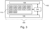
- Fig. 3 illustrates a further example of a medical system 300.
- the medical system 300 illustrated in Fig. 3 is similar to the medical system 100 illustrated in Fig. 1 .
- the medical system 300 has been specifically constructed or programmed to reconstruct images according to a Dixon magnetic resonance imaging protocol.
- the at least one clinical image 126 in this example is a Dixon water image 126' and a Dixon fat image 126".
- the at least one regularization matrix 132 is a separate water regularization matrix 132' for the Dixon water image 126' and a fat regularization matrix 132" for the Dixon fat image 126".
- the memory 110 is further shown as containing a water mask 320 and a fat mask 322.
- the water mask 320 is used to identify the location or partial volume of water in individual voxels of the Dixon water image 126'.
- the fat mask 122 is used to identify the location of fat or partial volume of fat within voxels of the Dixon fat image 126".
- the water mask 320 and the fat mask 322 could be obtained in different ways. For example, they could be obtained using a lower resolution scan. In some instances, previous magnetic resonance imaging images may be segmented and this information may be used for constructing a realistic water mask 320 and/or fat mask 322.
- the first set of equations 130 is a convolution of the Dixon water image 126' and a Dixon fat image 126" being equal to each of the at least one preliminary magnetic resonance image 124.
- the construction of the second set of equations is performed by multiplying the water regularization matrix times a matrix regularization of the Dixon water image 126'. This for example may be set equal zero or a constant.
- the second set of equations is further constructed by multiplying the fat regularization matrix 132" times the Dixon fat image 126". This again may for example be set equal to zero or a constant.
- the water mask 322 is multiplied by the water regularization matrix 132' and the fat mask 322 is multiplied by the fat regularization matrix 132".
- the water mask 320 may have an element for each of the water regularization matrix 132'.
- the fat mask 322 may have an element for each of the fat regularization matrix 132". In this example the multiplication would then be the multiplication of corresponding elements.
- Fig. 4 shows a flowchart which illustrates a method of operating the medical system 300 of Fig. 3 .
- steps 200, 202, and 204 are performed in an analogous way using the medical system 300 of Fig. 3 .
- step 400 the water regularization matrix 132' is multiplied by the water mask 320 before constructing the second set of equations.
- step 402 the fat regularization matrix 132" is multiplied times the fat mask 322 before constructing the second set of equations.
- the method then performs steps 206 and 208 which are analogous to steps 206 and 208 in the method of Fig. 2 .
- Fig. 5 illustrates a further example of a medical system 500.
- the medical system 500 in Fig. 5 is similar to the medical system 100 in Fig. 1 except that the medical system additionally comprises a magnetic resonance imaging system 502.
- the magnetic resonance imaging system 502 comprises a magnet 504.
- the magnet 504 is a superconducting cylindrical type magnet with a bore 506 through it.
- the use of different types of magnets is also possible; for instance it is also possible to use both a split cylindrical magnet and a so called open magnet.
- a split cylindrical magnet is similar to a standard cylindrical magnet, except that the cryostat has been split into two sections to allow access to the iso-plane of the magnet, such magnets may for instance be used in conjunction with charged particle beam therapy.
- An open magnet has two magnet sections, one above the other with a space in-between that is large enough to receive a subject: the arrangement of the two sections area similar to that of a Helmholtz coil. Open magnets are popular, because the subject is less confined. Inside the cryostat of the cylindrical magnet there is a collection of superconducting coils.
- an imaging zone 508 where the magnetic field is strong and uniform enough to perform magnetic resonance imaging.
- a field of view 509 is shown within the imaging zone 508.
- the magnetic resonance data that is acquired typically acquried for the field of view 509.
- a subject 518 is shown as being supported by a subject support 520 such that at least a portion of the subject 518 is within the imaging zone 508 and the field of view 509.
- the magnetic field gradient coils 510 are used for acquisition of preliminary magnetic resonance data to spatially encode magnetic spins within the imaging zone 508 of the magnet 504.
- the magnetic field gradient coils 510 connected to a magnetic field gradient coil power supply 512.
- the magnetic field gradient coils 510 are intended to be representative.
- magnetic field gradient coils 510 contain three separate sets of coils for spatially encoding in three orthogonal spatial directions.
- a magnetic field gradient power supply supplies current to the magnetic field gradient coils.
- the current supplied to the magnetic field gradient coils 510 is controlled as a function of time and may be ramped or pulsed.
- a radio-frequency coil 514 Adjacent to the imaging zone 508 is a radio-frequency coil 514 for manipulating the orientations of magnetic spins within the imaging zone 508 and for receiving radio transmissions from spins also within the imaging zone 508.
- the radio frequency antenna may contain multiple coil elements.
- the radio frequency antenna may also be referred to as a channel or antenna.
- the radio-frequency coil 514 is connected to a radio frequency transceiver 516.
- the radio-frequency coil 514 and radio frequency transceiver 516 may be replaced by separate transmit and receive coils and a separate transmitter and receiver. It is understood that the radio-frequency coil 514 and the radio frequency transceiver 516 are representative.
- the radio-frequency coil 514 is intended to also represent a dedicated transmit antenna and a dedicated receive antenna.
- the transceiver 516 may also represent a separate transmitter and receivers.
- the radio-frequency coil 514 may also have multiple receive/transmit elements and the radio frequency transceiver 516 may have multiple receive/transmit channels. For example if a parallel imaging technique such as SENSE is performed, the radio-frequency could 514 will have multiple coil elements.
- the transceiver 516 and the gradient controller 512 are shown as being connected to the hardware interface 106 of a computer system 102.
- the memory 110 is further shown as containing pulse sequence commands.
- the pulse sequence commands 530 are commands or data which may be translated into such commands which control the magnetic resonance imaging system 502 to acquire magnetic resonance imaging data according to a Dixon magnetic resonance imaging protocol.
- the memory 110 is shown as additionally comprising a set of pulse sequence commands 530.
- the pulse sequence commands 530 enable the processor 104 to control the magnetic resonance imaging system 502 to acquire the magnetic resonance imaging data 122 with a spiral k-space sampling pattern.
- the features of the medical system 500 in Fig. 5 may also be freely combined with the features of the medical system 300 of Fig. 3 . That is to say the pulse sequence commands 530 may be used to acquire the magnetic resonance imaging data 122 according to a Dixon magnetic resonance imaging protocol.
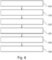
- Fig. 6 shows a method of operating the medical system 500 of Fig. 5 .
- the method in Fig. 6 is similar to the method illustrated in Fig. 2 .
- the method in Fig. 6 starts with step 600.
- the processor 104 controls the magnetic resonance imaging system with the pulse sequence commands 530 to acquire the magnetic resonance imaging data 122.
- the method proceeds to steps 200, 202, 204, 206, and 208 as is illustrated in Fig. 2 .
- a regularization step within the 'deblurring' step can be beneficial for image quality.
- Examples may implement this regularization as a high-pass filtering; that may be spatially dependent.
- the regularization level (or its exact shape) may depend on the gradient of the estimated field-deviation in that position.
- Examples may relate to the reconstruction of spiral scans (using a spiral k-space sampling pattern). In particular, it may provide an improvement upon what is known as "deblurring" - correcting for blurring that occurred due to an offset of the magnetic field (using the B0 magnetic field gradient and/or error), whereby the field at that location may be assumed to be known.
- Examples may have the benefit that the prevention of over-enhancement of high-spatial frequencies.
- this is prevented by "stopping to iterate the numerical solution before it gets too bad", which is a pretty inexact solution to the problem.
- the deblurring may be performed by applying a regularization (constructing 206 a second set of equations) that consists of a high-pass filtering; more specifically, the regularization may comprise of a position-dependent high-pass filtering; preferably, the regularization level (or its exact shape) depend on the gradient of the estimated field-deviation in that position.
- a regularization constructing 206 a second set of equations
- the regularization may comprise of a position-dependent high-pass filtering; preferably, the regularization level (or its exact shape) depend on the gradient of the estimated field-deviation in that position.
- a process of image reconstruction is as follows: as input the (complex) data from the three aforementioned echoes, which will be called ⁇ b 1 ,..., ⁇ bi , ..., ⁇ bE .
- the tilde symbol ( ⁇ ) indicates the presence of blurring.
- the Fourier transform of these images (the preliminary magentic resonance images 124) is denoted as K Ti ( u,v ) .
- the unknown fat image (Dixon fat image 126") is called I F ( m, n ) .
- t ( u, v ) as "the time at which the k-space sample ( u, v ) is acquired, relative to the first sample of the spiral-readout" ( t ( u, v ) is assumed to have the same shape for all echoes); read TE i as "the difference of the time-point of the first sample of echo i , relative to the spin-echo time point of the sequence"; and read ⁇ f F as "the difference in frequency between fat and water-protons" (a somewhat simplified formula, since fat actually has more than one spectral component, but one dominates).
- I ⁇ bi C Wi I W + C Fi I F , which can be read as follows: I W and I F are column-vectors, each element corresponding to one pixel location; C Wi and C Fi are matrices (number-of-pixels x number-of-pixels) representing the position-dependent 'blurring' kernels.
- I ⁇ bi C Wi C Fi I W I F .
- I ⁇ b C I W I F . This is an example of the first set of equations 130.
- the solution consists of iteratively resolving I W and I F from the knowledge of C and ⁇ b , e.g. by using, for example, steepest descent of conjugate-gradients.
- Q W and Q F are water 132' and fat 132" regularization matricies respectively and are used to form the second set of equations 134.
- each row of (e.g.) Q W indicates which combination of pixels from I W is supposed to be zero.
- Fig. 7 illustrates several spiral k-space sampling patterns 700, 702.
- a spiral k-space sampling pattern 700 is represented.
- the spiral k-space sampling pattern 702 is shown as being distorted due to a high gradient of the B 0 magnetic field.
- the area marked 704 is intended to be sampled but is not able to be because of distortions of the sampling pattern 702.
- the reconstruction algorithm attempts to reconstruct meaningful data corresponding to the spatial frequencies within the circle. It simply does not have enough information to meaningfully reconstruct the information corresponding to the area 704 in plot 702.
- the regularization matrices 132, 132', 132" may be constructed using kernels. This is illustrated in the examples below using a 1-dimesnional "image.” This simplifies the explanation and the and extension to two dimensional matricies is straightforward.
- Multiplying an image with a scalar a can also be seen by multiplying the vector with a diagonal matrix, i.e.: a 0 0 0 0 0 0 0 a 0 0 0 0 0 0 a 0 0 0 0 0 0 0 a 0 0 0 0 0 0 0 a 0 0 0 0 0 0 0 0 0 0 a 0 0 0 0 0 0 0 0 0 0 a a 0 0 0 0 0 0 0 0 0 a a
- a convolution with a fixed kernel (e.g. a 3-points kernel [ a b c ]) can also be written as a matrix multiplication, the matrix being: b c 0 0 0 0 0 a b c 0 0 0 0 a b c 0 0 0 0 a b c 0 0 0 0 a b c 0 0 0 0 0 0 a b c 0 0 0 0 0 a b c 0 0 0 0 a b
- a matrix like C W 1 could for example look approximatly like this: 1 0 0 0 0 0 0 0.1 0.8 0.1 0 0 0 0.1 0.2 0.4 0.2 0.1 0 0 -0.2 0.8 -0.2 0.8 -0.2 0 0 -0.2 0.8 -0.2 0.8 0 0 0 0.1 0.8
- the blurring kernel is represented by a single peak ([0 0 0 1 0 0 0]); further down the 'image' (in this example the 4 th pixel) the field substantially deviates, which causes a blurring represented by the kernel [0 0 -0.2 0.8 -0.2 0.8 -0.2 0 0].
- the regularization matrix Q can also be seen as a matrix as well as a convolution with spatially-dependent kernels.
- a simplified form is to fill each row of Q by a two-dimensional 2nd-derivative kernel. For example:
- Examples may also provide for better Dixon imaging by using prior knowledge.
- a benefit of some examples may be the improved problem conditioning for spiral reconstruction leading to faster convergence and improved image quality (through better water/fat separation). Both elements may be beneficial to the overall success in removing or reducing artifacts in magnetic resonance imaging that uses spiral k-space sampling.
- Some exmaples may use species dependent regularization.
- I W I F C H C + Q W H Q W 0 0 Q F H Q F ⁇ 1 C H I ⁇ b
- Balancing of the regularization with the data 'consistency' term can be done similar to how it is done in SENSE.
- a computer program may be stored/distributed on a suitable medium, such as an optical storage medium or a solid-state medium supplied together with or as part of other hardware, but may also be distributed in other forms, such as via the Internet or other wired or wireless telecommunication systems. Any reference signs in the claims should not be construed as limiting the scope.
Landscapes
- Physics & Mathematics (AREA)
- Health & Medical Sciences (AREA)
- Engineering & Computer Science (AREA)
- General Physics & Mathematics (AREA)
- High Energy & Nuclear Physics (AREA)
- Condensed Matter Physics & Semiconductors (AREA)
- General Health & Medical Sciences (AREA)
- Nuclear Medicine, Radiotherapy & Molecular Imaging (AREA)
- Radiology & Medical Imaging (AREA)
- Signal Processing (AREA)
- Life Sciences & Earth Sciences (AREA)
- Computer Vision & Pattern Recognition (AREA)
- Artificial Intelligence (AREA)
- Molecular Biology (AREA)
- Medical Informatics (AREA)
- Heart & Thoracic Surgery (AREA)
- Surgery (AREA)
- Animal Behavior & Ethology (AREA)
- Public Health (AREA)
- Veterinary Medicine (AREA)
- Biomedical Technology (AREA)
- Pathology (AREA)
- Biophysics (AREA)
- Theoretical Computer Science (AREA)
- Magnetic Resonance Imaging Apparatus (AREA)
- Geometry (AREA)
Priority Applications (6)
| Application Number | Priority Date | Filing Date | Title |
|---|---|---|---|
| EP19179993.1A EP3751300A1 (en) | 2019-06-13 | 2019-06-13 | Reconstruction of spiral k-space sampled magnetic resonance images |
| US17/617,957 US11852708B2 (en) | 2019-06-13 | 2020-06-11 | Reconstruction of spiral k-space sampled magnetic resonance images |
| DE112020002805.4T DE112020002805T5 (de) | 2019-06-13 | 2020-06-11 | Rekonstruktion von spiralförmigen k-raum-abgetasteten magnetresonanzbildern |
| CN202080043157.6A CN113966471B (zh) | 2019-06-13 | 2020-06-11 | 螺旋k空间采样磁共振图像的重建 |
| JP2021572861A JP7558981B2 (ja) | 2019-06-13 | 2020-06-11 | スパイラルk空間サンプリングされた磁気共鳴画像の再構成 |
| PCT/EP2020/066239 WO2020249696A1 (en) | 2019-06-13 | 2020-06-11 | Reconstruction of spiral k-space sampled magnetic resonance images |
Applications Claiming Priority (1)
| Application Number | Priority Date | Filing Date | Title |
|---|---|---|---|
| EP19179993.1A EP3751300A1 (en) | 2019-06-13 | 2019-06-13 | Reconstruction of spiral k-space sampled magnetic resonance images |
Publications (1)
| Publication Number | Publication Date |
|---|---|
| EP3751300A1 true EP3751300A1 (en) | 2020-12-16 |
Family
ID=66857781
Family Applications (1)
| Application Number | Title | Priority Date | Filing Date |
|---|---|---|---|
| EP19179993.1A Withdrawn EP3751300A1 (en) | 2019-06-13 | 2019-06-13 | Reconstruction of spiral k-space sampled magnetic resonance images |
Country Status (6)
| Country | Link |
|---|---|
| US (1) | US11852708B2 (https=) |
| EP (1) | EP3751300A1 (https=) |
| JP (1) | JP7558981B2 (https=) |
| CN (1) | CN113966471B (https=) |
| DE (1) | DE112020002805T5 (https=) |
| WO (1) | WO2020249696A1 (https=) |
Cited By (1)
| Publication number | Priority date | Publication date | Assignee | Title |
|---|---|---|---|---|
| CN121169946A (zh) * | 2025-10-10 | 2025-12-19 | 中国人民解放军总医院第七医学中心 | 一种基于核磁共振影像的临床病灶辅助分割系统 |
Families Citing this family (3)
| Publication number | Priority date | Publication date | Assignee | Title |
|---|---|---|---|---|
| EP3543724A1 (en) * | 2018-03-20 | 2019-09-25 | Koninklijke Philips N.V. | (3-n)-dimensional determination of electric conductivity |
| CN113827001B (zh) * | 2021-08-26 | 2022-09-06 | 东南大学 | 基于电涡流传感器阵列的布莱叶盲文阅读手环 |
| CN116012472A (zh) * | 2022-12-02 | 2023-04-25 | 中国科学院深圳先进技术研究院 | 一种快速磁共振成像方法及装置 |
Family Cites Families (12)
| Publication number | Priority date | Publication date | Assignee | Title |
|---|---|---|---|---|
| US7545966B2 (en) | 2003-05-05 | 2009-06-09 | Case Western Reserve University | Efficient methods for reconstruction and deblurring of magnetic resonance images |
| DE102006032339B3 (de) | 2006-07-12 | 2007-11-29 | Siemens Ag | Verfahren und Gerät zur beschleunigten Spiral-kodierten Bildgebung in der Magnetresonanztomographie |
| JP4742192B2 (ja) * | 2009-04-28 | 2011-08-10 | Necソフト株式会社 | 年齢推定装置及び方法並びにプログラム |
| JP5717839B2 (ja) * | 2010-03-23 | 2015-05-13 | マックス プランク ゲゼルシャフト ツゥアー フェデルゥン デル ヴィッセンシャフテン エー フォー | 正規化非線形逆再構成法を用いて磁気共鳴画像シーケンスを再構成するための方法及び装置 |
| CN102232830B (zh) * | 2010-04-30 | 2014-09-03 | 西门子(深圳)磁共振有限公司 | 一种磁共振成像水脂分离方法 |
| US10564241B2 (en) * | 2012-01-17 | 2020-02-18 | Regents Of The University Of Minnesota | Steering resonance along a trajectory |
| US9322896B2 (en) | 2012-04-20 | 2016-04-26 | University Of Virginia Patent Foundation | Systems and methods for reduced off-resonance blurring in spiral imaging |
| US10646165B2 (en) * | 2013-04-10 | 2020-05-12 | The General Hospital Corporation | Removing eletrophysicologic artifacts from a magnetic resonance imaging system |
| CN105308469B (zh) * | 2013-06-06 | 2019-11-12 | 皇家飞利浦有限公司 | 一种mr成像方法、mr设备以及相关数据载体 |
| US10746831B2 (en) * | 2014-10-21 | 2020-08-18 | Dignity Health | System and method for convolution operations for data estimation from covariance in magnetic resonance imaging |
| US10591562B2 (en) * | 2015-06-12 | 2020-03-17 | Koninklijke Philips N.V. | Bone MRI using B0 inhomogeneity map and a subject magnetic susceptibility map |
| CN106680748B (zh) * | 2016-12-30 | 2019-10-08 | 上海联影医疗科技有限公司 | 磁共振图像获取方法及磁共振系统 |
-
2019
- 2019-06-13 EP EP19179993.1A patent/EP3751300A1/en not_active Withdrawn
-
2020
- 2020-06-11 JP JP2021572861A patent/JP7558981B2/ja active Active
- 2020-06-11 WO PCT/EP2020/066239 patent/WO2020249696A1/en not_active Ceased
- 2020-06-11 US US17/617,957 patent/US11852708B2/en active Active
- 2020-06-11 DE DE112020002805.4T patent/DE112020002805T5/de active Pending
- 2020-06-11 CN CN202080043157.6A patent/CN113966471B/zh active Active
Non-Patent Citations (2)
| Title |
|---|
| MICHAEL LUSTIG ET AL: "SPIRiT: Iterative self-consistent parallel imaging reconstruction from arbitrary k-space", MAGNETIC RESONANCE IN MEDICINE, 1 June 2010 (2010-06-01), pages n/a - n/a, XP055007508, ISSN: 0740-3194, DOI: 10.1002/mrm.22428 * |
| TRUONG: "Application of k-Space Energy Spectrum Analysis for Inherent and Dynamic BO Mapping and Deblurring in Spiral Imaging", MAG. RES. MED., vol. 64, 2010, pages 1121 - 1127 |
Cited By (1)
| Publication number | Priority date | Publication date | Assignee | Title |
|---|---|---|---|---|
| CN121169946A (zh) * | 2025-10-10 | 2025-12-19 | 中国人民解放军总医院第七医学中心 | 一种基于核磁共振影像的临床病灶辅助分割系统 |
Also Published As
| Publication number | Publication date |
|---|---|
| WO2020249696A1 (en) | 2020-12-17 |
| DE112020002805T5 (de) | 2022-04-21 |
| CN113966471A (zh) | 2022-01-21 |
| JP7558981B2 (ja) | 2024-10-01 |
| US11852708B2 (en) | 2023-12-26 |
| JP2022536638A (ja) | 2022-08-18 |
| US20220244335A1 (en) | 2022-08-04 |
| CN113966471B (zh) | 2025-05-09 |
Similar Documents
| Publication | Publication Date | Title |
|---|---|---|
| US11852708B2 (en) | Reconstruction of spiral k-space sampled magnetic resonance images | |
| CN111263896B (zh) | 在磁共振成像系统中对相位相关的伪影的数据驱动的校正 | |
| EP3602096B1 (en) | Sub voxel resolution magnetic resonance fingerprinting imaging | |
| EP3123191B1 (en) | Propeller magnetic resonance imaging | |
| US10955508B2 (en) | BO-corrected sensitivity encoding magnetic resonance imaging | |
| US20160146918A1 (en) | Corrected magnetic resonance imaging using coil sensitivities | |
| EP3542176A1 (en) | Intensity corrected magnetic resonance images | |
| EP3931587B1 (en) | Calculation of a b0 image using multiple diffusion weighted mr images | |
| US11686800B2 (en) | Correction of magnetic resonance images using simulated magnetic resonance images | |
| EP4321891A1 (en) | Two-stage denoising for magnetic resonance imaging | |
| EP4653904A1 (en) | Removal of free induction decay artifacts in turbo spin echo mri images | |
| JP7542633B2 (ja) | 勾配エコー磁気共鳴画像の反復的再構成 | |
| EP4306980A1 (en) | Determiniaton of b0 inhomogeneity in magnetic resonance imaging | |
| US20250347762A1 (en) | Determination of bo inhomogenity in magnetic resonance imaging |
Legal Events
| Date | Code | Title | Description |
|---|---|---|---|
| PUAI | Public reference made under article 153(3) epc to a published international application that has entered the european phase |
Free format text: ORIGINAL CODE: 0009012 |
|
| STAA | Information on the status of an ep patent application or granted ep patent |
Free format text: STATUS: THE APPLICATION HAS BEEN PUBLISHED |
|
| AK | Designated contracting states |
Kind code of ref document: A1 Designated state(s): AL AT BE BG CH CY CZ DE DK EE ES FI FR GB GR HR HU IE IS IT LI LT LU LV MC MK MT NL NO PL PT RO RS SE SI SK SM TR |
|
| AX | Request for extension of the european patent |
Extension state: BA ME |
|
| STAA | Information on the status of an ep patent application or granted ep patent |
Free format text: STATUS: THE APPLICATION IS DEEMED TO BE WITHDRAWN |
|
| 18D | Application deemed to be withdrawn |
Effective date: 20210617 |