EP3751247B1 - Kraftsensor und elektrophysiologischer katheter - Google Patents
Kraftsensor und elektrophysiologischer katheter Download PDFInfo
- Publication number
- EP3751247B1 EP3751247B1 EP19751623.0A EP19751623A EP3751247B1 EP 3751247 B1 EP3751247 B1 EP 3751247B1 EP 19751623 A EP19751623 A EP 19751623A EP 3751247 B1 EP3751247 B1 EP 3751247B1
- Authority
- EP
- European Patent Office
- Prior art keywords
- limiting
- limiting portion
- force sensor
- elastic tube
- transverse slot
- Prior art date
- Legal status (The legal status is an assumption and is not a legal conclusion. Google has not performed a legal analysis and makes no representation as to the accuracy of the status listed.)
- Active
Links
Images





Classifications
-
- G—PHYSICS
- G01—MEASURING; TESTING
- G01L—MEASURING FORCE, STRESS, TORQUE, WORK, MECHANICAL POWER, MECHANICAL EFFICIENCY, OR FLUID PRESSURE
- G01L1/00—Measuring force or stress, in general
- G01L1/20—Measuring force or stress, in general by measuring variations in ohmic resistance of solid materials or of electrically-conductive fluids; by making use of electrokinetic cells, i.e. liquid-containing cells wherein an electrical potential is produced or varied upon the application of stress
- G01L1/22—Measuring force or stress, in general by measuring variations in ohmic resistance of solid materials or of electrically-conductive fluids; by making use of electrokinetic cells, i.e. liquid-containing cells wherein an electrical potential is produced or varied upon the application of stress using resistance strain gauges
-
- A—HUMAN NECESSITIES
- A61—MEDICAL OR VETERINARY SCIENCE; HYGIENE
- A61B—DIAGNOSIS; SURGERY; IDENTIFICATION
- A61B18/00—Surgical instruments, devices or methods for transferring non-mechanical forms of energy to or from the body
-
- A—HUMAN NECESSITIES
- A61—MEDICAL OR VETERINARY SCIENCE; HYGIENE
- A61B—DIAGNOSIS; SURGERY; IDENTIFICATION
- A61B18/00—Surgical instruments, devices or methods for transferring non-mechanical forms of energy to or from the body
- A61B18/04—Surgical instruments, devices or methods for transferring non-mechanical forms of energy to or from the body by heating
- A61B18/12—Surgical instruments, devices or methods for transferring non-mechanical forms of energy to or from the body by heating by passing a current through the tissue to be heated, e.g. high-frequency current
-
- A—HUMAN NECESSITIES
- A61—MEDICAL OR VETERINARY SCIENCE; HYGIENE
- A61B—DIAGNOSIS; SURGERY; IDENTIFICATION
- A61B18/00—Surgical instruments, devices or methods for transferring non-mechanical forms of energy to or from the body
- A61B18/04—Surgical instruments, devices or methods for transferring non-mechanical forms of energy to or from the body by heating
- A61B18/12—Surgical instruments, devices or methods for transferring non-mechanical forms of energy to or from the body by heating by passing a current through the tissue to be heated, e.g. high-frequency current
- A61B18/14—Probes or electrodes therefor
- A61B18/1492—Probes or electrodes therefor having a flexible, catheter-like structure, e.g. for heart ablation
-
- A—HUMAN NECESSITIES
- A61—MEDICAL OR VETERINARY SCIENCE; HYGIENE
- A61B—DIAGNOSIS; SURGERY; IDENTIFICATION
- A61B5/00—Measuring for diagnostic purposes; Identification of persons
- A61B5/02—Detecting, measuring or recording for evaluating the cardiovascular system, e.g. pulse, heart rate, blood pressure or blood flow
- A61B5/021—Measuring pressure in heart or blood vessels
- A61B5/0215—Measuring pressure in heart or blood vessels by means inserted into the body
-
- A—HUMAN NECESSITIES
- A61—MEDICAL OR VETERINARY SCIENCE; HYGIENE
- A61B—DIAGNOSIS; SURGERY; IDENTIFICATION
- A61B5/00—Measuring for diagnostic purposes; Identification of persons
- A61B5/68—Arrangements of detecting, measuring or recording means, e.g. sensors, in relation to patient
- A61B5/6846—Arrangements of detecting, measuring or recording means, e.g. sensors, in relation to patient specially adapted to be brought in contact with an internal body part, i.e. invasive
- A61B5/6847—Arrangements of detecting, measuring or recording means, e.g. sensors, in relation to patient specially adapted to be brought in contact with an internal body part, i.e. invasive mounted on an invasive device
- A61B5/6852—Catheters
-
- G—PHYSICS
- G01—MEASURING; TESTING
- G01L—MEASURING FORCE, STRESS, TORQUE, WORK, MECHANICAL POWER, MECHANICAL EFFICIENCY, OR FLUID PRESSURE
- G01L1/00—Measuring force or stress, in general
- G01L1/04—Measuring force or stress, in general by measuring elastic deformation of gauges, e.g. of springs
-
- A—HUMAN NECESSITIES
- A61—MEDICAL OR VETERINARY SCIENCE; HYGIENE
- A61B—DIAGNOSIS; SURGERY; IDENTIFICATION
- A61B18/00—Surgical instruments, devices or methods for transferring non-mechanical forms of energy to or from the body
- A61B2018/00315—Surgical instruments, devices or methods for transferring non-mechanical forms of energy to or from the body for treatment of particular body parts
- A61B2018/00345—Vascular system
-
- A—HUMAN NECESSITIES
- A61—MEDICAL OR VETERINARY SCIENCE; HYGIENE
- A61B—DIAGNOSIS; SURGERY; IDENTIFICATION
- A61B18/00—Surgical instruments, devices or methods for transferring non-mechanical forms of energy to or from the body
- A61B2018/00315—Surgical instruments, devices or methods for transferring non-mechanical forms of energy to or from the body for treatment of particular body parts
- A61B2018/00345—Vascular system
- A61B2018/00351—Heart
-
- A—HUMAN NECESSITIES
- A61—MEDICAL OR VETERINARY SCIENCE; HYGIENE
- A61B—DIAGNOSIS; SURGERY; IDENTIFICATION
- A61B18/00—Surgical instruments, devices or methods for transferring non-mechanical forms of energy to or from the body
- A61B2018/00315—Surgical instruments, devices or methods for transferring non-mechanical forms of energy to or from the body for treatment of particular body parts
- A61B2018/00345—Vascular system
- A61B2018/00404—Blood vessels other than those in or around the heart
-
- A—HUMAN NECESSITIES
- A61—MEDICAL OR VETERINARY SCIENCE; HYGIENE
- A61B—DIAGNOSIS; SURGERY; IDENTIFICATION
- A61B18/00—Surgical instruments, devices or methods for transferring non-mechanical forms of energy to or from the body
- A61B2018/00315—Surgical instruments, devices or methods for transferring non-mechanical forms of energy to or from the body for treatment of particular body parts
- A61B2018/00434—Neural system
-
- A—HUMAN NECESSITIES
- A61—MEDICAL OR VETERINARY SCIENCE; HYGIENE
- A61B—DIAGNOSIS; SURGERY; IDENTIFICATION
- A61B18/00—Surgical instruments, devices or methods for transferring non-mechanical forms of energy to or from the body
- A61B2018/00571—Surgical instruments, devices or methods for transferring non-mechanical forms of energy to or from the body for achieving a particular surgical effect
- A61B2018/00577—Ablation
-
- A—HUMAN NECESSITIES
- A61—MEDICAL OR VETERINARY SCIENCE; HYGIENE
- A61B—DIAGNOSIS; SURGERY; IDENTIFICATION
- A61B18/00—Surgical instruments, devices or methods for transferring non-mechanical forms of energy to or from the body
- A61B2018/00636—Sensing and controlling the application of energy
- A61B2018/00773—Sensed parameters
-
- A—HUMAN NECESSITIES
- A61—MEDICAL OR VETERINARY SCIENCE; HYGIENE
- A61B—DIAGNOSIS; SURGERY; IDENTIFICATION
- A61B18/00—Surgical instruments, devices or methods for transferring non-mechanical forms of energy to or from the body
- A61B2018/00636—Sensing and controlling the application of energy
- A61B2018/00904—Automatic detection of target tissue
-
- A—HUMAN NECESSITIES
- A61—MEDICAL OR VETERINARY SCIENCE; HYGIENE
- A61B—DIAGNOSIS; SURGERY; IDENTIFICATION
- A61B90/00—Instruments, implements or accessories specially adapted for surgery or diagnosis and not covered by any of the groups A61B1/00 - A61B50/00, e.g. for luxation treatment or for protecting wound edges
- A61B90/06—Measuring instruments not otherwise provided for
- A61B2090/064—Measuring instruments not otherwise provided for for measuring force, pressure or mechanical tension
- A61B2090/065—Measuring instruments not otherwise provided for for measuring force, pressure or mechanical tension for measuring contact or contact pressure
-
- A—HUMAN NECESSITIES
- A61—MEDICAL OR VETERINARY SCIENCE; HYGIENE
- A61B—DIAGNOSIS; SURGERY; IDENTIFICATION
- A61B2562/00—Details of sensors; Constructional details of sensor housings or probes; Accessories for sensors
- A61B2562/02—Details of sensors specially adapted for in-vivo measurements
- A61B2562/0247—Pressure sensors
-
- A—HUMAN NECESSITIES
- A61—MEDICAL OR VETERINARY SCIENCE; HYGIENE
- A61B—DIAGNOSIS; SURGERY; IDENTIFICATION
- A61B2562/00—Details of sensors; Constructional details of sensor housings or probes; Accessories for sensors
- A61B2562/02—Details of sensors specially adapted for in-vivo measurements
- A61B2562/0261—Strain gauges
-
- A—HUMAN NECESSITIES
- A61—MEDICAL OR VETERINARY SCIENCE; HYGIENE
- A61M—DEVICES FOR INTRODUCING MEDIA INTO, OR ONTO, THE BODY; DEVICES FOR TRANSDUCING BODY MEDIA OR FOR TAKING MEDIA FROM THE BODY; DEVICES FOR PRODUCING OR ENDING SLEEP OR STUPOR
- A61M2205/00—General characteristics of the apparatus
- A61M2205/33—Controlling, regulating or measuring
- A61M2205/332—Force measuring means
Definitions
- the present invention relates to the technical field of medical instruments and, more specifically, to a force sensor and an electrophysiology catheter.
- an ablation or mapping catheter may be introduced into the heart via a vein or artery to find an aberrant electrical signal position or pathway by endocardial mapping, and then apply energy at the position or pathway to ablate it to eliminate or alter undesirable electrical signals, thus achieving curative results.
- an ablation catheter may be arterially introduced into an artery connecting the abdominal aorta and the kidney to ablate and block the parasympathetic nerve pathway to lower the blood pressure.
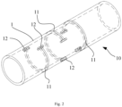
- Fig. 1 schematically illustrates a conventional electrophysiology catheter, with a force sensor, passing through an intracardiac guide sheath.
- a guide sheath 20 establishes a channel through which an electrophysiology catheter with a force sensor 10 can be delivered into the body to perform an associated interventional procedure.
- the electrophysiology catheter may be an ablation catheter, a mapping catheter or another type of electrophysiology catheter.
- the electrophysiology catheter includes a distal end at which the force sensor 10 is disposed.
- the force sensor 10 is configured to obtain the magnitude and direction of a contact force that occurs when the distal end of the catheter is brought into contact with the surface of a vessel wall or tissue.
- the force sensor 10 is configured to measure a reaction force in response to the contact force exerted by the catheter's distal end on the vessel wall or tissue.
- distinct guide sheaths 20 are designed with distal ends having different curved shapes. Additionally, such a guide sheath 20 should be constructed to be relatively stiff in order to maintain the designed curved shape while ensuring that a respective electrophysiology catheter can reach the target site. Consequently, as the electrophysiology catheter is guided through the guide sheath 20, the force sensor 10 tends to experience a great deformation under the action of significant forces exerted by the guide sheath 20.
- the force sensor 10 This requires the force sensor 10 to be able to withstand large bending loads. Otherwise, when impacted by a large force, the force sensor 10 may break, leading to failure or a shortened service life of a strain gauge therein due to a load exceeding its measuring range.
- the conventional force sensor 10 may include an elastic tube 1 having a wall in which one or more pierced transverse slots 11 (i.e., slots formed by cutting though the wall of the elastic tube 1) are formed in order to enhance elasticity of the elastic tube 1 (especially a metal tube) and amplify any deformation thereof under the action of the transverse slots 11.
- a strain gauge on the elastic tube 1 may then sense the amplified deformation and outputs an electrical signal indicating the change.
- multiple such transverse slots 11 are formed along different circumferential circles and spaced from one another circumferentially in a staggered manner. That is, orthographic projections of these transverse slots 11 on a single plane are preferably distributed in a circumferentially staggered pattern.
- Each transverse slot 11 is an arc-shaped slot cut along a circumference of the wall of the elastic tube 1 and provided at its both opposing ends each with a longitudinal slot 12 for mitigating stress concentration at the opposing ends of the transverse slot 11 and thus increasing its tensile strength.
- the transverse slot 11 when the elastic tube 1 is stretched, the transverse slot 11 will axially deform at its both axial sides away from the initial positions indicated by dashed lines in the figure, which will still cause the issue of "stress concentration" at the opposing ends.
- the transverse slot 11 may crack, or even break, at the opposing ends, leading to permanent failure of the strain gauge due to the excessive strain load exceeding its maximum measuring range.
- CN 106 264 719 A discloses an electrophysiological catheter including distal end of catheter provided with pressure transducer including elastic body and foil gauge.
- CN 107 496 055 A discloses a heart valve delivery catheter including outer tube assembly and an inner tube component arranged in the outer tube assembly.
- It is an objective of the present invention is to provide a force sensor and an electrophysiology catheter.
- the force sensor can be effectively avoided from experiencing any significant impact when the electrophysiology catheter is guided through a sheath. In this way, it is maintained within a predetermined deformation range that prevents breakage of an elastic tube of the sensor and enables an extended service life of any strain gauge therein.
- the present invention provides a force sensor as defined in claim 1.
- the force sensor further comprises at least one second limiting structure disposed between the opposing ends of the transverse slot, each of the at least one second limiting structure comprising a third limiting portion connected to the first wall and a fourth limiting portion connected to the second wall, and when the transverse slot deforms axially, the third limiting portion and fourth limiting portion are able to responsively move relative to each other until being engaged with each other.
- the third limiting portion is a male portion with a third external surface and the fourth limiting portion is a female portion with a fourth external surface, the third external surface and the forth external surface being arranged opposite to each other and defining a clearance between the third external surface and the forth external surface, and wherein the third limiting portion is confined within the fourth limiting portion.
- the first limiting portion, second limiting portion, third limiting portion and fourth limiting portion are of a same shape.
- the force sensor comprises a plurality of the first limiting structures, and wherein each of the at least one second limiting structure is disposed between adjacent two of the first limiting structures, the third limiting portion is a portion between adjacent two of the first limiting portions thereof and the fourth limiting portion is a gap between adjacent two of the second limiting portions.
- an external surface of the second limiting portion and an external surface of the third limiting portion are arranged axially opposite to each other and define a clearance between the external surface of the second limiting portion and the external surface of the third limiting portion.
- the second limiting portion comprises a second vertical portion and a second horizontal portion
- the third limiting portion comprises a third vertical portion and a third horizontal portion, the second vertical portion being connected to the second wall, the third vertical portion being connected to the first wall, the second and third horizontal portions together forming an engagement.
- the male portions are trapezoidal, L-shaped or T-shaped.
- the force sensor further comprises two longitudinal slots arranged at the respective opposing ends of the transverse slot.
- the transverse slot extends in a curved shape on a circumferential surface of the elastic tube.
- the transverse slot is formed in the elastic tube by laser cutting.
- the force sensor comprises a plurality of the transverse slots and a plurality of the strain gauges, the transverse slots spaced apart from one another across the elastic tube in an axial direction of the elastic tube and staggered from one another along a circumferential direction of the elastic tube, each of the strain gauges disposed between two opposing ends of a respective one of the transverse slots.
- the force sensor includes an elastic tube and a strain gauge arranged on the elastic tube.
- a pierced transverse slot is formed in the elastic tube, and at least one first limiting structure is disposed between two opposing ends of the transverse slot.
- Each first limiting structure includes a first limiting portion connected to a wall of the transverse slot and a second limiting portion connected to the other wall of the transverse slot.
- the first and second limiting portions will simultaneously move relative to each other.
- the two limiting portions will engage with each other.
- the transverse slot is maintained within a predetermined deformation range that can avoid breakage of the elastic tube and result in a prolonged service life of the strain gauge.
- proximal and distal describe relative orientations, positions and directions between elements or actions, viewed by a physician operating the product.
- proximal end usually refers to an end of the product close to the physician during normal operation
- distal end usually refers to an end thereof that enters the patient first.
- Axial and “longitudinal” refer to an axial direction of an elastic tube
- circumferential and “transverse” refer to a circumferential direction thereof.
- each transverse slot 11 is maintained within a predetermined deformation range that ensures that the elastic tube 1 will not break.
- at least one first limiting structure is added between opposing ends of each transverse slot 11.
- the at least one first limiting structure In response to an axial deformation of the transverse slot 11, a relative movement will occur in the at least one first limiting structure, and when reaching a limit position, an engagement will occur, defining a maximum deformation amount of the transverse slot 11.
- a relative movement will occur in the at least one first limiting structure, and when reaching a limit position, an engagement will occur, defining a maximum deformation amount of the transverse slot 11.
- the elastic tube 1 can be maintained within a predetermined deformation range that prevents breakage of the elastic tube and enables an extended service life of a strain gauge.
- a strain gauge provides a strain measurement range of ⁇ 20,000 microstrains.
- the at least one first limiting structure is generally configured to limit the maximum deformation amount to be not over 20,000 microstrains.
- each first limiting structure may include a first limiting portion and a second limiting portion.
- the first limiting portion is connected to a first wall of the transverse slot 11.
- the first limiting portion Upon any axial deformation of the first wall, the first limiting portion will experience a synchronous axial displacement.
- the second limiting portion is connected to a second wall of the transverse slot 11. Similarly, when the second wall deforms axially, a synchronous axial displacement will responsively occur to the second limiting portion.
- the first wall opposes the second wall along a widthwise direction of the transverse slot 11.
- both the first and second walls will deform accordingly, driving the first and second limiting portions to move relative to (i.e., toward or away from) each other.
- a predefined threshold e.g. 500 g
- the relative movement of the first and second limiting portions will be accommodated in a preset clearance without resulting in a contact therebetween.
- the first and second limiting portions will move toward or away from each other until the limit position is reached, where they cooperate to form a snap-fit engagement that prevents any of them from further moving.
- the transverse slot 11 deforms by a maximum allowable amount under the action of the snap-fit engagement of the first and second limiting portions.
- the maximum deformation amount of the transverse slot 11 in order to control the maximum deformation amount of the transverse slot 11, an axial clearance between the first and second limiting portions is necessary for allowing an axial relative movement between the two limiting portions while ensuring a space for compressive or tensile deformation of the elastic tube 1. Therefore, the maximum deformation amount can be controlled, in general terms, below 20,000 microstrains by suitably setting a dimension of the clearance.
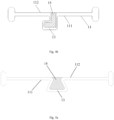
- a transverse slot 11 formed in an elastic tube 1 has a first wall 111 and a second wall 112, arranged along a widthwise direction of the slot.
- the widthwise direction is defined as an axial direction when a center axis of the transverse slot coincides with a center axis of the elastic tube.
- a first limiting portion 13 is arranged on the first wall 111, while a second limiting portion 14 is arranged on the second wall 112.
- the first and second limiting portions 13, 14 are both L-shaped portions that match each other in shape.
- the first limiting portion 13 is a female L-shaped portion with a first internal surface
- the second limiting portion 14 is a male L-shaped portion with a second external surface.
- the first internal surface and the second external surface oppose each other with a clearance therebetween.
- the second limiting portion 14 is able to move with the transverse slot 11 relative to (i.e., to approach or get away from) the first limiting portion 13 while being always confined within the first limiting portion 13 without dislodging therefrom.
- a transverse slot 11 formed in an elastic tube 1 also has a first wall 111 and a second wall 112.
- a first limiting portion 13 is arranged on the first wall 111, while a second limiting portion 14 is arranged on the second wall 112.
- the first limiting portion 13 is a trapezoidal male portion, while the second limiting portion 14 is a trapezoidal female portion.
- the trapezoidal male and female portions will move away from each other until a limit position is reached where a maximum cross-sectional width of the trapezoidal male portion is greater than a minimum cross-sectional width of the trapezoidal female portion (i.e., an opening width), bringing an external surface of the trapezoidal male portion into abutment with an internal surface of the trapezoidal female portion and thus resulting in a snap fit engagement therebetween.
- a maximum cross-sectional width of the trapezoidal male portion is greater than a minimum cross-sectional width of the trapezoidal female portion (i.e., an opening width)
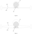
- a transverse slot 11 formed in an elastic tube 1 also has a first wall 111 and a second wall 112.
- a first limiting portion 13 is arranged on the first wall 111, while a second limiting portion 14 is arranged on the second wall 112.
- the first limiting portion 13 is a major arc-shaped female portion, while the second limiting portion 14 is a major arc-shaped male portion.
- the major arc-shaped male and female portions will move away from each other until a limit position is reached where an external surface of the major arc-shaped male portion is brought into close abutment with an internal surface of the major arc-shaped female portion, resulting in a snap fit engagement therebetween, because the major arc-shaped male portion has at least one portion having a cross-sectional width that is greater than an opening width of the major arc-shaped female portion.
- Fig. 6d shows another example not belonging to the invention that is similar to the one previously introduced, except that a plurality of first limiting structures are arranged on opposing ends of a transverse slot 11 and spaced apart from one another.
- the arrangement of the plurality of first limiting structures imparts increased impact resistance and reliability to the elastic tube 1. Even when any of the first limiting structures fails, the remaining one(s) can still provide a limiting effect.
- the elastic tube 1 also obtains improved toughness and enhanced sensing ability.
- the present invention further provides a fifth embodiment,
- the fifth embodiment is similar to the first embodiment except that, between adjacent two first limiting structures, a second limiting structure is arranged, which includes a third limiting portion 15 connected to the first wall 111 of the transverse slot 11 and a fourth limiting portion 16 connected to the second wall 112 of the transverse slot 11.
- a second limiting structure is arranged, which includes a third limiting portion 15 connected to the first wall 111 of the transverse slot 11 and a fourth limiting portion 16 connected to the second wall 112 of the transverse slot 11.
- the third and fourth limiting portions 15, 16 can move relative to each other until they are engaged with each other.
- the third limiting portion 15 is a male portion with a third external surface
- the fourth limiting portion 16 is a female portion with a fourth internal surface that opposes the third internal surface with a clearance therebetween.
- the third limiting portion 15 is confined within the fourth limiting portion 16.
- the first limiting portion 13, second limiting portion 14, third limiting portion 15 and fourth limiting portions 16 are in the same shape.
- the third limiting portion 15 is composed of a portion between the adjacent two first limiting portions 13, while the fourth limiting portion 16 is composed of a gap between the adjacent two second limiting portions 14.
- each second limiting portion 14 has a second vertical portion and a second horizontal portion
- the third limiting portion 15 has a third vertical portion and a third horizontal portion.
- the second vertical portion is connected to the second wall 112, while the third vertical portion is connected to the first wall 111.
- the second horizontal portion axially opposes the third horizontal portion, thus forming a snap mechanism.
- mutually-facing surfaces of the second and third horizontal portions are referred to as their "internal surfaces", and the respective opposite surfaces as their “external surfaces”. Initially, there is a clearance between the internal surfaces of the two horizontal portions (as shown in Fig.
- the horizontal portions of the two limiting portions 14, 15 may also move away from each other from the positions as shown in Fig. 7c until the external surface of the second horizontal portion in the second limiting portion 14 abuts against the internal surface of the first limiting portion 13 (as shown in Fig. 7b ) so that their further relative movement is again disallowed.
- Fig. 8 shows a sixth embodiment that is similar to the fifth embodiment except that the first limiting portion 13, second limiting portion 14, third limiting portion 15 and fourth limiting portion 16 are all trapezoidal.
- the two male limiting structures will be identically strong, preventing either of them from earlier breakage due to lower strength.
- the identical shape allows a maximized contact area between them, preventing the occurrence of insufficient contact therebetween.
- the plurality of L-shaped limiting structures can provide a more secure engagement than those of other shapes such as the trapezoidal or major arc shape.
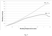
- FIG. 9 is a diagram schematically illustrating a bending load-bearing performance comparison between the elastic tubes respectively adopting the conventional transverse slot and the modified transverse slot of Fig. 7a , in which the horizontal axis represents the bending displacement (measured in mm) and in which the vertical axis represents the bending load (measured in gram).
- the transverse slot 11 may extend in a curved shape on the circumferential surface of the elastic tube 1. That is, the transverse slot 11 appears curved in a front view of the elastic tube 1, and arc-shaped in a top view of the elastic tube 1.
- the transverse slot is formed in the elastic tube 1 by a laser cutting.
- the force sensor 10 further includes strain gauge(s) arranged on the outer wall of the elastic tube 1. The number of the strain gauge(s) corresponds to the number of the transverse slot(s). Each strain gauge may be provided on either a pierced or non-pierced section of the elastic tube 1.
- each strain gauge is arranged on a non-pierced section of the elastic tube 1. More preferably, a plurality of the transverse slots 11 are axially spaced apart from one another across the elastic tube 1 and staggered from one another along the circumferential direction thereof, with each strain gauge preferably disposed between opposing ends of the respective transverse slot.
- the force sensor includes an elastic tube and a strain gauge arranged on the elastic tube.
- a transverse slot is formed in the elastic tube, and at least one first limiting structure is disposed between opposing ends of the transverse slot.
- Each first limiting structure includes a first limiting portion connected to a wall of the transverse slot and a second limiting portion connected to the other wall of the transverse slot.
- the transverse slot is maintained within a predetermined deformation range that can avoid breakage of the elastic tube and result in a prolonged service life of the strain gauge.
- adding one or more such limiting structures will not lead to increased structural complexity or impaired overall appearance of the elastic tube, and the limiting structures themselves are very easy to form and suitable for industrial production and use.
Landscapes
- Health & Medical Sciences (AREA)
- Life Sciences & Earth Sciences (AREA)
- Surgery (AREA)
- Engineering & Computer Science (AREA)
- Physics & Mathematics (AREA)
- General Health & Medical Sciences (AREA)
- Animal Behavior & Ethology (AREA)
- Veterinary Medicine (AREA)
- Public Health (AREA)
- Molecular Biology (AREA)
- Biomedical Technology (AREA)
- Heart & Thoracic Surgery (AREA)
- Medical Informatics (AREA)
- Nuclear Medicine, Radiotherapy & Molecular Imaging (AREA)
- Otolaryngology (AREA)
- Cardiology (AREA)
- Plasma & Fusion (AREA)
- General Physics & Mathematics (AREA)
- Biophysics (AREA)
- Pathology (AREA)
- Vascular Medicine (AREA)
- Physiology (AREA)
- Media Introduction/Drainage Providing Device (AREA)
Claims (12)
- Kraftsensor (10), umfassend ein elastisches Rohr (1) und einen auf dem elastischen Rohr (1) angeordneten Dehnungsmessstreifen, wobei:der Kraftsensor (10) ferner einen durchbohrten Querschlitz (11) umfasst, der in dem elastischen Rohr (1) gebildet ist, wobei der Querschlitz (11) eine erste Wand (111) und eine zweite Wand (112) aufweist;der Kraftsensor (10) dadurch gekennzeichnet ist, dass er ferner mindestens eine erste Begrenzungsstruktur umfasst, die zwischen zwei gegenüberliegenden Enden des Querschlitzes (11) angeordnet ist, wobei jede der mindestens ersten Begrenzungsstrukturen einen ersten Begrenzungsabschnitt (13) und einen zweiten Begrenzungsabschnitt (14) umfasst, wobei der erste Begrenzungsabschnitt (13) mit der ersten Wand (111) verbunden ist, wobei der zweite Begrenzungsabschnitt (14) mit der zweiten Wand (112) verbunden ist; wobei der erste Begrenzungsabschnitt (13) ein weiblicher Abschnitt mit einer ersten Innenfläche und der zweite Begrenzungsabschnitt (14) ein männlicher Abschnitt mit einer zweiten Außenfläche ist, wobei die erste Innenfläche und die zweite Außenfläche einander gegenüberliegend angeordnet sind und einen Abstand zwischen der ersten Innenfläche und der zweiten Außenfläche definieren, und wobei der zweite Begrenzungsabschnitt (14) innerhalb des ersten Begrenzungsabschnitts (13) eingeschlossen ist; undwenn das elastische Rohr durch eine Kraft gedehnt wird und sich der Querschlitz (11) in einer axialen Richtung des elastischen Rohrs (1) verformt, der erste Begrenzungsabschnitt (13) und der zweite Begrenzungsabschnitt (14) ausgebildet sind, sich in der axialen Richtung reaktiv voneinander weg zu bewegen, bis sie miteinander eingegriffen werden;wobei der erste Begrenzungsabschnitt (13) und der zweite Begrenzungsabschnitt (14) beide L-förmige Abschnitte sind, deren Form zueinander passt; oder wobei der erste Begrenzungsabschnitt (13) ein trapezförmiger männlicher Abschnitt und der zweite Begrenzungsabschnitt (14) ein trapezförmiger weiblicher Abschnitt ist.
- Kraftsensor (10) nach Anspruch 1, wobei der Kraftsensor (10) eine Vielzahl der ersten Begrenzungsstrukturen umfasst, die über eine gleiche Umfangsfläche voneinander beabstandet sind.
- Kraftsensor (10) nach Anspruch 1, ferner umfassend mindestens eine zweite Begrenzungsstruktur, die zwischen den gegenüberliegenden Enden des Querschlitzes (11) angeordnet ist, wobei jede der mindestens einen zweiten Begrenzungsstrukturen einen dritten Begrenzungsabschnitt (15), der mit der ersten Wand (111) verbunden ist, und einen vierten Begrenzungsabschnitt (16) umfasst, der mit der zweiten Wand (112) verbunden ist, und
wobei, wenn sich der Querschlitz (11) axial verformt, der dritte Begrenzungsabschnitt (15) und vierter Begrenzungsabschnitt (16) ausgebildet sind, sich relativ zueinander reaktiv zu bewegen, bis sie miteinander eingegriffen werden. - Kraftsensor (10) nach Anspruch 3, wobei der dritte Begrenzungsabschnitt (15) ein männlicher Abschnitt mit einer dritten Außenfläche und der vierte Begrenzungsabschnitt (16) ein weiblicher Abschnitt mit einer vierten Außenfläche ist, wobei die dritte Außenfläche und die vierte Außenfläche einander gegenüberliegend angeordnet sind und einen Abstand zwischen der dritten Außenfläche und der vierten Außenfläche definieren, und wobei der dritte Begrenzungsabschnitt (15) innerhalb des vierten Begrenzungsabschnitts (16) eingeschlossen ist.
- Kraftsensor (10) nach Anspruch 3, wobei der erste Begrenzungsabschnitt (13), zweite Begrenzungsabschnitt (14), dritte Begrenzungsabschnitt (15) und vierter Begrenzungsabschnitt (16) eine gleiche Form aufweisen.
- Kraftsensor (10) nach Anspruch 5, wobei der Kraftsensor (10) eine Vielzahl der ersten Begrenzungsstrukturen umfasst, und wobei jede der mindestens einen zweiten Begrenzungsstrukturen zwischen zwei benachbarten der ersten Begrenzungsstrukturen angeordnet ist, wobei der dritte Begrenzungsabschnitt (15) ein Abschnitt zwischen zwei davon benachbarten der ersten Begrenzungsabschnitte (13) ist, und wobei der vierte Begrenzungsabschnitt (16) ein Spalt zwischen zwei benachbarten der zweiten Begrenzungsabschnitte (14) ist.
- Kraftsensor (10) nach Anspruch 5, wobei eine Außenfläche des zweiten Begrenzungsabschnitts (14) und eine Außenfläche des dritten Begrenzungsabschnitts (15) einander axial gegenüberliegend angeordnet sind und einen Abstand zwischen der Außenfläche des zweiten Begrenzungsabschnitts (14) und der Außenfläche des dritten Begrenzungsabschnitts (15) definieren.
- Kraftsensor (10) nach Anspruch 7, wobei der zweite Begrenzungsabschnitt (14) einen zweiten vertikalen Abschnitt und einen zweiten horizontalen Abschnitt umfasst, und wobei der dritte Begrenzungsabschnitt (15) einen dritten vertikalen Abschnitt und einen dritten horizontalen Abschnitt umfasst, wobei der zweite vertikale Abschnitt mit der zweiten Wand (112) verbunden ist, wobei der dritte vertikale Abschnitt mit der ersten Wand (111) verbunden ist, wobei der zweite und der dritte horizontale Abschnitt zusammen einen Eingriff bilden.
- Kraftsensor (10) nach Anspruch 1, wobei der Kraftsensor (10) ferner zwei Längsschlitze (12) umfasst, die an den jeweils gegenüberliegenden Enden des Querschlitzes (11) angeordnet sind.
- Kraftsensor (10) nach Anspruch 1, wobei der Querschlitz (11) in einer gekrümmten Form auf einer Umfangsfläche des elastischen Rohrs (1) verläuft; oder
wobei der Querschlitz (11) durch Laserschneiden in dem elastischen Rohr (1) geformt ist. - Kraftsensor (10) nach Anspruch 1, wobei der Kraftsensor (10) eine Vielzahl von Querschlitzen (11) und eine Vielzahl von Dehnungsmessstreifen umfasst, wobei die Querschlitze (11) in axialer Richtung des elastischen Rohrs (1) über das elastische Rohr (1) voneinander beabstandet sind und entlang einer Umfangsrichtung des elastischen Rohrs (1) zueinander versetzt sind, wobei jeder der Dehnungsmessstreifen zwischen zwei gegenüberliegenden Enden eines entsprechenden der Querschlitze (11) angeordnet ist.
- Elektrophysiologiekatheter, umfassend ein distales Ende und einen Kraftsensor (10) nach einem der Ansprüche 1 bis 11, wobei der Kraftsensor (10) an dem distalen Ende angeordnet ist.
Applications Claiming Priority (2)
| Application Number | Priority Date | Filing Date | Title |
|---|---|---|---|
| CN201810142142.XA CN110160676B (zh) | 2018-02-11 | 2018-02-11 | 压力传感器及其电生理导管 |
| PCT/CN2019/074760 WO2019154409A1 (zh) | 2018-02-11 | 2019-02-11 | 压力传感器及电生理导管 |
Publications (3)
| Publication Number | Publication Date |
|---|---|
| EP3751247A1 EP3751247A1 (de) | 2020-12-16 |
| EP3751247A4 EP3751247A4 (de) | 2021-04-07 |
| EP3751247B1 true EP3751247B1 (de) | 2024-12-18 |
Family
ID=67548747
Family Applications (1)
| Application Number | Title | Priority Date | Filing Date |
|---|---|---|---|
| EP19751623.0A Active EP3751247B1 (de) | 2018-02-11 | 2019-02-11 | Kraftsensor und elektrophysiologischer katheter |
Country Status (7)
| Country | Link |
|---|---|
| US (1) | US20200360082A1 (de) |
| EP (1) | EP3751247B1 (de) |
| CN (1) | CN110160676B (de) |
| AU (1) | AU2019218510B2 (de) |
| ES (1) | ES3001016T3 (de) |
| RU (1) | RU2752593C1 (de) |
| WO (1) | WO2019154409A1 (de) |
Families Citing this family (3)
| Publication number | Priority date | Publication date | Assignee | Title |
|---|---|---|---|---|
| GB2572809B (en) * | 2018-04-12 | 2020-11-11 | Subsea 7 Ltd | Internal inspection of pipelines |
| CN217066330U (zh) * | 2021-12-30 | 2022-07-29 | 微创优通医疗科技(上海)有限公司 | 弹性管、探测器插入结构及柔性探测器 |
| CN118418193B (zh) * | 2024-07-02 | 2024-09-20 | 德瑞精工(深圳)有限公司 | 防过载压力闭环zr轴模组及其制备方法 |
Family Cites Families (21)
| Publication number | Priority date | Publication date | Assignee | Title |
|---|---|---|---|---|
| FR2439291A1 (fr) * | 1978-10-19 | 1980-05-16 | Inst Francais Du Petrole | Nouveau dispositif de mesure des contraintes s'appliquant a une garniture de forage en service |
| DE19535179A1 (de) * | 1995-09-22 | 1997-03-27 | Wolf Gmbh Richard | Abwinkelbares Rohr und Verfahren zu seiner Herstellung |
| EP2299917A1 (de) * | 2008-06-10 | 2011-03-30 | Sonoma Orthopedic Products, Inc. | Frakturfixationsvorrichtung, werkzeuge und verfahren |
| US8118775B2 (en) * | 2008-09-09 | 2012-02-21 | Biosense Webster, Inc. | Deflectable catheter with bonded center strut and method of manufacture for same |
| US8454504B2 (en) * | 2010-02-24 | 2013-06-04 | Meni-Med Ltd | Surgical retractor |
| CN102375586B (zh) * | 2010-08-19 | 2014-12-03 | 苏州敏芯微电子技术有限公司 | 识别指向与力度的操纵系统 |
| CN202678568U (zh) * | 2012-06-21 | 2013-01-16 | 长谷川精密科技股份有限公司 | 弹片结构 |
| US20140041673A1 (en) * | 2012-08-13 | 2014-02-13 | Christopher C. Walters | Devices for containing fluid and debris on endotracheal tubes, laryngeal masks, endoscopes, bronchoscopes and catheters and method of use thereof |
| CN202982206U (zh) * | 2012-10-15 | 2013-06-12 | 陈平根 | 一种多极射频消融导管 |
| CN102860867B (zh) * | 2012-10-15 | 2014-11-05 | 陈平根 | 一种多极射频消融导管及设计方法 |
| WO2014174662A1 (ja) * | 2013-04-26 | 2014-10-30 | テルモ株式会社 | アブレーションカテーテル |
| EP3009104B1 (de) * | 2014-10-14 | 2019-11-20 | St. Jude Medical, Cardiology Division, Inc. | Flexibler katheter und verfahren zur herstellung davon |
| US11007345B2 (en) * | 2016-10-05 | 2021-05-18 | Orbusneich Medical Pte. Ltd. | Modular vascular catheter |
| CN104398330B (zh) * | 2014-12-19 | 2017-07-07 | 湖南埃普特医疗器械有限公司 | 支架输送系统 |
| CN106264719B (zh) * | 2016-07-29 | 2019-07-23 | 上海微创电生理医疗科技股份有限公司 | 电生理导管 |
| CN106768535B (zh) * | 2017-01-12 | 2023-06-16 | 福建省莆田市衡力传感器有限公司 | 双量程检测带过载保护扭矩传感器及其制造方法 |
| CN107091261B (zh) * | 2017-02-14 | 2020-10-09 | 珠海普生医疗科技有限公司 | 一种蛇骨的加工方法 |
| CN108720919B (zh) * | 2017-04-24 | 2019-07-09 | 四川锦江电子科技有限公司 | 一种具有柔性远端的消融导管 |
| CN106974724B (zh) * | 2017-04-24 | 2019-12-03 | 四川锦江电子科技有限公司 | 一种具有压力检测功能的消融导管 |
| CN107477124A (zh) * | 2017-08-08 | 2017-12-15 | 扬州中碟弹簧制造有限公司 | 一种抗拉伸及压缩的弹簧 |
| CN107496055B (zh) * | 2017-08-10 | 2021-06-08 | 上海微创心通医疗科技有限公司 | 心脏瓣膜输送导管及输送系统 |
-
2018
- 2018-02-11 CN CN201810142142.XA patent/CN110160676B/zh active Active
-
2019
- 2019-02-11 ES ES19751623T patent/ES3001016T3/es active Active
- 2019-02-11 US US16/967,327 patent/US20200360082A1/en not_active Abandoned
- 2019-02-11 WO PCT/CN2019/074760 patent/WO2019154409A1/zh not_active Ceased
- 2019-02-11 EP EP19751623.0A patent/EP3751247B1/de active Active
- 2019-02-11 AU AU2019218510A patent/AU2019218510B2/en active Active
- 2019-02-11 RU RU2020129581A patent/RU2752593C1/ru active
Also Published As
| Publication number | Publication date |
|---|---|
| AU2019218510B2 (en) | 2021-03-11 |
| CN110160676B (zh) | 2021-10-26 |
| ES3001016T3 (es) | 2025-03-04 |
| WO2019154409A1 (zh) | 2019-08-15 |
| US20200360082A1 (en) | 2020-11-19 |
| EP3751247A4 (de) | 2021-04-07 |
| EP3751247A1 (de) | 2020-12-16 |
| AU2019218510A1 (en) | 2020-09-17 |
| CN110160676A (zh) | 2019-08-23 |
| RU2752593C1 (ru) | 2021-07-29 |
Similar Documents
| Publication | Publication Date | Title |
|---|---|---|
| US20220387101A1 (en) | Catheter with atraumatic tip | |
| EP3492033B1 (de) | Kraftsensor für einen elektrophysiologischen katheter | |
| EP2327365B1 (de) | Katheter mit Druckmessungsspitze | |
| EP2420196B1 (de) | Katheter mit distaler Spitze und Dünnfilmdrucksensor | |
| AU2019218510B2 (en) | Pressure sensor, and electrophysiology catheter | |
| EP2749214B1 (de) | Zwei-Schlingen-Lasso mit Einzel-Zugdraht für bidirektionale Betätigung | |
| EP3095482A1 (de) | Katheter mit verstellbarer deflektion | |
| EP3624717B1 (de) | Optisches kraftmessendes kathetersystem | |
| EP3629894B1 (de) | Katheter und federelement zur kontaktkrafterfassung | |
| KR20230029758A (ko) | 편향가능 세장형 가이드와이어 조립체 | |
| US20200323585A1 (en) | Ablation catheter tip with flexible electronic circuitry | |
| US12005216B2 (en) | Esophageal deviator | |
| EP4410185B1 (de) | Arrhythmie-diagnoseelektrodenvorrichtung mit reduzierter direktionaler steifigkeit | |
| CN118266892A (zh) | 具有减小的方向性刚度的心律失常诊断电极设备 | |
| AU2015202746A1 (en) | Catheter with pressure measuring tip |
Legal Events
| Date | Code | Title | Description |
|---|---|---|---|
| STAA | Information on the status of an ep patent application or granted ep patent |
Free format text: STATUS: THE INTERNATIONAL PUBLICATION HAS BEEN MADE |
|
| PUAI | Public reference made under article 153(3) epc to a published international application that has entered the european phase |
Free format text: ORIGINAL CODE: 0009012 |
|
| STAA | Information on the status of an ep patent application or granted ep patent |
Free format text: STATUS: REQUEST FOR EXAMINATION WAS MADE |
|
| 17P | Request for examination filed |
Effective date: 20200811 |
|
| AK | Designated contracting states |
Kind code of ref document: A1 Designated state(s): AL AT BE BG CH CY CZ DE DK EE ES FI FR GB GR HR HU IE IS IT LI LT LU LV MC MK MT NL NO PL PT RO RS SE SI SK SM TR |
|
| AX | Request for extension of the european patent |
Extension state: BA ME |
|
| A4 | Supplementary search report drawn up and despatched |
Effective date: 20210305 |
|
| RIC1 | Information provided on ipc code assigned before grant |
Ipc: A61B 18/12 20060101ALI20210301BHEP Ipc: A61M 25/00 20060101ALI20210301BHEP Ipc: G01L 1/04 20060101AFI20210301BHEP Ipc: A61B 18/00 20060101ALI20210301BHEP Ipc: G01L 1/22 20060101ALI20210301BHEP |
|
| DAV | Request for validation of the european patent (deleted) | ||
| DAX | Request for extension of the european patent (deleted) | ||
| STAA | Information on the status of an ep patent application or granted ep patent |
Free format text: STATUS: EXAMINATION IS IN PROGRESS |
|
| 17Q | First examination report despatched |
Effective date: 20230626 |
|
| GRAP | Despatch of communication of intention to grant a patent |
Free format text: ORIGINAL CODE: EPIDOSNIGR1 |
|
| STAA | Information on the status of an ep patent application or granted ep patent |
Free format text: STATUS: GRANT OF PATENT IS INTENDED |
|
| RIC1 | Information provided on ipc code assigned before grant |
Ipc: A61B 90/00 20160101ALI20240814BHEP Ipc: A61B 9/00 20060101ALI20240814BHEP Ipc: A61B 18/14 20060101ALI20240814BHEP Ipc: A61B 5/00 20060101ALI20240814BHEP Ipc: A61B 5/0215 20060101ALI20240814BHEP Ipc: G01L 1/22 20060101ALI20240814BHEP Ipc: A61M 25/00 20060101ALI20240814BHEP Ipc: A61B 18/00 20060101ALI20240814BHEP Ipc: A61B 18/12 20060101ALI20240814BHEP Ipc: G01L 1/04 20060101AFI20240814BHEP |
|
| INTG | Intention to grant announced |
Effective date: 20240826 |
|
| GRAS | Grant fee paid |
Free format text: ORIGINAL CODE: EPIDOSNIGR3 |
|
| GRAA | (expected) grant |
Free format text: ORIGINAL CODE: 0009210 |
|
| STAA | Information on the status of an ep patent application or granted ep patent |
Free format text: STATUS: THE PATENT HAS BEEN GRANTED |
|
| AK | Designated contracting states |
Kind code of ref document: B1 Designated state(s): AL AT BE BG CH CY CZ DE DK EE ES FI FR GB GR HR HU IE IS IT LI LT LU LV MC MK MT NL NO PL PT RO RS SE SI SK SM TR |
|
| REG | Reference to a national code |
Ref country code: CH Ref legal event code: EP |
|
| REG | Reference to a national code |
Ref country code: DE Ref legal event code: R096 Ref document number: 602019063670 Country of ref document: DE |
|
| REG | Reference to a national code |
Ref country code: IE Ref legal event code: FG4D Ref country code: NL Ref legal event code: FP |
|
| REG | Reference to a national code |
Ref country code: ES Ref legal event code: FG2A Ref document number: 3001016 Country of ref document: ES Kind code of ref document: T3 Effective date: 20250304 |
|
| REG | Reference to a national code |
Ref country code: LT Ref legal event code: MG9D |
|
| PG25 | Lapsed in a contracting state [announced via postgrant information from national office to epo] |
Ref country code: HR Free format text: LAPSE BECAUSE OF FAILURE TO SUBMIT A TRANSLATION OF THE DESCRIPTION OR TO PAY THE FEE WITHIN THE PRESCRIBED TIME-LIMIT Effective date: 20241218 |
|
| PG25 | Lapsed in a contracting state [announced via postgrant information from national office to epo] |
Ref country code: FI Free format text: LAPSE BECAUSE OF FAILURE TO SUBMIT A TRANSLATION OF THE DESCRIPTION OR TO PAY THE FEE WITHIN THE PRESCRIBED TIME-LIMIT Effective date: 20241218 |
|
| PG25 | Lapsed in a contracting state [announced via postgrant information from national office to epo] |
Ref country code: BG Free format text: LAPSE BECAUSE OF FAILURE TO SUBMIT A TRANSLATION OF THE DESCRIPTION OR TO PAY THE FEE WITHIN THE PRESCRIBED TIME-LIMIT Effective date: 20241218 |
|
| PG25 | Lapsed in a contracting state [announced via postgrant information from national office to epo] |
Ref country code: NO Free format text: LAPSE BECAUSE OF FAILURE TO SUBMIT A TRANSLATION OF THE DESCRIPTION OR TO PAY THE FEE WITHIN THE PRESCRIBED TIME-LIMIT Effective date: 20250318 |
|
| PG25 | Lapsed in a contracting state [announced via postgrant information from national office to epo] |
Ref country code: LV Free format text: LAPSE BECAUSE OF FAILURE TO SUBMIT A TRANSLATION OF THE DESCRIPTION OR TO PAY THE FEE WITHIN THE PRESCRIBED TIME-LIMIT Effective date: 20241218 Ref country code: GR Free format text: LAPSE BECAUSE OF FAILURE TO SUBMIT A TRANSLATION OF THE DESCRIPTION OR TO PAY THE FEE WITHIN THE PRESCRIBED TIME-LIMIT Effective date: 20250319 |
|
| PG25 | Lapsed in a contracting state [announced via postgrant information from national office to epo] |
Ref country code: RS Free format text: LAPSE BECAUSE OF FAILURE TO SUBMIT A TRANSLATION OF THE DESCRIPTION OR TO PAY THE FEE WITHIN THE PRESCRIBED TIME-LIMIT Effective date: 20250318 |
|
| REG | Reference to a national code |
Ref country code: AT Ref legal event code: MK05 Ref document number: 1752562 Country of ref document: AT Kind code of ref document: T Effective date: 20241218 |
|
| PG25 | Lapsed in a contracting state [announced via postgrant information from national office to epo] |
Ref country code: SM Free format text: LAPSE BECAUSE OF FAILURE TO SUBMIT A TRANSLATION OF THE DESCRIPTION OR TO PAY THE FEE WITHIN THE PRESCRIBED TIME-LIMIT Effective date: 20241218 |
|
| PG25 | Lapsed in a contracting state [announced via postgrant information from national office to epo] |
Ref country code: PL Free format text: LAPSE BECAUSE OF FAILURE TO SUBMIT A TRANSLATION OF THE DESCRIPTION OR TO PAY THE FEE WITHIN THE PRESCRIBED TIME-LIMIT Effective date: 20241218 |
|
| PGFP | Annual fee paid to national office [announced via postgrant information from national office to epo] |
Ref country code: ES Payment date: 20250331 Year of fee payment: 7 |
|
| PG25 | Lapsed in a contracting state [announced via postgrant information from national office to epo] |
Ref country code: IS Free format text: LAPSE BECAUSE OF FAILURE TO SUBMIT A TRANSLATION OF THE DESCRIPTION OR TO PAY THE FEE WITHIN THE PRESCRIBED TIME-LIMIT Effective date: 20250418 |
|
| PG25 | Lapsed in a contracting state [announced via postgrant information from national office to epo] |
Ref country code: PT Free format text: LAPSE BECAUSE OF FAILURE TO SUBMIT A TRANSLATION OF THE DESCRIPTION OR TO PAY THE FEE WITHIN THE PRESCRIBED TIME-LIMIT Effective date: 20250421 |
|
| PG25 | Lapsed in a contracting state [announced via postgrant information from national office to epo] |
Ref country code: EE Free format text: LAPSE BECAUSE OF FAILURE TO SUBMIT A TRANSLATION OF THE DESCRIPTION OR TO PAY THE FEE WITHIN THE PRESCRIBED TIME-LIMIT Effective date: 20241218 |
|
| PG25 | Lapsed in a contracting state [announced via postgrant information from national office to epo] |
Ref country code: AT Free format text: LAPSE BECAUSE OF FAILURE TO SUBMIT A TRANSLATION OF THE DESCRIPTION OR TO PAY THE FEE WITHIN THE PRESCRIBED TIME-LIMIT Effective date: 20241218 Ref country code: RO Free format text: LAPSE BECAUSE OF FAILURE TO SUBMIT A TRANSLATION OF THE DESCRIPTION OR TO PAY THE FEE WITHIN THE PRESCRIBED TIME-LIMIT Effective date: 20241218 |
|
| PG25 | Lapsed in a contracting state [announced via postgrant information from national office to epo] |
Ref country code: SK Free format text: LAPSE BECAUSE OF FAILURE TO SUBMIT A TRANSLATION OF THE DESCRIPTION OR TO PAY THE FEE WITHIN THE PRESCRIBED TIME-LIMIT Effective date: 20241218 |
|
| PG25 | Lapsed in a contracting state [announced via postgrant information from national office to epo] |
Ref country code: CZ Free format text: LAPSE BECAUSE OF FAILURE TO SUBMIT A TRANSLATION OF THE DESCRIPTION OR TO PAY THE FEE WITHIN THE PRESCRIBED TIME-LIMIT Effective date: 20241218 |
|
| PG25 | Lapsed in a contracting state [announced via postgrant information from national office to epo] |
Ref country code: SE Free format text: LAPSE BECAUSE OF FAILURE TO SUBMIT A TRANSLATION OF THE DESCRIPTION OR TO PAY THE FEE WITHIN THE PRESCRIBED TIME-LIMIT Effective date: 20241218 |
|
| PG25 | Lapsed in a contracting state [announced via postgrant information from national office to epo] |
Ref country code: MC Free format text: LAPSE BECAUSE OF FAILURE TO SUBMIT A TRANSLATION OF THE DESCRIPTION OR TO PAY THE FEE WITHIN THE PRESCRIBED TIME-LIMIT Effective date: 20241218 |
|
| REG | Reference to a national code |
Ref country code: DE Ref legal event code: R097 Ref document number: 602019063670 Country of ref document: DE |
|
| REG | Reference to a national code |
Ref country code: CH Ref legal event code: PL |
|
| PG25 | Lapsed in a contracting state [announced via postgrant information from national office to epo] |
Ref country code: DK Free format text: LAPSE BECAUSE OF FAILURE TO SUBMIT A TRANSLATION OF THE DESCRIPTION OR TO PAY THE FEE WITHIN THE PRESCRIBED TIME-LIMIT Effective date: 20241218 |
|
| PG25 | Lapsed in a contracting state [announced via postgrant information from national office to epo] |
Ref country code: LU Free format text: LAPSE BECAUSE OF NON-PAYMENT OF DUE FEES Effective date: 20250211 |
|
| PG25 | Lapsed in a contracting state [announced via postgrant information from national office to epo] |
Ref country code: CH Free format text: LAPSE BECAUSE OF NON-PAYMENT OF DUE FEES Effective date: 20250228 |
|
| PLBE | No opposition filed within time limit |
Free format text: ORIGINAL CODE: 0009261 |
|
| STAA | Information on the status of an ep patent application or granted ep patent |
Free format text: STATUS: NO OPPOSITION FILED WITHIN TIME LIMIT |
|
| 26N | No opposition filed |
Effective date: 20250919 |
|
| PG25 | Lapsed in a contracting state [announced via postgrant information from national office to epo] |
Ref country code: IE Free format text: LAPSE BECAUSE OF NON-PAYMENT OF DUE FEES Effective date: 20250211 |
|
| PGFP | Annual fee paid to national office [announced via postgrant information from national office to epo] |
Ref country code: NL Payment date: 20260218 Year of fee payment: 8 |
|
| PGFP | Annual fee paid to national office [announced via postgrant information from national office to epo] |
Ref country code: GB Payment date: 20260220 Year of fee payment: 8 |
|
| PGFP | Annual fee paid to national office [announced via postgrant information from national office to epo] |
Ref country code: DE Payment date: 20260218 Year of fee payment: 8 |
|
| PGFP | Annual fee paid to national office [announced via postgrant information from national office to epo] |
Ref country code: BE Payment date: 20260218 Year of fee payment: 8 Ref country code: IT Payment date: 20260224 Year of fee payment: 8 |
|
| PGFP | Annual fee paid to national office [announced via postgrant information from national office to epo] |
Ref country code: FR Payment date: 20260218 Year of fee payment: 8 |