EP3751247B1 - Force sensor, and electrophysiology catheter - Google Patents
Force sensor, and electrophysiology catheter Download PDFInfo
- Publication number
- EP3751247B1 EP3751247B1 EP19751623.0A EP19751623A EP3751247B1 EP 3751247 B1 EP3751247 B1 EP 3751247B1 EP 19751623 A EP19751623 A EP 19751623A EP 3751247 B1 EP3751247 B1 EP 3751247B1
- Authority
- EP
- European Patent Office
- Prior art keywords
- limiting
- limiting portion
- force sensor
- elastic tube
- transverse slot
- Prior art date
- Legal status (The legal status is an assumption and is not a legal conclusion. Google has not performed a legal analysis and makes no representation as to the accuracy of the status listed.)
- Active
Links
Images





Classifications
-
- G—PHYSICS
- G01—MEASURING; TESTING
- G01L—MEASURING FORCE, STRESS, TORQUE, WORK, MECHANICAL POWER, MECHANICAL EFFICIENCY, OR FLUID PRESSURE
- G01L1/00—Measuring force or stress, in general
- G01L1/20—Measuring force or stress, in general by measuring variations in ohmic resistance of solid materials or of electrically-conductive fluids; by making use of electrokinetic cells, i.e. liquid-containing cells wherein an electrical potential is produced or varied upon the application of stress
- G01L1/22—Measuring force or stress, in general by measuring variations in ohmic resistance of solid materials or of electrically-conductive fluids; by making use of electrokinetic cells, i.e. liquid-containing cells wherein an electrical potential is produced or varied upon the application of stress using resistance strain gauges
-
- A—HUMAN NECESSITIES
- A61—MEDICAL OR VETERINARY SCIENCE; HYGIENE
- A61B—DIAGNOSIS; SURGERY; IDENTIFICATION
- A61B18/00—Surgical instruments, devices or methods for transferring non-mechanical forms of energy to or from the body
-
- A—HUMAN NECESSITIES
- A61—MEDICAL OR VETERINARY SCIENCE; HYGIENE
- A61B—DIAGNOSIS; SURGERY; IDENTIFICATION
- A61B18/00—Surgical instruments, devices or methods for transferring non-mechanical forms of energy to or from the body
- A61B18/04—Surgical instruments, devices or methods for transferring non-mechanical forms of energy to or from the body by heating
- A61B18/12—Surgical instruments, devices or methods for transferring non-mechanical forms of energy to or from the body by heating by passing a current through the tissue to be heated, e.g. high-frequency current
-
- A—HUMAN NECESSITIES
- A61—MEDICAL OR VETERINARY SCIENCE; HYGIENE
- A61B—DIAGNOSIS; SURGERY; IDENTIFICATION
- A61B18/00—Surgical instruments, devices or methods for transferring non-mechanical forms of energy to or from the body
- A61B18/04—Surgical instruments, devices or methods for transferring non-mechanical forms of energy to or from the body by heating
- A61B18/12—Surgical instruments, devices or methods for transferring non-mechanical forms of energy to or from the body by heating by passing a current through the tissue to be heated, e.g. high-frequency current
- A61B18/14—Probes or electrodes therefor
- A61B18/1492—Probes or electrodes therefor having a flexible, catheter-like structure, e.g. for heart ablation
-
- A—HUMAN NECESSITIES
- A61—MEDICAL OR VETERINARY SCIENCE; HYGIENE
- A61B—DIAGNOSIS; SURGERY; IDENTIFICATION
- A61B5/00—Measuring for diagnostic purposes; Identification of persons
- A61B5/02—Detecting, measuring or recording for evaluating the cardiovascular system, e.g. pulse, heart rate, blood pressure or blood flow
- A61B5/021—Measuring pressure in heart or blood vessels
- A61B5/0215—Measuring pressure in heart or blood vessels by means inserted into the body
-
- A—HUMAN NECESSITIES
- A61—MEDICAL OR VETERINARY SCIENCE; HYGIENE
- A61B—DIAGNOSIS; SURGERY; IDENTIFICATION
- A61B5/00—Measuring for diagnostic purposes; Identification of persons
- A61B5/68—Arrangements of detecting, measuring or recording means, e.g. sensors, in relation to patient
- A61B5/6846—Arrangements of detecting, measuring or recording means, e.g. sensors, in relation to patient specially adapted to be brought in contact with an internal body part, i.e. invasive
- A61B5/6847—Arrangements of detecting, measuring or recording means, e.g. sensors, in relation to patient specially adapted to be brought in contact with an internal body part, i.e. invasive mounted on an invasive device
- A61B5/6852—Catheters
-
- G—PHYSICS
- G01—MEASURING; TESTING
- G01L—MEASURING FORCE, STRESS, TORQUE, WORK, MECHANICAL POWER, MECHANICAL EFFICIENCY, OR FLUID PRESSURE
- G01L1/00—Measuring force or stress, in general
- G01L1/04—Measuring force or stress, in general by measuring elastic deformation of gauges, e.g. of springs
-
- A—HUMAN NECESSITIES
- A61—MEDICAL OR VETERINARY SCIENCE; HYGIENE
- A61B—DIAGNOSIS; SURGERY; IDENTIFICATION
- A61B18/00—Surgical instruments, devices or methods for transferring non-mechanical forms of energy to or from the body
- A61B2018/00315—Surgical instruments, devices or methods for transferring non-mechanical forms of energy to or from the body for treatment of particular body parts
- A61B2018/00345—Vascular system
-
- A—HUMAN NECESSITIES
- A61—MEDICAL OR VETERINARY SCIENCE; HYGIENE
- A61B—DIAGNOSIS; SURGERY; IDENTIFICATION
- A61B18/00—Surgical instruments, devices or methods for transferring non-mechanical forms of energy to or from the body
- A61B2018/00315—Surgical instruments, devices or methods for transferring non-mechanical forms of energy to or from the body for treatment of particular body parts
- A61B2018/00345—Vascular system
- A61B2018/00351—Heart
-
- A—HUMAN NECESSITIES
- A61—MEDICAL OR VETERINARY SCIENCE; HYGIENE
- A61B—DIAGNOSIS; SURGERY; IDENTIFICATION
- A61B18/00—Surgical instruments, devices or methods for transferring non-mechanical forms of energy to or from the body
- A61B2018/00315—Surgical instruments, devices or methods for transferring non-mechanical forms of energy to or from the body for treatment of particular body parts
- A61B2018/00345—Vascular system
- A61B2018/00404—Blood vessels other than those in or around the heart
-
- A—HUMAN NECESSITIES
- A61—MEDICAL OR VETERINARY SCIENCE; HYGIENE
- A61B—DIAGNOSIS; SURGERY; IDENTIFICATION
- A61B18/00—Surgical instruments, devices or methods for transferring non-mechanical forms of energy to or from the body
- A61B2018/00315—Surgical instruments, devices or methods for transferring non-mechanical forms of energy to or from the body for treatment of particular body parts
- A61B2018/00434—Neural system
-
- A—HUMAN NECESSITIES
- A61—MEDICAL OR VETERINARY SCIENCE; HYGIENE
- A61B—DIAGNOSIS; SURGERY; IDENTIFICATION
- A61B18/00—Surgical instruments, devices or methods for transferring non-mechanical forms of energy to or from the body
- A61B2018/00571—Surgical instruments, devices or methods for transferring non-mechanical forms of energy to or from the body for achieving a particular surgical effect
- A61B2018/00577—Ablation
-
- A—HUMAN NECESSITIES
- A61—MEDICAL OR VETERINARY SCIENCE; HYGIENE
- A61B—DIAGNOSIS; SURGERY; IDENTIFICATION
- A61B18/00—Surgical instruments, devices or methods for transferring non-mechanical forms of energy to or from the body
- A61B2018/00636—Sensing and controlling the application of energy
- A61B2018/00773—Sensed parameters
-
- A—HUMAN NECESSITIES
- A61—MEDICAL OR VETERINARY SCIENCE; HYGIENE
- A61B—DIAGNOSIS; SURGERY; IDENTIFICATION
- A61B18/00—Surgical instruments, devices or methods for transferring non-mechanical forms of energy to or from the body
- A61B2018/00636—Sensing and controlling the application of energy
- A61B2018/00904—Automatic detection of target tissue
-
- A—HUMAN NECESSITIES
- A61—MEDICAL OR VETERINARY SCIENCE; HYGIENE
- A61B—DIAGNOSIS; SURGERY; IDENTIFICATION
- A61B90/00—Instruments, implements or accessories specially adapted for surgery or diagnosis and not covered by any of the groups A61B1/00 - A61B50/00, e.g. for luxation treatment or for protecting wound edges
- A61B90/06—Measuring instruments not otherwise provided for
- A61B2090/064—Measuring instruments not otherwise provided for for measuring force, pressure or mechanical tension
- A61B2090/065—Measuring instruments not otherwise provided for for measuring force, pressure or mechanical tension for measuring contact or contact pressure
-
- A—HUMAN NECESSITIES
- A61—MEDICAL OR VETERINARY SCIENCE; HYGIENE
- A61B—DIAGNOSIS; SURGERY; IDENTIFICATION
- A61B2562/00—Details of sensors; Constructional details of sensor housings or probes; Accessories for sensors
- A61B2562/02—Details of sensors specially adapted for in-vivo measurements
- A61B2562/0247—Pressure sensors
-
- A—HUMAN NECESSITIES
- A61—MEDICAL OR VETERINARY SCIENCE; HYGIENE
- A61B—DIAGNOSIS; SURGERY; IDENTIFICATION
- A61B2562/00—Details of sensors; Constructional details of sensor housings or probes; Accessories for sensors
- A61B2562/02—Details of sensors specially adapted for in-vivo measurements
- A61B2562/0261—Strain gauges
-
- A—HUMAN NECESSITIES
- A61—MEDICAL OR VETERINARY SCIENCE; HYGIENE
- A61M—DEVICES FOR INTRODUCING MEDIA INTO, OR ONTO, THE BODY; DEVICES FOR TRANSDUCING BODY MEDIA OR FOR TAKING MEDIA FROM THE BODY; DEVICES FOR PRODUCING OR ENDING SLEEP OR STUPOR
- A61M2205/00—General characteristics of the apparatus
- A61M2205/33—Controlling, regulating or measuring
- A61M2205/332—Force measuring means
Definitions
- the present invention relates to the technical field of medical instruments and, more specifically, to a force sensor and an electrophysiology catheter.
- an ablation or mapping catheter may be introduced into the heart via a vein or artery to find an aberrant electrical signal position or pathway by endocardial mapping, and then apply energy at the position or pathway to ablate it to eliminate or alter undesirable electrical signals, thus achieving curative results.
- an ablation catheter may be arterially introduced into an artery connecting the abdominal aorta and the kidney to ablate and block the parasympathetic nerve pathway to lower the blood pressure.
- Fig. 1 schematically illustrates a conventional electrophysiology catheter, with a force sensor, passing through an intracardiac guide sheath.
- a guide sheath 20 establishes a channel through which an electrophysiology catheter with a force sensor 10 can be delivered into the body to perform an associated interventional procedure.
- the electrophysiology catheter may be an ablation catheter, a mapping catheter or another type of electrophysiology catheter.
- the electrophysiology catheter includes a distal end at which the force sensor 10 is disposed.
- the force sensor 10 is configured to obtain the magnitude and direction of a contact force that occurs when the distal end of the catheter is brought into contact with the surface of a vessel wall or tissue.
- the force sensor 10 is configured to measure a reaction force in response to the contact force exerted by the catheter's distal end on the vessel wall or tissue.
- distinct guide sheaths 20 are designed with distal ends having different curved shapes. Additionally, such a guide sheath 20 should be constructed to be relatively stiff in order to maintain the designed curved shape while ensuring that a respective electrophysiology catheter can reach the target site. Consequently, as the electrophysiology catheter is guided through the guide sheath 20, the force sensor 10 tends to experience a great deformation under the action of significant forces exerted by the guide sheath 20.
- the force sensor 10 This requires the force sensor 10 to be able to withstand large bending loads. Otherwise, when impacted by a large force, the force sensor 10 may break, leading to failure or a shortened service life of a strain gauge therein due to a load exceeding its measuring range.
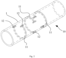
- the conventional force sensor 10 may include an elastic tube 1 having a wall in which one or more pierced transverse slots 11 (i.e., slots formed by cutting though the wall of the elastic tube 1) are formed in order to enhance elasticity of the elastic tube 1 (especially a metal tube) and amplify any deformation thereof under the action of the transverse slots 11.
- a strain gauge on the elastic tube 1 may then sense the amplified deformation and outputs an electrical signal indicating the change.
- multiple such transverse slots 11 are formed along different circumferential circles and spaced from one another circumferentially in a staggered manner. That is, orthographic projections of these transverse slots 11 on a single plane are preferably distributed in a circumferentially staggered pattern.
- Each transverse slot 11 is an arc-shaped slot cut along a circumference of the wall of the elastic tube 1 and provided at its both opposing ends each with a longitudinal slot 12 for mitigating stress concentration at the opposing ends of the transverse slot 11 and thus increasing its tensile strength.
- the transverse slot 11 when the elastic tube 1 is stretched, the transverse slot 11 will axially deform at its both axial sides away from the initial positions indicated by dashed lines in the figure, which will still cause the issue of "stress concentration" at the opposing ends.
- the transverse slot 11 may crack, or even break, at the opposing ends, leading to permanent failure of the strain gauge due to the excessive strain load exceeding its maximum measuring range.
- CN 106 264 719 A discloses an electrophysiological catheter including distal end of catheter provided with pressure transducer including elastic body and foil gauge.
- CN 107 496 055 A discloses a heart valve delivery catheter including outer tube assembly and an inner tube component arranged in the outer tube assembly.
- It is an objective of the present invention is to provide a force sensor and an electrophysiology catheter.
- the force sensor can be effectively avoided from experiencing any significant impact when the electrophysiology catheter is guided through a sheath. In this way, it is maintained within a predetermined deformation range that prevents breakage of an elastic tube of the sensor and enables an extended service life of any strain gauge therein.
- the present invention provides a force sensor as defined in claim 1.
- the force sensor further comprises at least one second limiting structure disposed between the opposing ends of the transverse slot, each of the at least one second limiting structure comprising a third limiting portion connected to the first wall and a fourth limiting portion connected to the second wall, and when the transverse slot deforms axially, the third limiting portion and fourth limiting portion are able to responsively move relative to each other until being engaged with each other.
- the third limiting portion is a male portion with a third external surface and the fourth limiting portion is a female portion with a fourth external surface, the third external surface and the forth external surface being arranged opposite to each other and defining a clearance between the third external surface and the forth external surface, and wherein the third limiting portion is confined within the fourth limiting portion.
- the first limiting portion, second limiting portion, third limiting portion and fourth limiting portion are of a same shape.
- the force sensor comprises a plurality of the first limiting structures, and wherein each of the at least one second limiting structure is disposed between adjacent two of the first limiting structures, the third limiting portion is a portion between adjacent two of the first limiting portions thereof and the fourth limiting portion is a gap between adjacent two of the second limiting portions.
- an external surface of the second limiting portion and an external surface of the third limiting portion are arranged axially opposite to each other and define a clearance between the external surface of the second limiting portion and the external surface of the third limiting portion.
- the second limiting portion comprises a second vertical portion and a second horizontal portion
- the third limiting portion comprises a third vertical portion and a third horizontal portion, the second vertical portion being connected to the second wall, the third vertical portion being connected to the first wall, the second and third horizontal portions together forming an engagement.
- the male portions are trapezoidal, L-shaped or T-shaped.
- the force sensor further comprises two longitudinal slots arranged at the respective opposing ends of the transverse slot.
- the transverse slot extends in a curved shape on a circumferential surface of the elastic tube.
- the transverse slot is formed in the elastic tube by laser cutting.
- the force sensor comprises a plurality of the transverse slots and a plurality of the strain gauges, the transverse slots spaced apart from one another across the elastic tube in an axial direction of the elastic tube and staggered from one another along a circumferential direction of the elastic tube, each of the strain gauges disposed between two opposing ends of a respective one of the transverse slots.
- the force sensor includes an elastic tube and a strain gauge arranged on the elastic tube.
- a pierced transverse slot is formed in the elastic tube, and at least one first limiting structure is disposed between two opposing ends of the transverse slot.
- Each first limiting structure includes a first limiting portion connected to a wall of the transverse slot and a second limiting portion connected to the other wall of the transverse slot.
- the first and second limiting portions will simultaneously move relative to each other.
- the two limiting portions will engage with each other.
- the transverse slot is maintained within a predetermined deformation range that can avoid breakage of the elastic tube and result in a prolonged service life of the strain gauge.
- proximal and distal describe relative orientations, positions and directions between elements or actions, viewed by a physician operating the product.
- proximal end usually refers to an end of the product close to the physician during normal operation
- distal end usually refers to an end thereof that enters the patient first.
- Axial and “longitudinal” refer to an axial direction of an elastic tube
- circumferential and “transverse” refer to a circumferential direction thereof.
- each transverse slot 11 is maintained within a predetermined deformation range that ensures that the elastic tube 1 will not break.
- at least one first limiting structure is added between opposing ends of each transverse slot 11.
- the at least one first limiting structure In response to an axial deformation of the transverse slot 11, a relative movement will occur in the at least one first limiting structure, and when reaching a limit position, an engagement will occur, defining a maximum deformation amount of the transverse slot 11.
- a relative movement will occur in the at least one first limiting structure, and when reaching a limit position, an engagement will occur, defining a maximum deformation amount of the transverse slot 11.
- the elastic tube 1 can be maintained within a predetermined deformation range that prevents breakage of the elastic tube and enables an extended service life of a strain gauge.
- a strain gauge provides a strain measurement range of ⁇ 20,000 microstrains.
- the at least one first limiting structure is generally configured to limit the maximum deformation amount to be not over 20,000 microstrains.
- each first limiting structure may include a first limiting portion and a second limiting portion.
- the first limiting portion is connected to a first wall of the transverse slot 11.
- the first limiting portion Upon any axial deformation of the first wall, the first limiting portion will experience a synchronous axial displacement.
- the second limiting portion is connected to a second wall of the transverse slot 11. Similarly, when the second wall deforms axially, a synchronous axial displacement will responsively occur to the second limiting portion.
- the first wall opposes the second wall along a widthwise direction of the transverse slot 11.
- both the first and second walls will deform accordingly, driving the first and second limiting portions to move relative to (i.e., toward or away from) each other.
- a predefined threshold e.g. 500 g
- the relative movement of the first and second limiting portions will be accommodated in a preset clearance without resulting in a contact therebetween.
- the first and second limiting portions will move toward or away from each other until the limit position is reached, where they cooperate to form a snap-fit engagement that prevents any of them from further moving.
- the transverse slot 11 deforms by a maximum allowable amount under the action of the snap-fit engagement of the first and second limiting portions.
- the maximum deformation amount of the transverse slot 11 in order to control the maximum deformation amount of the transverse slot 11, an axial clearance between the first and second limiting portions is necessary for allowing an axial relative movement between the two limiting portions while ensuring a space for compressive or tensile deformation of the elastic tube 1. Therefore, the maximum deformation amount can be controlled, in general terms, below 20,000 microstrains by suitably setting a dimension of the clearance.
- a transverse slot 11 formed in an elastic tube 1 has a first wall 111 and a second wall 112, arranged along a widthwise direction of the slot.
- the widthwise direction is defined as an axial direction when a center axis of the transverse slot coincides with a center axis of the elastic tube.
- a first limiting portion 13 is arranged on the first wall 111, while a second limiting portion 14 is arranged on the second wall 112.
- the first and second limiting portions 13, 14 are both L-shaped portions that match each other in shape.
- the first limiting portion 13 is a female L-shaped portion with a first internal surface
- the second limiting portion 14 is a male L-shaped portion with a second external surface.
- the first internal surface and the second external surface oppose each other with a clearance therebetween.
- the second limiting portion 14 is able to move with the transverse slot 11 relative to (i.e., to approach or get away from) the first limiting portion 13 while being always confined within the first limiting portion 13 without dislodging therefrom.
- a transverse slot 11 formed in an elastic tube 1 also has a first wall 111 and a second wall 112.
- a first limiting portion 13 is arranged on the first wall 111, while a second limiting portion 14 is arranged on the second wall 112.
- the first limiting portion 13 is a trapezoidal male portion, while the second limiting portion 14 is a trapezoidal female portion.
- the trapezoidal male and female portions will move away from each other until a limit position is reached where a maximum cross-sectional width of the trapezoidal male portion is greater than a minimum cross-sectional width of the trapezoidal female portion (i.e., an opening width), bringing an external surface of the trapezoidal male portion into abutment with an internal surface of the trapezoidal female portion and thus resulting in a snap fit engagement therebetween.
- a maximum cross-sectional width of the trapezoidal male portion is greater than a minimum cross-sectional width of the trapezoidal female portion (i.e., an opening width)
- a transverse slot 11 formed in an elastic tube 1 also has a first wall 111 and a second wall 112.
- a first limiting portion 13 is arranged on the first wall 111, while a second limiting portion 14 is arranged on the second wall 112.
- the first limiting portion 13 is a major arc-shaped female portion, while the second limiting portion 14 is a major arc-shaped male portion.
- the major arc-shaped male and female portions will move away from each other until a limit position is reached where an external surface of the major arc-shaped male portion is brought into close abutment with an internal surface of the major arc-shaped female portion, resulting in a snap fit engagement therebetween, because the major arc-shaped male portion has at least one portion having a cross-sectional width that is greater than an opening width of the major arc-shaped female portion.
- Fig. 6d shows another example not belonging to the invention that is similar to the one previously introduced, except that a plurality of first limiting structures are arranged on opposing ends of a transverse slot 11 and spaced apart from one another.
- the arrangement of the plurality of first limiting structures imparts increased impact resistance and reliability to the elastic tube 1. Even when any of the first limiting structures fails, the remaining one(s) can still provide a limiting effect.
- the elastic tube 1 also obtains improved toughness and enhanced sensing ability.
- the present invention further provides a fifth embodiment,
- the fifth embodiment is similar to the first embodiment except that, between adjacent two first limiting structures, a second limiting structure is arranged, which includes a third limiting portion 15 connected to the first wall 111 of the transverse slot 11 and a fourth limiting portion 16 connected to the second wall 112 of the transverse slot 11.
- a second limiting structure is arranged, which includes a third limiting portion 15 connected to the first wall 111 of the transverse slot 11 and a fourth limiting portion 16 connected to the second wall 112 of the transverse slot 11.
- the third and fourth limiting portions 15, 16 can move relative to each other until they are engaged with each other.
- the third limiting portion 15 is a male portion with a third external surface
- the fourth limiting portion 16 is a female portion with a fourth internal surface that opposes the third internal surface with a clearance therebetween.
- the third limiting portion 15 is confined within the fourth limiting portion 16.
- the first limiting portion 13, second limiting portion 14, third limiting portion 15 and fourth limiting portions 16 are in the same shape.
- the third limiting portion 15 is composed of a portion between the adjacent two first limiting portions 13, while the fourth limiting portion 16 is composed of a gap between the adjacent two second limiting portions 14.
- each second limiting portion 14 has a second vertical portion and a second horizontal portion
- the third limiting portion 15 has a third vertical portion and a third horizontal portion.
- the second vertical portion is connected to the second wall 112, while the third vertical portion is connected to the first wall 111.
- the second horizontal portion axially opposes the third horizontal portion, thus forming a snap mechanism.
- mutually-facing surfaces of the second and third horizontal portions are referred to as their "internal surfaces", and the respective opposite surfaces as their “external surfaces”. Initially, there is a clearance between the internal surfaces of the two horizontal portions (as shown in Fig.
- the horizontal portions of the two limiting portions 14, 15 may also move away from each other from the positions as shown in Fig. 7c until the external surface of the second horizontal portion in the second limiting portion 14 abuts against the internal surface of the first limiting portion 13 (as shown in Fig. 7b ) so that their further relative movement is again disallowed.
- Fig. 8 shows a sixth embodiment that is similar to the fifth embodiment except that the first limiting portion 13, second limiting portion 14, third limiting portion 15 and fourth limiting portion 16 are all trapezoidal.
- the two male limiting structures will be identically strong, preventing either of them from earlier breakage due to lower strength.
- the identical shape allows a maximized contact area between them, preventing the occurrence of insufficient contact therebetween.
- the plurality of L-shaped limiting structures can provide a more secure engagement than those of other shapes such as the trapezoidal or major arc shape.
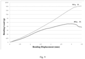
- FIG. 9 is a diagram schematically illustrating a bending load-bearing performance comparison between the elastic tubes respectively adopting the conventional transverse slot and the modified transverse slot of Fig. 7a , in which the horizontal axis represents the bending displacement (measured in mm) and in which the vertical axis represents the bending load (measured in gram).
- the transverse slot 11 may extend in a curved shape on the circumferential surface of the elastic tube 1. That is, the transverse slot 11 appears curved in a front view of the elastic tube 1, and arc-shaped in a top view of the elastic tube 1.
- the transverse slot is formed in the elastic tube 1 by a laser cutting.
- the force sensor 10 further includes strain gauge(s) arranged on the outer wall of the elastic tube 1. The number of the strain gauge(s) corresponds to the number of the transverse slot(s). Each strain gauge may be provided on either a pierced or non-pierced section of the elastic tube 1.
- each strain gauge is arranged on a non-pierced section of the elastic tube 1. More preferably, a plurality of the transverse slots 11 are axially spaced apart from one another across the elastic tube 1 and staggered from one another along the circumferential direction thereof, with each strain gauge preferably disposed between opposing ends of the respective transverse slot.
- the force sensor includes an elastic tube and a strain gauge arranged on the elastic tube.
- a transverse slot is formed in the elastic tube, and at least one first limiting structure is disposed between opposing ends of the transverse slot.
- Each first limiting structure includes a first limiting portion connected to a wall of the transverse slot and a second limiting portion connected to the other wall of the transverse slot.
- the transverse slot is maintained within a predetermined deformation range that can avoid breakage of the elastic tube and result in a prolonged service life of the strain gauge.
- adding one or more such limiting structures will not lead to increased structural complexity or impaired overall appearance of the elastic tube, and the limiting structures themselves are very easy to form and suitable for industrial production and use.
Landscapes
- Health & Medical Sciences (AREA)
- Life Sciences & Earth Sciences (AREA)
- Surgery (AREA)
- Engineering & Computer Science (AREA)
- Physics & Mathematics (AREA)
- General Health & Medical Sciences (AREA)
- Animal Behavior & Ethology (AREA)
- Veterinary Medicine (AREA)
- Public Health (AREA)
- Molecular Biology (AREA)
- Biomedical Technology (AREA)
- Heart & Thoracic Surgery (AREA)
- Medical Informatics (AREA)
- Nuclear Medicine, Radiotherapy & Molecular Imaging (AREA)
- Otolaryngology (AREA)
- Cardiology (AREA)
- Plasma & Fusion (AREA)
- General Physics & Mathematics (AREA)
- Biophysics (AREA)
- Pathology (AREA)
- Vascular Medicine (AREA)
- Physiology (AREA)
- Media Introduction/Drainage Providing Device (AREA)
Description
- The present invention relates to the technical field of medical instruments and, more specifically, to a force sensor and an electrophysiology catheter.
- In recent years, catheter systems have been developed for interventional treatment of, for example, cardiac arrhythmias and refractory hypertension. For example, in the treatment of atrial fibrillation, one type of cardiac arrhythmia, an ablation or mapping catheter may be introduced into the heart via a vein or artery to find an aberrant electrical signal position or pathway by endocardial mapping, and then apply energy at the position or pathway to ablate it to eliminate or alter undesirable electrical signals, thus achieving curative results. Another example is the treatment of refractory hypertension through renal artery ablation, in which an ablation catheter may be arterially introduced into an artery connecting the abdominal aorta and the kidney to ablate and block the parasympathetic nerve pathway to lower the blood pressure.
- For ablation therapy, how strongly an electrode disposed on a distal end of the used catheter contacts the target vessel wall or tissue is considered very important. Weak contact will lead to a superficial ablation lesion, and is thus incapable of allowing effective blockage of the aberrant electrical signals or nerve conduction. However, excessively strong contact may probably lead to perforation of the tissue, i.e., an increased safety risk. In order to avoid these issues, existing catheters of this type with force sensors at the distal end can effectively sense the contact strength between the electrode and the vessel wall or tissue. For instance, magnetic position sensors may be equipped in such a catheter to sense contact strength between the distal end thereof and the target organ. However, such sensors suffer from certain limitations in practice, such as tending to give distorted results due to interference from external magnetic fields and limiting other catheter functionalities such as three-dimensional magnetic positioning due to the use of magnetic fields. There are also catheter systems using force-sensitive materials as force sensors for sensing loads on the distal end. Although such systems are good at axial load measurement, they are lack of accuracy in non-axial load measurement. There are still other catheters employing fiber-optic systems for sensing contact forces with the vessel wall or organ, but they are difficult to package and make and expensive and require external electrical signal devices.
-
Fig. 1 schematically illustrates a conventional electrophysiology catheter, with a force sensor, passing through an intracardiac guide sheath. As shown inFig. 1 , aguide sheath 20 establishes a channel through which an electrophysiology catheter with aforce sensor 10 can be delivered into the body to perform an associated interventional procedure. The electrophysiology catheter may be an ablation catheter, a mapping catheter or another type of electrophysiology catheter. - The electrophysiology catheter includes a distal end at which the
force sensor 10 is disposed. Theforce sensor 10 is configured to obtain the magnitude and direction of a contact force that occurs when the distal end of the catheter is brought into contact with the surface of a vessel wall or tissue. In other words, theforce sensor 10 is configured to measure a reaction force in response to the contact force exerted by the catheter's distal end on the vessel wall or tissue. - In practice, in order to guide such electrophysiology catheters to various target sites,
distinct guide sheaths 20 are designed with distal ends having different curved shapes. Additionally, such aguide sheath 20 should be constructed to be relatively stiff in order to maintain the designed curved shape while ensuring that a respective electrophysiology catheter can reach the target site. Consequently, as the electrophysiology catheter is guided through theguide sheath 20, theforce sensor 10 tends to experience a great deformation under the action of significant forces exerted by theguide sheath 20. - This requires the
force sensor 10 to be able to withstand large bending loads. Otherwise, when impacted by a large force, theforce sensor 10 may break, leading to failure or a shortened service life of a strain gauge therein due to a load exceeding its measuring range. - As shown in
Fig. 2 , theconventional force sensor 10 may include anelastic tube 1 having a wall in which one or more pierced transverse slots 11 (i.e., slots formed by cutting though the wall of the elastic tube 1) are formed in order to enhance elasticity of the elastic tube 1 (especially a metal tube) and amplify any deformation thereof under the action of thetransverse slots 11. A strain gauge on theelastic tube 1 may then sense the amplified deformation and outputs an electrical signal indicating the change. Preferably, multiple suchtransverse slots 11 are formed along different circumferential circles and spaced from one another circumferentially in a staggered manner. That is, orthographic projections of thesetransverse slots 11 on a single plane are preferably distributed in a circumferentially staggered pattern. - Each
transverse slot 11 is an arc-shaped slot cut along a circumference of the wall of theelastic tube 1 and provided at its both opposing ends each with alongitudinal slot 12 for mitigating stress concentration at the opposing ends of thetransverse slot 11 and thus increasing its tensile strength. - However, as shown in
Figs. 3a and 3b , when theelastic tube 1 is stretched, thetransverse slot 11 will axially deform at its both axial sides away from the initial positions indicated by dashed lines in the figure, which will still cause the issue of "stress concentration" at the opposing ends. In particular, when the deformation exceeds a certain limit, thetransverse slot 11 may crack, or even break, at the opposing ends, leading to permanent failure of the strain gauge due to the excessive strain load exceeding its maximum measuring range. -
CN 106 264 719 A discloses an electrophysiological catheter including distal end of catheter provided with pressure transducer including elastic body and foil gauge. -
CN 107 496 055 A discloses a heart valve delivery catheter including outer tube assembly and an inner tube component arranged in the outer tube assembly. - It is an objective of the present invention is to provide a force sensor and an electrophysiology catheter. The force sensor can be effectively avoided from experiencing any significant impact when the electrophysiology catheter is guided through a sheath. In this way, it is maintained within a predetermined deformation range that prevents breakage of an elastic tube of the sensor and enables an extended service life of any strain gauge therein.
- To achieve the above objective, the present invention provides a force sensor as defined in
claim 1. - Preferably, the force sensor further comprises at least one second limiting structure disposed between the opposing ends of the transverse slot, each of the at least one second limiting structure comprising a third limiting portion connected to the first wall and a fourth limiting portion connected to the second wall, and
when the transverse slot deforms axially, the third limiting portion and fourth limiting portion are able to responsively move relative to each other until being engaged with each other. - Preferably, the third limiting portion is a male portion with a third external surface and the fourth limiting portion is a female portion with a fourth external surface, the third external surface and the forth external surface being arranged opposite to each other and defining a clearance between the third external surface and the forth external surface, and wherein the third limiting portion is confined within the fourth limiting portion.
- Preferably, the first limiting portion, second limiting portion, third limiting portion and fourth limiting portion are of a same shape.
- Preferably, the force sensor comprises a plurality of the first limiting structures, and wherein each of the at least one second limiting structure is disposed between adjacent two of the first limiting structures, the third limiting portion is a portion between adjacent two of the first limiting portions thereof and the fourth limiting portion is a gap between adjacent two of the second limiting portions.
- Preferably, an external surface of the second limiting portion and an external surface of the third limiting portion are arranged axially opposite to each other and define a clearance between the external surface of the second limiting portion and the external surface of the third limiting portion.
- Preferably, the second limiting portion comprises a second vertical portion and a second horizontal portion, and the third limiting portion comprises a third vertical portion and a third horizontal portion, the second vertical portion being connected to the second wall, the third vertical portion being connected to the first wall, the second and third horizontal portions together forming an engagement.
- Preferably, the male portions are trapezoidal, L-shaped or T-shaped.
- Preferably, the force sensor further comprises two longitudinal slots arranged at the respective opposing ends of the transverse slot.
- Preferably, the transverse slot extends in a curved shape on a circumferential surface of the elastic tube.
- Preferably, the transverse slot is formed in the elastic tube by laser cutting.
- Preferably, the force sensor comprises a plurality of the transverse slots and a plurality of the strain gauges, the transverse slots spaced apart from one another across the elastic tube in an axial direction of the elastic tube and staggered from one another along a circumferential direction of the elastic tube, each of the strain gauges disposed between two opposing ends of a respective one of the transverse slots.
- According to the present invention, the force sensor includes an elastic tube and a strain gauge arranged on the elastic tube. A pierced transverse slot is formed in the elastic tube, and at least one first limiting structure is disposed between two opposing ends of the transverse slot. Each first limiting structure includes a first limiting portion connected to a wall of the transverse slot and a second limiting portion connected to the other wall of the transverse slot. In the event of an axial deformation occurring to the transverse slot, the first and second limiting portions will simultaneously move relative to each other. In particular, when the axial deformation reaches a certain level, the two limiting portions will engage with each other. As a result, the transverse slot is maintained within a predetermined deformation range that can avoid breakage of the elastic tube and result in a prolonged service life of the strain gauge.
-
-
Fig. 1 schematically illustrates a conventional electrophysiology catheter, with a force sensor, passing through an intracardiac guide sheath. -
Fig. 2 is a structural schematic of an elastic tube in the conventional force sensor. -
Fig. 3a is a structural schematic of a transverse slot in the conventional elastic tube that is not axially deformed. -
Fig. 3b is another structural schematic of the transverse slot that is being axially deformed. -
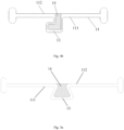
Fig. 4a is a schematic perspective view of an elastic tube with an L-shaped limiting structure according to a first embodiment of the present invention. -
Fig. 4b is a plan view schematically illustrating the L-shaped limiting structure ofFig. 4a that is arranged at each of opposing ends of a transverse slot. -
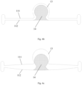
Fig. 5a is a plan view schematically illustrating a trapezoidal limiting structure at each of opposing ends of a transverse slot according to a second embodiment of the present invention. -
Fig. 5b is a schematic illustration of the transverse slot ofFig. 5a that has experienced an axial deformation. -
Fig. 6a is a schematic perspective view of a major arc-shaped limiting structure in an elastic tube according to an example not belonging to the present invention. -
Fig. 6b is a plan view schematically illustrating the major arc-shaped limiting structure of theFig. 6a that is arranged at each of opposing ends of a transverse slot. -
Fig. 6c is a schematic illustration of the transverse slot ofFig. 6b that has experienced an axial deformation. -
Fig. 6d is a plan view schematically illustrating a plurality of major arc-shaped limiting structures at opposing ends of a transverse slot according to an example not belonging to the present invention. -
Fig. 7a is a schematic perspective view of a plurality of L-shaped limiting structures in an elastic tube according to a fifth embodiment of the present invention. -
Fig. 7b is a schematic plan view partially illustrating the plurality of L-shaped limiting structures ofFig. 7a that are arranged at opposing ends of a transverse slot. -
Fig. 7c is a schematic plan view partially illustrating the limiting structures ofFig. 7a that are arranged at the opposing ends of the transverse slot when the transverse slot does not deform at all. -
Fig. 7d is a schematic plan view partially illustrating the limiting structures ofFig. 7a that are arranged at the opposing ends of the transverse slot after the transverse slot has experienced a deformation. -
Fig. 8 is a schematic perspective view of a plurality of trapezoidal limiting structures in an elastic tube according to a sixth embodiment of the present invention. -
Fig. 9 is a diagram schematically illustrating a bending load-bearing performance comparison drawn between elastic tubes respectively adopting a conventional transverse slot and the modified transverse slot ofFig. 7a . - In these figures,
- 10 denotes a force sensor; 1, an elastic tube; 11, a transverse slot; 111, a first wall; 112, a second wall; 12, a longitudinal slot; 13, a first limiting portion; 14, a second limiting portion; 15, a third limiting portion; 16, a fourth limiting portion; and
- 20, a guide sheath.
- Specific embodiments of the proposed force sensor and electrophysiology catheter will be described in greater detail with reference to the accompanying drawings so that the present invention will become more apparent and readily understood.
- Additionally, while the present invention is described in detail with reference to the annexed schematic figures, these figures are presented only for the purpose of facilitating the detailed description of the examples rather than limiting the invention in any sense.
- As used herein, the terms "proximal" and "distal" describe relative orientations, positions and directions between elements or actions, viewed by a physician operating the product. Without wishing to be limiting, a "proximal end" usually refers to an end of the product close to the physician during normal operation, while a "distal end" usually refers to an end thereof that enters the patient first. "Axial" and "longitudinal" refer to an axial direction of an elastic tube, while "circumferential" and "transverse" refer to a circumferential direction thereof.
- As used in the specification, the singular forms "a," "an" and "the" include plural referents unless the context clearly dictates otherwise. As used in the specification, the term "or" is generally employed in the sense including "and/or" unless the context clearly dictates otherwise.
- According to the present invention, in order to enhance breakage resistance of the elastic tube, each
transverse slot 11 is maintained within a predetermined deformation range that ensures that theelastic tube 1 will not break. To this end, at least one first limiting structure is added between opposing ends of eachtransverse slot 11. - In response to an axial deformation of the
transverse slot 11, a relative movement will occur in the at least one first limiting structure, and when reaching a limit position, an engagement will occur, defining a maximum deformation amount of thetransverse slot 11. In this way, any significant impact can be effectively avoided when the electrophysiology catheter is guided through a sheath, and theelastic tube 1 can be maintained within a predetermined deformation range that prevents breakage of the elastic tube and enables an extended service life of a strain gauge. Generally, such a strain gauge provides a strain measurement range of ±20,000 microstrains. Accordingly, the at least one first limiting structure is generally configured to limit the maximum deformation amount to be not over 20,000 microstrains. - According to the present invention, each first limiting structure may include a first limiting portion and a second limiting portion. The first limiting portion is connected to a first wall of the
transverse slot 11. Upon any axial deformation of the first wall, the first limiting portion will experience a synchronous axial displacement. Additionally, the second limiting portion is connected to a second wall of thetransverse slot 11. Similarly, when the second wall deforms axially, a synchronous axial displacement will responsively occur to the second limiting portion. The first wall opposes the second wall along a widthwise direction of thetransverse slot 11. - Thus, when the
elastic tube 1 is stressed and stretched by a force, both the first and second walls will deform accordingly, driving the first and second limiting portions to move relative to (i.e., toward or away from) each other. When the axial load is below a predefined threshold (e.g., 500 g), the relative movement of the first and second limiting portions will be accommodated in a preset clearance without resulting in a contact therebetween. However, when the axial load exceeds the predefined threshold, the first and second limiting portions will move toward or away from each other until the limit position is reached, where they cooperate to form a snap-fit engagement that prevents any of them from further moving. At this point, thetransverse slot 11 deforms by a maximum allowable amount under the action of the snap-fit engagement of the first and second limiting portions. - Obviously, in order to control the maximum deformation amount of the
transverse slot 11, an axial clearance between the first and second limiting portions is necessary for allowing an axial relative movement between the two limiting portions while ensuring a space for compressive or tensile deformation of theelastic tube 1. Therefore, the maximum deformation amount can be controlled, in general terms, below 20,000 microstrains by suitably setting a dimension of the clearance. - Various examples of the limiting structure according to embodiments of the present invention will be described in greater detail below with reference to
Figs. 4a to 9 , but the present invention is not limited to these listed examples. - As shown in
Figs. 4a and4b , in a first embodiment, atransverse slot 11 formed in anelastic tube 1 has afirst wall 111 and asecond wall 112, arranged along a widthwise direction of the slot. The widthwise direction is defined as an axial direction when a center axis of the transverse slot coincides with a center axis of the elastic tube. A first limitingportion 13 is arranged on thefirst wall 111, while a second limitingportion 14 is arranged on thesecond wall 112. The first and second limitingportions portion 13 is a female L-shaped portion with a first internal surface, while the second limitingportion 14 is a male L-shaped portion with a second external surface. When theelastic tube 1 is not stressed, the first internal surface and the second external surface oppose each other with a clearance therebetween. In this way, when theelastic tube 1 experiences a force, the second limitingportion 14 is able to move with thetransverse slot 11 relative to (i.e., to approach or get away from) the first limitingportion 13 while being always confined within the first limitingportion 13 without dislodging therefrom. - As shown in
Figs. 5a and5b , in a second embodiment, atransverse slot 11 formed in anelastic tube 1 also has afirst wall 111 and asecond wall 112. A first limitingportion 13 is arranged on thefirst wall 111, while a second limitingportion 14 is arranged on thesecond wall 112. In this embodiment, the first limitingportion 13 is a trapezoidal male portion, while the second limitingportion 14 is a trapezoidal female portion. Following the same principles, when theelastic tube 1 is stressed and stretched (as shown inFig. 5b ), the trapezoidal male and female portions will move away from each other until a limit position is reached where a maximum cross-sectional width of the trapezoidal male portion is greater than a minimum cross-sectional width of the trapezoidal female portion (i.e., an opening width), bringing an external surface of the trapezoidal male portion into abutment with an internal surface of the trapezoidal female portion and thus resulting in a snap fit engagement therebetween. - As shown in
Figs. 6a to 6c , in an example not belonging to the invention, atransverse slot 11 formed in anelastic tube 1 also has afirst wall 111 and asecond wall 112. A first limitingportion 13 is arranged on thefirst wall 111, while a second limitingportion 14 is arranged on thesecond wall 112. In this embodiment, the first limitingportion 13 is a major arc-shaped female portion, while the second limitingportion 14 is a major arc-shaped male portion. Following the same principles, when theelastic tube 1 is stressed and stretched (as shown inFig. 6c ), the major arc-shaped male and female portions will move away from each other until a limit position is reached where an external surface of the major arc-shaped male portion is brought into close abutment with an internal surface of the major arc-shaped female portion, resulting in a snap fit engagement therebetween, because the major arc-shaped male portion has at least one portion having a cross-sectional width that is greater than an opening width of the major arc-shaped female portion. -
Fig. 6d shows another example not belonging to the invention that is similar to the one previously introduced, except that a plurality of first limiting structures are arranged on opposing ends of atransverse slot 11 and spaced apart from one another. For the sake of brevity, similarities between the two embodiments will not be described herein. The arrangement of the plurality of first limiting structures imparts increased impact resistance and reliability to theelastic tube 1. Even when any of the first limiting structures fails, the remaining one(s) can still provide a limiting effect. In addition, theelastic tube 1 also obtains improved toughness and enhanced sensing ability. - The present invention further provides a fifth embodiment, The fifth embodiment is similar to the first embodiment except that, between adjacent two first limiting structures, a second limiting structure is arranged, which includes a third limiting
portion 15 connected to thefirst wall 111 of thetransverse slot 11 and a fourth limitingportion 16 connected to thesecond wall 112 of thetransverse slot 11. For the sake of brevity, similarities between the two embodiments will not be described herein. In response to an axial deformation of thetransverse slot 11, the third and fourth limitingportions - As shown in
Fig. 7a , the third limitingportion 15 is a male portion with a third external surface, while the fourth limitingportion 16 is a female portion with a fourth internal surface that opposes the third internal surface with a clearance therebetween. Additionally, the third limitingportion 15 is confined within the fourth limitingportion 16. In this embodiment, the first limitingportion 13, second limitingportion 14, third limitingportion 15 and fourth limitingportions 16 are in the same shape. In fact, the third limitingportion 15 is composed of a portion between the adjacent two first limitingportions 13, while the fourth limitingportion 16 is composed of a gap between the adjacent two second limitingportions 14. - More specifically, as shown in
Figs. 7c and7d , each second limitingportion 14 has a second vertical portion and a second horizontal portion, and the third limitingportion 15 has a third vertical portion and a third horizontal portion. The second vertical portion is connected to thesecond wall 112, while the third vertical portion is connected to thefirst wall 111. The second horizontal portion axially opposes the third horizontal portion, thus forming a snap mechanism. Here, mutually-facing surfaces of the second and third horizontal portions are referred to as their "internal surfaces", and the respective opposite surfaces as their "external surfaces". Initially, there is a clearance between the internal surfaces of the two horizontal portions (as shown inFig. 7c ), which allows a relative movement (generally, an approaching movement) of the two limiting portions. As an associated deformation increases, the horizontal portions of the two limiting portions will be finally engaged with each other (as shown inFig. 7d ). That is, the internal surfaces of the two horizontal portions are brought into engagement with each other, which prevents the two horizontal portions from further moving toward each other anymore. In other words, after an approaching movement is made from the positions shown inFig. 7c , the horizontal portions of the two limitingportions transverse slot 11. In other embodiments, the horizontal portions of the two limitingportions Fig. 7c until the external surface of the second horizontal portion in the second limitingportion 14 abuts against the internal surface of the first limiting portion 13 (as shown inFig. 7b ) so that their further relative movement is again disallowed. -
Fig. 8 shows a sixth embodiment that is similar to the fifth embodiment except that the first limitingportion 13, second limitingportion 14, third limitingportion 15 and fourth limitingportion 16 are all trapezoidal. For the sake of brevity, similarities between the two embodiments will not be described herein. In case of the first limitingportion 13, second limitingportion 14, third limitingportion 15 and fourth limitingportion 16 being of the same shape, the two male limiting structures will be identically strong, preventing either of them from earlier breakage due to lower strength. In addition, the identical shape allows a maximized contact area between them, preventing the occurrence of insufficient contact therebetween. Further, relatively speaking, the plurality of L-shaped limiting structures can provide a more secure engagement than those of other shapes such as the trapezoidal or major arc shape. - Experimental results demonstrate that, a conventional
transverse slot 11 without any limiting structure arranged between its opposing ends can withstand a maximum bending load of 463 g and theelastic tube 1 will break upon any increase in the load, as indicated by the curve s2 inFig. 9 . In spite of this, when advanced through aguide sheath 20, it is very likely for aforce sensor 10 to experience a load of 500 g or greater when the advancement is too fast or an inappropriate driving force is applied. By contrast, a maximum bending load that atransverse slot 11 adopting the structure ofFigs. 7a and7b can withstand is greater than 900 g, as indicated by the curve s1 inFig. 9 , undoubtedly meeting the practical requirements.Fig. 9 is a diagram schematically illustrating a bending load-bearing performance comparison between the elastic tubes respectively adopting the conventional transverse slot and the modified transverse slot ofFig. 7a , in which the horizontal axis represents the bending displacement (measured in mm) and in which the vertical axis represents the bending load (measured in gram). - In any of the above embodiments, the
transverse slot 11 may extend in a curved shape on the circumferential surface of theelastic tube 1. That is, thetransverse slot 11 appears curved in a front view of theelastic tube 1, and arc-shaped in a top view of theelastic tube 1. Preferably, the transverse slot is formed in theelastic tube 1 by a laser cutting. Theforce sensor 10 further includes strain gauge(s) arranged on the outer wall of theelastic tube 1. The number of the strain gauge(s) corresponds to the number of the transverse slot(s). Each strain gauge may be provided on either a pierced or non-pierced section of theelastic tube 1. Here, the term "pierced section" refers to a portion encompassing one of the transverse slot(s) (i.e., the strain gauge can cover the transverse slot 11), whereas the term "non-pierced section" refers to a portion of theelastic tube 1 that is not pierced. Preferably, each strain gauge is arranged on a non-pierced section of theelastic tube 1. More preferably, a plurality of thetransverse slots 11 are axially spaced apart from one another across theelastic tube 1 and staggered from one another along the circumferential direction thereof, with each strain gauge preferably disposed between opposing ends of the respective transverse slot. - At last, while a few preferred embodiments of the present invention have been described above, the present invention is not limited to the scope of these disclosed embodiments. For example, in case of a plurality of limiting structures being provided, all of them may have the same structure, or one or more of them may have a different structure.
- According to embodiments of the present invention, the force sensor includes an elastic tube and a strain gauge arranged on the elastic tube. A transverse slot is formed in the elastic tube, and at least one first limiting structure is disposed between opposing ends of the transverse slot. Each first limiting structure includes a first limiting portion connected to a wall of the transverse slot and a second limiting portion connected to the other wall of the transverse slot. In the event of an axial deformation occurring to the transverse slot, the first and second limiting portions will responsively move relative to each other. In particular, when the axial deformation reaches a certain level, the two limiting portions will engage with each other. As a result, the transverse slot is maintained within a predetermined deformation range that can avoid breakage of the elastic tube and result in a prolonged service life of the strain gauge. In particular, adding one or more such limiting structures will not lead to increased structural complexity or impaired overall appearance of the elastic tube, and the limiting structures themselves are very easy to form and suitable for industrial production and use.
Claims (12)
- A force sensor (10), comprising an elastic tube (1) and a strain gauge arranged on the elastic tube (1), wherein:the force sensor (10) further comprises a pierced transverse slot (11) formed in the elastic tube (1), the transverse slot (11) having a first wall (111) and a second wall (112);the force sensor (10) characterised in that it further comprises at least one first limiting structure disposed between two opposing ends of the transverse slot (11), each of the at least first limiting structure comprising a first limiting portion (13) and a second limiting portion (14), the first limiting portion (13) being connected to the first wall (111), the second limiting portion (14) being connected to the second wall (112); the first limiting portion (13) is a female portion with a first internal surface and the second limiting portion (14) is a male portion with a second external surface, the first internal surface and the second external surface being arranged opposite to each other and defining a clearance between the first internal surface and the second external surface, and wherein the second limiting portion (14) is confined within the first limiting portion (13); andwhen the elastic tube is stretched by a force and the transverse slot (11) deforms in an axial direction of the elastic tube (1), the first limiting portion (13) and the second limiting portion (14) are able to responsively move away from each other in the axial direction until being engaged with each other;wherein the first limiting portion (13) and second limiting portion (14) are both L-shaped portions that match each other in shape; or the first limiting portion (13) is a trapezoidal male portion, and the second limiting portion (14) is a trapezoidal female portion.
- The force sensor (10) of claim 1, wherein the force sensor (10) comprises a plurality of the first limiting structures spaced apart from one another across a same circumferential surface.
- The force sensor (10) of claim 1, further comprising at least one second limiting structure disposed between the opposing ends of the transverse slot (11), each of the at least one second limiting structure comprising a third limiting portion (15) connected to the first wall (111) and a fourth limiting portion (16) connected to the second wall (112), and
when the transverse slot (11) deforms axially, the third limiting portion (15) and fourth limiting portion (16) are able to responsively move relative to each other until being engaged with each other. - The force sensor (10) of claim 3, wherein the third limiting portion (15) is a male portion with a third external surface and the fourth limiting portion (16) is a female portion with a fourth external surface, the third external surface and the forth external surface being arranged opposite to each other and defining a clearance between the third external surface and the forth external surface, and wherein the third limiting portion (15) is confined within the fourth limiting portion (16).
- The force sensor (10) of claim 3, wherein the first limiting portion (13), second limiting portion (14), third limiting portion (15) and fourth limiting portion (16) are of a same shape.
- The force sensor (10) of claim 5, wherein the force sensor (10) comprises a plurality of the first limiting structures, and wherein each of the at least one second limiting structure is disposed between adjacent two of the first limiting structures, the third limiting portion (15) is a portion between adjacent two of the first limiting portions (13) thereof and the fourth limiting portion (16) is a gap between adjacent two of the second limiting portions (14).
- The force sensor (10) of claim 5, wherein an external surface of the second limiting portion (14) and an external surface of the third limiting portion (15) are arranged axially opposite to each other and define a clearance between the external surface of the second limiting portion (14) and the external surface of the third limiting portion (15).
- The force sensor (10) of claim 7, wherein the second limiting portion (14) comprises a second vertical portion and a second horizontal portion, and the third limiting portion (15) comprises a third vertical portion and a third horizontal portion, the second vertical portion being connected to the second wall (112), the third vertical portion being connected to the first wall (111), the second and third horizontal portions together forming an engagement.
- The force sensor (10) of claim 1, wherein the force sensor (10) further comprises two longitudinal slots (12) arranged at the respective opposing ends of the transverse slot (11).
- The force sensor (10) of claim 1, wherein the transverse slot (11) extends in a curved shape on a circumferential surface of the elastic tube (1); or.
the transverse slot (11) is formed in the elastic tube (1) by laser cutting. - The force sensor (10) of claim 1, wherein the force sensor (10) comprises a plurality of the transverse slots (11) and a plurality of the strain gauges, the transverse slots (11) spaced apart from one another across the elastic tube (1) in the axial direction of the elastic tube (1) and staggered from one another along a circumferential direction of the elastic tube (1), each of the strain gauges disposed between two opposing ends of a corresponding one of the transverse slots (11).
- An electrophysiology catheter, comprising a distal end and a force sensor (10) as defined in any one of claims 1 to 11, the force sensor (10) being disposed at the distal end.
Applications Claiming Priority (2)
| Application Number | Priority Date | Filing Date | Title |
|---|---|---|---|
| CN201810142142.XA CN110160676B (en) | 2018-02-11 | 2018-02-11 | Pressure sensor and electrophysiology catheter thereof |
| PCT/CN2019/074760 WO2019154409A1 (en) | 2018-02-11 | 2019-02-11 | Pressure sensor, and electrophysiology catheter |
Publications (3)
| Publication Number | Publication Date |
|---|---|
| EP3751247A1 EP3751247A1 (en) | 2020-12-16 |
| EP3751247A4 EP3751247A4 (en) | 2021-04-07 |
| EP3751247B1 true EP3751247B1 (en) | 2024-12-18 |
Family
ID=67548747
Family Applications (1)
| Application Number | Title | Priority Date | Filing Date |
|---|---|---|---|
| EP19751623.0A Active EP3751247B1 (en) | 2018-02-11 | 2019-02-11 | Force sensor, and electrophysiology catheter |
Country Status (7)
| Country | Link |
|---|---|
| US (1) | US20200360082A1 (en) |
| EP (1) | EP3751247B1 (en) |
| CN (1) | CN110160676B (en) |
| AU (1) | AU2019218510B2 (en) |
| ES (1) | ES3001016T3 (en) |
| RU (1) | RU2752593C1 (en) |
| WO (1) | WO2019154409A1 (en) |
Families Citing this family (3)
| Publication number | Priority date | Publication date | Assignee | Title |
|---|---|---|---|---|
| GB2572809B (en) * | 2018-04-12 | 2020-11-11 | Subsea 7 Ltd | Internal inspection of pipelines |
| CN217066330U (en) * | 2021-12-30 | 2022-07-29 | 微创优通医疗科技(上海)有限公司 | Elastic tube, probe insertion structure and flexible probe |
| CN118418193B (en) * | 2024-07-02 | 2024-09-20 | 德瑞精工(深圳)有限公司 | Overload pressure-preventing closed-loop ZR shaft module and preparation method thereof |
Family Cites Families (21)
| Publication number | Priority date | Publication date | Assignee | Title |
|---|---|---|---|---|
| FR2439291A1 (en) * | 1978-10-19 | 1980-05-16 | Inst Francais Du Petrole | NEW STRESS MEASUREMENT DEVICE APPLICABLE TO A DRILLING LINING IN SERVICE |
| DE19535179A1 (en) * | 1995-09-22 | 1997-03-27 | Wolf Gmbh Richard | Angled pipe and process for its manufacture |
| EP2299917A1 (en) * | 2008-06-10 | 2011-03-30 | Sonoma Orthopedic Products, Inc. | Fracture fixation device, tools and methods |
| US8118775B2 (en) * | 2008-09-09 | 2012-02-21 | Biosense Webster, Inc. | Deflectable catheter with bonded center strut and method of manufacture for same |
| US8454504B2 (en) * | 2010-02-24 | 2013-06-04 | Meni-Med Ltd | Surgical retractor |
| CN102375586B (en) * | 2010-08-19 | 2014-12-03 | 苏州敏芯微电子技术有限公司 | Control system for identifying direction and force |
| CN202678568U (en) * | 2012-06-21 | 2013-01-16 | 长谷川精密科技股份有限公司 | shrapnel structure |
| US20140041673A1 (en) * | 2012-08-13 | 2014-02-13 | Christopher C. Walters | Devices for containing fluid and debris on endotracheal tubes, laryngeal masks, endoscopes, bronchoscopes and catheters and method of use thereof |
| CN202982206U (en) * | 2012-10-15 | 2013-06-12 | 陈平根 | Multi-electrode radio frequency ablation catheter |
| CN102860867B (en) * | 2012-10-15 | 2014-11-05 | 陈平根 | Multi-electrode radio frequency ablation catheter and design method thereof |
| WO2014174662A1 (en) * | 2013-04-26 | 2014-10-30 | テルモ株式会社 | Ablation catheter |
| EP3009104B1 (en) * | 2014-10-14 | 2019-11-20 | St. Jude Medical, Cardiology Division, Inc. | Flexible catheter and methods of forming same |
| US11007345B2 (en) * | 2016-10-05 | 2021-05-18 | Orbusneich Medical Pte. Ltd. | Modular vascular catheter |
| CN104398330B (en) * | 2014-12-19 | 2017-07-07 | 湖南埃普特医疗器械有限公司 | Stent delivery system |
| CN106264719B (en) * | 2016-07-29 | 2019-07-23 | 上海微创电生理医疗科技股份有限公司 | Electrophysiological catheter |
| CN106768535B (en) * | 2017-01-12 | 2023-06-16 | 福建省莆田市衡力传感器有限公司 | Double-range detection torque sensor with overload protection and manufacturing method thereof |
| CN107091261B (en) * | 2017-02-14 | 2020-10-09 | 珠海普生医疗科技有限公司 | Snake bone processing method |
| CN108720919B (en) * | 2017-04-24 | 2019-07-09 | 四川锦江电子科技有限公司 | A kind of ablation catheter with flexible distal |
| CN106974724B (en) * | 2017-04-24 | 2019-12-03 | 四川锦江电子科技有限公司 | A kind of ablation catheter with pressure detecting function |
| CN107477124A (en) * | 2017-08-08 | 2017-12-15 | 扬州中碟弹簧制造有限公司 | A kind of spring of stretch-proof and compression |
| CN107496055B (en) * | 2017-08-10 | 2021-06-08 | 上海微创心通医疗科技有限公司 | Heart valve delivery catheter and delivery system |
-
2018
- 2018-02-11 CN CN201810142142.XA patent/CN110160676B/en active Active
-
2019
- 2019-02-11 ES ES19751623T patent/ES3001016T3/en active Active
- 2019-02-11 US US16/967,327 patent/US20200360082A1/en not_active Abandoned
- 2019-02-11 WO PCT/CN2019/074760 patent/WO2019154409A1/en not_active Ceased
- 2019-02-11 EP EP19751623.0A patent/EP3751247B1/en active Active
- 2019-02-11 AU AU2019218510A patent/AU2019218510B2/en active Active
- 2019-02-11 RU RU2020129581A patent/RU2752593C1/en active
Also Published As
| Publication number | Publication date |
|---|---|
| AU2019218510B2 (en) | 2021-03-11 |
| CN110160676B (en) | 2021-10-26 |
| ES3001016T3 (en) | 2025-03-04 |
| WO2019154409A1 (en) | 2019-08-15 |
| US20200360082A1 (en) | 2020-11-19 |
| EP3751247A4 (en) | 2021-04-07 |
| EP3751247A1 (en) | 2020-12-16 |
| AU2019218510A1 (en) | 2020-09-17 |
| CN110160676A (en) | 2019-08-23 |
| RU2752593C1 (en) | 2021-07-29 |
Similar Documents
| Publication | Publication Date | Title |
|---|---|---|
| US20220387101A1 (en) | Catheter with atraumatic tip | |
| EP3492033B1 (en) | Force sensor for an electrophysiology catheter | |
| EP2327365B1 (en) | Catheter with pressure measuring tip | |
| EP2420196B1 (en) | Catheter with thin film pressure sensing distal tip | |
| AU2019218510B2 (en) | Pressure sensor, and electrophysiology catheter | |
| EP2749214B1 (en) | Double loop lasso with single puller wire for bi-directional actuation | |
| EP3095482A1 (en) | Catheter with adjustable deflection | |
| EP3624717B1 (en) | Optical force sensing catheter system | |
| EP3629894B1 (en) | Catheter and spring element for contact force sensing | |
| KR20230029758A (en) | Deflectable elongated guidewire assembly | |
| US20200323585A1 (en) | Ablation catheter tip with flexible electronic circuitry | |
| US12005216B2 (en) | Esophageal deviator | |
| EP4410185B1 (en) | Arrhythmia diagnosis electrode apparatus having reduced directional stiffness | |
| CN118266892A (en) | Arrhythmia diagnostic electrode device with reduced directional stiffness | |
| AU2015202746A1 (en) | Catheter with pressure measuring tip |
Legal Events
| Date | Code | Title | Description |
|---|---|---|---|
| STAA | Information on the status of an ep patent application or granted ep patent |
Free format text: STATUS: THE INTERNATIONAL PUBLICATION HAS BEEN MADE |
|
| PUAI | Public reference made under article 153(3) epc to a published international application that has entered the european phase |
Free format text: ORIGINAL CODE: 0009012 |
|
| STAA | Information on the status of an ep patent application or granted ep patent |
Free format text: STATUS: REQUEST FOR EXAMINATION WAS MADE |
|
| 17P | Request for examination filed |
Effective date: 20200811 |
|
| AK | Designated contracting states |
Kind code of ref document: A1 Designated state(s): AL AT BE BG CH CY CZ DE DK EE ES FI FR GB GR HR HU IE IS IT LI LT LU LV MC MK MT NL NO PL PT RO RS SE SI SK SM TR |
|
| AX | Request for extension of the european patent |
Extension state: BA ME |
|
| A4 | Supplementary search report drawn up and despatched |
Effective date: 20210305 |
|
| RIC1 | Information provided on ipc code assigned before grant |
Ipc: A61B 18/12 20060101ALI20210301BHEP Ipc: A61M 25/00 20060101ALI20210301BHEP Ipc: G01L 1/04 20060101AFI20210301BHEP Ipc: A61B 18/00 20060101ALI20210301BHEP Ipc: G01L 1/22 20060101ALI20210301BHEP |
|
| DAV | Request for validation of the european patent (deleted) | ||
| DAX | Request for extension of the european patent (deleted) | ||
| STAA | Information on the status of an ep patent application or granted ep patent |
Free format text: STATUS: EXAMINATION IS IN PROGRESS |
|
| 17Q | First examination report despatched |
Effective date: 20230626 |
|
| GRAP | Despatch of communication of intention to grant a patent |
Free format text: ORIGINAL CODE: EPIDOSNIGR1 |
|
| STAA | Information on the status of an ep patent application or granted ep patent |
Free format text: STATUS: GRANT OF PATENT IS INTENDED |
|
| RIC1 | Information provided on ipc code assigned before grant |
Ipc: A61B 90/00 20160101ALI20240814BHEP Ipc: A61B 9/00 20060101ALI20240814BHEP Ipc: A61B 18/14 20060101ALI20240814BHEP Ipc: A61B 5/00 20060101ALI20240814BHEP Ipc: A61B 5/0215 20060101ALI20240814BHEP Ipc: G01L 1/22 20060101ALI20240814BHEP Ipc: A61M 25/00 20060101ALI20240814BHEP Ipc: A61B 18/00 20060101ALI20240814BHEP Ipc: A61B 18/12 20060101ALI20240814BHEP Ipc: G01L 1/04 20060101AFI20240814BHEP |
|
| INTG | Intention to grant announced |
Effective date: 20240826 |
|
| GRAS | Grant fee paid |
Free format text: ORIGINAL CODE: EPIDOSNIGR3 |
|
| GRAA | (expected) grant |
Free format text: ORIGINAL CODE: 0009210 |
|
| STAA | Information on the status of an ep patent application or granted ep patent |
Free format text: STATUS: THE PATENT HAS BEEN GRANTED |
|
| AK | Designated contracting states |
Kind code of ref document: B1 Designated state(s): AL AT BE BG CH CY CZ DE DK EE ES FI FR GB GR HR HU IE IS IT LI LT LU LV MC MK MT NL NO PL PT RO RS SE SI SK SM TR |
|
| REG | Reference to a national code |
Ref country code: CH Ref legal event code: EP |
|
| REG | Reference to a national code |
Ref country code: DE Ref legal event code: R096 Ref document number: 602019063670 Country of ref document: DE |
|
| REG | Reference to a national code |
Ref country code: IE Ref legal event code: FG4D Ref country code: NL Ref legal event code: FP |
|
| REG | Reference to a national code |
Ref country code: ES Ref legal event code: FG2A Ref document number: 3001016 Country of ref document: ES Kind code of ref document: T3 Effective date: 20250304 |
|
| REG | Reference to a national code |
Ref country code: LT Ref legal event code: MG9D |
|
| PG25 | Lapsed in a contracting state [announced via postgrant information from national office to epo] |
Ref country code: HR Free format text: LAPSE BECAUSE OF FAILURE TO SUBMIT A TRANSLATION OF THE DESCRIPTION OR TO PAY THE FEE WITHIN THE PRESCRIBED TIME-LIMIT Effective date: 20241218 |
|
| PG25 | Lapsed in a contracting state [announced via postgrant information from national office to epo] |
Ref country code: FI Free format text: LAPSE BECAUSE OF FAILURE TO SUBMIT A TRANSLATION OF THE DESCRIPTION OR TO PAY THE FEE WITHIN THE PRESCRIBED TIME-LIMIT Effective date: 20241218 |
|
| PG25 | Lapsed in a contracting state [announced via postgrant information from national office to epo] |
Ref country code: BG Free format text: LAPSE BECAUSE OF FAILURE TO SUBMIT A TRANSLATION OF THE DESCRIPTION OR TO PAY THE FEE WITHIN THE PRESCRIBED TIME-LIMIT Effective date: 20241218 |
|
| PG25 | Lapsed in a contracting state [announced via postgrant information from national office to epo] |
Ref country code: NO Free format text: LAPSE BECAUSE OF FAILURE TO SUBMIT A TRANSLATION OF THE DESCRIPTION OR TO PAY THE FEE WITHIN THE PRESCRIBED TIME-LIMIT Effective date: 20250318 |
|
| PG25 | Lapsed in a contracting state [announced via postgrant information from national office to epo] |
Ref country code: LV Free format text: LAPSE BECAUSE OF FAILURE TO SUBMIT A TRANSLATION OF THE DESCRIPTION OR TO PAY THE FEE WITHIN THE PRESCRIBED TIME-LIMIT Effective date: 20241218 Ref country code: GR Free format text: LAPSE BECAUSE OF FAILURE TO SUBMIT A TRANSLATION OF THE DESCRIPTION OR TO PAY THE FEE WITHIN THE PRESCRIBED TIME-LIMIT Effective date: 20250319 |
|
| PG25 | Lapsed in a contracting state [announced via postgrant information from national office to epo] |
Ref country code: RS Free format text: LAPSE BECAUSE OF FAILURE TO SUBMIT A TRANSLATION OF THE DESCRIPTION OR TO PAY THE FEE WITHIN THE PRESCRIBED TIME-LIMIT Effective date: 20250318 |
|
| REG | Reference to a national code |
Ref country code: AT Ref legal event code: MK05 Ref document number: 1752562 Country of ref document: AT Kind code of ref document: T Effective date: 20241218 |
|
| PG25 | Lapsed in a contracting state [announced via postgrant information from national office to epo] |
Ref country code: SM Free format text: LAPSE BECAUSE OF FAILURE TO SUBMIT A TRANSLATION OF THE DESCRIPTION OR TO PAY THE FEE WITHIN THE PRESCRIBED TIME-LIMIT Effective date: 20241218 |
|
| PG25 | Lapsed in a contracting state [announced via postgrant information from national office to epo] |
Ref country code: PL Free format text: LAPSE BECAUSE OF FAILURE TO SUBMIT A TRANSLATION OF THE DESCRIPTION OR TO PAY THE FEE WITHIN THE PRESCRIBED TIME-LIMIT Effective date: 20241218 |
|
| PGFP | Annual fee paid to national office [announced via postgrant information from national office to epo] |
Ref country code: ES Payment date: 20250331 Year of fee payment: 7 |
|
| PG25 | Lapsed in a contracting state [announced via postgrant information from national office to epo] |
Ref country code: IS Free format text: LAPSE BECAUSE OF FAILURE TO SUBMIT A TRANSLATION OF THE DESCRIPTION OR TO PAY THE FEE WITHIN THE PRESCRIBED TIME-LIMIT Effective date: 20250418 |
|
| PG25 | Lapsed in a contracting state [announced via postgrant information from national office to epo] |
Ref country code: PT Free format text: LAPSE BECAUSE OF FAILURE TO SUBMIT A TRANSLATION OF THE DESCRIPTION OR TO PAY THE FEE WITHIN THE PRESCRIBED TIME-LIMIT Effective date: 20250421 |
|
| PG25 | Lapsed in a contracting state [announced via postgrant information from national office to epo] |
Ref country code: EE Free format text: LAPSE BECAUSE OF FAILURE TO SUBMIT A TRANSLATION OF THE DESCRIPTION OR TO PAY THE FEE WITHIN THE PRESCRIBED TIME-LIMIT Effective date: 20241218 |
|
| PG25 | Lapsed in a contracting state [announced via postgrant information from national office to epo] |
Ref country code: AT Free format text: LAPSE BECAUSE OF FAILURE TO SUBMIT A TRANSLATION OF THE DESCRIPTION OR TO PAY THE FEE WITHIN THE PRESCRIBED TIME-LIMIT Effective date: 20241218 Ref country code: RO Free format text: LAPSE BECAUSE OF FAILURE TO SUBMIT A TRANSLATION OF THE DESCRIPTION OR TO PAY THE FEE WITHIN THE PRESCRIBED TIME-LIMIT Effective date: 20241218 |
|
| PG25 | Lapsed in a contracting state [announced via postgrant information from national office to epo] |
Ref country code: SK Free format text: LAPSE BECAUSE OF FAILURE TO SUBMIT A TRANSLATION OF THE DESCRIPTION OR TO PAY THE FEE WITHIN THE PRESCRIBED TIME-LIMIT Effective date: 20241218 |
|
| PG25 | Lapsed in a contracting state [announced via postgrant information from national office to epo] |
Ref country code: CZ Free format text: LAPSE BECAUSE OF FAILURE TO SUBMIT A TRANSLATION OF THE DESCRIPTION OR TO PAY THE FEE WITHIN THE PRESCRIBED TIME-LIMIT Effective date: 20241218 |
|
| PG25 | Lapsed in a contracting state [announced via postgrant information from national office to epo] |
Ref country code: SE Free format text: LAPSE BECAUSE OF FAILURE TO SUBMIT A TRANSLATION OF THE DESCRIPTION OR TO PAY THE FEE WITHIN THE PRESCRIBED TIME-LIMIT Effective date: 20241218 |
|
| PG25 | Lapsed in a contracting state [announced via postgrant information from national office to epo] |
Ref country code: MC Free format text: LAPSE BECAUSE OF FAILURE TO SUBMIT A TRANSLATION OF THE DESCRIPTION OR TO PAY THE FEE WITHIN THE PRESCRIBED TIME-LIMIT Effective date: 20241218 |
|
| REG | Reference to a national code |
Ref country code: DE Ref legal event code: R097 Ref document number: 602019063670 Country of ref document: DE |
|
| REG | Reference to a national code |
Ref country code: CH Ref legal event code: PL |
|
| PG25 | Lapsed in a contracting state [announced via postgrant information from national office to epo] |
Ref country code: DK Free format text: LAPSE BECAUSE OF FAILURE TO SUBMIT A TRANSLATION OF THE DESCRIPTION OR TO PAY THE FEE WITHIN THE PRESCRIBED TIME-LIMIT Effective date: 20241218 |
|
| PG25 | Lapsed in a contracting state [announced via postgrant information from national office to epo] |
Ref country code: LU Free format text: LAPSE BECAUSE OF NON-PAYMENT OF DUE FEES Effective date: 20250211 |
|
| PG25 | Lapsed in a contracting state [announced via postgrant information from national office to epo] |
Ref country code: CH Free format text: LAPSE BECAUSE OF NON-PAYMENT OF DUE FEES Effective date: 20250228 |
|
| PLBE | No opposition filed within time limit |
Free format text: ORIGINAL CODE: 0009261 |
|
| STAA | Information on the status of an ep patent application or granted ep patent |
Free format text: STATUS: NO OPPOSITION FILED WITHIN TIME LIMIT |
|
| 26N | No opposition filed |
Effective date: 20250919 |
|
| PG25 | Lapsed in a contracting state [announced via postgrant information from national office to epo] |
Ref country code: IE Free format text: LAPSE BECAUSE OF NON-PAYMENT OF DUE FEES Effective date: 20250211 |
|
| PGFP | Annual fee paid to national office [announced via postgrant information from national office to epo] |
Ref country code: NL Payment date: 20260218 Year of fee payment: 8 |
|
| PGFP | Annual fee paid to national office [announced via postgrant information from national office to epo] |
Ref country code: GB Payment date: 20260220 Year of fee payment: 8 |
|
| PGFP | Annual fee paid to national office [announced via postgrant information from national office to epo] |
Ref country code: DE Payment date: 20260218 Year of fee payment: 8 |
|
| PGFP | Annual fee paid to national office [announced via postgrant information from national office to epo] |
Ref country code: BE Payment date: 20260218 Year of fee payment: 8 Ref country code: IT Payment date: 20260224 Year of fee payment: 8 |
|
| PGFP | Annual fee paid to national office [announced via postgrant information from national office to epo] |
Ref country code: FR Payment date: 20260218 Year of fee payment: 8 |